EP3560741A1 - Vorrichtung zur abdichtung eines in die karosserie eines fahrzeugs eingelassenen öffnungsfelds, und entsprechendes fahrzeug - Google Patents
Vorrichtung zur abdichtung eines in die karosserie eines fahrzeugs eingelassenen öffnungsfelds, und entsprechendes fahrzeug Download PDFInfo
- Publication number
- EP3560741A1 EP3560741A1 EP18169047.0A EP18169047A EP3560741A1 EP 3560741 A1 EP3560741 A1 EP 3560741A1 EP 18169047 A EP18169047 A EP 18169047A EP 3560741 A1 EP3560741 A1 EP 3560741A1
- Authority
- EP
- European Patent Office
- Prior art keywords
- movable panel
- plane
- sliding
- shutter
- shuttle
- Prior art date
- Legal status (The legal status is an assumption and is not a legal conclusion. Google has not performed a legal analysis and makes no representation as to the accuracy of the status listed.)
- Granted
Links
Images



Classifications
-
- B—PERFORMING OPERATIONS; TRANSPORTING
- B60—VEHICLES IN GENERAL
- B60J—WINDOWS, WINDSCREENS, NON-FIXED ROOFS, DOORS, OR SIMILAR DEVICES FOR VEHICLES; REMOVABLE EXTERNAL PROTECTIVE COVERINGS SPECIALLY ADAPTED FOR VEHICLES
- B60J1/00—Windows; Windscreens; Accessories therefor
- B60J1/08—Windows; Windscreens; Accessories therefor arranged at vehicle sides
- B60J1/12—Windows; Windscreens; Accessories therefor arranged at vehicle sides adjustable
- B60J1/16—Windows; Windscreens; Accessories therefor arranged at vehicle sides adjustable slidable
-
- B—PERFORMING OPERATIONS; TRANSPORTING
- B60—VEHICLES IN GENERAL
- B60J—WINDOWS, WINDSCREENS, NON-FIXED ROOFS, DOORS, OR SIMILAR DEVICES FOR VEHICLES; REMOVABLE EXTERNAL PROTECTIVE COVERINGS SPECIALLY ADAPTED FOR VEHICLES
- B60J7/00—Non-fixed roofs; Roofs with movable panels, e.g. rotary sunroofs
- B60J7/02—Non-fixed roofs; Roofs with movable panels, e.g. rotary sunroofs of sliding type, e.g. comprising guide shoes
- B60J7/024—Non-fixed roofs; Roofs with movable panels, e.g. rotary sunroofs of sliding type, e.g. comprising guide shoes characterised by the height regulating mechanism of the sliding panel
-
- B—PERFORMING OPERATIONS; TRANSPORTING
- B60—VEHICLES IN GENERAL
- B60J—WINDOWS, WINDSCREENS, NON-FIXED ROOFS, DOORS, OR SIMILAR DEVICES FOR VEHICLES; REMOVABLE EXTERNAL PROTECTIVE COVERINGS SPECIALLY ADAPTED FOR VEHICLES
- B60J7/00—Non-fixed roofs; Roofs with movable panels, e.g. rotary sunroofs
- B60J7/02—Non-fixed roofs; Roofs with movable panels, e.g. rotary sunroofs of sliding type, e.g. comprising guide shoes
- B60J7/04—Non-fixed roofs; Roofs with movable panels, e.g. rotary sunroofs of sliding type, e.g. comprising guide shoes with rigid plate-like element or elements, e.g. open roofs with harmonica-type folding rigid panels
- B60J7/047—Non-fixed roofs; Roofs with movable panels, e.g. rotary sunroofs of sliding type, e.g. comprising guide shoes with rigid plate-like element or elements, e.g. open roofs with harmonica-type folding rigid panels movable to overlapping or nested relationship
Definitions
- the field of the invention is that of the equipment of the bays, used in particular in motor vehicles.
- the invention relates to devices for closing an array formed in a structural element, for example in the bodywork of a vehicle, or in a door of the vehicle, and comprising a sliding mobile part capable of releasing or to close an opening by offering a flush appearance, seen from the outside.
- the invention can also equip other types of structures, such as caravans, campers, buses and coaches, minibuses, trucks, vans, boats, ...
- these devices are designed to have, seen from the outside, a flush or near-flush appearance between the body, or more generally the wall or structure, and the fixed panel of the device.
- the shutter device (hereinafter referred to as "flush bay") presented in these documents comprises a fixed part and a moving part with respect to this fixed part, or sliding panel.
- the movable part is connected to the fixed assembly by functional elements which provide the required mobility and which are reported on the face of the fixed part facing the interior of the vehicle.
- This fixed part can be made in one or more elements (placed next to each other in the same plane), for example glass or polycarbonate.
- flush bay can thus be mounted integrally independently of the vehicle, and reported from the outside, in the housing defined for this purpose by the bay, or housing, defined in the body, or more generally in the wall.
- edges of the fixed part are secured, for example by means of a bead of glue, to the edges of the bay, without any other intermediate connecting element.
- the flush bay presents, from the outside, a smooth, flush appearance, because no frame is needed on the contour of the opening formed in the fixed assembly.
- a guiding device comprising a first and a second guide rails fixedly mounted on the fixed part (or fixed structure) of the bay, on both sides. other of the opening closed by the movable panel.
- the movable panel inscribes itself in the plane of the fixed part, passing from an intermediate position of clearance, in the plane of sliding, to view of the opening and cleared from it in the closed position.
- plan here must be understood in a broader sense: the plane formed by the bay is sometimes curved, according to one or even two directions (this also justifies, in some cases, the term “substantially” used in the description and claims).
- Flush racks are an important success in many applications, including the simplicity of their manufacture and assembly, and the aesthetic appearance they can achieve.
- the seal between the movable panel and the fixed part is provided, conventionally, by a seal.
- the movable panel moves in a normal motion to its plane of form (in Y for a side window), the four corners of the movable panel moving at the same time.
- the seal is peeled off simultaneously over the entire edge of the movable panel (the seal is peeled off at one time)
- the invention therefore particularly aims to overcome the disadvantages of the prior art mentioned above.
- the object of the invention is, in at least one embodiment, to provide a shutter device for a bay that allows locking and unlocking, and more generally an opening and closing, easy, intuitive and without significant effort.
- Another object of the invention is to provide a closure device which avoids inducing adverse and undesirable effects between the movable panel and the associated sealing means.
- the invention also aims, according to at least one embodiment, to provide a new technique for guiding a movable panel of a shutter bay of a structure, such as a motor vehicle or the like, allowing the passage from a closed position, flush with the fixed panel to a sliding position, which is simple, effective and reliable.
- a closure device of a bay formed in a structure comprising a fixed part, in which is defined an opening, and at at least one sliding movable panel guided along two guide rails mounted on one face of said fixed panel, between at least one closed position of said opening, in a first plane defined by said fixed panel, said shutter plane, and a sliding position, in a second plane, said sliding plane, substantially parallel to said shutter plane, each of said guide rails carrying at least one shuttle guided in translation in said rail, each shuttle comprising two guide grooves or two fixed pins adapted to cooperate respectively with two fixed pins or two guide grooves carried by said movable panel , said closure device further comprising actuating means acting on said shuttles to ensure a translational movement of the latter in said guide rails, and the passage of the movable panel from said closed position to said sliding position, and reciprocally.
- the two guide grooves of the pions of the movable panel or the shuttle are of distinct shapes so as to ensure, when the shuttles are moved in said rails from the position of shutting, the transverse displacement relative to said rails of a first portion of the movable panel, then the transverse displacement relative to said rails of the other part of the movable panel, allowing the passage of the movable panel in an intermediate position of disengagement, in the sliding plane, facing the opening and cleared thereof.
- the path of the guide pins of the movable panel in the two guide grooves of each of the shuttles is different.
- a first guide groove of a shuttle or of the movable panel has a first portion inclined with respect to the sliding plane, allowing from the closed position the transverse displacement relative to said rails of a first portion of the movable panel and a second portion extending substantially parallel to said sliding plane, the second guide groove of said shuttle or the movable panel having a first portion extending substantially in parallel said sliding plane and a second portion inclined with respect to the sliding plane, allowing the transverse displacement relative to said rails of the other part of the movable panel, allowing the passage of the movable panel in the sliding position.
- the two guide grooves formed in each of the shuttles of the upper and lower rails are configured so as to move the front part and the rear part of the movable panel from the closed position to the sliding position, in order to act progressively. on the seal, especially in case of frost.
- the first and second guide grooves of a shuttle or the movable panel are symmetrical with respect to a central point equidistant from the two grooves.
- the inclination of the second inclined portion of the second groove relative to the sliding plane is greater than the inclination of the first inclined portion of the first groove relative to the sliding plane.
- the inclination difference is, for example, between 1 and 5 °.
- This offset makes it possible to block the movable panel in the open position so as to limit the vibrations.
- the shutter device comprises synchronization means, connecting the two shuttles equipping respectively the two rails, so that the two shuttles are operated simultaneously.
- said synchronization means comprise at least one cable or foil.
- the fixed part is provided with sealing means intended to be placed in contact with a periphery of said movable panel in said closed position.
- the movable panel is provided with sealing means intended to be placed in contact with a periphery of the opening of the fixed part in said closed position.
- the shutter device is mounted on a door or a lateral portion of the bodywork.
- the invention also relates to motor vehicles comprising at least one closure device as described above.
- This device may in particular be mounted on a side wall of the vehicle or a door, or form all or part of a roof.
- vehicle automobile means here in a broad sense, and includes including trucks, vans, buses, motor homes, ...
- Such a closure device can also be adapted to other structures with similar constraints, such as caravans, mobile homes, boats, etc.
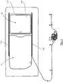
- the figure 1 illustrates a sliding panel flush bay seen from inside the vehicle.
- Such a flush bay is in the form of a set, or shutter device, ready to be placed in a bay (that is to say, an opening, or a hole) formed in the bodywork (side wall by example) or a door, or more generally in the structure of a vehicle (or a caravan or a camper, for example), or more generally a wall to receive a closure device provided with 'an opening.
- Such a closure device comprises a fixed part 11, that is to say remaining immobile relative to the structure that receives it, and a movable panel sliding, or sliding panel, 12, movable relative to the fixed part 11.
- the fixed part 11, also called fixed panel, may in particular be made of glass or polycarbonate, in one or more elements.
- the fixed part 11 is pierced with an opening closed by the movable panel 12 in the position of the figure 1 and extending in the same plane as the fixed part 11.
- This movable panel 12 comprises a glazed portion 122, a frame 121 and a locking / unlocking device.
- Rails respectively an upper rail 114 and a lower rail 115, are attached by gluing on the face of the fixed part 11 facing the inside of the vehicle.
- the rails 114 and 115 which are substantially parallel in this example, hold and slide guide the movable panel 12, which has a frame 121 connected to the rails.
- the movable panel 12 can be moved along the rails 114, 115, in a plane of sliding substantially parallel to the plane defined by the fixed part 11.
- the movable panel 12 can completely close the opening of the fixed part 11 ( figure 1 ) or partially or totally release this opening.
- the movable panel 12 can take one or more open positions, depending on its position relative to the rails 114, 115.
- the movable panel 12 can move perpendicular to the plane defined by the fixed part 11, so as to close the opening, in a closed position ( figure 1 ), in which it is flush with this fixed portion 11, so as to provide a flush assembly (body, fixed part and part mobile).
- the seal may be mounted on the frame 121 of the movable panel 12, in order to come into contact with the fixed part 11.
- the upper rail 114 carries a shuttle (not visible in the figures) and the lower rail 115 carries a shuttle 3 (visible on the figure 2 ), each of the shuttles carrying two grooves located in the vicinity respectively of each lateral edge of the movable panel 12 and cooperating with a front and rear pin secured to an edge of the movable panel.
- Each shuttle 3 is thus slidably guided in a rail 114, 115, along an axis parallel to the axis X, that is to say the axis corresponding to the length of the vehicle.
- the various movements of the movable panel 12 are controlled from means for moving the shuttles 3 inside the guide rails 114, 115.
- the figure 2 illustrates schematically an example of shuttle 3 slidable in a guide rail and having front and rear tracks adapted to cooperate with pins carried by the movable panel.
- a similar shuttle preferably synchronized, is provided in the upper rail 114.
- This shuttle 3 is in the form of a bar of dimensions adapted to slide in the lower rail 115.
- a track, said forward track, or guide groove, 31 controls the displacement of the distal portion of the movable panel 12 (the closest to the front of the vehicle) and a track, said rear track, 32 control the displacement of the proximal portion of the same movable panel 12, opposite to the distal portion.
- the frame 121 of the movable panel 12 carries two upper guide pins (not visible) and two lower guide pins 182 provided to cooperate with a corresponding track respectively formed in the shuttles 3 of the upper rail 114 and the rail lower 115, to control the closing and opening of the movable panel 12, that is to say its displacement in a direction perpendicular to the axis of sliding
- a lower guide pin 182 is thus secured to the distal portion of the movable panel 12 and another lower guide pin 182 is integral with the proximal portion of the movable panel 12, opposite to the distal portion.
- the movement of the shuttles 3 along the guide rails 114, 115 is provided by means of control cables, type "push pull", themselves driven by motorized means controlled by a user.
- the upper and lower shuttles 3 are connected by a cable or foil.
- each of the tracks 31, 32 move the lower pins 182 carried by the movable panel 12 which control the movement of the latter, and in particular the closing and opening of the movable panel.
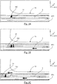
- the Figure 4A illustrates an example of the shape of the front 31 and rear 32 tracks of this lower shuttle 3.
- the front track 31 comprises a rectilinear portion 311, extending parallel to the sliding axis and corresponds to the closed position of the front edge of the movable panel 12. It also comprises an inclined portion 312 forming, with respect to this axis of sliding, an angle ⁇ of the order of 25 °. This inclined portion 312 makes it possible to control the change of position of the front edge of the movable panel 12.
- the rear track 32 also comprises an inclined portion 321 forming, with respect to this sliding axis, an angle ⁇ of the order of 25 °.
- This inclined portion 321 makes it possible to control the change of position of the rear edge of the movable panel. It also comprises a rectilinear portion 322 extending parallel to the axis of sliding.
- the pins 182 carried by the lower edge of the movable panel 12 are, in the closed or closed position of the movable panel 12, abutting the closed end of the rectilinear portion 311 of the front track 31 and abutting the closed end of the inclined portion 321 of the rear track 32.
- the upper shuttle 3 has the same front and rear tracks as the lower shuttle, pins 182 carried by the upper edge of the movable panel 12 cooperating with each of these tracks 31, 32.
- the front 31 and rear 32 tracks are of distinct shapes and symmetrical with respect to a central point located equidistant from the front 31 and rear 32 tracks.
- the lower and upper pawns 182 of the movable panel 12 then move in the front and rear tracks of the lower and upper shuttles.
- the pin 182 cooperating with the front track 31 has moved along the rectilinear portion 311, while the pin 182 cooperating with the rear track 32 has moved in the inclined portion 321 immediately and gradually shifting the rear edge Y of the mobile panel 12 (the same kinematics applying for the upper shuttle).
- the front edge of the movable panel 12 remains in the plane of the fixed panel 11 and therefore does not shift Y, the pin 182 cooperating with the front track 31 moving along the rectilinear portion 311.
- the pins 182 carried by the lower edge of the movable panel 12 are, in the open position of the movable panel, in abutment with the closed end of the inclined portion 312 of the front track 31, as illustrated on FIG. figure 3B , and abutting the closed end of the rectilinear portion 322 of the rear track 32.
- the opening is over.
- the movable panel 12 is in an intermediate position of release, that is to say, it is found in the sliding plane, parallel to the fixed window 11, and opposite the opening in the latter.
- the movable panel 12 slides along the rails 114, 115 to an extreme position called maximum opening.
- the motor and the sliding movable panel 12 can stop in any intermediate sliding position.
- the passage from an open position to the closed position is done symmetrically (from the figure 3C to the figure 3A ).
- the motor moves the shuttles from left to right and once the movable panel 12 located opposite the opening, the front edge of the movable panel 12 shifts Y, then the rear edge.
- the Figure 4B shows the shape of the front 31 and rear 32 tracks of the lower shuttle 3 according to an alternative embodiment.
- the front track 31 comprises an inclined portion 311 forming, with respect to this sliding axis, an angle ⁇ of the order of 25 °.
- This inclined portion 311 controls the change of position of the front edge of the movable panel 12. It also comprises a rectilinear portion 312 extending parallel to the axis of sliding.
- the rear track 32 comprises a rectilinear portion 321, extending parallel to the sliding axis and corresponds to the closed position of the front edge of the movable panel. It also comprises an inclined portion 322 forming, with respect to this sliding axis, an angle ⁇ of the order of 25 °. This inclined portion 322 makes it possible to control the change of position of the rear edge of the movable panel 12.
- the interior of the vehicle can be ventilated by depression when the vehicle is in motion (with an effect similar to the airlocked position of ventilation, called "tilt" in English, of a sunroof).
- the invention thus allows a gradual takeoff of the seal.
- the seal is taken off on one side first of the movable panel 12 to decompress the seal, then on the other side.
- the closed end of the inclined portion 312 of the front track 31 may be slightly offset from that shown in solid lines on the Figure 4A .
- the angle of inclination ⁇ 'of the inclined portion 312 shown in dotted lines is thus equal to 28 ° instead of 25 °.
- the angle of inclination ⁇ 'of the inclined portion 322 of the rear track 32 shown in dashed lines is equal to 28 ° instead of 25 °.
- each shuttle for each guide rail, comprises two fixed pins adapted to cooperate with two grooves carried by an edge of said movable panel.
- the corresponding shuttle for the upper rail, carries two fixed pins adapted to cooperate with two grooves carried by the upper edge of the movable panel.
- the corresponding shuttle for the lower rail, carries two fixed pins adapted to cooperate with two grooves carried by the lower edge of the movable panel.
- the displacement of the movable panel is optimized using synchronization means ensuring the displacement of the upper and lower shuttles synchronously under the action of a single command.
- the invention can also be implemented, of course, in the absence of such synchronization means.
- These synchronization means may for example comprise at least one cable or a foil
- This movement of the shuttles can also be motorized, the electric cable control acting on one of the shuttles which through the synchronization means ensures the movement of the other shuttle.
- the invention can be applied in the same way to other structures having a wall in which is defined a bay, such as, for example, a caravan or a camper.
- the bay may be formed in a side wall of the vehicle (for example for commercial vehicles, minivans, station wagons, ...), in a wall facing the rear of the vehicle (for example for "pick- up "), or in a door.
- the Figure 5A illustrates another example of shape of the front tracks 41 and 42 rear of the lower shuttle 3.
- the Figure 5B illustrates the shape of the front 41 and rear 42 tracks of the upper shuttle 3.
- each track 41, 42 is identical.
- Each track thus comprises a rectilinear portion extending parallel to the sliding axis and a portion inclined with respect to the sliding axis.
- the intermediate position (upper open edge) allows to ventilate the vehicle at a standstill while protecting the interior of the vehicle from light rain.
Landscapes
- Engineering & Computer Science (AREA)
- Mechanical Engineering (AREA)
- Power-Operated Mechanisms For Wings (AREA)
Priority Applications (1)
| Application Number | Priority Date | Filing Date | Title |
|---|---|---|---|
| EP18169047.0A EP3560741B1 (de) | 2018-04-24 | 2018-04-24 | Vorrichtung zur abdichtung eines in die karosserie eines fahrzeugs eingelassenen öffnungsfelds, und entsprechendes fahrzeug |
Applications Claiming Priority (1)
| Application Number | Priority Date | Filing Date | Title |
|---|---|---|---|
| EP18169047.0A EP3560741B1 (de) | 2018-04-24 | 2018-04-24 | Vorrichtung zur abdichtung eines in die karosserie eines fahrzeugs eingelassenen öffnungsfelds, und entsprechendes fahrzeug |
Publications (2)
| Publication Number | Publication Date |
|---|---|
| EP3560741A1 true EP3560741A1 (de) | 2019-10-30 |
| EP3560741B1 EP3560741B1 (de) | 2020-09-30 |
Family
ID=62062933
Family Applications (1)
| Application Number | Title | Priority Date | Filing Date |
|---|---|---|---|
| EP18169047.0A Active EP3560741B1 (de) | 2018-04-24 | 2018-04-24 | Vorrichtung zur abdichtung eines in die karosserie eines fahrzeugs eingelassenen öffnungsfelds, und entsprechendes fahrzeug |
Country Status (1)
| Country | Link |
|---|---|
| EP (1) | EP3560741B1 (de) |
Citations (6)
| Publication number | Priority date | Publication date | Assignee | Title |
|---|---|---|---|---|
| EP0778168A1 (de) | 1995-12-08 | 1997-06-11 | FARNIER & PENIN SNC | An einer Fahrzeugöffnung anliegende Schliessvorrichtung |
| EP0857844A1 (de) | 1997-02-10 | 1998-08-12 | Wagon Automotive | Führungsvorrichtung für einen Öffnungsabschluss-Schwenk-Schiebeflügel |
| FR2833213A1 (fr) * | 2001-12-10 | 2003-06-13 | Wagon Automotive Snc | Dispositif d'obturation d'une baie menagee dans un vehicule a rail de coulissement unique, et vehicule correspondant |
| FR2924739A1 (fr) * | 2007-12-10 | 2009-06-12 | Wagon Sas | Dispositif d'obturation d'une baie menagee dans la carrosserie d'un vehicule, a element de guidage et coulisseau formant navette, et vehicule correspondant |
| FR2963282A1 (fr) * | 2010-07-30 | 2012-02-03 | Acs France Sas | Dispositif d'obturation d'une baie menagee dans le toit d'un vehicule automobile, apte a etre place dans une position d'obturation partielle |
| EP2479366A2 (de) * | 2011-01-19 | 2012-07-25 | Advanced Comfort Systems France SAS - ACS France | Schliessvorrichtung einer Öffnung eines Kraftfahrzeugs |
-
2018
- 2018-04-24 EP EP18169047.0A patent/EP3560741B1/de active Active
Patent Citations (6)
| Publication number | Priority date | Publication date | Assignee | Title |
|---|---|---|---|---|
| EP0778168A1 (de) | 1995-12-08 | 1997-06-11 | FARNIER & PENIN SNC | An einer Fahrzeugöffnung anliegende Schliessvorrichtung |
| EP0857844A1 (de) | 1997-02-10 | 1998-08-12 | Wagon Automotive | Führungsvorrichtung für einen Öffnungsabschluss-Schwenk-Schiebeflügel |
| FR2833213A1 (fr) * | 2001-12-10 | 2003-06-13 | Wagon Automotive Snc | Dispositif d'obturation d'une baie menagee dans un vehicule a rail de coulissement unique, et vehicule correspondant |
| FR2924739A1 (fr) * | 2007-12-10 | 2009-06-12 | Wagon Sas | Dispositif d'obturation d'une baie menagee dans la carrosserie d'un vehicule, a element de guidage et coulisseau formant navette, et vehicule correspondant |
| FR2963282A1 (fr) * | 2010-07-30 | 2012-02-03 | Acs France Sas | Dispositif d'obturation d'une baie menagee dans le toit d'un vehicule automobile, apte a etre place dans une position d'obturation partielle |
| EP2479366A2 (de) * | 2011-01-19 | 2012-07-25 | Advanced Comfort Systems France SAS - ACS France | Schliessvorrichtung einer Öffnung eines Kraftfahrzeugs |
Also Published As
| Publication number | Publication date |
|---|---|
| EP3560741B1 (de) | 2020-09-30 |
Similar Documents
| Publication | Publication Date | Title |
|---|---|---|
| EP2442993B1 (de) | Vorrichtung zum schliessen einer in die karosserie eines fahrzeugs eingelassenen öffnung mit ausgleichsmitteln, und entsprechendes kraftfahrzeug | |
| EP0857844A1 (de) | Führungsvorrichtung für einen Öffnungsabschluss-Schwenk-Schiebeflügel | |
| EP1939384B1 (de) | Vorrichtung zur Abdichtung eines in die Karosserie eines Fahrzeugs eingelassenen Öffnungsfelds mit Hilfe eines beweglichen Metallstücks, das einen Verschlussriegel bildet, und entsprechendes Kraftfahrzeug | |
| EP2479366B1 (de) | Schliessvorrichtung einer Öffnung eines Kraftfahrzeugs | |
| EP4472852A1 (de) | Vorrichtung zum verschliessen einer öffnung in der karosserie eines fahrzeugs und entsprechendes fahrzeug | |
| EP3967531B1 (de) | Vorrichtung zur abdichtung eines in die karosserie eines fahrzeugs eingelassenen öffnungsfelds, und entsprechendes fahrzeug | |
| WO2023147865A1 (fr) | Dispositif d'obturation d'une baie menagee dans la carrosserie d'un vehicule, et vehicule correspondant | |
| FR3021254A1 (fr) | Dispositif vitre affleurant pour porte de vehicule a panneau mobile reglable, porte et vehicule automobile correspondants. | |
| EP3560741B1 (de) | Vorrichtung zur abdichtung eines in die karosserie eines fahrzeugs eingelassenen öffnungsfelds, und entsprechendes fahrzeug | |
| FR2833209A1 (fr) | Dispositif d'obturation d'une baie menagee dans la carrosserie d'un vehicule, et vehicule correspondant | |
| EP4124484B1 (de) | Vorrichtung zum verschliessen eines in die karosserie eines fahrzeugs eingelassenen öffnungsfelds und entsprechendes fahrzeug | |
| EP2089245B1 (de) | Heckklappenkonstruktion für ein automobil und automobil mit derartiger konstruktion | |
| FR2833212A1 (fr) | Dispositif d'obturation d'une baie menagee dans un vehicule a rail de coulissement unique, et vehicule correspondant | |
| EP1433633B1 (de) | Schliesseinrichtung einer Öffnung in einem Fahrzeug und zugehöriges Fahrzeug | |
| EP1323557B1 (de) | Schliesseinrichtung einer Fahrzeugöffnung mit einer rotatorisch beweglichen Scheibe und zugehörigem Fahrzeug | |
| EP1323558B1 (de) | Motorisch betriebene Schliesseinrichtung einer Öffnung in einem Fahrzeug und zugehöriges Fahrzeug | |
| FR2833213A1 (fr) | Dispositif d'obturation d'une baie menagee dans un vehicule a rail de coulissement unique, et vehicule correspondant | |
| EP2263895B1 (de) | Vorrichtung zum Schliessen einer Öffnung in der Karosserie eines Fahrzeugs mit Ausgleichsmitteln, und Kraftfahrzeug mit einer solchen Vorrichtung | |
| EP4720446A1 (de) | Vorrichtung zum schliessen der öffnung eines gestuften schienenfensters, und entsprechendes fahrzeug | |
| FR3149239A1 (fr) | Dispositif d'obturation d'une baie à rail étagé, et véhicule correspondant. | |
| FR2881687A1 (fr) | Dispositif d'occultation pour pavillon vitre a actionnement manuel ou electrique | |
| EP2457756A1 (de) | Verglaster Pavillon mit beweglichen Schiebe- und Öffnungspaneelen | |
| FR2983129A1 (fr) | Pavillon vitre a panneau mobile coulissant et entrebaillant. | |
| FR2546955A1 (fr) | Agencement de panneau, notamment porte ou fenetre, du type relevable-coulissant et apllication d'un tel agencement aux cabines de vehicules, tels que tracteurs ou analogues | |
| EP1598513A1 (de) | Fahrzeugtür mit Schiebefenster. |
Legal Events
| Date | Code | Title | Description |
|---|---|---|---|
| PUAI | Public reference made under article 153(3) epc to a published international application that has entered the european phase |
Free format text: ORIGINAL CODE: 0009012 |
|
| STAA | Information on the status of an ep patent application or granted ep patent |
Free format text: STATUS: THE APPLICATION HAS BEEN PUBLISHED |
|
| AK | Designated contracting states |
Kind code of ref document: A1 Designated state(s): AL AT BE BG CH CY CZ DE DK EE ES FI FR GB GR HR HU IE IS IT LI LT LU LV MC MK MT NL NO PL PT RO RS SE SI SK SM TR |
|
| AX | Request for extension of the european patent |
Extension state: BA ME |
|
| STAA | Information on the status of an ep patent application or granted ep patent |
Free format text: STATUS: REQUEST FOR EXAMINATION WAS MADE |
|
| 17P | Request for examination filed |
Effective date: 20191203 |
|
| RBV | Designated contracting states (corrected) |
Designated state(s): AL AT BE BG CH CY CZ DE DK EE ES FI FR GB GR HR HU IE IS IT LI LT LU LV MC MK MT NL NO PL PT RO RS SE SI SK SM TR |
|
| GRAP | Despatch of communication of intention to grant a patent |
Free format text: ORIGINAL CODE: EPIDOSNIGR1 |
|
| STAA | Information on the status of an ep patent application or granted ep patent |
Free format text: STATUS: GRANT OF PATENT IS INTENDED |
|
| INTG | Intention to grant announced |
Effective date: 20200626 |
|
| GRAS | Grant fee paid |
Free format text: ORIGINAL CODE: EPIDOSNIGR3 |
|
| GRAA | (expected) grant |
Free format text: ORIGINAL CODE: 0009210 |
|
| STAA | Information on the status of an ep patent application or granted ep patent |
Free format text: STATUS: THE PATENT HAS BEEN GRANTED |
|
| AK | Designated contracting states |
Kind code of ref document: B1 Designated state(s): AL AT BE BG CH CY CZ DE DK EE ES FI FR GB GR HR HU IE IS IT LI LT LU LV MC MK MT NL NO PL PT RO RS SE SI SK SM TR |
|
| REG | Reference to a national code |
Ref country code: CH Ref legal event code: EP Ref country code: GB Ref legal event code: FG4D Free format text: NOT ENGLISH |
|
| REG | Reference to a national code |
Ref country code: DE Ref legal event code: R096 Ref document number: 602018008199 Country of ref document: DE Ref country code: AT Ref legal event code: REF Ref document number: 1318448 Country of ref document: AT Kind code of ref document: T Effective date: 20201015 |
|
| REG | Reference to a national code |
Ref country code: IE Ref legal event code: FG4D Free format text: LANGUAGE OF EP DOCUMENT: FRENCH |
|
| PG25 | Lapsed in a contracting state [announced via postgrant information from national office to epo] |
Ref country code: SE Free format text: LAPSE BECAUSE OF FAILURE TO SUBMIT A TRANSLATION OF THE DESCRIPTION OR TO PAY THE FEE WITHIN THE PRESCRIBED TIME-LIMIT Effective date: 20200930 Ref country code: NO Free format text: LAPSE BECAUSE OF FAILURE TO SUBMIT A TRANSLATION OF THE DESCRIPTION OR TO PAY THE FEE WITHIN THE PRESCRIBED TIME-LIMIT Effective date: 20201230 Ref country code: FI Free format text: LAPSE BECAUSE OF FAILURE TO SUBMIT A TRANSLATION OF THE DESCRIPTION OR TO PAY THE FEE WITHIN THE PRESCRIBED TIME-LIMIT Effective date: 20200930 Ref country code: HR Free format text: LAPSE BECAUSE OF FAILURE TO SUBMIT A TRANSLATION OF THE DESCRIPTION OR TO PAY THE FEE WITHIN THE PRESCRIBED TIME-LIMIT Effective date: 20200930 Ref country code: BG Free format text: LAPSE BECAUSE OF FAILURE TO SUBMIT A TRANSLATION OF THE DESCRIPTION OR TO PAY THE FEE WITHIN THE PRESCRIBED TIME-LIMIT Effective date: 20201230 |
|
| REG | Reference to a national code |
Ref country code: AT Ref legal event code: MK05 Ref document number: 1318448 Country of ref document: AT Kind code of ref document: T Effective date: 20200930 |
|
| PG25 | Lapsed in a contracting state [announced via postgrant information from national office to epo] |
Ref country code: RS Free format text: LAPSE BECAUSE OF FAILURE TO SUBMIT A TRANSLATION OF THE DESCRIPTION OR TO PAY THE FEE WITHIN THE PRESCRIBED TIME-LIMIT Effective date: 20200930 Ref country code: LV Free format text: LAPSE BECAUSE OF FAILURE TO SUBMIT A TRANSLATION OF THE DESCRIPTION OR TO PAY THE FEE WITHIN THE PRESCRIBED TIME-LIMIT Effective date: 20200930 |
|
| REG | Reference to a national code |
Ref country code: NL Ref legal event code: MP Effective date: 20200930 |
|
| REG | Reference to a national code |
Ref country code: LT Ref legal event code: MG4D |
|
| PG25 | Lapsed in a contracting state [announced via postgrant information from national office to epo] |
Ref country code: LT Free format text: LAPSE BECAUSE OF FAILURE TO SUBMIT A TRANSLATION OF THE DESCRIPTION OR TO PAY THE FEE WITHIN THE PRESCRIBED TIME-LIMIT Effective date: 20200930 Ref country code: SM Free format text: LAPSE BECAUSE OF FAILURE TO SUBMIT A TRANSLATION OF THE DESCRIPTION OR TO PAY THE FEE WITHIN THE PRESCRIBED TIME-LIMIT Effective date: 20200930 Ref country code: EE Free format text: LAPSE BECAUSE OF FAILURE TO SUBMIT A TRANSLATION OF THE DESCRIPTION OR TO PAY THE FEE WITHIN THE PRESCRIBED TIME-LIMIT Effective date: 20200930 Ref country code: PT Free format text: LAPSE BECAUSE OF FAILURE TO SUBMIT A TRANSLATION OF THE DESCRIPTION OR TO PAY THE FEE WITHIN THE PRESCRIBED TIME-LIMIT Effective date: 20210201 Ref country code: RO Free format text: LAPSE BECAUSE OF FAILURE TO SUBMIT A TRANSLATION OF THE DESCRIPTION OR TO PAY THE FEE WITHIN THE PRESCRIBED TIME-LIMIT Effective date: 20200930 Ref country code: CZ Free format text: LAPSE BECAUSE OF FAILURE TO SUBMIT A TRANSLATION OF THE DESCRIPTION OR TO PAY THE FEE WITHIN THE PRESCRIBED TIME-LIMIT Effective date: 20200930 |
|
| PG25 | Lapsed in a contracting state [announced via postgrant information from national office to epo] |
Ref country code: PL Free format text: LAPSE BECAUSE OF FAILURE TO SUBMIT A TRANSLATION OF THE DESCRIPTION OR TO PAY THE FEE WITHIN THE PRESCRIBED TIME-LIMIT Effective date: 20200930 Ref country code: IS Free format text: LAPSE BECAUSE OF FAILURE TO SUBMIT A TRANSLATION OF THE DESCRIPTION OR TO PAY THE FEE WITHIN THE PRESCRIBED TIME-LIMIT Effective date: 20210130 Ref country code: AT Free format text: LAPSE BECAUSE OF FAILURE TO SUBMIT A TRANSLATION OF THE DESCRIPTION OR TO PAY THE FEE WITHIN THE PRESCRIBED TIME-LIMIT Effective date: 20200930 Ref country code: AL Free format text: LAPSE BECAUSE OF FAILURE TO SUBMIT A TRANSLATION OF THE DESCRIPTION OR TO PAY THE FEE WITHIN THE PRESCRIBED TIME-LIMIT Effective date: 20200930 Ref country code: ES Free format text: LAPSE BECAUSE OF FAILURE TO SUBMIT A TRANSLATION OF THE DESCRIPTION OR TO PAY THE FEE WITHIN THE PRESCRIBED TIME-LIMIT Effective date: 20200930 |
|
| PG25 | Lapsed in a contracting state [announced via postgrant information from national office to epo] |
Ref country code: SK Free format text: LAPSE BECAUSE OF FAILURE TO SUBMIT A TRANSLATION OF THE DESCRIPTION OR TO PAY THE FEE WITHIN THE PRESCRIBED TIME-LIMIT Effective date: 20200930 Ref country code: NL Free format text: LAPSE BECAUSE OF FAILURE TO SUBMIT A TRANSLATION OF THE DESCRIPTION OR TO PAY THE FEE WITHIN THE PRESCRIBED TIME-LIMIT Effective date: 20200930 |
|
| REG | Reference to a national code |
Ref country code: DE Ref legal event code: R097 Ref document number: 602018008199 Country of ref document: DE |
|
| PLBE | No opposition filed within time limit |
Free format text: ORIGINAL CODE: 0009261 |
|
| STAA | Information on the status of an ep patent application or granted ep patent |
Free format text: STATUS: NO OPPOSITION FILED WITHIN TIME LIMIT |
|
| PG25 | Lapsed in a contracting state [announced via postgrant information from national office to epo] |
Ref country code: DK Free format text: LAPSE BECAUSE OF FAILURE TO SUBMIT A TRANSLATION OF THE DESCRIPTION OR TO PAY THE FEE WITHIN THE PRESCRIBED TIME-LIMIT Effective date: 20200930 |
|
| 26N | No opposition filed |
Effective date: 20210701 |
|
| PG25 | Lapsed in a contracting state [announced via postgrant information from national office to epo] |
Ref country code: IT Free format text: LAPSE BECAUSE OF FAILURE TO SUBMIT A TRANSLATION OF THE DESCRIPTION OR TO PAY THE FEE WITHIN THE PRESCRIBED TIME-LIMIT Effective date: 20200930 |
|
| PG25 | Lapsed in a contracting state [announced via postgrant information from national office to epo] |
Ref country code: SI Free format text: LAPSE BECAUSE OF FAILURE TO SUBMIT A TRANSLATION OF THE DESCRIPTION OR TO PAY THE FEE WITHIN THE PRESCRIBED TIME-LIMIT Effective date: 20200930 Ref country code: MC Free format text: LAPSE BECAUSE OF FAILURE TO SUBMIT A TRANSLATION OF THE DESCRIPTION OR TO PAY THE FEE WITHIN THE PRESCRIBED TIME-LIMIT Effective date: 20200930 |
|
| PG25 | Lapsed in a contracting state [announced via postgrant information from national office to epo] |
Ref country code: LU Free format text: LAPSE BECAUSE OF NON-PAYMENT OF DUE FEES Effective date: 20210424 |
|
| REG | Reference to a national code |
Ref country code: BE Ref legal event code: MM Effective date: 20210430 |
|
| PG25 | Lapsed in a contracting state [announced via postgrant information from national office to epo] |
Ref country code: FR Free format text: LAPSE BECAUSE OF NON-PAYMENT OF DUE FEES Effective date: 20210430 Ref country code: LI Free format text: LAPSE BECAUSE OF NON-PAYMENT OF DUE FEES Effective date: 20210430 Ref country code: CH Free format text: LAPSE BECAUSE OF NON-PAYMENT OF DUE FEES Effective date: 20210430 |
|
| PG25 | Lapsed in a contracting state [announced via postgrant information from national office to epo] |
Ref country code: IE Free format text: LAPSE BECAUSE OF NON-PAYMENT OF DUE FEES Effective date: 20210424 |
|
| PG25 | Lapsed in a contracting state [announced via postgrant information from national office to epo] |
Ref country code: IS Free format text: LAPSE BECAUSE OF FAILURE TO SUBMIT A TRANSLATION OF THE DESCRIPTION OR TO PAY THE FEE WITHIN THE PRESCRIBED TIME-LIMIT Effective date: 20210130 |
|
| PG25 | Lapsed in a contracting state [announced via postgrant information from national office to epo] |
Ref country code: BE Free format text: LAPSE BECAUSE OF NON-PAYMENT OF DUE FEES Effective date: 20210430 |
|
| GBPC | Gb: european patent ceased through non-payment of renewal fee |
Effective date: 20220424 |
|
| PG25 | Lapsed in a contracting state [announced via postgrant information from national office to epo] |
Ref country code: GB Free format text: LAPSE BECAUSE OF NON-PAYMENT OF DUE FEES Effective date: 20220424 |
|
| PG25 | Lapsed in a contracting state [announced via postgrant information from national office to epo] |
Ref country code: CY Free format text: LAPSE BECAUSE OF FAILURE TO SUBMIT A TRANSLATION OF THE DESCRIPTION OR TO PAY THE FEE WITHIN THE PRESCRIBED TIME-LIMIT Effective date: 20200930 |
|
| P01 | Opt-out of the competence of the unified patent court (upc) registered |
Effective date: 20230527 |
|
| PG25 | Lapsed in a contracting state [announced via postgrant information from national office to epo] |
Ref country code: HU Free format text: LAPSE BECAUSE OF FAILURE TO SUBMIT A TRANSLATION OF THE DESCRIPTION OR TO PAY THE FEE WITHIN THE PRESCRIBED TIME-LIMIT; INVALID AB INITIO Effective date: 20180424 Ref country code: GR Free format text: LAPSE BECAUSE OF FAILURE TO SUBMIT A TRANSLATION OF THE DESCRIPTION OR TO PAY THE FEE WITHIN THE PRESCRIBED TIME-LIMIT Effective date: 20200930 |
|
| PG25 | Lapsed in a contracting state [announced via postgrant information from national office to epo] |
Ref country code: MK Free format text: LAPSE BECAUSE OF FAILURE TO SUBMIT A TRANSLATION OF THE DESCRIPTION OR TO PAY THE FEE WITHIN THE PRESCRIBED TIME-LIMIT Effective date: 20200930 |
|
| PG25 | Lapsed in a contracting state [announced via postgrant information from national office to epo] |
Ref country code: MT Free format text: LAPSE BECAUSE OF FAILURE TO SUBMIT A TRANSLATION OF THE DESCRIPTION OR TO PAY THE FEE WITHIN THE PRESCRIBED TIME-LIMIT Effective date: 20200930 |
|
| PGFP | Annual fee paid to national office [announced via postgrant information from national office to epo] |
Ref country code: DE Payment date: 20250429 Year of fee payment: 8 |
|
| PG25 | Lapsed in a contracting state [announced via postgrant information from national office to epo] |
Ref country code: TR Free format text: LAPSE BECAUSE OF FAILURE TO SUBMIT A TRANSLATION OF THE DESCRIPTION OR TO PAY THE FEE WITHIN THE PRESCRIBED TIME-LIMIT Effective date: 20200930 |