EP3561464B1 - Détection discrète et automatisée de fréquences de parties distinctes spatialement localisées d'une machine - Google Patents
Détection discrète et automatisée de fréquences de parties distinctes spatialement localisées d'une machine Download PDFInfo
- Publication number
- EP3561464B1 EP3561464B1 EP19151159.1A EP19151159A EP3561464B1 EP 3561464 B1 EP3561464 B1 EP 3561464B1 EP 19151159 A EP19151159 A EP 19151159A EP 3561464 B1 EP3561464 B1 EP 3561464B1
- Authority
- EP
- European Patent Office
- Prior art keywords
- vibration frequency
- frequency
- video
- vibration
- vibrating part
- Prior art date
- Legal status (The legal status is an assumption and is not a legal conclusion. Google has not performed a legal analysis and makes no representation as to the accuracy of the status listed.)
- Active
Links
Images



Classifications
-
- G—PHYSICS
- G01—MEASURING; TESTING
- G01M—TESTING STATIC OR DYNAMIC BALANCE OF MACHINES OR STRUCTURES; TESTING OF STRUCTURES OR APPARATUS, NOT OTHERWISE PROVIDED FOR
- G01M13/00—Testing of machine parts
- G01M13/02—Gearings; Transmission mechanisms
- G01M13/028—Acoustic or vibration analysis
-
- G—PHYSICS
- G01—MEASURING; TESTING
- G01H—MEASUREMENT OF MECHANICAL VIBRATIONS OR ULTRASONIC, SONIC OR INFRASONIC WAVES
- G01H9/00—Measuring mechanical vibrations or ultrasonic, sonic or infrasonic waves by using radiation-sensitive means, e.g. optical means
-
- G—PHYSICS
- G01—MEASURING; TESTING
- G01N—INVESTIGATING OR ANALYSING MATERIALS BY DETERMINING THEIR CHEMICAL OR PHYSICAL PROPERTIES
- G01N29/00—Investigating or analysing materials by the use of ultrasonic, sonic or infrasonic waves; Visualisation of the interior of objects by transmitting ultrasonic or sonic waves through the object
- G01N29/44—Processing the detected response signal, e.g. electronic circuits specially adapted therefor
- G01N29/46—Processing the detected response signal, e.g. electronic circuits specially adapted therefor by spectral analysis, e.g. Fourier analysis or wavelet analysis
-
- G—PHYSICS
- G01—MEASURING; TESTING
- G01S—RADIO DIRECTION-FINDING; RADIO NAVIGATION; DETERMINING DISTANCE OR VELOCITY BY USE OF RADIO WAVES; LOCATING OR PRESENCE-DETECTING BY USE OF THE REFLECTION OR RERADIATION OF RADIO WAVES; ANALOGOUS ARRANGEMENTS USING OTHER WAVES
- G01S13/00—Systems using the reflection or reradiation of radio waves, e.g. radar systems; Analogous systems using reflection or reradiation of waves whose nature or wavelength is irrelevant or unspecified
- G01S13/02—Systems using reflection of radio waves, e.g. primary radar systems; Analogous systems
- G01S13/50—Systems of measurement based on relative movement of target
-
- G—PHYSICS
- G01—MEASURING; TESTING
- G01S—RADIO DIRECTION-FINDING; RADIO NAVIGATION; DETERMINING DISTANCE OR VELOCITY BY USE OF RADIO WAVES; LOCATING OR PRESENCE-DETECTING BY USE OF THE REFLECTION OR RERADIATION OF RADIO WAVES; ANALOGOUS ARRANGEMENTS USING OTHER WAVES
- G01S13/00—Systems using the reflection or reradiation of radio waves, e.g. radar systems; Analogous systems using reflection or reradiation of waves whose nature or wavelength is irrelevant or unspecified
- G01S13/02—Systems using reflection of radio waves, e.g. primary radar systems; Analogous systems
- G01S13/50—Systems of measurement based on relative movement of target
- G01S13/52—Discriminating between fixed and moving objects or between objects moving at different speeds
-
- G—PHYSICS
- G01—MEASURING; TESTING
- G01S—RADIO DIRECTION-FINDING; RADIO NAVIGATION; DETERMINING DISTANCE OR VELOCITY BY USE OF RADIO WAVES; LOCATING OR PRESENCE-DETECTING BY USE OF THE REFLECTION OR RERADIATION OF RADIO WAVES; ANALOGOUS ARRANGEMENTS USING OTHER WAVES
- G01S13/00—Systems using the reflection or reradiation of radio waves, e.g. radar systems; Analogous systems using reflection or reradiation of waves whose nature or wavelength is irrelevant or unspecified
- G01S13/86—Combinations of radar systems with non-radar systems, e.g. sonar, direction finder
- G01S13/867—Combination of radar systems with cameras
-
- G—PHYSICS
- G01—MEASURING; TESTING
- G01S—RADIO DIRECTION-FINDING; RADIO NAVIGATION; DETERMINING DISTANCE OR VELOCITY BY USE OF RADIO WAVES; LOCATING OR PRESENCE-DETECTING BY USE OF THE REFLECTION OR RERADIATION OF RADIO WAVES; ANALOGOUS ARRANGEMENTS USING OTHER WAVES
- G01S15/00—Systems using the reflection or reradiation of acoustic waves, e.g. sonar systems
- G01S15/02—Systems using the reflection or reradiation of acoustic waves, e.g. sonar systems using reflection of acoustic waves
- G01S15/50—Systems of measurement, based on relative movement of the target
-
- G—PHYSICS
- G01—MEASURING; TESTING
- G01S—RADIO DIRECTION-FINDING; RADIO NAVIGATION; DETERMINING DISTANCE OR VELOCITY BY USE OF RADIO WAVES; LOCATING OR PRESENCE-DETECTING BY USE OF THE REFLECTION OR RERADIATION OF RADIO WAVES; ANALOGOUS ARRANGEMENTS USING OTHER WAVES
- G01S15/00—Systems using the reflection or reradiation of acoustic waves, e.g. sonar systems
- G01S15/02—Systems using the reflection or reradiation of acoustic waves, e.g. sonar systems using reflection of acoustic waves
- G01S15/50—Systems of measurement, based on relative movement of the target
- G01S15/52—Discriminating between fixed and moving objects or between objects moving at different speeds
-
- G—PHYSICS
- G01—MEASURING; TESTING
- G01S—RADIO DIRECTION-FINDING; RADIO NAVIGATION; DETERMINING DISTANCE OR VELOCITY BY USE OF RADIO WAVES; LOCATING OR PRESENCE-DETECTING BY USE OF THE REFLECTION OR RERADIATION OF RADIO WAVES; ANALOGOUS ARRANGEMENTS USING OTHER WAVES
- G01S17/00—Systems using the reflection or reradiation of electromagnetic waves other than radio waves, e.g. lidar systems
- G01S17/02—Systems using the reflection of electromagnetic waves other than radio waves
- G01S17/50—Systems of measurement based on relative movement of target
Definitions
- the disclosure herein generally relates to vibration detection, and, more particularly, to unobtrusive and automated detection of frequencies of spatially located distinct parts of a machine.
- a typical workstation has a collection of different vibrating or moving parts or has a large machine body with spatially distributed vibrating zones or parts. To detect the exact location and frequency of this vibration is crucial for both routine monitoring and fault detection.
- Current solutions use either high frames per second (fps) industrial grade camera or stroboscopes tuned at one particular frequency. Manual stroboscopes are also in use, which require manual intervention for objects moving at different speeds with high convergence time. Point-lasers are also in use, for which prior knowledge of exact location of faults are to be known. Also Point-by-point scanning of a large machine body takes up a lot of time.
- Embodiments of the present disclosure present technological improvements as solutions to one or more of the above-mentioned technical problems recognized by the inventors in conventional systems.
- a processor implemented method comprising: detecting, by a movement detector, a set of vibration frequencies, each vibration frequency in the set of vibration frequencies corresponding to a vibrating part from a plurality of vibrating parts in a machine under inspection in a field of view (FOV) of the movement detector, each of the plurality of vibrating parts having a pre-defined marker for tracking the vibrating part associated thereof; and initiating, by a stroboscope, strobing at each vibration frequency from the set of vibration frequencies, starting at a first detected vibration frequency, the step of strobing at each vibration frequency comprising: recording an output of the stroboscope in the form of a video having a pre-determined length; and extracting from the video, at least one frame having a vibrating part corresponding to an associated vibration frequency, and mapping each vibration frequency detected by the movement detector to a corresponding vibrating part using the pre-defined marker.
- FOV field of view
- a system comprising: one or more data storage devices operatively coupled to the one or more processors and configured to store instructions configured for execution by the one or more processors to: receive a set of vibration frequencies, from a movement detector, each vibration frequency in the set of vibration frequencies corresponding to a vibrating part from a plurality of vibrating parts in a machine under inspection in a field of view (FOV) of the movement detector, each of the plurality of vibrating parts having a pre-defined marker for tracking the vibrating part associated thereof; trigger a stroboscope to initiate strobing at each vibration frequency from the set of vibration frequencies, starting at a first detected vibration frequency, wherein the step of strobing at each vibration frequency comprises: receiving an output of the stroboscope in the form of a video having a pre-determined length; and extracting from the video, at least one frame having a vibrating part corresponding to an associated vibration frequency, and mapping each vibration frequency detected by the movement detector to a corresponding vibrating part using the pre-
- FOV field of view
- the pre-determined length of the video is based on a trade-off between resolution of the detected vibration frequency and measurement time wherein longer the measurement time better is the resolution of the detected vibration frequency. In an embodiment, the pre-determined length of the video is 1 second.
- the one or more hardware processors are further configured to extract from the video, a frame having a vibrating part by: obtaining a frequency spectrum of displacement of the pre-defined marker between frames comprised in the video using Fast Fourier Transform (FFT); determining a peak frequency from the obtained frequency spectrum; extracting and segmenting the at least one frame if the determined peak frequency is less than a pre-defined threshold based on a pre-defined precision; else incrementally tuning the stroboscope to strobe at frequencies that are multiples of 0.1Hz times a pre-determined tuning parameter until the determined peak frequency is less than the pre-defined threshold and performing the step of extracting and segmenting; and mapping the vibration frequency at which the stroboscope is strobing to a vibrating part associated with the pre-defined marker identified in the segmented at least one frame.
- FFT Fast Fourier Transform
- the pre-determined tuning parameter and the pre-defined threshold are based on a trade-of between resolution of the detected vibration frequency and measurement time.
- a RAdio Detection And Ranging (RADAR) guided stroboscope along with an ordinary 30 fps optical camera provides an automated and cost-effective solution to the industrial problem of performing routine inspection or fault detection in machines having distinct vibrating parts.
- RADAR RAdio Detection And Ranging
- the expressions 'parts' or 'vibrating parts' refer to vibrating or moving parts of a machine or spatially distributed vibrating locations or zones in a machine body.
- the expression 'vibration' in the context of the present disclosure includes rotational and linear vibration.
- FIGS. 1 through 6 where similar reference characters denote corresponding features consistently throughout the figures, there are shown preferred embodiments and these embodiments are described in the context of the following exemplary system and method.
- FIG.1 illustrates an exemplary block diagram of a system 100 for unobtrusive and automated detection of frequencies of spatially located distinct parts of a machine in accordance with an embodiment of the present disclosure.
- the system 100 includes one or more processors 104, communication interface device(s) or input/output (I/O) interface(s) 106, and one or more data storage devices or memory 102 operatively coupled to the one or more processors 104.
- the one or more processors 104 that are hardware processors can be implemented as one or more microprocessors, microcomputers, microcontrollers, digital signal processors, central processing units, state machines, graphics controllers, logic circuitries, and/or any devices that manipulate signals based on operational instructions.
- the processor(s) are configured to fetch and execute computer-readable instructions stored in the memory.
- the expressions 'processors' and 'hardware processors' may be used interchangeably.
- the system 100 can be implemented in a variety of computing systems, such as laptop computers, notebooks, hand-held devices, workstations, mainframe computers, servers, a network cloud and the like.
- the I/O interface(s) 106 can include a variety of software and hardware interfaces, for example, a web interface, a graphical user interface, and the like and can facilitate multiple communications within a wide variety of networks N/W and protocol types, including wired networks, for example, LAN, cable, etc., and wireless networks, such as WLAN, cellular, or satellite.
- the I/O interface(s) can include one or more ports for connecting a number of devices to one another or to another server.
- the memory 102 may include any computer-readable medium known in the art including, for example, volatile memory, such as static random access memory (SRAM) and dynamic random access memory (DRAM), and/or non-volatile memory, such as read only memory (ROM), erasable programmable ROM, flash memories, hard disks, optical disks, and magnetic tapes.
- volatile memory such as static random access memory (SRAM) and dynamic random access memory (DRAM)
- non-volatile memory such as read only memory (ROM), erasable programmable ROM, flash memories, hard disks, optical disks, and magnetic tapes.
- ROM read only memory
- erasable programmable ROM erasable programmable ROM
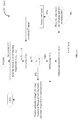
- FIG.2A illustrates an exemplary flow chart 200A for a method for unobtrusive and automated detection of frequencies of spatially located distinct parts of a machine
- FIG.2B is an exemplary flow diagram 200B illustrating a computer implemented method for unobtrusive and automated detection of frequencies of spatially located distinct parts of a machine, in accordance with an embodiment of the present disclosure.
- the system 100 includes one or more data storage devices or memory 102 operatively coupled to the one or more processors 104 and is configured to store instructions configured for execution of steps of the method 200A or 200B by the one or more processors 104.
- the steps of the method 200B will now be explained in detail with reference to the components of the system 100 of FIG.
- the one or more processors 104 are configured to detect by a movement detector (302 of FIG.3 ), at step 202, a set of vibration frequencies wherein each vibration frequency in the set corresponds to a vibrating part from a plurality of vibrating parts in a machine under inspection placed in a field of view (FOV) of the movement detector (302 of FIG.3 ).
- the movement detector is an electromagnetic wave based contactless vibration detector such as RAdio Detection And Ranging (RADAR), SOund Navigation And Ranging (SONAR) and LIght Detection And Ranging (LIDAR).
- RADAR RAdio Detection And Ranging
- SONAR SOund Navigation And Ranging
- LIDAR LIght Detection And Ranging
- a Continuous Wave RADAR may be employed as the movement detector (302 of FIG.3 ).
- the movement detector (302 of FIG.3 ) detects vibration frequencies of all the vibrating parts of the machine under inspection.
- the detected vibration frequencies may
- the one or more processors 104 are configured to initiate strobing by a stroboscope (304 of FIG.3 ), at step 204, strobing at each vibration frequency from the set of vibration frequencies detected by the movement detector (302 of FIG.3 ), starting at a first detected vibration frequency.
- the plurality of vibration frequencies detected by the movement detector (302 of FIG.3 ) helps to reduce the search space of the stroboscope (304 of FIG.3 ) thereby reducing convergence time.
- the step of strobing (204) at each vibration frequency comprises recording an output of the stroboscope (304 of FIG.3 ) by a video capturing device (306 of FIG.3 ), at step 204a, in the form of a video having a pre-determined length.
- the video capturing device (306 of FIG.3 ) is an optical camera.
- the pre-determined length of the video is based on a trade-off between resolution of the detected vibration frequency and measurement time wherein longer the measurement time better is the resolution of the detected vibration frequency.
- the pre-determined length of the video is 1 second.
- the step of strobing (204) aids in identifying the vibrating part corresponding to each vibration frequency detected by the movement detector (302 of FIG.3 ).
- Each of the plurality of vibrating parts has a pre-defined marker for tracking the vibrating part.
- the pre-defined marker may be in the form of an induced mark such as dot or a tick or any other identifiable mark.
- a machine part such as a bolt or a screw head may also serve as the pre-defined marker.
- at step 204b at least one frame having a vibrating part corresponding to each of the detected vibration frequency is extracted from the video.
- the step 204b may further comprise visual inspection of the frames comprised in the video wherein one or more frames wherein the pre-defined marker is static or is not blurred may be identified as the one or more frames depicting the vibrating part that maps to the corresponding vibration frequency.
- the system 100 may execute step 204b in an automated manner wherein firstly a frequency spectrum of displacement of the pre-defined marker between frames comprised in the video is obtained using Fast Fourier Transform (FFT). A peak frequency is then determined from the obtained frequency spectrum. At least one frame comprised in the video may be extracted and segmented for further analyses.
- FFT Fast Fourier Transform
- the corresponding vibration frequency is identified as the frequency of the vibrating part associated with the pre-defined marker in the segmented at least one frame.
- the pre-defined precision is defined on the level of precision matching needed between the strobing frequency and the vibration frequency of the vibrating part.
- the pre-defined threshold may be 0.5Hz.
- the strobing stops and initiates at a next detected vibration frequency by the movement detector (302 of FIG.3 ); else, the stroboscope (304 of FIG.3 ) is incrementally tuned at frequencies that are multiples of 0.1Hz times a pre-determined tuning parameter ( ⁇ ) until the determined peak frequency is less than the pre-defined threshold and the step of extracting and segmenting is repeated.
- the vibration frequency at which the stroboscope is strobing is mapped to a vibrating part associated with the pre-defined marker identified in the segmented at least one frame.
- the pre-determined tuning parameter and the pre-defined threshold are based on a trade-of between resolution of the detected vibration frequency and measurement time. Images of all vibrating parts corresponding to each vibration frequency detected by the movement detector (302 of FIG.3 ) may then be an input for further processing by say, an automatic fault detection unit.
- FIG.4 , FIG.5 and FIG.6 illustrate exemplary frequency spectrum with identified peak frequency for strobing at 73Hz, 74Hz and 75Hz respectively.
- strobing is performed at 73Hz and the peak frequency obtained is 1.816Hz which is greater than the pre-defined threshold, say 0.5Hz.
- the stroboscope is tuned and strobing continues at 74Hz as shown in FIG.5 wherein the peak frequency obtained is 0.67Hz which is greater than the pre-defined threshold of 0.5Hz.
- the stroboscope is further tuned and strobing continues at 75Hz as shown in FIG.6 wherein the peak frequency obtained is 0.3633Hz which is less than the pre-defined threshold of 0.5Hz.
- the frequency of the vibrating part associated with the pre-defined marker that was being tracked may not be considered to be 75Hz.
- FIG.3 illustrates a schematic representation of a machine inspection apparatus 300 in accordance with an embodiment of the present disclosure.
- the steps of the method 200B may be correlated to the components of the machine inspection apparatus 300 of FIG.3 wherein the movement detector 302 being an electromagnetic wave based contactless vibration detector selected from the group consisting of RAdio Detection And Ranging (RADAR), SOund Navigation And Ranging (SONAR) and LIght Detection And Ranging (LIDAR) may be positioned such that a machine under inspection lies in its field of view (FOV).
- RADAR RAdio Detection And Ranging
- SONAR SOund Navigation And Ranging
- LIDAR LIght Detection And Ranging
- the movement detector 302 is configured to detect a set of vibration frequencies, each vibration frequency in the set of vibration frequencies corresponding to a vibrating part from a plurality of vibrating parts in the machine under inspection, each of the plurality of vibrating parts having a pre-defined marker for tracking an associated vibrating part associated.
- the machine inspection apparatus 300 comprises the stroboscope 304 located proximate the movement detector and configured to initiate strobing at each vibration frequency from the set of vibration frequencies, starting at a first detected vibration frequency.
- the machine inspection apparatus 300 comprises the video capturing device 306 configured to record an output of the stroboscope 304 in the form of a video having a pre-determined length.
- the machine inspection apparatus 300 further comprises a controller unit 308 in communication with each of the movement detector 302, the stroboscope 304 and the video capturing device 306.
- the controller unit 308 comprises one or more data storage devices (not shown) configured to store instructions; and one or more hardware processors (not shown) operatively coupled to the one or more data storage devices, wherein the one or more hardware processors are configured by the instructions to extract from the video, at least one frame having a vibrating part corresponding to an associated vibration frequency, and mapping each vibration frequency detected by the movement detector to a corresponding vibrating part using the pre-defined marker.
- the system 100 described above receives input from external components such as the movement detector, the stroboscope and the video capturing device whereas in the machine inspection apparatus 300, these components constitute the apparatus 300 and the controller unit 308 may perform the functions of the one or more processors 104 of the system 100.
- Systems and methods of the present disclosure thus provide a simple, unobtrusive and cost effecting solution for real time automated detection of frequencies of spatially located distinct parts of a machine.
- the system may comprise a program and in addition a computer-readable means having a message therein; such computer-readable storage means contain program-code means for implementation of one or more steps of the method, when the program runs on a server or mobile device or any suitable programmable device.
- the hardware device can be any kind of device which can be programmed including e.g. any kind of computer like a server or a personal computer, or the like, or any combination thereof.
- the device may also include means which could be e.g. hardware means like e.g. an application-specific integrated circuit (ASIC), a field-programmable gate array (FPGA), or a combination of hardware and software means, e.g.
- ASIC application-specific integrated circuit
- FPGA field-programmable gate array
- the means can include both hardware means and software means.
- the method embodiments described herein could be implemented in hardware and software.
- the device may also include software means.
- the embodiments may be implemented on different hardware devices, e.g. using a plurality of CPUs.
- the embodiments herein can comprise hardware and software elements.
- the embodiments that are implemented in software include but are not limited to, firmware, resident software, microcode, etc.
- the functions performed by various modules described herein may be implemented in other modules or combinations of other modules.
- a computer-usable or computer readable medium can be any apparatus that can comprise, store, communicate, propagate, or transport the program for use by or in connection with the instruction execution system, apparatus, or device.
- a computer-readable storage medium refers to any type of physical memory on which information or data readable by a processor may be stored.
- a computer-readable storage medium may store instructions for execution by one or more processors, including instructions for causing the processor(s) to perform steps or stages consistent with the embodiments described herein.
- the term "computer-readable medium” should be understood to include tangible items and exclude carrier waves and transient signals, i.e., be non-transitory. Examples include random access memory (RAM), read-only memory (ROM), volatile memory, nonvolatile memory, hard drives, CD ROMs, DVDs, flash drives, disks, and any other known physical storage media.
Landscapes
- Engineering & Computer Science (AREA)
- Physics & Mathematics (AREA)
- Remote Sensing (AREA)
- Radar, Positioning & Navigation (AREA)
- General Physics & Mathematics (AREA)
- Computer Networks & Wireless Communication (AREA)
- Acoustics & Sound (AREA)
- Electromagnetism (AREA)
- Signal Processing (AREA)
- Health & Medical Sciences (AREA)
- Life Sciences & Earth Sciences (AREA)
- Biochemistry (AREA)
- Immunology (AREA)
- Pathology (AREA)
- Analytical Chemistry (AREA)
- Chemical & Material Sciences (AREA)
- General Health & Medical Sciences (AREA)
- Spectroscopy & Molecular Physics (AREA)
- Mathematical Physics (AREA)
- Measurement Of Mechanical Vibrations Or Ultrasonic Waves (AREA)
- Radar Systems Or Details Thereof (AREA)
- Measurement Of Velocity Or Position Using Acoustic Or Ultrasonic Waves (AREA)
- Optical Radar Systems And Details Thereof (AREA)
Claims (11)
- Procédé mis en œuvre par processeur (200) comprenant les étapes ci-dessous consistant à :détecter, par le biais d'un détecteur de mouvement (302), un ensemble de fréquences de vibration, chaque fréquence de vibration de l'ensemble de fréquences de vibration correspondant à une partie vibrante parmi une pluralité de parties vibrantes dans une machine en cours d'inspection dans un champ de vision (FOV) du détecteur de mouvement (302), chacune de la pluralité de parties vibrantes présentant un marqueur prédéfini, associé à celle-ci (202), permettant de suivre la partie vibrante ; etinitier, par le biais d'un stroboscope (304), un échantillonnage stroboscopique, à chaque fréquence de vibration parmi l'ensemble de fréquences de vibration, en commençant à une première fréquence de vibration détectée (204), l'étape d'échantillonnage stroboscopique, à chaque fréquence de vibration, comprenant les étapes ci-dessous consistant à :enregistrer une sortie du stroboscope sous la forme d'une vidéo présentant une durée prédéterminée (204a) ; etextraire, de la vidéo, au moins une trame présentant une partie vibrante correspondant à une fréquence de vibration associée, et mettre en correspondance chaque fréquence de vibration détectée par le détecteur de mouvement, avec une partie vibrante correspondante, en utilisant le marqueur prédéfini (204b).
- Procédé mis en œuvre par processeur selon la revendication 1, dans lequel la durée prédéterminée de la vidéo est basée sur un compromis entre résolution de la fréquence de vibration détectée et temps de mesure, dans lequel plus le temps de mesure est long, plus la résolution de la fréquence de vibration détectée est optimale.
- Procédé mis en œuvre par processeur selon la revendication 1, dans lequel la durée prédéterminée de la vidéo est de 1 seconde.
- Procédé mis en œuvre par processeur selon la revendication 1, dans lequel l'étape d'extraction, à partir de la vidéo, d'au moins une trame présentant une partie vibrante, comprend les étapes ci-dessous consistant à :obtenir un spectre de fréquences du déplacement du marqueur prédéfini entre des trames comprises dans la vidéo, en utilisant une transformée de Fourier rapide (FFT) ;déterminer une fréquence de crête à partir du spectre de fréquences obtenu ;extraire et segmenter au moins une trame si la fréquence de crête déterminée est inférieure à un seuil prédéfini basé sur une précision prédéfinie ; sinonsyntoniser par incréments le stroboscope, pour un échantillonnage stroboscopique à des fréquences qui sont des multiples de 0,1 Hz fois un paramètre de syntonisation prédéterminé, jusqu'à ce que la fréquence de crête déterminée soit inférieure au seuil prédéfini, et mettre en œuvre l'étape d'extraction et de segmentation ; etmettre en correspondance la fréquence de vibration à laquelle le stroboscope effectue l'échantillonnage stroboscopique, avec une partie vibrante associée au marqueur prédéfini identifié dans ladite au moins une trame segmentée.
- Procédé mis en œuvre par processeur selon la revendication 4, dans lequel le paramètre de syntonisation prédéterminé et le seuil prédéfini sont basés sur un compromis entre résolution de la fréquence de vibration détectée et temps de mesure.
- Procédé mis en œuvre par processeur selon la revendication 1, dans lequel le détecteur de mouvement (302) est un détecteur de vibrations sans contact à base d'ondes électromagnétiques, sélectionné à partir du groupe constitué par les techniques suivantes :
détection et télémétrie par radioélectricité (RADAR), navigation et télémétrie par ultrasons (SONAR) et détection et télémétrie par la lumière (LIDAR). - Système (100) comprenant :
un ou plusieurs dispositifs de stockage de données (102) couplés fonctionnellement à un ou plusieurs processeurs matériels (104) et configurés de manière à stocker des instructions configurées à des fins d'exécution par ledit un ou lesdits plusieurs processeurs matériels en vue de :recevoir un ensemble de fréquences de vibration, en provenance d'un détecteur de mouvement (302), chaque fréquence de vibration de l'ensemble de fréquences de vibration correspondant à une partie vibrante parmi une pluralité de parties vibrantes dans une machine en cours d'inspection dans un champ de vision (FOV) du détecteur de mouvement (302), chacune de la pluralité de parties vibrantes présentant un marqueur prédéfini, associé à celle-ci (202), permettant de suivre la partie vibrante ; etdéclencher un stroboscope (304) en vue d'initier un échantillonnage stroboscopique, à chaque fréquence de vibration parmi l'ensemble de fréquences de vibration, en commençant à une première fréquence de vibration détectée (204), dans lequel l'étape d'échantillonnage stroboscopique, à chaque fréquence de vibration, comprend les étapes ci-dessous consistant à :recevoir une sortie du stroboscope sous la forme d'une vidéo présentant une durée prédéterminée (204a) ; etextraire, de la vidéo, au moins une trame présentant une partie vibrante correspondant à une fréquence de vibration associée, et mettre en correspondance chaque fréquence de vibration détectée par le détecteur de mouvement, avec une partie vibrante correspondante, en utilisant le marqueur prédéfini (204b). - Système selon la revendication 7, dans lequel la durée prédéterminée de la vidéo est basée sur un compromis entre résolution de la fréquence de vibration détectée et temps de mesure, dans lequel plus le temps de mesure est long, plus la résolution de la fréquence de vibration détectée est optimale.
- Système selon la revendication 7, dans lequel la durée prédéterminée de la vidéo est de 1 seconde.
- Système selon la revendication 7, dans lequel ledit un ou lesdits plusieurs processeurs matériels sont en outre configurés de manière à extraire, de la vidéo, une trame présentant une partie vibrante, en mettant en œuvre les étapes ci-dessous consistant à :obtenir un spectre de fréquences du déplacement du marqueur prédéfini entre des trames comprises dans la vidéo, en utilisant une transformée de Fourier rapide (FFT) ;déterminer une fréquence de crête à partir du spectre de fréquences obtenu ;extraire et segmenter ladite au moins une trame si la fréquence de crête déterminée est inférieure à un seuil prédéfini basé sur une précision prédéfinie ; sinonsyntoniser par incréments le stroboscope, pour un échantillonnage stroboscopique à des fréquences qui sont des multiples de 0,1 Hz fois un paramètre de syntonisation prédéterminé, jusqu'à ce que la fréquence de crête déterminée soit inférieure au seuil prédéfini, et mettre en œuvre l'étape d'extraction et de segmentation ; etmettre en correspondance la fréquence de vibration à laquelle le stroboscope effectue l'échantillonnage stroboscopique, avec une partie vibrante associée au marqueur prédéfini identifié dans ladite au moins une trame segmentée.
- Système selon la revendication 10, dans lequel le paramètre de syntonisation prédéterminé et le seuil prédéfini sont basés sur un compromis entre résolution de la fréquence de vibration détectée et temps de mesure.
Applications Claiming Priority (1)
| Application Number | Priority Date | Filing Date | Title |
|---|---|---|---|
| IN201821015512 | 2018-04-24 |
Publications (2)
| Publication Number | Publication Date |
|---|---|
| EP3561464A1 EP3561464A1 (fr) | 2019-10-30 |
| EP3561464B1 true EP3561464B1 (fr) | 2021-03-24 |
Family
ID=65013569
Family Applications (1)
| Application Number | Title | Priority Date | Filing Date |
|---|---|---|---|
| EP19151159.1A Active EP3561464B1 (fr) | 2018-04-24 | 2019-01-10 | Détection discrète et automatisée de fréquences de parties distinctes spatialement localisées d'une machine |
Country Status (4)
| Country | Link |
|---|---|
| US (1) | US10935459B2 (fr) |
| EP (1) | EP3561464B1 (fr) |
| JP (1) | JP6851408B2 (fr) |
| AU (1) | AU2019200861B2 (fr) |
Families Citing this family (4)
| Publication number | Priority date | Publication date | Assignee | Title |
|---|---|---|---|---|
| JP6705845B2 (ja) * | 2018-02-08 | 2020-06-03 | ファナック株式会社 | 障害部位特定装置、障害部位特定方法及び障害部位特定プログラム |
| EP3699562A1 (fr) | 2019-01-27 | 2020-08-26 | Tata Consultancy Services Limited | Détection discrète et automatisée de la fréquence des objets vibrants à l'aide de plusieurs sources de stroboscope |
| JPWO2022196000A1 (fr) * | 2021-03-17 | 2022-09-22 | ||
| CN117664552B (zh) * | 2024-01-30 | 2024-04-16 | 四川懋润电力科技有限公司 | 一种设备运行状态监测方法、装置、系统及控制设备 |
Family Cites Families (11)
| Publication number | Priority date | Publication date | Assignee | Title |
|---|---|---|---|---|
| JPS5149433B2 (fr) * | 1972-02-03 | 1976-12-27 | ||
| US4860096A (en) * | 1988-07-21 | 1989-08-22 | Ball Corporation | Motion analysis tool and method therefor |
| US5010412A (en) * | 1988-12-27 | 1991-04-23 | The Boeing Company | High frequency, low power light source for video camera |
| US5428392A (en) * | 1992-11-20 | 1995-06-27 | Picker International, Inc. | Strobing time-delayed and integration video camera system |
| GB2310099B (en) | 1996-02-08 | 2000-08-02 | Mecon Limited | Radar for vibration detection |
| EP1859727A1 (fr) | 2006-05-26 | 2007-11-28 | Stichting voor de Technische Wetenschappen | Dispositif de déclenchement optique pour la stroboscopie et dispositif stroposcopique |
| JP2009210489A (ja) * | 2008-03-05 | 2009-09-17 | Tokyo Electric Power Co Inc:The | 振動計測システム及びコンピュータプログラム |
| US20120019654A1 (en) * | 2009-01-30 | 2012-01-26 | Varun Akur Venkatesan | Measurement of vibration characteristics of an object |
| JP6012202B2 (ja) * | 2012-03-05 | 2016-10-25 | キヤノン株式会社 | 音響信号受信装置 |
| US9255526B2 (en) * | 2012-08-23 | 2016-02-09 | Siemens Energy, Inc. | System and method for on line monitoring within a gas turbine combustor section |
| US10502594B2 (en) * | 2013-04-29 | 2019-12-10 | Emerson Electric (Us) Holding Corporation (Chile) Limitada | Dynamic transducer with digital output and method for use |
-
2019
- 2019-01-10 EP EP19151159.1A patent/EP3561464B1/fr active Active
- 2019-01-15 US US16/248,646 patent/US10935459B2/en active Active
- 2019-02-07 AU AU2019200861A patent/AU2019200861B2/en active Active
- 2019-02-25 JP JP2019031720A patent/JP6851408B2/ja active Active
Non-Patent Citations (1)
| Title |
|---|
| None * |
Also Published As
| Publication number | Publication date |
|---|---|
| JP6851408B2 (ja) | 2021-03-31 |
| JP2020008555A (ja) | 2020-01-16 |
| EP3561464A1 (fr) | 2019-10-30 |
| US20190323882A1 (en) | 2019-10-24 |
| AU2019200861A1 (en) | 2019-11-07 |
| AU2019200861B2 (en) | 2020-09-03 |
| US10935459B2 (en) | 2021-03-02 |
Similar Documents
| Publication | Publication Date | Title |
|---|---|---|
| AU2019200861B2 (en) | Unobtrusive and automated detection of frequencies of spatially located distinct parts of a machine | |
| US10331966B1 (en) | Image processing to detect a rectangular object | |
| US9990546B2 (en) | Method and apparatus for determining target region in video frame for target acquisition | |
| US9852511B2 (en) | Systems and methods for tracking and detecting a target object | |
| CN108230357B (zh) | 关键点检测方法、装置、存储介质和电子设备 | |
| US11544348B2 (en) | Neural network based position estimation of target object of interest in video frames | |
| US20140050387A1 (en) | System and Method for Machine Vision Inspection | |
| EP3663732A1 (fr) | Procédé et système de surveillance de l'état d'une machine utilisant la ségrégation basée sur radar pour des vibrations induites par des machines | |
| EP3462146A1 (fr) | Systèmes et procédés d'inspection de machine stroboscopique autonome pour mesures de vibrations multipoints et multifréquences | |
| CN110264523B (zh) | 一种确定测试图像中的目标图像的位置信息的方法与设备 | |
| CN109754034A (zh) | 一种基于二维码的终端设备定位方法及装置 | |
| JPWO2017164239A1 (ja) | 個体計数装置、個体計数方法、およびプログラム | |
| CN111680680B (zh) | 一种目标码定位方法、装置、电子设备及存储介质 | |
| CN113466839A (zh) | 侧扫声呐海底线检测方法和装置 | |
| US11373315B2 (en) | Method and system for tracking motion of subjects in three dimensional scene | |
| US9305233B2 (en) | Isotropic feature matching | |
| CN109284707A (zh) | 动目标检测方法及装置 | |
| AU2019201494B2 (en) | Non-contact material inspection | |
| JP2018115974A (ja) | 情報処理装置、情報処理方法、およびプログラム | |
| EP3337157A1 (fr) | Système et procédé pour détecter les vibrations d'une machine à l'aide d'une caméra à faibles trames par seconde (fps) | |
| US11105675B2 (en) | Unobtrusive and automated detection of frequency of vibrating objects using multiple strobe sources | |
| CN109740518B (zh) | 一种视频中对象的确定方法及装置 | |
| WO2023111674A1 (fr) | Procédé et appareil de détection de cible, dispositif électronique et support de stockage informatique | |
| KR102035245B1 (ko) | 타겟 마커 위치 추정 장치 및 방법 | |
| US11605170B2 (en) | Estimating a displacement sequence of an object |
Legal Events
| Date | Code | Title | Description |
|---|---|---|---|
| PUAI | Public reference made under article 153(3) epc to a published international application that has entered the european phase |
Free format text: ORIGINAL CODE: 0009012 |
|
| STAA | Information on the status of an ep patent application or granted ep patent |
Free format text: STATUS: THE APPLICATION HAS BEEN PUBLISHED |
|
| AK | Designated contracting states |
Kind code of ref document: A1 Designated state(s): AL AT BE BG CH CY CZ DE DK EE ES FI FR GB GR HR HU IE IS IT LI LT LU LV MC MK MT NL NO PL PT RO RS SE SI SK SM TR |
|
| AX | Request for extension of the european patent |
Extension state: BA ME |
|
| STAA | Information on the status of an ep patent application or granted ep patent |
Free format text: STATUS: REQUEST FOR EXAMINATION WAS MADE |
|
| 17P | Request for examination filed |
Effective date: 20200429 |
|
| RBV | Designated contracting states (corrected) |
Designated state(s): AL AT BE BG CH CY CZ DE DK EE ES FI FR GB GR HR HU IE IS IT LI LT LU LV MC MK MT NL NO PL PT RO RS SE SI SK SM TR |
|
| GRAP | Despatch of communication of intention to grant a patent |
Free format text: ORIGINAL CODE: EPIDOSNIGR1 |
|
| RIC1 | Information provided on ipc code assigned before grant |
Ipc: G01H 9/00 20060101AFI20200825BHEP Ipc: G01N 21/88 20060101ALI20200825BHEP |
|
| STAA | Information on the status of an ep patent application or granted ep patent |
Free format text: STATUS: GRANT OF PATENT IS INTENDED |
|
| INTG | Intention to grant announced |
Effective date: 20201001 |
|
| GRAS | Grant fee paid |
Free format text: ORIGINAL CODE: EPIDOSNIGR3 |
|
| GRAA | (expected) grant |
Free format text: ORIGINAL CODE: 0009210 |
|
| STAA | Information on the status of an ep patent application or granted ep patent |
Free format text: STATUS: THE PATENT HAS BEEN GRANTED |
|
| AK | Designated contracting states |
Kind code of ref document: B1 Designated state(s): AL AT BE BG CH CY CZ DE DK EE ES FI FR GB GR HR HU IE IS IT LI LT LU LV MC MK MT NL NO PL PT RO RS SE SI SK SM TR |
|
| REG | Reference to a national code |
Ref country code: GB Ref legal event code: FG4D |
|
| REG | Reference to a national code |
Ref country code: CH Ref legal event code: EP |
|
| REG | Reference to a national code |
Ref country code: DE Ref legal event code: R096 Ref document number: 602019003286 Country of ref document: DE |
|
| REG | Reference to a national code |
Ref country code: IE Ref legal event code: FG4D |
|
| REG | Reference to a national code |
Ref country code: AT Ref legal event code: REF Ref document number: 1374967 Country of ref document: AT Kind code of ref document: T Effective date: 20210415 |
|
| REG | Reference to a national code |
Ref country code: NL Ref legal event code: FP |
|
| REG | Reference to a national code |
Ref country code: LT Ref legal event code: MG9D |
|
| PG25 | Lapsed in a contracting state [announced via postgrant information from national office to epo] |
Ref country code: HR Free format text: LAPSE BECAUSE OF FAILURE TO SUBMIT A TRANSLATION OF THE DESCRIPTION OR TO PAY THE FEE WITHIN THE PRESCRIBED TIME-LIMIT Effective date: 20210324 Ref country code: GR Free format text: LAPSE BECAUSE OF FAILURE TO SUBMIT A TRANSLATION OF THE DESCRIPTION OR TO PAY THE FEE WITHIN THE PRESCRIBED TIME-LIMIT Effective date: 20210625 Ref country code: FI Free format text: LAPSE BECAUSE OF FAILURE TO SUBMIT A TRANSLATION OF THE DESCRIPTION OR TO PAY THE FEE WITHIN THE PRESCRIBED TIME-LIMIT Effective date: 20210324 Ref country code: BG Free format text: LAPSE BECAUSE OF FAILURE TO SUBMIT A TRANSLATION OF THE DESCRIPTION OR TO PAY THE FEE WITHIN THE PRESCRIBED TIME-LIMIT Effective date: 20210624 Ref country code: NO Free format text: LAPSE BECAUSE OF FAILURE TO SUBMIT A TRANSLATION OF THE DESCRIPTION OR TO PAY THE FEE WITHIN THE PRESCRIBED TIME-LIMIT Effective date: 20210624 |
|
| PG25 | Lapsed in a contracting state [announced via postgrant information from national office to epo] |
Ref country code: RS Free format text: LAPSE BECAUSE OF FAILURE TO SUBMIT A TRANSLATION OF THE DESCRIPTION OR TO PAY THE FEE WITHIN THE PRESCRIBED TIME-LIMIT Effective date: 20210324 Ref country code: LV Free format text: LAPSE BECAUSE OF FAILURE TO SUBMIT A TRANSLATION OF THE DESCRIPTION OR TO PAY THE FEE WITHIN THE PRESCRIBED TIME-LIMIT Effective date: 20210324 Ref country code: SE Free format text: LAPSE BECAUSE OF FAILURE TO SUBMIT A TRANSLATION OF THE DESCRIPTION OR TO PAY THE FEE WITHIN THE PRESCRIBED TIME-LIMIT Effective date: 20210324 |
|
| REG | Reference to a national code |
Ref country code: AT Ref legal event code: MK05 Ref document number: 1374967 Country of ref document: AT Kind code of ref document: T Effective date: 20210324 |
|
| PG25 | Lapsed in a contracting state [announced via postgrant information from national office to epo] |
Ref country code: AT Free format text: LAPSE BECAUSE OF FAILURE TO SUBMIT A TRANSLATION OF THE DESCRIPTION OR TO PAY THE FEE WITHIN THE PRESCRIBED TIME-LIMIT Effective date: 20210324 Ref country code: SM Free format text: LAPSE BECAUSE OF FAILURE TO SUBMIT A TRANSLATION OF THE DESCRIPTION OR TO PAY THE FEE WITHIN THE PRESCRIBED TIME-LIMIT Effective date: 20210324 Ref country code: EE Free format text: LAPSE BECAUSE OF FAILURE TO SUBMIT A TRANSLATION OF THE DESCRIPTION OR TO PAY THE FEE WITHIN THE PRESCRIBED TIME-LIMIT Effective date: 20210324 Ref country code: CZ Free format text: LAPSE BECAUSE OF FAILURE TO SUBMIT A TRANSLATION OF THE DESCRIPTION OR TO PAY THE FEE WITHIN THE PRESCRIBED TIME-LIMIT Effective date: 20210324 Ref country code: LT Free format text: LAPSE BECAUSE OF FAILURE TO SUBMIT A TRANSLATION OF THE DESCRIPTION OR TO PAY THE FEE WITHIN THE PRESCRIBED TIME-LIMIT Effective date: 20210324 |
|
| PG25 | Lapsed in a contracting state [announced via postgrant information from national office to epo] |
Ref country code: PT Free format text: LAPSE BECAUSE OF FAILURE TO SUBMIT A TRANSLATION OF THE DESCRIPTION OR TO PAY THE FEE WITHIN THE PRESCRIBED TIME-LIMIT Effective date: 20210726 Ref country code: RO Free format text: LAPSE BECAUSE OF FAILURE TO SUBMIT A TRANSLATION OF THE DESCRIPTION OR TO PAY THE FEE WITHIN THE PRESCRIBED TIME-LIMIT Effective date: 20210324 Ref country code: SK Free format text: LAPSE BECAUSE OF FAILURE TO SUBMIT A TRANSLATION OF THE DESCRIPTION OR TO PAY THE FEE WITHIN THE PRESCRIBED TIME-LIMIT Effective date: 20210324 Ref country code: PL Free format text: LAPSE BECAUSE OF FAILURE TO SUBMIT A TRANSLATION OF THE DESCRIPTION OR TO PAY THE FEE WITHIN THE PRESCRIBED TIME-LIMIT Effective date: 20210324 Ref country code: IS Free format text: LAPSE BECAUSE OF FAILURE TO SUBMIT A TRANSLATION OF THE DESCRIPTION OR TO PAY THE FEE WITHIN THE PRESCRIBED TIME-LIMIT Effective date: 20210724 |
|
| REG | Reference to a national code |
Ref country code: DE Ref legal event code: R097 Ref document number: 602019003286 Country of ref document: DE |
|
| PG25 | Lapsed in a contracting state [announced via postgrant information from national office to epo] |
Ref country code: ES Free format text: LAPSE BECAUSE OF FAILURE TO SUBMIT A TRANSLATION OF THE DESCRIPTION OR TO PAY THE FEE WITHIN THE PRESCRIBED TIME-LIMIT Effective date: 20210324 Ref country code: AL Free format text: LAPSE BECAUSE OF FAILURE TO SUBMIT A TRANSLATION OF THE DESCRIPTION OR TO PAY THE FEE WITHIN THE PRESCRIBED TIME-LIMIT Effective date: 20210324 Ref country code: DK Free format text: LAPSE BECAUSE OF FAILURE TO SUBMIT A TRANSLATION OF THE DESCRIPTION OR TO PAY THE FEE WITHIN THE PRESCRIBED TIME-LIMIT Effective date: 20210324 |
|
| PLBE | No opposition filed within time limit |
Free format text: ORIGINAL CODE: 0009261 |
|
| STAA | Information on the status of an ep patent application or granted ep patent |
Free format text: STATUS: NO OPPOSITION FILED WITHIN TIME LIMIT |
|
| PG25 | Lapsed in a contracting state [announced via postgrant information from national office to epo] |
Ref country code: SI Free format text: LAPSE BECAUSE OF FAILURE TO SUBMIT A TRANSLATION OF THE DESCRIPTION OR TO PAY THE FEE WITHIN THE PRESCRIBED TIME-LIMIT Effective date: 20210324 |
|
| 26N | No opposition filed |
Effective date: 20220104 |
|
| PG25 | Lapsed in a contracting state [announced via postgrant information from national office to epo] |
Ref country code: IS Free format text: LAPSE BECAUSE OF FAILURE TO SUBMIT A TRANSLATION OF THE DESCRIPTION OR TO PAY THE FEE WITHIN THE PRESCRIBED TIME-LIMIT Effective date: 20210724 |
|
| PG25 | Lapsed in a contracting state [announced via postgrant information from national office to epo] |
Ref country code: MC Free format text: LAPSE BECAUSE OF FAILURE TO SUBMIT A TRANSLATION OF THE DESCRIPTION OR TO PAY THE FEE WITHIN THE PRESCRIBED TIME-LIMIT Effective date: 20210324 |
|
| REG | Reference to a national code |
Ref country code: BE Ref legal event code: MM Effective date: 20220131 |
|
| PG25 | Lapsed in a contracting state [announced via postgrant information from national office to epo] |
Ref country code: LU Free format text: LAPSE BECAUSE OF NON-PAYMENT OF DUE FEES Effective date: 20220110 |
|
| PG25 | Lapsed in a contracting state [announced via postgrant information from national office to epo] |
Ref country code: BE Free format text: LAPSE BECAUSE OF NON-PAYMENT OF DUE FEES Effective date: 20220131 |
|
| PG25 | Lapsed in a contracting state [announced via postgrant information from national office to epo] |
Ref country code: IT Free format text: LAPSE BECAUSE OF FAILURE TO SUBMIT A TRANSLATION OF THE DESCRIPTION OR TO PAY THE FEE WITHIN THE PRESCRIBED TIME-LIMIT Effective date: 20210324 Ref country code: IE Free format text: LAPSE BECAUSE OF NON-PAYMENT OF DUE FEES Effective date: 20220110 |
|
| P01 | Opt-out of the competence of the unified patent court (upc) registered |
Effective date: 20230526 |
|
| PG25 | Lapsed in a contracting state [announced via postgrant information from national office to epo] |
Ref country code: MK Free format text: LAPSE BECAUSE OF FAILURE TO SUBMIT A TRANSLATION OF THE DESCRIPTION OR TO PAY THE FEE WITHIN THE PRESCRIBED TIME-LIMIT Effective date: 20210324 Ref country code: CY Free format text: LAPSE BECAUSE OF FAILURE TO SUBMIT A TRANSLATION OF THE DESCRIPTION OR TO PAY THE FEE WITHIN THE PRESCRIBED TIME-LIMIT Effective date: 20210324 |
|
| PG25 | Lapsed in a contracting state [announced via postgrant information from national office to epo] |
Ref country code: HU Free format text: LAPSE BECAUSE OF FAILURE TO SUBMIT A TRANSLATION OF THE DESCRIPTION OR TO PAY THE FEE WITHIN THE PRESCRIBED TIME-LIMIT; INVALID AB INITIO Effective date: 20190110 |
|
| PG25 | Lapsed in a contracting state [announced via postgrant information from national office to epo] |
Ref country code: MT Free format text: LAPSE BECAUSE OF FAILURE TO SUBMIT A TRANSLATION OF THE DESCRIPTION OR TO PAY THE FEE WITHIN THE PRESCRIBED TIME-LIMIT Effective date: 20210324 |
|
| PG25 | Lapsed in a contracting state [announced via postgrant information from national office to epo] |
Ref country code: TR Free format text: LAPSE BECAUSE OF FAILURE TO SUBMIT A TRANSLATION OF THE DESCRIPTION OR TO PAY THE FEE WITHIN THE PRESCRIBED TIME-LIMIT Effective date: 20210324 |
|
| REG | Reference to a national code |
Ref country code: CH Ref legal event code: U11 Free format text: ST27 STATUS EVENT CODE: U-0-0-U10-U11 (AS PROVIDED BY THE NATIONAL OFFICE) Effective date: 20260201 |
|
| PGFP | Annual fee paid to national office [announced via postgrant information from national office to epo] |
Ref country code: NL Payment date: 20260122 Year of fee payment: 8 |
|
| PGFP | Annual fee paid to national office [announced via postgrant information from national office to epo] |
Ref country code: GB Payment date: 20260126 Year of fee payment: 8 |
|
| PGFP | Annual fee paid to national office [announced via postgrant information from national office to epo] |
Ref country code: DE Payment date: 20260127 Year of fee payment: 8 |
|
| PGFP | Annual fee paid to national office [announced via postgrant information from national office to epo] |
Ref country code: FR Payment date: 20260126 Year of fee payment: 8 |
|
| PGFP | Annual fee paid to national office [announced via postgrant information from national office to epo] |
Ref country code: CH Payment date: 20260201 Year of fee payment: 8 |