EP3561468A1 - Stressmessverfahren, stressmessvorrichtung und stressmesssystem - Google Patents
Stressmessverfahren, stressmessvorrichtung und stressmesssystem Download PDFInfo
- Publication number
- EP3561468A1 EP3561468A1 EP17895936.7A EP17895936A EP3561468A1 EP 3561468 A1 EP3561468 A1 EP 3561468A1 EP 17895936 A EP17895936 A EP 17895936A EP 3561468 A1 EP3561468 A1 EP 3561468A1
- Authority
- EP
- European Patent Office
- Prior art keywords
- temperature
- measured
- stress
- heat conduction
- coating film
- Prior art date
- Legal status (The legal status is an assumption and is not a legal conclusion. Google has not performed a legal analysis and makes no representation as to the accuracy of the status listed.)
- Granted
Links
Images






Classifications
-
- G—PHYSICS
- G01—MEASURING; TESTING
- G01L—MEASURING FORCE, STRESS, TORQUE, WORK, MECHANICAL POWER, MECHANICAL EFFICIENCY, OR FLUID PRESSURE
- G01L1/00—Measuring force or stress, in general
- G01L1/24—Measuring force or stress, in general by measuring variations of optical properties of material when it is stressed, e.g. by photoelastic stress analysis using infrared, visible light, ultraviolet
- G01L1/248—Measuring force or stress, in general by measuring variations of optical properties of material when it is stressed, e.g. by photoelastic stress analysis using infrared, visible light, ultraviolet using infrared
-
- G—PHYSICS
- G01—MEASURING; TESTING
- G01L—MEASURING FORCE, STRESS, TORQUE, WORK, MECHANICAL POWER, MECHANICAL EFFICIENCY, OR FLUID PRESSURE
- G01L1/00—Measuring force or stress, in general
- G01L1/10—Measuring force or stress, in general by measuring variations of frequency of stressed vibrating elements, e.g. of stressed strings
-
- G—PHYSICS
- G01—MEASURING; TESTING
- G01L—MEASURING FORCE, STRESS, TORQUE, WORK, MECHANICAL POWER, MECHANICAL EFFICIENCY, OR FLUID PRESSURE
- G01L1/00—Measuring force or stress, in general
-
- G—PHYSICS
- G01—MEASURING; TESTING
- G01N—INVESTIGATING OR ANALYSING MATERIALS BY DETERMINING THEIR CHEMICAL OR PHYSICAL PROPERTIES
- G01N3/00—Investigating strength properties of solid materials by application of mechanical stress
- G01N3/02—Details
- G01N3/06—Special adaptations of indicating or recording means
- G01N3/068—Special adaptations of indicating or recording means with optical indicating or recording means
-
- G—PHYSICS
- G01—MEASURING; TESTING
- G01N—INVESTIGATING OR ANALYSING MATERIALS BY DETERMINING THEIR CHEMICAL OR PHYSICAL PROPERTIES
- G01N3/00—Investigating strength properties of solid materials by application of mechanical stress
- G01N3/08—Investigating strength properties of solid materials by application of mechanical stress by applying steady tensile or compressive forces
-
- G—PHYSICS
- G01—MEASURING; TESTING
- G01N—INVESTIGATING OR ANALYSING MATERIALS BY DETERMINING THEIR CHEMICAL OR PHYSICAL PROPERTIES
- G01N3/00—Investigating strength properties of solid materials by application of mechanical stress
- G01N3/32—Investigating strength properties of solid materials by application of mechanical stress by applying repeated or pulsating forces
-
- H—ELECTRICITY
- H01—ELECTRIC ELEMENTS
- H01J—ELECTRIC DISCHARGE TUBES OR DISCHARGE LAMPS
- H01J37/00—Discharge tubes with provision for introducing objects or material to be exposed to the discharge, e.g. for the purpose of examination or processing thereof
- H01J37/02—Details
- H01J37/22—Optical, image processing or photographic arrangements associated with the tube
- H01J37/222—Image processing arrangements associated with the tube
-
- H—ELECTRICITY
- H01—ELECTRIC ELEMENTS
- H01J—ELECTRIC DISCHARGE TUBES OR DISCHARGE LAMPS
- H01J37/00—Discharge tubes with provision for introducing objects or material to be exposed to the discharge, e.g. for the purpose of examination or processing thereof
- H01J37/26—Electron or ion microscopes; Electron or ion diffraction tubes
- H01J37/261—Details
-
- G—PHYSICS
- G01—MEASURING; TESTING
- G01N—INVESTIGATING OR ANALYSING MATERIALS BY DETERMINING THEIR CHEMICAL OR PHYSICAL PROPERTIES
- G01N2203/00—Investigating strength properties of solid materials by application of mechanical stress
- G01N2203/02—Details not specific for a particular testing method
- G01N2203/022—Environment of the test
- G01N2203/0222—Temperature
-
- G—PHYSICS
- G01—MEASURING; TESTING
- G01N—INVESTIGATING OR ANALYSING MATERIALS BY DETERMINING THEIR CHEMICAL OR PHYSICAL PROPERTIES
- G01N2203/00—Investigating strength properties of solid materials by application of mechanical stress
- G01N2203/02—Details not specific for a particular testing method
- G01N2203/06—Indicating or recording means; Sensing means
- G01N2203/0641—Indicating or recording means; Sensing means using optical, X-ray, ultraviolet, infrared or similar detectors
Definitions
- the present disclosure relates to a stress measurement method, a stress measurement device, and a stress measurement system for repeatedly applying a tensile stress or a compressive stress to an object to be measured, measuring a temperature amplitude of this object to be measured by using a temperature sensor, and obtaining a stress value of the object to be measured from this measurement result.
- NPL 1 describes a method for correcting a stress of an object to be measured that has been coated with a coating film.
- a film thickness of the coating film is smaller than a thickness of a substrate of the object to be measured, and therefore it is assumed that each of a temperature of the substrate and a temperature of the coating film is uniform.
- a stress value that is attenuated according to a vibration frequency is corrected.
- heat is only generated in the substrate due to a thermoelastic effect but heat is not generated in the coating film due to the thermoelastic effect. It is described that a factor of attenuation of a measured stress of the object to be measured due to an increase in the vibration frequency results from a decrease in an amount of heat transferred from the substrate to the coating film according to an increase in the frequency.
- NPL 2 Under the assumption of a case where a change in temperature having a sine wave shape has occurred, a study has been conducted on the basis of a one-dimensional heat conduction equation, and a result similar to a result in NPL 1 has been obtained. However, in NPL 2, it has been assumed that heat generation due to a thermoelastic effect of a coating itself can be ignored.
- NPLs 1 to 3 a heat generation phenomenon due to a thermoelastic effect of a coating film, a thickness of a substrate, a heat conduction state, and the like have not been considered as preconditions. Therefore, under the condition of a low heat conduction substrate or the condition of a physical property value of a coating film being close to a physical property value of a substrate, a temperature attenuation on a surface of a coating film according to a vibration frequency generated in actual results has failed to be faithfully expressed by theoretical calculation. As a result, attenuation of a stress value obtained by measurement has failed to be completely corrected.
- PTL 1 discloses a stress measurement method for solving the problems described above.
- a theoretical solution of a temperature amplitude on a surface of a coating film is derived.
- the theoretical solution is obtained from a one-dimensional heat conduction equation based on heat conduction and thermoelastic effects of both a substrate and the coating film.
- the theoretical solution is curve-fitted, by using a least-squares method, to frequency characteristics of a temperature change component and a phase component based on the thermoelastic effects, the frequency characteristics being obtained at a plurality of oscillation frequencies.
- a variable of the theoretical solution of the surface of the coating film is identified, and an influence of heat conduction due to the coating film is corrected. This enables a precise stress value to be obtained.
- the present disclosure provides a stress measurement method, a stress measurement device, and a stress measurement system that are capable of precisely measuring a stress of an object to be measured that includes a substrate and a coating film.
- a stress measurement method for an object to be measured that includes a substrate and a coating film is provided.
- the object to be measured is vibrated at a plurality of oscillation frequencies.
- a temperature amplitude of the object to be measured is measured by using a temperature sensor.
- Parameters of a one-dimensional heat conduction equation described below are identified by performing curve-fitting, on the basis of the one-dimensional heat conduction equation, on a measurement value of a change in the temperature with respect to frequency characteristics of a temperature change component and a phase component based on a thermoelastic effect. The frequency characteristics are obtained at the plurality of oscillation frequencies.
- the one-dimensional heat conduction equation indicates a theoretical solution of a temperature amplitude on a surface of the coating film based on heat conduction and the thermoelastic effect of each of the substrate and the coating film. Then, a stress of the object to be measured is obtained on the basis of the identified parameters.
- T 0 is reference temperature
- T ⁇ theory is Fourier transform of temperature
- E is a modulus of longitudinal elasticity
- K is a thermoelastic constant
- v is a Poisson's ratio
- c is specific heat at constant pressure
- k heat conductivity
- ⁇ density
- ⁇ is a linear expansion coefficient
- L is film thickness
- m and a subscript c respectively indicate the substrate and the coating film.
- a stress measurement device that obtains a value of a stress of an object to be measured including a substrate and a coating film on the basis of a temperature amplitude of the object to be measured that has been vibrated.
- the stress measurement device includes an obtaining unit that obtains the temperature amplitude, and a controller that calculates the stress of the object to be measured on the basis of the temperature amplitude.
- the controller obtains, from the temperature amplitude, a measurement value of a temperature amplitude on a surface of the coating film based on heat conduction and a thermoelastic effect of each of the substrate and the coating film.
- the controller identifies parameters of the one-dimensional heat conduction equation described above by performing curve-fitting, on the basis of the one-dimensional heat conduction equation, on the measurement value of the temperature amplitude with respect to frequency characteristics of a temperature change component and a phase component based on the thermoelastic effect.
- the frequency characteristics are obtained at a plurality of oscillation frequencies.
- the one-dimensional heat conduction equation indicates a theoretical solution of the surface of the coating film. Then, the controller obtains the stress of the object to be measured on the basis of the identified parameters.
- a stress measurement system that vibrates an object to be measured that includes a substrate and a coating film, measures a temperature amplitude of the object to be measured, and obtains a value of a stress of the object to be measured from a measurement result.
- the stress measurement system includes a vibration generator that repeatedly applies a load to the object to be measured at a predetermined frequency, a temperature sensor that measures the temperature amplitude of the object to be measured that the load has been applied to, and an information processing device that obtains the stress of the object to be measured on the basis of the temperature amplitude that has been obtained from the temperature sensor.
- the information processing device identifies parameters of the one-dimensional heat conduction equation described above by performing curve-fitting, on the basis of the one-dimensional heat conduction equation, on a measurement value of the temperature amplitude with respect to frequency characteristics of a temperature change component and a phase component based on a thermoelastic effect.
- the frequency characteristics are obtained at a plurality of oscillation frequencies.
- the one-dimensional heat conduction equation indicates a theoretical solution of a temperature amplitude on a surface of the coating film based on heat conduction and the thermoelastic effect of each of the substrate and the coating film.
- the information processing device obtains the stress of the object to be measured on the basis of the identified parameters.
- a stress of an object to be measured that includes a substrate and a coating film can be precisely measured.
- a stress measurement system is a system that measures a principal stress sum of an object to be measured that includes a substrate and a coating material applied onto a surface of the substrate.
- a theoretical solution of a temperature amplitude on a surface of a coating film is derived.
- the theoretical solution is obtained from a one-dimensional heat conduction equation in consideration of heat conduction and a thermoelastic effect of both the substrate and the coating material.
- the theoretical solution is curve-fitted to frequency characteristics of a temperature change component and a phase component based on the thermoelastic effect, the frequency characteristics being obtained from measurement data that has been obtained due to vibration at a plurality of oscillation frequencies.
- respective variables (coefficients) of the theoretical solution of the surface of the coating film are identified, and a principal stress sum of the object to be measured and a physical property value of a substrate material are obtained from the identified variables.
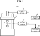
- FIG. 1 is a diagram illustrating a configuration of a stress measurement system according to a first exemplary embodiment.
- Stress measurement system 100 includes vibration generator 10, control device 15, and function generator 40.
- Vibration generator 10 vibrates test piece 1 serving as an example of an object to be measured according to the present disclosure at a predetermined frequency.
- Control device 15 controls a vibration operation of vibration generator 10.
- Function generator 40 outputs a vibration waveform.
- stress measurement system 100 includes infrared camera 30 and information processing device 50 (an example of a stress measurement device according to the present disclosure).
- Infrared camera 30 captures a temperature image (an infrared image) of test piece 1 that has been vibrated.
- Information processing device 50 analyzes the temperature image, and calculates a principal stress sum, a physical property value, or the like of test piece 1.
- An output signal of function generator 40 is input to infrared camera 30 in addition to control device 15.
- Control device 15 controls a vibration frequency of vibration generator 10 on the basis of the output signal from function generator 40. By doing this, a captured image of infrared camera 30 and a vibration frequency applied to test piece 1 are synchronized with each other.
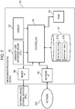
- FIG. 2 is a block diagram explaining an internal configuration of information processing device 50.
- Information processing device 50 is, for example, a personal computer.
- Information processing device 50 includes controller 51 that controls an entire operation of information processing device 50, display 53 that displays information, operation unit 55 that is used for a user to perform an operation, and random access memory (RAM) 56 and data storage 57 that store data or a program.
- controller 51 that controls an entire operation of information processing device 50
- display 53 that displays information
- operation unit 55 that is used for a user to perform an operation
- RAM random access memory
- data storage 57 that store data or a program.
- Information processing device 50 further includes device interface 58 (an example of an obtaining unit according to the present disclosure) for connection to an external device such as infrared camera 30, and network interface 59 (an example of the obtaining unit according to the present disclosure) for connection to a network.
- Device interface 58 is a communication module (a circuit) that communicates data or the like according to universal serial bus (USB), high-definition multimedia interface (HDMI) (registered trademark), IEEE 1394, or the like.
- Network interface 59 is a communication module (a circuit) that performs data communication according to standards such as IEEE 802.11, WiFi, Bluetooth (registered trademark), 3G, 4G, long term evolution (LTE), or the like.
- Controller 51 (an example of an arithmetic unit) includes a central processing unit (CPU) or a micro-processing unit (MPU), and realizes predetermined functions by executing predetermined control program 57a that is stored in data storage 57.
- CPU central processing unit
- MPU micro-processing unit
- Display 53 is, for example, a liquid crystal display or an organic electroluminescence (EL) display.
- EL organic electroluminescence
- RAM 56 is a storage element that transitorily stores a program or data, and functions as a working area of controller 51.
- Data storage 57 is a recording medium that stores a parameter, data, and a program that are needed to realize functions.
- Data storage 57 stores a control program that is executed by controller 51 or various types of data.
- Data storage 57 includes, for example, a hard disk drive (HDD), a solid state drive (SSD), or an optical disc medium.
- Control program 57a is installed in data storage 57.
- Controller 51 realizes the functions described later by executing control program 57a described above.
- Data storage 57 also functions as a working area of controller 51.
- Data storage 57 stores measurement data and reference table 57b that is referred to when fitting is performed on the measurement data.
- Reference table 57b is a table that indicates a probability of obtaining a correct solution for each combination of an angular frequency and respective ranges of coefficients of a one-dimensional heat conduction equation (details are described later).
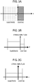
- FIG. 3A is a diagram illustrating a one-dimensional uniaxial tension theoretical analysis model in consideration of only heat conduction in a thickness direction according to the present exemplary embodiment.
- an origin is set on an outer surface of the substrate (an interface between the substrate and the coating), and it is assumed that a load direction is a y-axis, a direction in a substrate surface that is perpendicular to the load direction is an x-axis, and a thickness direction of the substrate is a z-axis.
- Stress measurement using stress measurement system 100 according to the present exemplary embodiment is performed according to the procedure described below.
- Test piece 1 is vibrated at a plurality of vibration frequencies, and a change in a temperature on a surface of an object to be measured during vibration is measured by using infrared camera 30 (obtainment of measurement data).
- a theoretical solution of a temperature amplitude on a surface of a coating film is derived.
- the theoretical solution is obtained from a one-dimensional heat conduction equation in consideration of heat conduction and thermoelastic effects of both a substrate and a coating material.
- the theoretical solution is curve-fitted to frequency characteristics of a temperature change component and a phase component based on the thermoelastic effects, the frequency characteristics being obtained from measurement data obtained due to vibration at the plurality of oscillation frequencies, so that respective variables (coefficients) of the theoretical solution to the one-dimensional heat conduction equation are identified.
- a principal stress sum of the object to be measured is obtained from the respective identified variables.
- a physical property value of the coating material of the object to be measured can also be obtained from the respective identified variables.
- Test piece 1 serving as an object to be measured includes a substrate and a coating film formed on a surface of the substrate.
- Test piece 1 is set in vibration generator 10.
- Control device 15 controls vibration generator 10 on the basis of a vibration signal from function generator 40. Specifically, control device 15 controls vibration generator 10 in such a way that vibration generator 10 repeatedly applies a tensile stress or a compressive stress to test piece 1 at each of a plurality of types of vibration frequencies.
- Infrared camera 30 photographs test piece 1 to which the tensile stress or the compressive stress has been applied at each of the vibration frequencies so as to generate a temperature image.
- Data processing is performed on the temperature image measured by infrared camera 30 in information processing device 50 having a Fourier transform function.
- Information processing device 50 obtains a principal stress sum, a physical property value, and the like of test piece 1 (the substrate) on the basis of the temperature image (an infrared image) captured by infrared camera 30.
- information processing device 50 captures a temperature image from infrared camera 30 in a temporally continuous manner, and information processing device 50 performs Fourier transform on the temperature image in pixel units so as to generate temperature amplitude data and temperature phase data.
- FIG. 4A illustrates an example of the temperature amplitude data obtained as described above.
- FIG. 4B illustrates an example of the temperature phase data (a phase delay).
- the results illustrated in FIGS. 4A and 4B relate to test pieces each including an acrylonitrile butadiene styrene (ABS) resin substrate that has been coated with black paint.
- ABS acrylonitrile butadiene styrene
- No. 1 to No. 3 indicate pieces of data of three types of test pieces in which coating films have thicknesses different from each other.
- Information processing device 50 performs curve-fitting on the temperature amplitude data and the temperature phase data that have been obtained from measurement data, as described above, by using a one-dimensional heat conduction equation so as to obtain respective variables of the one-dimensional heat conduction equation.
- a one-dimensional heat conduction equation to be used in the present exemplary embodiment is described below.
- a one-dimensional heat conduction equation to be used in information processing device 50 according to the present exemplary embodiment is expressed as formula (1) described below.
- temperature T ⁇ theory indicates a value obtained by performing Fourier transform on temperature.
- a theoretical solution of temperature is indicated by an expression (T* theory ) that has been obtained by making temperature T theory dimensionless by using initial temperature T 0 .
- C 1 to C 4 are respectively expressed as the following.
- C 1 c 1 c 4
- C 2 c 3 c 5 2
- an amplitude of a vertical axis has been made dimensionless.
- a horizontal axis indicates a dimensionless angular frequency, and the dimensionless angular frequency is indicated by a logarithmic expression.
- Information processing device 50 performs inverse analysis by using a theoretical solution of a temperature on the coating surface so as to identify a principal stress sum of the substrate from measurement data of a change in the temperature on the coating surface, the measurement data having been obtained by infrared camera 30.
- Information processing device 50 needs to solve a four-dimensional inverse problem using C 1 , C 2 , C 3 , and C 4 in formula (1) as variables in a process of identifying the principal stress sum of the substrate.
- the principal stress sum of the substrate is obtained by substituting an identified value of C 4 in formula (2d).
- identified values of C 2 and C 3 are used, a thermophysical property value and film thickness Lc of a coating can be identified.
- thermophysical property value and the thickness can be obtained from these values.
- inverse analysis can be performed to obtain C 1 , C 2 , C 3 , and C 4 , and a thermophysical property value and a film thickness of a coating material in addition to the principal stress sum of the substrate can be identified from these values.
- the present exemplary embodiment defines an objective function of an inverse problem (a nonlinear least-squares problem) of obtaining C 1 , C 2 , C 3 , and C 4 from measurement data of a temperature on a surface of the coating based on a temperature image captured by infrared camera 30 by using a theoretical solution of the temperature on the surface of the coating.
- an inverse problem a nonlinear least-squares problem
- a temperature on the surface of the coating is measured by using infrared thermography, and data of temperature amplitude (A i ) and phase delay ( ⁇ i ) is obtained.
- the obtained data is converted as described below in order to use a theoretical solution to a one-dimensional heat conduction equation (see formula (1)) for fitting.
- temperature amplitude (A i ) and phase delay ( ⁇ i ) are converted into dimensionless temperature data b* i .
- b i ⁇ A i e j ⁇ i / T 0
- T 0 is an initial temperature of the substrate and the coating material.
- T i ⁇ Cx ⁇ C 4 1 ⁇ C 1 sinh 1 + i ⁇ i ⁇ 2 C 2 C 3 tanh 1 + i ⁇ i ⁇ 2 + 1 tanh 1 + i ⁇ i ⁇ 2 C 2 + C 1
- objective function F is defined as described below as a residual sum of squares of model function T* i and dimensionless temperature data b* i .
- a trust region method can be used in a case where there are no constraints
- a trust region reflective method can be used in a case where there are constraints.
- the "case where there are constraints” refers to a case where a physical property value that configures variables has been measured in advance or a case where a possible range of the physical property value is known. For example, this is because film thickness L c of the coating material can be measured in advance in some cases.
- the "case where there are no constraints” refers to a case where the physical property value that configures the variables fails to be measured in advance or a case where the possible range of the physical property value is not known.
- the inventors of the present application have investigated a relationship between ranges of respective parameters of ⁇ * and C 1 to C 4 and a probability of a value of maximum error e max obtained when inverse analysis is performed using values within these ranges becoming less than or equal to 10%.
- Information indicating this relationship is stored as a reference table in data storage 57 of information processing device 50.
- this reference table indicating the relationship between the ranges of the respective parameters and the probability of the value of maximum error e max becoming less than or equal to 10% is referred to as a "first reference table".
- a first reference table has been prepared for each of a plurality of ranges of ⁇ *.
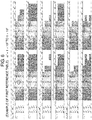
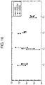
- FIG. 6 is a diagram illustrating an example of a first reference table for a range of ⁇ * of 1 ⁇ 10 2 to 1 ⁇ 10 4 .
- Information processing device 50 also includes a first reference table for another range of ⁇ *, but this is not illustrated.
- a probability of maximum error e max becoming less than 10% is 51%.
- the inventors of the present application have investigated a relationship between ranges of respective parameters of ⁇ * and C 1 to C 4 and a probability of a value of error e 4 relating to C 4 that is obtained when inverse analysis is performed using values within these ranges becoming less than or equal to 10%.
- Information indicating this relationship is stored as a reference table in data storage 57 of information processing device 50.
- this reference table indicating the relationship between the ranges of the respective parameters and the probability of the value of error e 4 relating to C 4 becoming less than or equal to 10% is referred to as a "second reference table".
- a second reference table has been prepared for each of a plurality of ranges of ⁇ *.
- FIG. 7 illustrates an example of the second reference table.
- FIG. 7 is a diagram illustrating an example of a second reference table for a range of ⁇ * of 1 ⁇ 10 -2 to 1 ⁇ 10°.
- Information processing device 50 also includes a second reference table for another range of ⁇ *, but this is not illustrated.
- the principal stress sum in a case where the principal stress sum is calculated, it is sufficient if C 4 can be precisely identified. Therefore, as described below in ⁇ 1-2-1. Method for calculating principal stress sum>, it is sufficient if the "second reference table" is used in processing for calculating the principal stress sum.
- the second reference table has a wider application range of a coating material that enables C 4 to be precisely identified than an application range of the first reference table.
- thermophysical property value of the coating film In a case where a thermophysical property value of the coating film is calculated, C 2 needs to be precisely identified. In addition, in order to calculate a film thickness of the coating film, C 3 needs to be precisely identified. Therefore, as described below in ⁇ 1-2-2.
- Method for calculating thermophysical property value or film thickness of coating film> the "first reference table" needs to be used in processing for calculating the thermophysical property value or the film thickness of the coating film.
- FIG. 8 is a flowchart illustrating processing for calculating a principal stress sum in information processing device 50. The processing for calculating the principal stress sum is described below with reference to this flowchart. This processing is performed by controller 51 of information processing device 50.
- Controller 51 first obtains physical property value ( ⁇ m , c m , k m , ⁇ m , E m , v m ) and thickness (L m ) of a substrate material (step S11).
- a physical property value or the like of the substrate material or the coating material can be given in various data forms. These pieces of data may be input via operation unit 55 by a user, or may be input to information processing device 50 via network 200.
- controller 51 obtains approximate values of physical property value ( ⁇ c , c c , k c , ac, E c , v c ) and thickness (L c ) of the coating material (step S12).
- ⁇ c , c c , k c , ac, E c , v c thickness of the coating material
- ⁇ density
- c p specific heat at constant pressure
- k heat conductivity
- ⁇ linear expansion coefficient
- E a modulus of longitudinal elasticity
- v a Poisson's ratio
- ⁇ B a tensile strength
- As the substrate material two or three representative materials from among metal, ceramics, and polymer materials are illustrated.
- As the coating material values of black paint and polyimide are illustrated.
- a principal component of black paint is silicone resin, and therefore a physical property value of silicone resin is also indicated as a reference value.
- controller 51 selects one table of a plurality of second reference tables (see FIG. 7 ) on the basis of a range of angular frequency ⁇ * (step S14).
- Controller 51 determines whether a probability for a region that corresponds to respective variables C 1 to C 4 in the selected table is greater than or equal to a predetermined value (for example, 70%) (step S15).
- a predetermined value for example, 70%
- the predetermined value is set to, for example, 70%.
- step S15 In a case where a probability for a corresponding region is less than the predetermined value (NO in step S15), a physical property value and a thickness of a coating material are newly set by a user (step S20), and the processing returns to step S13. By doing this, ranges of the respective variables are reset, and a second reference table is selected again.
- controller 51 performs inverse analysis by using formula (7) while changing values of variables C 1 to C 4 within ranges specified in the selected second reference table, and identifies variables C 1 to C 4 (step S16).
- controller 51 calculates principal stress sum ⁇ m on the basis of C 4 by using formula (8a) (step S17). By doing this, principal stress sum ⁇ m is obtained.
- an infrared image includes noise due to infrared camera 30. Therefore, if a value of C 4 obtained in inverse analysis is less than a level of the noise, the value fails to be distinguished from the noise, and the value is considered to be a value having a low reliability. In contrast, if the value of C 4 obtained in inverse analysis is greater than the level of the noise, the value has not received an influence of the noise, and the value is considered to be a value having a high reliability.
- Controller 51 calculates principal stress sum ⁇ m , and also determines whether the value of C 4 is greater than or equal to a predetermined value (for example, 1 ⁇ 10 -4 ) (step S18).
- the predetermined value is set to be greater than or equal to a noise level of infrared camera 30.
- controller 51 determines that obtained values of C 1 to C 4 have not received an influence of noise (step S19).
- controller 51 determines that the obtained values (identified values) of C 1 to C 4 have received an influence of noise (step S21).
- This determination result may be displayed on display 53 of information processing device 50, or may be stored as a flag indicating the determination result in data storage 57 in association with the obtained values.
- principal stress sum ⁇ m of the substrate material of test piece 1 can be obtained on the basis of data of an infrared image of test piece 1.
- thermophysical property value or film thickness of coating film
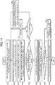
- FIG. 11 is a flowchart illustrating processing for calculating a thermophysical property value or a film thickness of a coating film in information processing device 50.
- the processing for calculating the thermophysical property value or the film thickness of the coating film is described below with reference to this flowchart. This processing is performed by controller 51 of information processing device 50.
- Controller 51 first obtains physical property value ( ⁇ m , c m , k m , a m , E m , v m ) and thickness (L m ) of a substrate material (step S31).
- controller 51 obtains approximate values of physical property value ( ⁇ c , c c , k c , a c , E c , v c ) and thickness (L c ) of the coating material (step S32).
- ⁇ c , c c , k c , a c , E c , v c thickness of the coating material
- Controller 51 calculates possible ranges of angular frequency ⁇ * and variables C 1 to C 4 (step S33).
- controller 51 selects one table of a plurality of first reference tables (see FIG. 6 ) on the basis of a range of angular frequency ⁇ * (step S34).
- Controller 51 determines whether a probability for a region that corresponds to respective variables C 1 to C 4 in the selected first reference table is greater than or equal to a predetermined value (for example, 70%) (step S35).
- a predetermined value for example, 70%
- controller 51 further determines whether a load can be increased (namely, whether C 4 ) can be increased (step S40). In a case where the load (C 4 ) can be increased (YES in step S40), controller 51 increases C 4 (step S41), and the processing returns to step S32. In contrast, in a case where the load (C 4 ) fails to be increased (NO in step S40), controller 51 newly sets the physical property values and the thicknesses of the substrate and the coating material (step S42). Stated another way, a value of C 2 is adjusted, and the processing returns to step S32. By doing this, the ranges of the respective variables are reset, and a first reference table is selected again.
- controller 51 performs inverse analysis by using formula (7) while changing values of respective variables C 1 to C 4 within ranges specified in the selected first reference table, and identifies variables C 1 to C 4 (step S36).
- controller 51 calculates a thermophysical property value or a film thickness of the coating material on the basis of C 2 and C 3 (step S37). Stated another way, if either one of the thermophysical property value and the film thickness of the coating material is known, an unknown value of the thermophysical property value and the film thickness can be obtained by using C 2 , C 3 , and a known value of the thermophysical property value and the film thicknesses.
- controller 51 determines whether a value of C 4 is greater than or equal to a predetermined value (for example, 1 ⁇ 10 -4 ) (step S38).
- the predetermined value is set to be greater than or equal to a noise level of infrared camera 30.
- controller 51 determines that obtained values of C 1 to C 4 have not received an influence of noise (step S39).
- controller 51 determines that the obtained values (identified values) of C 1 to C 4 have received the influence of noise (step S43).
- test piece 1 a physical property value of a coating material of an object to be measured (test piece 1) can be measured in addition to a principal stress sum.
- Test piece 1 that had been coated was attached to a hydraulic servo fatigue testing machine, and a sine wave shape repeated load of uniaxial tension was applied. A change in temperature due to a thermoelastic effect generated on a surface of test piece 1 to which the load had been applied was photographed by using infrared camera 30 (infrared thermography).
- infrared camera 30 infrared thermography
- frequency analysis was performed on data of a captured temperature image so as to obtain an amplitude characteristic and a phase characteristic of a surface temperature.
- vibration generator 10 As vibration generator 10, the hydraulic servo fatigue testing machine "L10kN” from Shimadzu Corporation was used. In addition, as control device 15 of vibration generator 10, the 4830 type from Shimadzu Corporation was used. As infrared camera 30, the infrared thermography “Silver 480M” from Cedip Infrared Systems was used.
- test pieces obtained by coating two types of substrate materials, ABS and SUS304, with black paint, and a test piece obtained by coating an aluminum substrate material with a polyimide tape were used.
- an ABS substrate three types of test pieces for which coating films have thicknesses different from each other were prepared.
- SUS304 substrate five types of test pieces for which coating films have thicknesses different from each other were prepared.
- the aluminum (A5052) substrate material two types of test pieces (A5052-1, A5052-2) for which coating films have thicknesses (55 ⁇ m, 110 ⁇ m) different from each other were prepared.
- a load amplitude (both amplitudes) is 0.1 kN for the ABS substrate, 3.0 kN for the SUS304 substrate, and 3.0 kN for the A5052 substrate.
- Vibration frequency f is 1, 3, 5, 10, 15, 20, 25, or 30 Hz.
- An experiment was also conducted at 35 or 40 Hz only for A5052-2.
- Photographing conditions of infrared camera 30 are described below.
- a frame rate was assumed to be 249 Hz, and 2000-frame photographing was performed at each of the vibration frequencies.
- Fourier transform is performed on data of a change in temperature and a phase that has been obtained by infrared camera 30 in pixel units at the vibration frequency in information processing device 50, so that the data is converted into a temperature amplitude and a temperature phase (a phase delay) at each of the frequencies.
- FIGS. 12A to 14B A fitting curve obtained by performing inverse analysis on measurement data of each of the test pieces is illustrated in FIGS. 12A to 14B .
- FIGS. 12A and 12B respectively illustrate temperature amplitude A [K] and temperature phase (phase delay) ⁇ [rad] with respect to a test piece of the ABS substrate.
- FIGS. 13A and 13B respectively illustrate temperature amplitude A [K] and temperature phase (phase delay) ⁇ [rad] with respect to a test piece of the SUS304 substrate.
- FIGS. 14A and 14B respectively illustrate temperature amplitude A [K] and temperature phase (phase delay) ⁇ [rad] with respect to a test piece of the A5052 substrate.
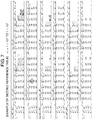
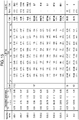
- FIG. 15 Four parameters identified as described above, and a principal stress sum (a stress amplitude) and a film thickness of a coating material that have been calculated from the four parameters are illustrated in FIG. 15 .
- a stress measurement method is a method for measuring a stress of an object to be measured that includes a substrate and a coating film.
- test piece 1 (the object to be measured) is vibrated at a plurality of oscillation frequencies.
- a temperature amplitude of test piece 1 is measured by using infrared camera 30 (a temperature sensor).
- Parameters of a one-dimensional heat conduction equation ((see formulae (1) and (2a) to (2d)))) are identified by performing curve-fitting, on the basis of the one-dimensional heat conduction equation, on a measurement value of the temperature amplitude with respect to frequency characteristics of a temperature change component and a phase component based on a thermoelastic effect.
- the frequency characteristics are obtained at the plurality of oscillation frequencies.
- the one-dimensional heat conduction equation indicates a theoretical solution of a temperature amplitude on a surface of the coating film based on heat conduction and the thermoelastic effect of both the substrate and the coating film. Then, a stress of test piece 1 is obtained on the basis of the identified parameters.
- the curve-fitting includes fitting according to a least-squares method.
- a trust region method or a trust region reflective method is used as the least-squares method.
- a reference table (an example of table information) is stored for a plurality of combinations of the substrate and the coating film.
- the reference table indicates possible ranges of the parameters of the one-dimensional heat conduction equation at oscillation frequencies different from each other.
- the reference table is referred to, the possible ranges of the parameters of the one-dimensional heat conduction equation are set, and curve fitting is performed while the parameters are changed within the set ranges.
- the stress measurement method further includes obtaining a thermophysical property or a film thickness of the coating film on the basis of the identified parameters.
- the present exemplary embodiment also discloses a stress measurement device of an object to be measured that includes a substrate and a coating film.
- the stress measurement device according to the present exemplary embodiment is a stress measurement device that obtains a value of a stress of an object to be measured including a substrate and a coating film on the basis of a temperature amplitude image of the object to be measured that has been vibrated.
- the stress measurement device includes device interface 58 (an example of an obtaining unit) that obtains a temperature amplitude, and controller 51 (an example of a controller) that calculates a stress of test piece 1 (an example of the object to be measured) on the basis of the temperature amplitude image.
- Controller 51 obtains, from the temperature amplitude, a measurement value of a temperature amplitude on a surface of the coating film based on heat conduction and a thermoelastic effect of both the substrate and the coating film, and identifies parameters of a one-dimensional heat conduction equation ((see formulae (1) and (2a) to (2d))) by performing curve-fitting, on the basis of the one-dimensional heat conduction equation, on the measurement value of the temperature amplitude with respect to frequency characteristics of a temperature change component and a phase component based on the thermoelastic effect.
- the frequency characteristics are obtained at a plurality of oscillation frequencies different from each other.
- the one-dimensional heat conduction equation indicates a theoretical solution of the surface of the coating film. Controller 51 obtains the stress of the object to be measured on the basis of the identified parameters.
- the present exemplary embodiment also discloses a stress measurement system of an object to be measured that includes a substrate and a coating film.
- Stress measurement system 100 is a system that vibrates an object to be measured that includes a substrate and a coating film, measures a temperature amplitude of the object to be measured, and obtains a value of a stress of the object to be measured from a measurement result.
- Stress measurement system 100 includes vibration generator 10 that repeatedly applies a load to test piece 1 (an example of the object to be measured) at a predetermined frequency, infrared camera 30 (an example of a temperature sensor) that measures a temperature amplitude of test piece 1 that the load has been applied to, and information processing device 50 (an example of a stress measurement device) that obtains the stress of the object to be measured on the basis of a temperature image that has been obtained from infrared camera 30.
- vibration generator 10 that repeatedly applies a load to test piece 1 (an example of the object to be measured) at a predetermined frequency
- infrared camera 30 an example of a temperature sensor
- information processing device 50 an example of a stress measurement device
- Controller 51 identifies parameters of a one-dimensional heat conduction equation ((see formulae (1) and (2a) to (2d))) by performing curve-fitting, on the basis of the one-dimensional heat conduction equation, on a measurement value of the temperature amplitude with respect to frequency characteristics of a temperature change component and a phase component based on a thermoelastic effect.
- the frequency characteristics are obtained at a plurality of oscillation frequencies.
- the one-dimensional heat conduction equation indicates a theoretical solution of a temperature amplitude on a surface of the coating film based on heat conduction and the thermoelastic effect of both the substrate and the coating film. Controller 51 obtains the stress of the object to be measured on the basis of the identified parameters.
- the first exemplary embodiment has been described as an example of the technique disclosed in the present application.
- the technique of the present disclosure is not limited to the first exemplary embodiment, and is also applicable to exemplary embodiments that have undergone modifications, replacements, additions, omissions, or the like, as appropriate.
- new exemplary embodiments can also be achieved by combining the respective components described in the first exemplary embodiment above.
- the substrate and the coating material of the object to be measured (the test piece) that have been described above are examples, and an idea of the present disclosure is applicable to objects to be measured that respectively include a variety of substrates and coating materials.
- controller 51 may be provided to information processing device 50 via network 200, or may be installed from a recording medium such as a compact disc read-only memory (CD-ROM).
- controller 51 may be a dedicated circuit that has been designed so as to realize a function of controller 51 by only using a hardware circuit.
- Controller 51 may include a CPU or an MPU, or may include a digital signal processor (DSP), a field-programmable gate array (FPGA), an application specific integrated circuit (ASIC), or the like.
- DSP digital signal processor
- FPGA field-programmable gate array
- ASIC application specific integrated circuit
- an infrared camera that is capable of obtaining a temperature image has been used as a temperature sensor.
- a temperature sensor according to the present disclosure is not limited to the infrared camera.
- a contact type or non-contact type temperature sensor may be used, and a stress of an object to be measured may be measured on the basis of a temperature amplitude at a specified point.
- the components described in the accompanying drawings and the detailed description may not only include components that are essential for solving the problems, but may also include components that are not essential for solving the problems. For this reason, it should not be immediately deemed that those components that are not essential are essential just because those components that are not essential are described in the accompanying drawings and the detailed description.
- the present disclosure can be applied to a measurement device that measures a stress of an object to be measured that includes a substrate and a coating film on the basis of an infrared image.
Landscapes
- General Physics & Mathematics (AREA)
- Physics & Mathematics (AREA)
- Chemical & Material Sciences (AREA)
- Analytical Chemistry (AREA)
- Biochemistry (AREA)
- Life Sciences & Earth Sciences (AREA)
- Health & Medical Sciences (AREA)
- General Health & Medical Sciences (AREA)
- Immunology (AREA)
- Pathology (AREA)
- Engineering & Computer Science (AREA)
- Computer Vision & Pattern Recognition (AREA)
- Investigating Or Analyzing Materials Using Thermal Means (AREA)
- Radiation Pyrometers (AREA)
Applications Claiming Priority (2)
| Application Number | Priority Date | Filing Date | Title |
|---|---|---|---|
| JP2017023497A JP6796813B2 (ja) | 2017-02-10 | 2017-02-10 | 応力測定システムおよび応力測定方法 |
| PCT/JP2017/036067 WO2018146857A1 (ja) | 2017-02-10 | 2017-10-04 | 応力の測定方法、応力測定装置および応力測定システム |
Publications (3)
| Publication Number | Publication Date |
|---|---|
| EP3561468A1 true EP3561468A1 (de) | 2019-10-30 |
| EP3561468A4 EP3561468A4 (de) | 2020-01-22 |
| EP3561468B1 EP3561468B1 (de) | 2021-03-24 |
Family
ID=63107377
Family Applications (1)
| Application Number | Title | Priority Date | Filing Date |
|---|---|---|---|
| EP17895936.7A Active EP3561468B1 (de) | 2017-02-10 | 2017-10-04 | Stressmessverfahren, stressmessvorrichtung und stressmesssystem |
Country Status (4)
| Country | Link |
|---|---|
| US (1) | US11467046B2 (de) |
| EP (1) | EP3561468B1 (de) |
| JP (1) | JP6796813B2 (de) |
| WO (1) | WO2018146857A1 (de) |
Cited By (1)
| Publication number | Priority date | Publication date | Assignee | Title |
|---|---|---|---|---|
| EP4036542A1 (de) * | 2021-02-02 | 2022-08-03 | Sumitomo Rubber Industries, Ltd. | Auswertungsverfahren |
Families Citing this family (5)
| Publication number | Priority date | Publication date | Assignee | Title |
|---|---|---|---|---|
| CN110047357A (zh) * | 2019-04-30 | 2019-07-23 | 清华大学 | 双轴载荷应变测试实验教学系统及方法 |
| EP3964812A4 (de) * | 2019-05-30 | 2022-06-29 | Panasonic Intellectual Property Management Co., Ltd. | Vorrichtung zur belastungsanalyse eines beweglichen körpers |
| CN110426279B (zh) * | 2019-07-05 | 2021-04-13 | 大连理工大学 | 一种基于图像测量技术的土样拉伸试验装置及其实施方法 |
| CN114813410B (zh) * | 2022-07-01 | 2022-09-16 | 沈阳美茵联合检测有限公司 | 一种航空液压导管旋转弯曲疲劳s/n曲线拟合试验方法 |
| CN115060582B (zh) * | 2022-08-11 | 2022-11-15 | 四川至臻光电有限公司 | 一种测量薄膜抗拉伸强度的测试方法及测试装置 |
Family Cites Families (10)
| Publication number | Priority date | Publication date | Assignee | Title |
|---|---|---|---|---|
| US7363173B2 (en) * | 2004-06-01 | 2008-04-22 | California Institute Of Technology | Techniques for analyzing non-uniform curvatures and stresses in thin-film structures on substrates with non-local effects |
| JP4578384B2 (ja) * | 2004-10-29 | 2010-11-10 | 株式会社神戸製鋼所 | 赤外線映像装置を用いた応力測定方法および強度評価方法 |
| PL2508906T3 (pl) * | 2011-02-14 | 2017-10-31 | Magcam Nv | Sposób oraz układ do badania układów magnetycznych |
| JP5953801B2 (ja) * | 2011-02-21 | 2016-07-20 | Jfeスチール株式会社 | 鋳片の凝固状態推定装置及び推定方法、連続鋳造装置及び連続鋳造方法、最終凝固予測方法 |
| EP2557584A1 (de) | 2011-08-10 | 2013-02-13 | Fei Company | Mikroskopiebildgebungsverfahren mit geladenen Teilchen |
| US8704176B2 (en) | 2011-08-10 | 2014-04-22 | Fei Company | Charged particle microscope providing depth-resolved imagery |
| JP6153395B2 (ja) * | 2013-06-13 | 2017-06-28 | パナソニック株式会社 | 赤外線応力測定方法、および赤外線応力測定システム |
| JP6354317B2 (ja) * | 2013-09-25 | 2018-07-11 | 株式会社ジェイテクト | 応力計測システム、応力計測方法および応力計測用処理装置 |
| JP6223294B2 (ja) * | 2014-07-22 | 2017-11-01 | パナソニック株式会社 | 赤外線応力測定システムにおける応力値の補正方法およびその方法を用いた赤外線応力測定システム |
| JP6735508B2 (ja) * | 2016-12-26 | 2020-08-05 | パナソニックIpマネジメント株式会社 | 疲労限度応力特定システム及び疲労限度応力特定方法 |
-
2017
- 2017-02-10 JP JP2017023497A patent/JP6796813B2/ja active Active
- 2017-10-04 WO PCT/JP2017/036067 patent/WO2018146857A1/ja not_active Ceased
- 2017-10-04 EP EP17895936.7A patent/EP3561468B1/de active Active
-
2019
- 2019-07-31 US US16/527,582 patent/US11467046B2/en active Active
Cited By (1)
| Publication number | Priority date | Publication date | Assignee | Title |
|---|---|---|---|---|
| EP4036542A1 (de) * | 2021-02-02 | 2022-08-03 | Sumitomo Rubber Industries, Ltd. | Auswertungsverfahren |
Also Published As
| Publication number | Publication date |
|---|---|
| US11467046B2 (en) | 2022-10-11 |
| WO2018146857A1 (ja) | 2018-08-16 |
| JP2018128431A (ja) | 2018-08-16 |
| EP3561468B1 (de) | 2021-03-24 |
| JP6796813B2 (ja) | 2020-12-09 |
| US20190353538A1 (en) | 2019-11-21 |
| EP3561468A4 (de) | 2020-01-22 |
Similar Documents
| Publication | Publication Date | Title |
|---|---|---|
| US11467046B2 (en) | Stress measurement method, stress measurement device, and stress measurement system | |
| Leclère et al. | Practical implementation of the corrected force analysis technique to identify the structural parameter and load distributions | |
| US11275005B2 (en) | Fatigue limit stress specification system, fatigue limit stress specification device, and fatigue limit stress specification method | |
| Baldoni et al. | Comparison of different filtering strategies to reduce noise in strain measurement with digital image correlation | |
| KR102064630B1 (ko) | 위상 특성들을 일치하기 위한 지연을 이용하는 트랜스듀서 가속도 보상 | |
| CN105675186B (zh) | 基于动态光弹性系统的应力测量方法 | |
| JP2018004504A (ja) | 多軸振動制御装置 | |
| Madigosky et al. | A method for modeling polymer viscoelastic data and the temperature shift function | |
| Vuye et al. | Optical measurement of the dynamic strain field of a fan blade using a 3D scanning vibrometer | |
| Xu | An algorithm for selecting the most accurate protocol for contact angle measurement by drop shape analysis | |
| CN104180823B (zh) | 一种温度补偿方法及装置 | |
| JP7122670B2 (ja) | 疲労限度応力特定システム、疲労限度応力特定装置及び疲労限度応力特定方法 | |
| CN111797483A (zh) | 马达均衡电信号的修正方法及设备、计算机可读存储介质 | |
| JP6153395B2 (ja) | 赤外線応力測定方法、および赤外線応力測定システム | |
| Graham et al. | Characterising the frequency‐response of ultra‐soft polymers with the Virtual Fields Method | |
| JP6223294B2 (ja) | 赤外線応力測定システムにおける応力値の補正方法およびその方法を用いた赤外線応力測定システム | |
| JP5852935B2 (ja) | 伝達関数推定装置、伝達関数推定方法、および、伝達関数推定プログラム | |
| JPWO2016147426A1 (ja) | 交流信号解析装置、交流信号解析方法及びプログラム | |
| Veldman | Accelerometer transverse sensitivity calibration; validation and uncertainty estimation | |
| JP7395426B2 (ja) | 疲労限度特定装置および疲労限度特定方法 | |
| KR102088622B1 (ko) | Adc의 주파수 오차 저장 장치 및 adc의 주파수 오차 보정 장치 | |
| JP2011059105A (ja) | 破断特性推定方法及び破断特性推定装置 | |
| Ma et al. | Research on disturbance characteristics in high temperature DIC measurement due to heat flow and its correction method | |
| JP6457408B2 (ja) | イメージング方法 | |
| Veldman | Accelerometer Transverse Sensitivity Calibration at the NMISA |
Legal Events
| Date | Code | Title | Description |
|---|---|---|---|
| STAA | Information on the status of an ep patent application or granted ep patent |
Free format text: STATUS: THE INTERNATIONAL PUBLICATION HAS BEEN MADE |
|
| PUAI | Public reference made under article 153(3) epc to a published international application that has entered the european phase |
Free format text: ORIGINAL CODE: 0009012 |
|
| STAA | Information on the status of an ep patent application or granted ep patent |
Free format text: STATUS: REQUEST FOR EXAMINATION WAS MADE |
|
| 17P | Request for examination filed |
Effective date: 20190723 |
|
| AK | Designated contracting states |
Kind code of ref document: A1 Designated state(s): AL AT BE BG CH CY CZ DE DK EE ES FI FR GB GR HR HU IE IS IT LI LT LU LV MC MK MT NL NO PL PT RO RS SE SI SK SM TR |
|
| AX | Request for extension of the european patent |
Extension state: BA ME |
|
| A4 | Supplementary search report drawn up and despatched |
Effective date: 20200102 |
|
| RIC1 | Information provided on ipc code assigned before grant |
Ipc: G01N 3/34 20060101ALI20191217BHEP Ipc: G01L 1/00 20060101AFI20191217BHEP Ipc: G01L 1/24 20060101ALI20191217BHEP |
|
| DAV | Request for validation of the european patent (deleted) | ||
| DAX | Request for extension of the european patent (deleted) | ||
| RIC1 | Information provided on ipc code assigned before grant |
Ipc: G01N 3/06 20060101ALI20200907BHEP Ipc: G01N 3/08 20060101ALI20200907BHEP Ipc: G01L 1/24 20060101ALI20200907BHEP Ipc: G01L 1/00 20060101AFI20200907BHEP Ipc: G01N 3/34 20060101ALI20200907BHEP Ipc: G01N 3/32 20060101ALI20200907BHEP |
|
| GRAP | Despatch of communication of intention to grant a patent |
Free format text: ORIGINAL CODE: EPIDOSNIGR1 |
|
| STAA | Information on the status of an ep patent application or granted ep patent |
Free format text: STATUS: GRANT OF PATENT IS INTENDED |
|
| INTG | Intention to grant announced |
Effective date: 20201020 |
|
| GRAS | Grant fee paid |
Free format text: ORIGINAL CODE: EPIDOSNIGR3 |
|
| GRAA | (expected) grant |
Free format text: ORIGINAL CODE: 0009210 |
|
| STAA | Information on the status of an ep patent application or granted ep patent |
Free format text: STATUS: THE PATENT HAS BEEN GRANTED |
|
| AK | Designated contracting states |
Kind code of ref document: B1 Designated state(s): AL AT BE BG CH CY CZ DE DK EE ES FI FR GB GR HR HU IE IS IT LI LT LU LV MC MK MT NL NO PL PT RO RS SE SI SK SM TR |
|
| REG | Reference to a national code |
Ref country code: GB Ref legal event code: FG4D |
|
| REG | Reference to a national code |
Ref country code: CH Ref legal event code: EP |
|
| REG | Reference to a national code |
Ref country code: IE Ref legal event code: FG4D |
|
| REG | Reference to a national code |
Ref country code: AT Ref legal event code: REF Ref document number: 1374975 Country of ref document: AT Kind code of ref document: T Effective date: 20210415 Ref country code: DE Ref legal event code: R096 Ref document number: 602017035476 Country of ref document: DE |
|
| REG | Reference to a national code |
Ref country code: LT Ref legal event code: MG9D |
|
| PG25 | Lapsed in a contracting state [announced via postgrant information from national office to epo] |
Ref country code: NO Free format text: LAPSE BECAUSE OF FAILURE TO SUBMIT A TRANSLATION OF THE DESCRIPTION OR TO PAY THE FEE WITHIN THE PRESCRIBED TIME-LIMIT Effective date: 20210624 Ref country code: HR Free format text: LAPSE BECAUSE OF FAILURE TO SUBMIT A TRANSLATION OF THE DESCRIPTION OR TO PAY THE FEE WITHIN THE PRESCRIBED TIME-LIMIT Effective date: 20210324 Ref country code: GR Free format text: LAPSE BECAUSE OF FAILURE TO SUBMIT A TRANSLATION OF THE DESCRIPTION OR TO PAY THE FEE WITHIN THE PRESCRIBED TIME-LIMIT Effective date: 20210625 Ref country code: FI Free format text: LAPSE BECAUSE OF FAILURE TO SUBMIT A TRANSLATION OF THE DESCRIPTION OR TO PAY THE FEE WITHIN THE PRESCRIBED TIME-LIMIT Effective date: 20210324 Ref country code: BG Free format text: LAPSE BECAUSE OF FAILURE TO SUBMIT A TRANSLATION OF THE DESCRIPTION OR TO PAY THE FEE WITHIN THE PRESCRIBED TIME-LIMIT Effective date: 20210624 |
|
| PG25 | Lapsed in a contracting state [announced via postgrant information from national office to epo] |
Ref country code: SE Free format text: LAPSE BECAUSE OF FAILURE TO SUBMIT A TRANSLATION OF THE DESCRIPTION OR TO PAY THE FEE WITHIN THE PRESCRIBED TIME-LIMIT Effective date: 20210324 Ref country code: RS Free format text: LAPSE BECAUSE OF FAILURE TO SUBMIT A TRANSLATION OF THE DESCRIPTION OR TO PAY THE FEE WITHIN THE PRESCRIBED TIME-LIMIT Effective date: 20210324 Ref country code: LV Free format text: LAPSE BECAUSE OF FAILURE TO SUBMIT A TRANSLATION OF THE DESCRIPTION OR TO PAY THE FEE WITHIN THE PRESCRIBED TIME-LIMIT Effective date: 20210324 |
|
| REG | Reference to a national code |
Ref country code: NL Ref legal event code: MP Effective date: 20210324 |
|
| REG | Reference to a national code |
Ref country code: AT Ref legal event code: MK05 Ref document number: 1374975 Country of ref document: AT Kind code of ref document: T Effective date: 20210324 |
|
| PG25 | Lapsed in a contracting state [announced via postgrant information from national office to epo] |
Ref country code: NL Free format text: LAPSE BECAUSE OF FAILURE TO SUBMIT A TRANSLATION OF THE DESCRIPTION OR TO PAY THE FEE WITHIN THE PRESCRIBED TIME-LIMIT Effective date: 20210324 |
|
| PG25 | Lapsed in a contracting state [announced via postgrant information from national office to epo] |
Ref country code: AT Free format text: LAPSE BECAUSE OF FAILURE TO SUBMIT A TRANSLATION OF THE DESCRIPTION OR TO PAY THE FEE WITHIN THE PRESCRIBED TIME-LIMIT Effective date: 20210324 Ref country code: SM Free format text: LAPSE BECAUSE OF FAILURE TO SUBMIT A TRANSLATION OF THE DESCRIPTION OR TO PAY THE FEE WITHIN THE PRESCRIBED TIME-LIMIT Effective date: 20210324 Ref country code: LT Free format text: LAPSE BECAUSE OF FAILURE TO SUBMIT A TRANSLATION OF THE DESCRIPTION OR TO PAY THE FEE WITHIN THE PRESCRIBED TIME-LIMIT Effective date: 20210324 Ref country code: CZ Free format text: LAPSE BECAUSE OF FAILURE TO SUBMIT A TRANSLATION OF THE DESCRIPTION OR TO PAY THE FEE WITHIN THE PRESCRIBED TIME-LIMIT Effective date: 20210324 Ref country code: EE Free format text: LAPSE BECAUSE OF FAILURE TO SUBMIT A TRANSLATION OF THE DESCRIPTION OR TO PAY THE FEE WITHIN THE PRESCRIBED TIME-LIMIT Effective date: 20210324 |
|
| PG25 | Lapsed in a contracting state [announced via postgrant information from national office to epo] |
Ref country code: IS Free format text: LAPSE BECAUSE OF FAILURE TO SUBMIT A TRANSLATION OF THE DESCRIPTION OR TO PAY THE FEE WITHIN THE PRESCRIBED TIME-LIMIT Effective date: 20210724 Ref country code: PT Free format text: LAPSE BECAUSE OF FAILURE TO SUBMIT A TRANSLATION OF THE DESCRIPTION OR TO PAY THE FEE WITHIN THE PRESCRIBED TIME-LIMIT Effective date: 20210726 Ref country code: PL Free format text: LAPSE BECAUSE OF FAILURE TO SUBMIT A TRANSLATION OF THE DESCRIPTION OR TO PAY THE FEE WITHIN THE PRESCRIBED TIME-LIMIT Effective date: 20210324 Ref country code: SK Free format text: LAPSE BECAUSE OF FAILURE TO SUBMIT A TRANSLATION OF THE DESCRIPTION OR TO PAY THE FEE WITHIN THE PRESCRIBED TIME-LIMIT Effective date: 20210324 Ref country code: RO Free format text: LAPSE BECAUSE OF FAILURE TO SUBMIT A TRANSLATION OF THE DESCRIPTION OR TO PAY THE FEE WITHIN THE PRESCRIBED TIME-LIMIT Effective date: 20210324 |
|
| REG | Reference to a national code |
Ref country code: DE Ref legal event code: R097 Ref document number: 602017035476 Country of ref document: DE |
|
| PG25 | Lapsed in a contracting state [announced via postgrant information from national office to epo] |
Ref country code: ES Free format text: LAPSE BECAUSE OF FAILURE TO SUBMIT A TRANSLATION OF THE DESCRIPTION OR TO PAY THE FEE WITHIN THE PRESCRIBED TIME-LIMIT Effective date: 20210324 Ref country code: DK Free format text: LAPSE BECAUSE OF FAILURE TO SUBMIT A TRANSLATION OF THE DESCRIPTION OR TO PAY THE FEE WITHIN THE PRESCRIBED TIME-LIMIT Effective date: 20210324 Ref country code: AL Free format text: LAPSE BECAUSE OF FAILURE TO SUBMIT A TRANSLATION OF THE DESCRIPTION OR TO PAY THE FEE WITHIN THE PRESCRIBED TIME-LIMIT Effective date: 20210324 |
|
| PLBE | No opposition filed within time limit |
Free format text: ORIGINAL CODE: 0009261 |
|
| STAA | Information on the status of an ep patent application or granted ep patent |
Free format text: STATUS: NO OPPOSITION FILED WITHIN TIME LIMIT |
|
| PG25 | Lapsed in a contracting state [announced via postgrant information from national office to epo] |
Ref country code: SI Free format text: LAPSE BECAUSE OF FAILURE TO SUBMIT A TRANSLATION OF THE DESCRIPTION OR TO PAY THE FEE WITHIN THE PRESCRIBED TIME-LIMIT Effective date: 20210324 |
|
| 26N | No opposition filed |
Effective date: 20220104 |
|
| REG | Reference to a national code |
Ref country code: CH Ref legal event code: PL |
|
| PG25 | Lapsed in a contracting state [announced via postgrant information from national office to epo] |
Ref country code: IS Free format text: LAPSE BECAUSE OF FAILURE TO SUBMIT A TRANSLATION OF THE DESCRIPTION OR TO PAY THE FEE WITHIN THE PRESCRIBED TIME-LIMIT Effective date: 20210724 |
|
| REG | Reference to a national code |
Ref country code: BE Ref legal event code: MM Effective date: 20211031 |
|
| PG25 | Lapsed in a contracting state [announced via postgrant information from national office to epo] |
Ref country code: MC Free format text: LAPSE BECAUSE OF FAILURE TO SUBMIT A TRANSLATION OF THE DESCRIPTION OR TO PAY THE FEE WITHIN THE PRESCRIBED TIME-LIMIT Effective date: 20210324 |
|
| PG25 | Lapsed in a contracting state [announced via postgrant information from national office to epo] |
Ref country code: LU Free format text: LAPSE BECAUSE OF NON-PAYMENT OF DUE FEES Effective date: 20211004 Ref country code: BE Free format text: LAPSE BECAUSE OF NON-PAYMENT OF DUE FEES Effective date: 20211031 |
|
| PG25 | Lapsed in a contracting state [announced via postgrant information from national office to epo] |
Ref country code: LI Free format text: LAPSE BECAUSE OF NON-PAYMENT OF DUE FEES Effective date: 20211031 Ref country code: CH Free format text: LAPSE BECAUSE OF NON-PAYMENT OF DUE FEES Effective date: 20211031 |
|
| PG25 | Lapsed in a contracting state [announced via postgrant information from national office to epo] |
Ref country code: IE Free format text: LAPSE BECAUSE OF NON-PAYMENT OF DUE FEES Effective date: 20211004 |
|
| PG25 | Lapsed in a contracting state [announced via postgrant information from national office to epo] |
Ref country code: IT Free format text: LAPSE BECAUSE OF FAILURE TO SUBMIT A TRANSLATION OF THE DESCRIPTION OR TO PAY THE FEE WITHIN THE PRESCRIBED TIME-LIMIT Effective date: 20210324 |
|
| PG25 | Lapsed in a contracting state [announced via postgrant information from national office to epo] |
Ref country code: CY Free format text: LAPSE BECAUSE OF FAILURE TO SUBMIT A TRANSLATION OF THE DESCRIPTION OR TO PAY THE FEE WITHIN THE PRESCRIBED TIME-LIMIT Effective date: 20210324 |
|
| PG25 | Lapsed in a contracting state [announced via postgrant information from national office to epo] |
Ref country code: HU Free format text: LAPSE BECAUSE OF FAILURE TO SUBMIT A TRANSLATION OF THE DESCRIPTION OR TO PAY THE FEE WITHIN THE PRESCRIBED TIME-LIMIT; INVALID AB INITIO Effective date: 20171004 |
|
| PG25 | Lapsed in a contracting state [announced via postgrant information from national office to epo] |
Ref country code: MK Free format text: LAPSE BECAUSE OF FAILURE TO SUBMIT A TRANSLATION OF THE DESCRIPTION OR TO PAY THE FEE WITHIN THE PRESCRIBED TIME-LIMIT Effective date: 20210324 |
|
| PG25 | Lapsed in a contracting state [announced via postgrant information from national office to epo] |
Ref country code: TR Free format text: LAPSE BECAUSE OF FAILURE TO SUBMIT A TRANSLATION OF THE DESCRIPTION OR TO PAY THE FEE WITHIN THE PRESCRIBED TIME-LIMIT Effective date: 20210324 |
|
| PG25 | Lapsed in a contracting state [announced via postgrant information from national office to epo] |
Ref country code: MT Free format text: LAPSE BECAUSE OF FAILURE TO SUBMIT A TRANSLATION OF THE DESCRIPTION OR TO PAY THE FEE WITHIN THE PRESCRIBED TIME-LIMIT Effective date: 20210324 |
|
| PGFP | Annual fee paid to national office [announced via postgrant information from national office to epo] |
Ref country code: DE Payment date: 20251021 Year of fee payment: 9 |
|
| PGFP | Annual fee paid to national office [announced via postgrant information from national office to epo] |
Ref country code: GB Payment date: 20251022 Year of fee payment: 9 |
|
| PGFP | Annual fee paid to national office [announced via postgrant information from national office to epo] |
Ref country code: FR Payment date: 20251030 Year of fee payment: 9 |