EP3561473A1 - Structure composite avec fonction de localisation de dommages et procédé de fabrication d'une structure composite avec fonction de localisation de dommages - Google Patents
Structure composite avec fonction de localisation de dommages et procédé de fabrication d'une structure composite avec fonction de localisation de dommages Download PDFInfo
- Publication number
- EP3561473A1 EP3561473A1 EP18382280.8A EP18382280A EP3561473A1 EP 3561473 A1 EP3561473 A1 EP 3561473A1 EP 18382280 A EP18382280 A EP 18382280A EP 3561473 A1 EP3561473 A1 EP 3561473A1
- Authority
- EP
- European Patent Office
- Prior art keywords
- damage
- optical fiber
- composite part
- fiber sensor
- composite
- Prior art date
- Legal status (The legal status is an assumption and is not a legal conclusion. Google has not performed a legal analysis and makes no representation as to the accuracy of the status listed.)
- Withdrawn
Links
- 239000002131 composite material Substances 0.000 title claims abstract description 135
- 238000000034 method Methods 0.000 title claims abstract description 18
- 238000004519 manufacturing process Methods 0.000 title claims abstract description 16
- 239000013307 optical fiber Substances 0.000 claims abstract description 71
- 238000012545 processing Methods 0.000 claims abstract description 20
- 230000003287 optical effect Effects 0.000 claims abstract description 13
- 238000006073 displacement reaction Methods 0.000 claims abstract description 6
- 230000007704 transition Effects 0.000 claims description 20
- 239000000853 adhesive Substances 0.000 claims description 7
- 230000001070 adhesive effect Effects 0.000 claims description 7
- 238000004891 communication Methods 0.000 claims description 4
- 238000007689 inspection Methods 0.000 description 13
- 230000007547 defect Effects 0.000 description 8
- 239000000835 fiber Substances 0.000 description 4
- 238000001514 detection method Methods 0.000 description 3
- 238000005259 measurement Methods 0.000 description 3
- 238000012544 monitoring process Methods 0.000 description 3
- 230000006978 adaptation Effects 0.000 description 1
- 238000010924 continuous production Methods 0.000 description 1
- 230000032798 delamination Effects 0.000 description 1
- 230000001066 destructive effect Effects 0.000 description 1
- 238000005516 engineering process Methods 0.000 description 1
- 230000005284 excitation Effects 0.000 description 1
- 230000009474 immediate action Effects 0.000 description 1
- 239000000463 material Substances 0.000 description 1
- 238000006116 polymerization reaction Methods 0.000 description 1
- 239000002520 smart material Substances 0.000 description 1
- 230000001960 triggered effect Effects 0.000 description 1
- 238000009966 trimming Methods 0.000 description 1
- 238000002604 ultrasonography Methods 0.000 description 1
Images













Classifications
-
- G—PHYSICS
- G01—MEASURING; TESTING
- G01M—TESTING STATIC OR DYNAMIC BALANCE OF MACHINES OR STRUCTURES; TESTING OF STRUCTURES OR APPARATUS, NOT OTHERWISE PROVIDED FOR
- G01M11/00—Testing of optical apparatus; Testing structures by optical methods not otherwise provided for
- G01M11/08—Testing mechanical properties
- G01M11/083—Testing mechanical properties by using an optical fiber in contact with the device under test [DUT]
- G01M11/086—Details about the embedment of the optical fiber within the DUT
-
- G—PHYSICS
- G01—MEASURING; TESTING
- G01M—TESTING STATIC OR DYNAMIC BALANCE OF MACHINES OR STRUCTURES; TESTING OF STRUCTURES OR APPARATUS, NOT OTHERWISE PROVIDED FOR
- G01M5/00—Investigating the elasticity of structures, e.g. deflection of bridges or air-craft wings
- G01M5/0033—Investigating the elasticity of structures, e.g. deflection of bridges or air-craft wings by determining damage, crack or wear
-
- G—PHYSICS
- G01—MEASURING; TESTING
- G01M—TESTING STATIC OR DYNAMIC BALANCE OF MACHINES OR STRUCTURES; TESTING OF STRUCTURES OR APPARATUS, NOT OTHERWISE PROVIDED FOR
- G01M5/00—Investigating the elasticity of structures, e.g. deflection of bridges or air-craft wings
- G01M5/0016—Investigating the elasticity of structures, e.g. deflection of bridges or air-craft wings of aircraft wings or blades
Definitions
- the present invention refers to a composite structure adapted to identify and localize a damage, such as a disbond or delamination occurred in a composite part.
- One object of the present invention is to provide a composite structure capable of performing an immediate detection and an accurate location of a damage present in a composite part. It is also an object of the invention to characterize the detected damage in order to be able of performing a diagnostic of the damage.
- Another object of the invention is to provide a composite structure capable of lowering the downtime caused by the current inspection of composite parts, and minimizing the need of such inspections, which usually involve unwanted costs and workload.
- the invention also refers to a method for manufacturing a composite structure with damage location capability.
- Another object of the invention is to provide a composite structure that is compatible with the manufacturing conditions of composite parts to easy the adaptations required in these composite parts.
- NDI Non Destructive Inspections
- optical fiber sensors are increasingly advancing with regard to other conventional instruments, becoming one of the best solution for some applications.
- the present invention overcomes the above mentioned drawbacks by providing a composite structure with damage location capability, and a method for manufacturing a composite structure with damage location capability, which reduces the costs and disturbances derived by damaged structures.
- One aspect of the present invention refers to a composite structure with damage location capability that comprises at least one composite part having an area to be monitored, at least one optical fiber sensor in contact with at least the area to be monitored and deployed following a direction, and a processing data unit in communication with the at least one optical fiber sensor.
- the processing data unit is adapted to:
- Equipping a composite part with an optical fiber sensor and a processing data unit configured as mentioned above, provides a permanent damage inspection in said composite part.
- This on-board inspection allows an immediate detection of damage, avoiding the appearance of unexpected damages, and thus the downtime, workload and costs caused by the scheduled and unscheduled inspection of composite parts.
- the invention provides precise location of the detected damages. This way, the invention offers valuable information for the diagnostic of the damage and for the repairing tasks.
- the processing data unit may be further adapted to obtain the size of the identified damage from the value of the distance that each peak of the strain signal has been displaced with respect to the location of said peak in a reference signal associated to the target area in an undamaged composite part.
- processing data unit may be further adapted to obtain the residual strength of the composite part from the size of the identified damage.
- the composite structure is adapted to shape or characterize the detected damage.
- the invention offers valuable information to make a diagnostic of the damage to know how severe is, and if so, if an immediate action to restore load capacity is required.
- the target area may comprise a transition area in the at least one composite part. Transition areas have different thickness and/or stiffness properties with respect to their adjacent areas. Usually, these different properties are caused by structural discontinuities in the composite part. Other target areas may include glued joints and/or structural damages (possibly caused by impacts received during the service of an aircraft).
- the optical fiber sensor consists of multiplexed Bragg gratings or distributed sensing fiber based on the monitoring of the backscattering reflection.
- the invention contemplates an aircraft that comprises a composite structure with damage location capability as describe above.
- the damage detection can be performed off-line, when the aircraft is on ground, and on-line, in a continuous process during flight operation, in function of the configuration of the used processing data unit.
- Another aspect of the invention refers to a method for manufacturing a composite structure with damage location capability comprising the steps of providing at least one composite part having an area to be monitored, providing at least one optical fiber sensor and deploying it following a direction to be in contact with at least the area to be monitored, and providing a processing data unit, in communication with the at least one optical fiber sensor, and configuring the processing data unit to:
- the method of the invention provides a composite structure equipped with a processing data unit and at least one optical fiber sensor in contact with a composite part to provide information (optical information) from which a strain profile can be obtained.
- the method can be applied and used with independence of the curing composite process: co-cured, co-bonded or secondary bonded.
- the method of the invention is compatible with the conventional manufacture of composites, sharing manufacturing conditions, trimming process and final assembly line.
- the method of the invention provides a simple and cost-effective way of producing composite structures with damage location.
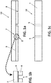
- Figures 1a-c shows different views of an undamaged composite part (10) that includes an upper layout (7), a lower layout (8), and an adhesive line (9) in between bonding the two layers (7, 8) together.
- the undamaged composite part (10) further includes two target areas (5) comprising transition areas. Transition areas have different thickness and/or stiffness properties caused by the inclusion of structural discontinuities with respect to their adjacent areas. Examples of transition areas are areas containing stringer run-outs. In the showed case, the transition areas correspond to a pair of grooves performed in the lower layout (8).
- FIG. 2a-b shows a composite structure (1) according to an embodiment of the invention.
- the structure (1) comprises a composite part (2), an optical fiber sensor (3) to obtain measurements, and a processing data unit (4) connected to the optical fiber sensor (3) for processing said measurements.
- the part (2) has the same configuration and transitions as the part shown in Figure 1 , besides to one (artificial) damage (6) to be detected.
- the optical fiber sensor (3) is embedded into the adhesive line (9) disposed between the layers (7, 8), and deployed along the longitudinal direction of the part (2). Further, as shown in Figure 2b , the optical fiber sensor (3) covers its width to provide more measurements in the transition areas.
- the optical fiber sensor (3) is connected to the processing data unit (4), which, according to the invention, is adapted to obtain optical parameters; convert these optical parameters into strain parameters in an axial (parallel) direction to the direction followed by the optical fiber sensor (3) (major direction of the part (2)), wherein said axial strain parameters represents the mechanical strain magnitude experienced by the composite part (2) along an axial direction to the direction followed by the optical fiber sensor (3) when a force transverse to the direction followed by the optical fiber sensor (3) is applied; form a strain signal (S) from the axial strain parameters; identify one target area (5) (transition area) in the composite part (2) from each peak (Pi) of the strain signal (S) that surpasses a first established value with respect to a reference signal associated to an undamaged composite part, identify a damage (6) in the target area (5) (transition area) from each displacement of each peak (Pi) of the strain signal (S) that surpasses a second established value with respect to a reference signal associated to the undamaged composite part (10), and obtain the location of the
- Figure 3a shows a top view of the composite structure (1) shown in Figure 2 , where different sections (A-B, C-D, E-F) of the optical fiber sensor (3) and the location of the transitions (both extremes of the artificial defect (d1, d2), and groove (d3)) have been marked.
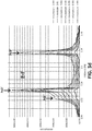
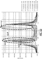
- Figure 3b , 3c , and 3d shows the strain signals obtained from each section (A-B, C-D, E-F) of the optical fiber sensor (3) when different levels of loads (1KN to 7 KN) are transversely applied to the direction followed by the optical fiber sensor (3).
- each section (A-B, C-D, E-F) of the optical fiber sensor (3) detects one transition (Pd1, Pd2; Pd1', Pd2'; Pd1", Pd2") in each one of the both extremes of the artificial defect (6), and a third transition (Pd3; Pd3'; Pd3") corresponding to the second groove.
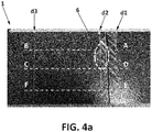
- Figure 4a shows a top view of the composite structure (1) similar to the view shown in Figure 3a in which the detected damage (6) has also been marked.
- one damage specifically a disbond, is detected when a load of 8KN is transversely applied to the composite part (2).
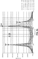
- Figure 4b shows the strain signals obtained from the section A-B of the optical fiber sensor (3) when different levels of loads (1KN to 8 KN) are transversely applied to the direction followed by the optical fiber sensor (3).
- the peak (Pd2) is shifted from the reference signal (consisting of the strain signal obtained when no load or a low load is transversely applied to the composite part (2)), which indicates that a damage (6) has been identified close to d2.
- Figures 4c and 4d show that although increasing levels of loads are applied to the composite part (2), no damage is detected, since no peak (Pd1', Pd2', Pd3'; Pd1", Pd2", Pd3") of the strain signals is displaced with respect to their reference signals.
- Figure 5a shows a top view of the composite structure (1) similar to the view shown in Figure 4a in which the detected damage (6) has grown when a load of 8,5KN has been transversely applied to the composite part (2).
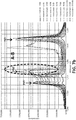
- Figure 5b , 5c and 5d show the strain signals obtained from each of the sections A-B, C-D, E-F of the optical fiber sensor (3) when different levels of loads (1KN to 8,5 KN) are transversely applied to the direction followed by the optical fiber sensor (3).
- the peaks Pd2, Pd2' and Pd2" are shifted from their respective reference signals. This indicates that a damage (6) has been identified close to d2 and in the three sections, i.e. extending along the width of the part (2) as marked in Figure 5a .
- Figure 6a shows a top view of the composite structure (1) similar to the view shown in Figure 5a in which the first detected damage (6) has grown close to the section E-F and a new second damage (6) has appeared when a load of 9KN has been transversely applied to the composite part (2).
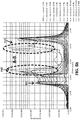
- Figures 6b and 6c show similar strain signals as obtained when a load of 8,5 KN is transversely applied to the direction followed by the optical fiber sensor (3). However, the peak Pd2" is shifted to a greater extent from its reference signal. This indicates that the first damage (6) has just grown in the section E-F.
- Figures 6b , 6c and 6d show that peaks Pd3, Pd3' and Pd3" are shifted from their respective reference signals. This indicates that a new damage (6) has been identified close to d3 and extending along the entire width of the part (2) as marked in Figure 6a .
- Figure 7a shows a top view of the composite structure (1) similar to the view shown in Figure 6a in which the first detected damage (6) has grown towards the second detected damage (6) when a load of 9,5KN has been transversely applied to the composite part (2).
- Figures 7b , 7c and 7d show that peaks Pd2, Pd2' and Pd2" are shifted to a greater extent from their respective reference signals, and towards the direction of d3, as marked in Figure 7a .
- Figure 8a shows a top view of the composite structure (1) similar to the view shown in Figure 7a in which both the first detected damage (6) has grown towards the second detected damage (6), and the second detected damage (6) has grown towards the first detected damage (6), when a load of 10KN has been transversely applied to the composite part (2).
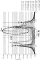
- Figures 8b , 8c and 8d show that peaks Pd2, Pd2' and Pd2" are shifted even to a greater extent from their respective reference signals, and towards the direction of d3, as marked in Figure 8a .
- Figures 8b and 8d show that peaks Pd3 and Pd3" are shifted to a greater extent from their respective reference signals, and towards the direction of d2, as marked in Figure 8a .
- the optical fiber sensor (3) is embedded in the adhesive line (6).
- the optical fiber sensor (3) can be bonded to a surface of the composite part (2) or embedded between the layers of the composite part (2).
- Axial strain parameters can be represented by different types of graphs.
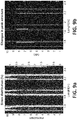
- Figure 9a and 9b shows a color-based graph related to the index of damage, where dark color means high probability of damage, medium dark color that the damage is not yet reached but it is closer (because of a high level of strain), and light color that no damage is foreseen.
- Figure 9a represents the deviation percentage of each peak of each strain signals obtained for the different levels of transversely applied loads (1KN to 10 KN) in the composite structure (1) shown in Figures 2-8 .
- Figure 9b represents the peak deviation values (in mm) of each one of the strain signals obtained for the different levels of transversely applied loads (1KN to 10 KN) in the composite structure (1) shown in Figures 2-8 .
- Figure 10-13 shows the strain signal of a damaged composite part (drawing A), and the reference signal associated to the same composite part when it is undamaged (drawing B), when different levels of force of 4 KN, 5KN, 6KN, and 7KN is transversely applied to said part.
Landscapes
- Physics & Mathematics (AREA)
- General Physics & Mathematics (AREA)
- Engineering & Computer Science (AREA)
- Aviation & Aerospace Engineering (AREA)
- Chemical & Material Sciences (AREA)
- Analytical Chemistry (AREA)
- Length Measuring Devices By Optical Means (AREA)
- Optical Transform (AREA)
Priority Applications (1)
| Application Number | Priority Date | Filing Date | Title |
|---|---|---|---|
| EP18382280.8A EP3561473A1 (fr) | 2018-04-25 | 2018-04-25 | Structure composite avec fonction de localisation de dommages et procédé de fabrication d'une structure composite avec fonction de localisation de dommages |
Applications Claiming Priority (1)
| Application Number | Priority Date | Filing Date | Title |
|---|---|---|---|
| EP18382280.8A EP3561473A1 (fr) | 2018-04-25 | 2018-04-25 | Structure composite avec fonction de localisation de dommages et procédé de fabrication d'une structure composite avec fonction de localisation de dommages |
Publications (1)
| Publication Number | Publication Date |
|---|---|
| EP3561473A1 true EP3561473A1 (fr) | 2019-10-30 |
Family
ID=62222537
Family Applications (1)
| Application Number | Title | Priority Date | Filing Date |
|---|---|---|---|
| EP18382280.8A Withdrawn EP3561473A1 (fr) | 2018-04-25 | 2018-04-25 | Structure composite avec fonction de localisation de dommages et procédé de fabrication d'une structure composite avec fonction de localisation de dommages |
Country Status (1)
| Country | Link |
|---|---|
| EP (1) | EP3561473A1 (fr) |
Cited By (1)
| Publication number | Priority date | Publication date | Assignee | Title |
|---|---|---|---|---|
| CN113740425A (zh) * | 2021-07-12 | 2021-12-03 | 北京航空航天大学 | 一种复合材料层合结构各向异性损伤辨识方法 |
Citations (4)
| Publication number | Priority date | Publication date | Assignee | Title |
|---|---|---|---|---|
| EP1258760A2 (fr) * | 2001-05-15 | 2002-11-20 | The Boeing Company | Connecteur à fibre optique encastrable et son procédé de fabrication |
| US20130268471A1 (en) * | 2012-04-06 | 2013-10-10 | Gayan Chanaka Kahandawa Appuhamillage | Signal monitoring system and methods of operating same |
| EP2672234A1 (fr) * | 2012-06-05 | 2013-12-11 | Airbus Operations GmbH | Système et procédé de surveillance d'un composant en cours de production et/ou pendant son fonctionnement |
| US20160116366A1 (en) * | 2014-10-28 | 2016-04-28 | Paulo Anchieta da Silva | Method and system for structural health monitoring with frequency synchronization |
-
2018
- 2018-04-25 EP EP18382280.8A patent/EP3561473A1/fr not_active Withdrawn
Patent Citations (4)
| Publication number | Priority date | Publication date | Assignee | Title |
|---|---|---|---|---|
| EP1258760A2 (fr) * | 2001-05-15 | 2002-11-20 | The Boeing Company | Connecteur à fibre optique encastrable et son procédé de fabrication |
| US20130268471A1 (en) * | 2012-04-06 | 2013-10-10 | Gayan Chanaka Kahandawa Appuhamillage | Signal monitoring system and methods of operating same |
| EP2672234A1 (fr) * | 2012-06-05 | 2013-12-11 | Airbus Operations GmbH | Système et procédé de surveillance d'un composant en cours de production et/ou pendant son fonctionnement |
| US20160116366A1 (en) * | 2014-10-28 | 2016-04-28 | Paulo Anchieta da Silva | Method and system for structural health monitoring with frequency synchronization |
Cited By (1)
| Publication number | Priority date | Publication date | Assignee | Title |
|---|---|---|---|---|
| CN113740425A (zh) * | 2021-07-12 | 2021-12-03 | 北京航空航天大学 | 一种复合材料层合结构各向异性损伤辨识方法 |
Similar Documents
| Publication | Publication Date | Title |
|---|---|---|
| EP0757238B1 (fr) | Analyse de jonctions collées | |
| EP2603430B1 (fr) | Panneau de revêtement pour un élément de structure, corps d'écoulement comportant un tel panneau de revêtement et dispositif permettant de surveiller l'apparition d'un endommagement de matériau sur un panneau de revêtement | |
| Güemes | SHM technologies and applications in aircraft structures | |
| US12287303B2 (en) | Sacrificial sensor for determining damage to a part | |
| US20110292372A1 (en) | Wind turbine blades strain measuring system during static tests | |
| CN105372103A (zh) | 复合测试样本 | |
| WO2024075077A1 (fr) | Procédé de surveillance d'éléments structuraux dans un matériau composite | |
| CN1928539A (zh) | 具有随附损伤特性的损伤探测信息智能涂层 | |
| US7303374B2 (en) | Disbond resistant composite joint and method of forming | |
| GB2469516A (en) | Rotor blade with optical strain sensors covered by erosion shield | |
| EP3561473A1 (fr) | Structure composite avec fonction de localisation de dommages et procédé de fabrication d'une structure composite avec fonction de localisation de dommages | |
| ITTO20080908A1 (it) | Procedimento per la prognostica di una struttura sottoposta a carichi. | |
| Dengg et al. | Damage monitoring of pinned hybrid composite–titanium joints using direct current electrical resistance measurement | |
| US20200309512A1 (en) | Evaluating method and evaluation system | |
| Kosobudzki et al. | The analysis of structure of the repaired freight wagon | |
| KR20060047105A (ko) | 계측용 광섬유센서가 일체로 내장결합된 교량받침 | |
| Carboni et al. | Acoustic emission based monitoring of fatigue damage in CFRP-CFRP adhesive bonded joints | |
| GB2558899A (en) | Sensor | |
| Carboni et al. | Acoustic emission-based monitoring of fatigue damage in CFRP-CFRP adhesively bonded joints | |
| DE102007014160B4 (de) | System und Verfahren zum Überwachen des Zustands von Strukturbauteilen | |
| EP3857213B1 (fr) | Procede de mesure pour determiner un etat de structure et d'usure d'un composant | |
| Preisler et al. | Monitoring of fatigue damages in adhesively bonded joints | |
| Janetzko-Preisler et al. | Integration and evaluation of a meander-shaped fibre-optical sensor in a GFRP leaf spring | |
| Takahashi et al. | Development of FBG-MFC hybrid SHM system for aircraft composite structures in collaboration study with Airbus | |
| Grefe et al. | Using distributed fibreoptic sensing to monitor repaired structures reinforced with steel‐patches |
Legal Events
| Date | Code | Title | Description |
|---|---|---|---|
| PUAI | Public reference made under article 153(3) epc to a published international application that has entered the european phase |
Free format text: ORIGINAL CODE: 0009012 |
|
| AK | Designated contracting states |
Kind code of ref document: A1 Designated state(s): AL AT BE BG CH CY CZ DE DK EE ES FI FR GB GR HR HU IE IS IT LI LT LU LV MC MK MT NL NO PL PT RO RS SE SI SK SM TR |
|
| AX | Request for extension of the european patent |
Extension state: BA ME |
|
| STAA | Information on the status of an ep patent application or granted ep patent |
Free format text: STATUS: THE APPLICATION IS DEEMED TO BE WITHDRAWN |
|
| 18D | Application deemed to be withdrawn |
Effective date: 20200603 |