EP3561480B1 - Verfahren zur bestimmung eines zusammenhangs zwischen einer anfangssättigung und einer restsättigung in einem ersten fluid in einer porösen probe und zugehörige anordnung - Google Patents
Verfahren zur bestimmung eines zusammenhangs zwischen einer anfangssättigung und einer restsättigung in einem ersten fluid in einer porösen probe und zugehörige anordnung Download PDFInfo
- Publication number
- EP3561480B1 EP3561480B1 EP18305514.4A EP18305514A EP3561480B1 EP 3561480 B1 EP3561480 B1 EP 3561480B1 EP 18305514 A EP18305514 A EP 18305514A EP 3561480 B1 EP3561480 B1 EP 3561480B1
- Authority
- EP
- European Patent Office
- Prior art keywords
- fluid
- porous sample
- saturation
- sample
- regions
- Prior art date
- Legal status (The legal status is an assumption and is not a legal conclusion. Google has not performed a legal analysis and makes no representation as to the accuracy of the status listed.)
- Active
Links
Images




Classifications
-
- G—PHYSICS
- G01—MEASURING; TESTING
- G01N—INVESTIGATING OR ANALYSING MATERIALS BY DETERMINING THEIR CHEMICAL OR PHYSICAL PROPERTIES
- G01N13/00—Investigating surface or boundary effects, e.g. wetting power; Investigating diffusion effects; Analysing materials by determining surface, boundary, or diffusion effects
-
- G—PHYSICS
- G01—MEASURING; TESTING
- G01N—INVESTIGATING OR ANALYSING MATERIALS BY DETERMINING THEIR CHEMICAL OR PHYSICAL PROPERTIES
- G01N15/00—Investigating characteristics of particles; Investigating permeability, pore-volume or surface-area of porous materials
- G01N15/08—Investigating permeability, pore-volume, or surface area of porous materials
-
- G—PHYSICS
- G01—MEASURING; TESTING
- G01N—INVESTIGATING OR ANALYSING MATERIALS BY DETERMINING THEIR CHEMICAL OR PHYSICAL PROPERTIES
- G01N33/00—Investigating or analysing materials by specific methods not covered by groups G01N1/00 - G01N31/00
- G01N33/24—Earth materials
- G01N33/241—Earth materials for hydrocarbon content
-
- G—PHYSICS
- G01—MEASURING; TESTING
- G01N—INVESTIGATING OR ANALYSING MATERIALS BY DETERMINING THEIR CHEMICAL OR PHYSICAL PROPERTIES
- G01N15/00—Investigating characteristics of particles; Investigating permeability, pore-volume or surface-area of porous materials
- G01N15/08—Investigating permeability, pore-volume, or surface area of porous materials
- G01N2015/0846—Investigating permeability, pore-volume, or surface area of porous materials by use of radiation, e.g. transmitted or reflected light
-
- G—PHYSICS
- G01—MEASURING; TESTING
- G01N—INVESTIGATING OR ANALYSING MATERIALS BY DETERMINING THEIR CHEMICAL OR PHYSICAL PROPERTIES
- G01N15/00—Investigating characteristics of particles; Investigating permeability, pore-volume or surface-area of porous materials
- G01N15/08—Investigating permeability, pore-volume, or surface area of porous materials
- G01N2015/0866—Sorption
-
- G—PHYSICS
- G01—MEASURING; TESTING
- G01N—INVESTIGATING OR ANALYSING MATERIALS BY DETERMINING THEIR CHEMICAL OR PHYSICAL PROPERTIES
- G01N2291/00—Indexing codes associated with group G01N29/00
- G01N2291/02—Indexing codes associated with the analysed material
- G01N2291/024—Mixtures
- G01N2291/02441—Liquids in porous solids
Definitions
- the invention relates to a method for determining a relation between an initial saturation and a residual saturation in a first fluid in a porous sample.
- GIP Gas In Place
- Sgi and Sgr The relation between Sgi and Sgr is generally modelled with a bilinear relation curve, with a first linear part for low values of Sgi and Sgr, and a plateau for higher values.
- these models only give an estimate value, only validated on homogenous rock types.
- the existing experimental methods generally comprise providing a sample containing gas at an initial saturation and then flooding the sample through forced imbibition or capillary rise and measuring the residual gas saturation at steady state. This experiment must be repeated many times to provide an accurate Sgi/Sgr curve, and each experiment can take a long time with low-permeability rocks.
- One aim of the invention is to provide a robust and efficient experimental method to provide a relation curve between Sgi and Sgr for a rock formation sample, able to provide accurate results in a reduced time, notably in a few days.
- the subject-matter of the invention is a method according to claim 1.
- the method according to the invention may comprise one or more of the features of claims 2 to 13.
- the invention further concerns a system according to claim 14.
- the system according to the invention may comprise the feature of claim 15.
- a method for determining a relation between an initial saturation Sgi and a residual saturation Sgr in a first fluid in a porous sample 10, represented on figure 2 is carried out in a system 12 schematically illustrated in figures 1 and 2 .
- the porous sample 10 is for example a formation sample extracted from a sub-soil.
- the formation sample is in particular a rock sample extracted from a rock formation.
- the porous sample 10 has for example a volume comprised between 8 cm 3 and 60 cm 3 . It is advantageously cylindrical, with a circular cross-section, and has a central axis.
- the porous sample 10 presents a first end 13A and a second end 13B along the central axis.
- the diameter of the porous sample 10 is generally comprised between 23 mm and 40 mm. Its length is for example comprised between 20 mm and 50 mm.
- the porous sample 10 is a parallelepiped.
- the porous sample 10 presents an internal porosity, constituting a free space delimited by a solid part of the porous sample.
- the porous sample 10 is able to receive at least one fluid in the internal porosity.
- the first fluid is for example a gas, notably air, or a petroleum gas, or an oil-based fluid.
- the second fluid is for example a water-based fluid, notably water or brine.
- the second fluid is notably substantially non miscible with the first fluid.
- the second fluid typically presents a higher density than the first fluid.
- the saturation in the first fluid, respectively in the second fluid, in the porous sample 10 is a ratio of a pore volume occupied by the first fluid, respectively by the second fluid, in the internal porosity, divided by a total pore volume of the internal porosity.
- the saturation in the first fluid or in the second fluid can be expressed locally, relative to a region of the porous sample 10, as a ratio of the pore volume in the region occupied by the first fluid, respectively by the second fluid, to the total pore volume in the region.
- the system 12 comprises a loading apparatus 14, represented on figure 1 , for establishing a steady state profile of the saturation in the first fluid in the porous sample 10 by applying a mechanical load to create in each region of a plurality of regions a different saturation in the first fluid.
- the system 12 also comprises a measuring apparatus 16, represented on figure 2 , for measuring a local volume of the second fluid in each region of the plurality of regions of the porous sample 10.
- the system 12 further comprises a capillary rise apparatus 18, represented on figure 2 , for generating a rise of a capillary ascension flow of the second fluid through the porous sample 10.
- the system 12 further comprises a calculator 20 for receiving, storing and analyzing measurement results and determining the relation between the initial gas saturation Sgi and the residual gas saturation Sgr in the porous sample 10.
- the loading apparatus 14 comprises a cell 30 defining a volume for receiving the porous sample 10, an upstream chamber 34, for injection of the first fluid in the porous sample 10, and a downstream chamber 36 for receiving fluids collected when the mechanical load is applied to the porous sample 10.
- the cell 30 is advantageously substantially cylindrical, and extends along a longitudinal axis X-X' coaxial with the central axis of the porous sample 10.
- the cell 30 further defines an inlet for feeding the first fluid into the upstream chamber 34.
- the loading apparatus 16 here includes a centrifuge 50 to provide the mechanical load to the porous sample 10, a sensing system 52, and a control unit 54.
- the centrifuge 50 comprises an enclosure 56, a rotor 58 rotatably mounted in the enclosure 50 around a rotation axis A-A', and a motor 60 able to drive the rotor 58 in rotation around axis A-A'.
- the rotor 58 is contained in the enclosure 56. It is able to receive at least two cells 30, preferably at least three cells 30 containing each a porous sample 10.
- the rotor 58 comprises a central hub 62 and several radially protruding arms 64.
- Each arm 64 receives a cell 30.
- the arms 64 are angularly distributed around the axis A-A'.
- the cell 30 is received with the longitudinal axis X-X' extending radially in reference to the rotation axis A-A'.
- the upstream chamber 34 is located relatively closer to the rotation axis A-A'.
- the downstream chamber 36 is located relatively away from the axis of rotation A-A'.
- the porous sample 10 is thus arranged in the cell 30 with the first end 13A of the porous sample 10 oriented away from the rotation axis A-A' and the second end 13B of the porous sample 10 oriented toward the rotation axis A-A'.
- the motor 60 of the centrifuge 50 is able to be actuated by the control unit 54 to rotate the rotor 58 and jointly the cell 30 containing the porous sample 10 at a speed of rotation ⁇ , preferably ranging from 500 rpm to 14000 rpm.
- the mechanical load is therefore a centrifugal force applied on the porous sample 10 and the fluids contained in the porous sample 10.
- the sensing unit 52 comprises a rotation speed sensor 70, able to detect the speed of rotation of the rotor 58, and a steady state detector 72.
- the steady state detector 72 is able to monitor the rate of fluid production from the porous sample 10 during rotation of the cell 30 around the rotation axis A-A'.
- the steady state detector 72 advantageously comprises at least a stroboscope 74, and a camera 76 able to take images of the content of the downstream chamber 36 and/or of the upstream chamber 34 along time.
- the control unit 54 is able to analyze the fluid production from the images taken with the camera 76 and to relate it to a rate of production of fluid in the downstream chamber 36 and/or in the upstream chamber 34 by image analysis.
- the measuring apparatus 16 is adapted to measure the local volume of the first fluid or in the second fluid in a region of the plurality of region of the porous sample 10.
- the measuring apparatus 16 is for example a nuclear magnetic resonance imager, comprising a measuring cavity 80, and a field generator 82 and an antenna 84 arranged around the measuring cavity.
- the measuring cavity 80 is adapted to receive the porous sample 10, alone and/or placed in the capillary rise apparatus 18. Notably, the measuring cavity 80 can be accessed with the capillary rise apparatus 18 from the outside during operation of the measuring apparatus 16, for example through an opening on top of or under the measuring apparatus 16.
- the field generator 82 is adapted to generate a variating electromagnetic field in the cavity 80, with controlled intensity and spatial distribution.
- the antenna 84 is adapted to measure a localized nuclear magnetic resonance signal in the measuring cavity 80 against time.
- the regions are transversal slices of the porous sample 10 taken in succession longitudinally along the length of the porous sample 10. Each slice is delimited by two parallel transverse planes which are perpendicular to the central axis of the porous sample 10.
- each region defined as the distance separating the planes delimiting the region, is for example comprised between 100 nm and 10 mm, and preferably between 500 nm and 5 mm. There are for example between 100 and 1000 regions in the porous sample 10, notably between 300 and 600.
- the calculator 20 is able to determine the local volume of first fluid and/or second fluid in each region in the porous sample 10.
- the signal measured by the measuring apparatus 16 is directly proportional to a quantity of water molecules in the region, and thus directly linked to the volume of the second fluid in the region.
- the measurement apparatus 16 is an X-ray tomograph.
- the capillary rise apparatus 18 is destined to form a capillary ascension flow of the second fluid through the porous sample 10.
- the capillary rise apparatus 18 comprises a reservoir 90, adapted to be arranged in the measuring cavity 80 and to receive the porous sample 10 and the second fluid.
- the capillary rise apparatus 18 further comprises a feeding assembly 92, adapted to maintain a constant level of the second fluid in the reservoir 90 around the porous sample 10 during the capillary ascension.
- the porous sample 10 is disposed in the reservoir 90 with the first end 13A of the porous sample 10 submerged in the second fluid and directed downward with respect to gravity.
- the second end 13B is directed upward with respect to gravity, and is outside the second fluid, so as to create a capillary ascension flow of the second fluid through the sample 10, from the first end 13A towards the second end 13B.
- the sample 10 is placed in a sleeve 94 to prevent fluids from entering or exiting the porous sample through the lateral face of the sample 10.
- the sleeve 94 is in particular made in a material transparent to the electromagnetic fields generated by the field generator 82.
- the feeding assembly 92 comprises for example an upper burette 96, a lower burette 97 and a feeding conduit 98.
- the upper burette 96 is arranged on top of the lower burette 97, with an outlet 99 of the upper burette 96 being located in an inlet of the lower burette 97, allowing air to pass from outside of burettes 96 and 97 to the inside of burette 96 when the liquid level in burette 97 falls below plane P.
- An outlet 100 of the lower burette 97 is fluidically connected with the reservoir 90 through the feeding conduit 98.
- An inlet 101 of the upper burette 96 is closed in an air-tight manner, so as to prevent an air pressure in the upper burette 96 to equilibrate with the surrounding air.
- the upper burette 96 and the lower burette 97 both contain the second fluid, with an upper surface of the second fluid defining a level in the lower burette 96 extending in the same plane P, perpendicular to the gravity, as the level maintained in the reservoir 90.
- the outlet 99 of the upper burette 96 opens in the same plane P as the levels in the lower burette 97 and in the reservoir 90, or below.
- any lowering of the level of the second fluid in the reservoir 90 for example through imbibition in the porous sample 10, lowers the level in the lower burette 97, and creates a compensation flow of the second fluid from the upper burette 96, so as to maintain the level in the reservoir 90 at a constant height during the capillary ascension.
- a detector (not shown) monitors the upper surface position in the upper burette 96 to relate it to the volume of fluid imbibed in the porous sample 10.
- the calculator 20 advantageously comprises at least a processor and a least a memory containing software modules able to be executed by the processor.
- the memory contains at least a data recording module, for recording measurement data measured by the measurement apparatus 16, a data processing module, able to calculate saturations at each measured instant ion each region of the porous sample 10, based on the recorded measurement data, and a data analysis module able to calculate Sgi and Sgr values at each measured position and to plot a Sgr versus Sgi curve based on the calculated values.
- the porous sample 10 is provided, and saturated with a second fluid, in particular with a water-based fluid, notably water or brine.
- a water-based fluid notably water or brine.
- the porous sample 10 is then inserted in the measuring cavity 80 of the measuring apparatus 16, and a calibration profile is measured, represented by curve 110 on figure 4 .
- the first end 13A is located on the left of the plot and the second end 13B on the right of the plot.
- the calibration profile corresponds to the measured signal intensity in each region of the porous sample 10 for a saturation in the second fluid equal to one.
- the signal corresponding to the solid part of the porous sample 10 is usually negligible, there is a linear relation between the measured signal intensity in each region and the local volume of the second fluid in the region.
- the porous sample 10 filled with the second fluid is inserted into the cell 30.
- the cell 30 is introduced in the centrifuge 50. It is placed in an arm 64 of the rotor 58 with the axis X-X' of the porous sample 10 extending radially with regards to the axis of rotation A-A' of the rotor 58.
- a first fluid is introduced in the upstream chamber 34 located closer to axis A-A'.
- the first fluid is for example an oil-based fluid, or a gas, notably a petroleum gas.
- control unit 54 of the centrifuge 50 is activated to actuate the motor 60 and rotate the rotor 58 jointly with the porous sample 10 contained in the cell 30 around the rotation axis A-A'.
- a mechanical load applies on the porous sample 10 due to the centrifugal force applying on the porous sample 10.
- the central axis of the porous sample 10 extends radially with regard to the rotation axis A-A'.
- the first end 13A of the porous sample 10 is oriented away from the rotation axis A-A' and the second end 13B of the porous sample 10 is oriented toward the rotation axis A-A'.
- the first fluid contained in the upstream chamber 54 progressively penetrates into the porous sample 10 to generate a profile of saturation in the second fluid which is represented schematically with curve 108 in figure 3 .
- the first fluid injected in the porous sample 10 forms an entry flow through the second end 13B, and fluid, comprising a mixture of the first fluid and the second fluid, is extracted through the first end 13A, forming an exit flow.
- the steady state detector 72 of the sensing unit 52 is activated to measure the rate of fluid extraction from the porous sample 10 collected in the downstream chamber 36.
- the first fluid content steady state profile establishes in the porous sample 10, when the rate of fluid extraction measured by the steady state detector 72 becomes zero.
- each region of the porous sample 10 contains the first fluid with a different saturation, with the regions closer to the first end 13A having a lower saturation in the first fluid and the regions closer to the second end 13B having a higher saturation in the first fluid.
- the porous sample 10 is transferred to the measuring apparatus 16 in order to measure an initial local volume profile 111 of second fluid in each region, represented on figure 4 .
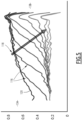
- the initial local volume profile 111 is then used to determine an initial profile 120 of the saturation in the first fluid, represented on figure 5 .
- the initial profile 120 corresponds to the steady state profile established in the porous sample 10, and is used to determine the initial local saturation Sgi in the first fluid.
- the porous sample 10 is then transferred to the measuring apparatus 16 receiving the reservoir 90.
- the porous sample 10 is placed in the reservoir 90, advantageously with the first end 13A submerged in the second fluid and oriented downward.
- the upper part of the porous sample 10 protrudes upwardly out of the reservoir 90.
- this orientation reduces the risk of a gravity-induced fluid migration modifying the profile of saturation in the first fluid in the porous sample.
- the capillary rise apparatus 18 generates a rise of a capillary ascension flow of the second fluid from the reservoir 90 through the sample, from the first end 13A toward the second end 13B.
- the measurement apparatus 16 continuously measures the evolution of the local volume of the second fluid in each region of the porous sample 10 during the capillary ascension, in relation with the calibration profile. The measurement is done at successive instants, for example with a time period comprised between 5 min and 2 hours, until the local volume of the second fluid is substantially steady in each region of the porous sample 10.
- An evolution of the local volume of the second fluid as a function of position and time is recorded in the calculator 20, and used to determine an evolution of the profile of the saturation in the second fluid in the porous sample 10, in reference to the calibration profile.
- each curve 112 is a profile of the saturation in the second fluid in the porous sample 10.
- the first end 13A is located on the left of the plot and the second end 13B on the right of the plot.
- the curves 112 representing the volume in the second fluid during the capillary ascension are arranged following the arrow 114, relative to the time, at successive instants in which the measurement was carried out.
- the saturation in the first fluid in each region is obtained from the saturation in the second fluid as their sum is equal to one.
- the evolution of the saturation in the first fluid is plotted on figure 5 , with each curve 116 being a profile of the saturation in the porous sample 10.
- the curves 116 representing the saturation in the first fluid during the capillary ascension are arranged following the arrow 118, relative to the time.
- the initial saturation Sgi in the first fluid is taken as the saturation in the first fluid in the initial profile 120 obtained before the capillary ascension step.
- the data analysis module of the calculator 20 determines a curve 124 of the evolution of the saturation in the first fluid plotted against the square root of time, as shown in figure 6 .
- the curve 124 presents a sharp drop 126 followed by a plateau 128, corresponding respectively to a capillary ascension regime and to a diffusion driven regime.
- the tangents to the curve are determined close to the transition, and the value of the saturation in first fluid corresponding to their crossing 130 is taken as the residual saturation Sgr in the first fluid in the region.
- the data analysis module of the calculator determines the Sgi/Sgr curve, plotted on figure 7 .
- Each region of the porous sample 10 in which a measurement was made at different instants during imbibition of the sample corresponds to a point in the Sgi/Sgr curve, plotted on figure 7 .
- the rotation speed ⁇ of the centrifuge 50 is modified, in order to reach a different steady-state profile and thus a different initial profile 120 of saturation in the first fluid.
- the method according to the invention allows a significant number of points of the Sgi/Sgr curve to be measured simultaneously in the same porous sample 10. With a typical number of regions in the porous sample around 400, the Sgi/Sgr relation curve is thus populated much faster than with previously existing experimental methods.
- the method according to the invention is easy to carry out, and does not require a large amount of man force, and/or numerous porous samples 10.
- the experimental method circumvents the problems that arise with long saturation times with a fluid-gas mix, including dissolution and diffusion, which can alter the results significantly.
Landscapes
- Life Sciences & Earth Sciences (AREA)
- Chemical & Material Sciences (AREA)
- Health & Medical Sciences (AREA)
- Immunology (AREA)
- Pathology (AREA)
- Engineering & Computer Science (AREA)
- General Physics & Mathematics (AREA)
- General Health & Medical Sciences (AREA)
- Biochemistry (AREA)
- Analytical Chemistry (AREA)
- Physics & Mathematics (AREA)
- Medicinal Chemistry (AREA)
- Food Science & Technology (AREA)
- Environmental & Geological Engineering (AREA)
- General Life Sciences & Earth Sciences (AREA)
- Remote Sensing (AREA)
- Geology (AREA)
- Dispersion Chemistry (AREA)
- Analysing Materials By The Use Of Radiation (AREA)
- Sampling And Sample Adjustment (AREA)
Claims (15)
- Verfahren zur Bestimmung einer Beziehung zwischen einer Anfangssättigung (Sgi) und einer Restsättigung (Sgr) in einem ersten Fluid in einer porösen Probe (10), wobei das Verfahren die folgenden Schritte umfasst:- Bereitstellung einer porösen Probe (10);- wesentliche Sättigung der porösen Probe (10) mit einem zweiten Fluid;- Messen eines lokalen Volumens des zweiten Fluids in einer Vielzahl von Bereichen der porösen Probe (10), wobei die Bereiche transversale Scheiben der porösen Probe sind, die nacheinander in Längsrichtung der porösen Probe entnommen werden, wobei jede Scheibe durch zwei parallele Querebenen begrenzt wird, die senkrecht zur Mittelachse der porösen Probe verlaufen;- Erstellen eines stationären Zustandsprofils der Sättigung des ersten Fluids in der porösen Probe (10) durch Aufbringen einer mechanischen Belastung, wobei in jedem Bereich der Vielzahl von Bereichen eine unterschiedliche Anfangssättigung (Sgi) im ersten Fluid erzeugt wird;- Messen eines anfänglichen lokalen Volumens des zweiten Fluids in jedem Bereich der porösen Probe (10);- Erzeugen eines Anstiegs einer kapillaren Aufstiegsströmung des zweiten Fluids durch die poröse Probe (10);- während des Anstiegs der kapillaren Aufstiegsströmung gleichzeitig in jedem Bereich der Vielzahl von Bereichen ein lokales Volumen des zweiten Fluids und/oder des ersten Fluids zu aufeinanderfolgenden Zeitpunkten zu messen, vorteilhafterweise bis das lokale Volumen im Wesentlichen konstant ist;- Bestimmen des Verhältnisses zwischen der Anfangssättigung (Sgi) im ersten Fluid und der Restsättigung (Sgr) im ersten Fluid auf der Grundlage des lokalen Volumens, das zu aufeinanderfolgenden Zeitpunkten in jedem Bereich der Vielzahl von Bereichen gemessen wird.
- Verfahren nach Anspruch 1, wobei die mechanische Belastung durch Zentrifugieren der porösen Probe (10) um eine Rotationsachse (A-A') aufgebracht wird, wobei ein erstes Ende (13A) der porösen Probe (10) von der Rotationsachse (A-A') weg und ein zweites Ende (13B) der porösen Probe (10) zur Rotationsachse (A-A') hin orientiert ist.
- Verfahren nach einem der Ansprüche 1 und 2, wobei das Erstellen des stationären Zustandsprofils in der porösen Probe (10) umfasst:- Einspritzen des ersten Fluids in die poröse Probe (10) unter Bildung einer Eintrittsströmung;- gleichzeitiges Sammeln von Fluid aus der porösen Probe (10), wodurch ein Ausgangsstrom gebildet wird; und- Aufrechterhaltung der mechanischen Belastung, bis eine Ausgangsströmung im Wesentlichen Null wird.
- Verfahren nach einem der vorhergehenden Ansprüche, wobei das lokale Volumen des ersten Fluids und/oder des zweiten Fluids in jedem Bereich der Vielzahl von Bereichen durch Kernspintomographie oder Röntgentomographie gemessen wird.
- Verfahren nach einem der vorhergehenden Ansprüche, wobei das Erzeugen eines Anstiegs einer kapillaren Aufstiegsströmung des zweiten Fluids durch die poröse Probe (10) umfasst:- Eintauchen eines ersten Endes (13A) der porösen Probe (10) in das zweite Fluid, wobei das erste Ende (13A) in Bezug auf die Schwerkraft nach unten gerichtet ist und ein zweites Ende (13B) nach oben gerichtet ist;- Aufrechterhaltung eines konstanten Niveaus des zweiten Fluids um das erste Ende (13A) der porösen Probe (10) während eines kapillaren Aufstiegs des zweiten Fluids durch die poröse Probe (10).
- Verfahren nach Anspruch 5, wobei der konstante Pegel des zweiten Fluids in einer Ebene (P) mit einer zweiten Fluidzuführungsanordnung (92) aufrechterhalten wird, die eine obere Bürette (96) und eine untere Bürette (97) umfasst, die das zweite Fluid enthalten, wobei sich eine obere Oberfläche des zweiten Fluids in der unteren Bürette (96) in die Ebene (P) erstreckt und ein Auslass (99) der oberen Bürette (96) in die untere Bürette (97) mündet, in der Ebene (P) oder unterhalb der Ebene (P).
- Verfahren nach Anspruch 6, umfassend das Überwachen der Position einer oberen Fläche des zweiten Fluids in der oberen Bürette (96).
- Verfahren nach einem der vorhergehenden Ansprüche, wobei während des Anstiegs der kapillaren Aufstiegsströmung die gleichzeitige Messung des lokalen Volumens des zweiten Fluids und/oder des ersten Fluids in jedem Bereich der Vielzahl von Bereichen zu aufeinanderfolgenden Zeitpunkten durchgeführt wird, ohne die poröse Probe (10) zu bewegen.
- Verfahren nach einem der vorhergehenden Ansprüche, wobei in jedem Bereich der Vielzahl von Bereichen die Anfangssättigung (Sgi) in dem ersten Fluid als die Sättigung in dem ersten Fluid bestimmt wird, die dem anfänglichen lokalen Volumen entspricht, und die Restsättigung (Sgr) als die Sättigung in dem ersten Fluid bestimmt wird, die einer Kreuzung (130) der Tangenten an die Kurve (124) auf jeder Seite (126, 128) eines Regimewechsels im kapillaren Aufstieg durch die poröse Probe (10) entspricht.
- Verfahren nach einem der vorhergehenden Ansprüche, wobei das erste Fluid ein Gas und das zweite Fluid eine Flüssigkeit, vorzugsweise eine Flüssigkeit auf Wasserbasis, ist.
- Verfahren nach einem der vorhergehenden Ansprüche, wobei die poröse Probe (10) eine Formationsprobe, insbesondere eine Gesteinsprobe, ist.
- Verfahren nach einem der vorhergehenden Ansprüche, bei dem die poröse Probe (10) im Wesentlichen zylindrisch ist und eine zentrale Achse aufweist, wobei jeder Bereich der Vielzahl von Bereichen eine transversale Scheibe ist, die durch zwei parallele Ebenen senkrecht zur zentralen Achse begrenzt wird.
- Verfahren nach einem der vorhergehenden Ansprüche, wobei die Schritte des Erstellens eines stationären Zustandsprofils, des Erzeugens eines Anstiegs einer kapillaren Aufstiegsströmung und des Messens der lokalen Sättigung mit unterschiedlichen Werten der mechanischen Belastung während des Schritts des Erstellens eines stationären Zustandsprofils wiederholt werden.
- System (12) zum Bestimmen einer Beziehung zwischen einer Anfangssättigung (Sgi) und einer Restsättigung (Sgr) in einem ersten Fluid in einer porösen Probe (10), wobei das System (12) so konfiguriert ist, dass es das Verfahren nach Anspruch 1 durchführt und Folgendes umfasst:- eine Messvorrichtung (16) zum Messen eines lokalen Volumens eines zweiten Fluids in jedem Bereich einer Vielzahl von Bereichen der porösen Probe (10), wobei die Bereiche transversale Scheiben der porösen Probe sind, die nacheinander in Längsrichtung der porösen Probe entnommen werden, wobei jede Scheibe durch zwei parallele Querebenen begrenzt ist, die senkrecht zur Mittelachse der porösen Probe verlaufen;- eine Lastaufbringungsvorrichtung (14) zum Erstellen eines stationären Zustandsprofils einer Sättigung in dem ersten Fluid in der porösen Probe (10) durch Aufbringen einer mechanischen Belastung, um in jedem Bereich der Vielzahl von Bereichen eine unterschiedliche Sättigung in dem ersten Fluid zu erzeugen;- eine Kapillaraufstiegsvorrichtung (18) zur Erzeugung einer kapillaren Aufstiegsströmung des zweiten Fluids durch die poröse Probe (10);- einen Rechner (20) zum Bestimmen der Beziehung zwischen der Anfangssättigung (Sgi) und der Restsättigung (Sgr) in der porösen Probe (10) auf der Grundlage der gemessenen lokalen Volumina in jedem Bereich der Vielzahl von Bereichen.
- System (12) nach Anspruch 14, wobei die Messvorrichtung (16) ein Kernspinresonanz-Bildgeber ist, der einen Messhohlraum (80) umfasst, der zur Aufnahme der porösen Probe (10) in Kontakt mit der Kapillaraufstiegsvorrichtung (18) geeignet ist.
Priority Applications (2)
| Application Number | Priority Date | Filing Date | Title |
|---|---|---|---|
| EP18305514.4A EP3561480B1 (de) | 2018-04-25 | 2018-04-25 | Verfahren zur bestimmung eines zusammenhangs zwischen einer anfangssättigung und einer restsättigung in einem ersten fluid in einer porösen probe und zugehörige anordnung |
| US16/391,563 US12072272B2 (en) | 2018-04-25 | 2019-04-23 | Method for determining a relation between an initial saturation and a residual saturation in a first fluid in a porous sample and related assembly |
Applications Claiming Priority (1)
| Application Number | Priority Date | Filing Date | Title |
|---|---|---|---|
| EP18305514.4A EP3561480B1 (de) | 2018-04-25 | 2018-04-25 | Verfahren zur bestimmung eines zusammenhangs zwischen einer anfangssättigung und einer restsättigung in einem ersten fluid in einer porösen probe und zugehörige anordnung |
Publications (2)
| Publication Number | Publication Date |
|---|---|
| EP3561480A1 EP3561480A1 (de) | 2019-10-30 |
| EP3561480B1 true EP3561480B1 (de) | 2024-06-12 |
Family
ID=62143073
Family Applications (1)
| Application Number | Title | Priority Date | Filing Date |
|---|---|---|---|
| EP18305514.4A Active EP3561480B1 (de) | 2018-04-25 | 2018-04-25 | Verfahren zur bestimmung eines zusammenhangs zwischen einer anfangssättigung und einer restsättigung in einem ersten fluid in einer porösen probe und zugehörige anordnung |
Country Status (2)
| Country | Link |
|---|---|
| US (1) | US12072272B2 (de) |
| EP (1) | EP3561480B1 (de) |
Families Citing this family (4)
| Publication number | Priority date | Publication date | Assignee | Title |
|---|---|---|---|---|
| CN111157405B (zh) * | 2020-01-10 | 2020-11-17 | 西南石油大学 | 基于手摇式升降装置的天然气扩散系数测量辅助装置 |
| CN111766181B (zh) * | 2020-06-29 | 2023-05-12 | 东北电力大学 | 原位水生态营养盐沉积物-上覆水界面迁移转化模拟系统 |
| CN114814160B (zh) * | 2021-01-29 | 2024-08-27 | 中国石油天然气股份有限公司 | 一种能够实现在线观测的岩石流体充注实验装置及方法 |
| CN117330459B (zh) * | 2023-12-01 | 2024-03-08 | 中国石油大学(华东) | 一种活油渗析实验方法 |
Family Cites Families (8)
| Publication number | Priority date | Publication date | Assignee | Title |
|---|---|---|---|---|
| US4868500A (en) | 1988-06-08 | 1989-09-19 | Phillips Petroleum Company | Method for determining properties of liquid-containing porous media using nuclear magnetic resonance imaging |
| US7352179B2 (en) | 2004-10-29 | 2008-04-01 | Green Imaging Technologies Inc. | Methods and apparatus for measuring capillary pressure in a sample |
| US7567079B2 (en) | 2007-06-08 | 2009-07-28 | University Of New Brunswick | Methods suitable for measuring capillary pressure and relative permeability curves of porous rocks |
| CA2806460C (en) * | 2010-08-06 | 2018-06-12 | Bp Exploration Operating Company Limited | Apparatus and method for testing multiple samples |
| GB2489205B (en) | 2011-03-14 | 2014-08-20 | Schlumberger Holdings | Examining porous samples |
| GB2505232B (en) | 2012-08-23 | 2018-08-01 | Schlumberger Holdings | Magnetic resonance examination of porous samples |
| ITMI20131986A1 (it) | 2013-11-28 | 2015-05-29 | Eni Spa | Metodo per la misurazione della saturazione in gas intrappolato in un campione di roccia |
| CN107831186B (zh) | 2017-09-28 | 2019-09-20 | 同济大学 | 岩芯毛细压力与饱和度曲线、油气藏参数的一维1h核磁共振成像测量表征方法 |
-
2018
- 2018-04-25 EP EP18305514.4A patent/EP3561480B1/de active Active
-
2019
- 2019-04-23 US US16/391,563 patent/US12072272B2/en active Active
Also Published As
| Publication number | Publication date |
|---|---|
| EP3561480A1 (de) | 2019-10-30 |
| US12072272B2 (en) | 2024-08-27 |
| US20190331578A1 (en) | 2019-10-31 |
Similar Documents
| Publication | Publication Date | Title |
|---|---|---|
| US12072272B2 (en) | Method for determining a relation between an initial saturation and a residual saturation in a first fluid in a porous sample and related assembly | |
| US7412875B2 (en) | Centrifuge permeameter for unsaturated soils system | |
| CN105793698B (zh) | 测量岩石样品中捕集气体饱和率的方法 | |
| AU2006223089B2 (en) | Determination of coal bed natural gas production factors and a system to determine same | |
| EP1655617B1 (de) | Verfahren und Gerät zum Messen des Kapillardrucks in einer Probe | |
| Roetting et al. | Changes in porosity, permeability, water retention curve and reactive surface area during carbonate rock dissolution | |
| US20160202230A1 (en) | Measurement of formation rock properties by diffusion | |
| CN107727679A (zh) | 一种表征深层碳酸盐岩岩石物理学特征方法 | |
| CN105765380A (zh) | 三轴离心机装置 | |
| Nguyen et al. | Microfluidics underground: a micro-core method for pore scale analysis of supercritical CO2 reactive transport in saline aquifers | |
| CN109459556A (zh) | 动态渗吸装置和用于动态渗吸实验的实验方法 | |
| BR112018014118B1 (pt) | Sistema e processo de medida de uma propriedade de escoamento de um fluido no seio de um meio poroso | |
| EP3612864B1 (de) | Verfahren zur bestimmung eines repräsentativen parameters einer porösen probe und zugehörige anordnung | |
| EP3020916A1 (de) | Verfahren zur Verarbeitung von während einer Mud-Logging-Analyse gesammelten Daten, zugehöriges Berechnungssystem und zugehörige Mud-Logging-Installation | |
| Layton et al. | Development of a passive sensor for measuring vertical cumulative water and solute mass fluxes in lake sediments and streambeds | |
| CN208155804U (zh) | 基于核磁共振的致密储层岩电测量装置 | |
| US20070131023A1 (en) | Centrifuge permeameter for unsaturated soils system | |
| Qajar et al. | Characterization of reactive flow-induced evolution of carbonate rocks using digital core analysis-part 2: Calculation of the evolution of percolation and transport properties | |
| CN112986074A (zh) | 钻井液沉降稳定性测试系统 | |
| Cha et al. | Low field NMR based relative permeability and drying model for unsaturated granular materials | |
| EP4220241A1 (de) | Grundwasserstrommessmodul | |
| US12111277B2 (en) | Method to determine a representative parameter of a porous sample and related system | |
| Todorovic et al. | The effect of brine supply on CO2 injectivity impairment due to salt precipitation | |
| CN119355243B (zh) | 未固结成岩储层原位成藏富集模拟实验装置及测量方法 | |
| Masihi | Reservoir rock properties analysis |
Legal Events
| Date | Code | Title | Description |
|---|---|---|---|
| STAA | Information on the status of an ep patent application or granted ep patent |
Free format text: STATUS: UNKNOWN |
|
| PUAI | Public reference made under article 153(3) epc to a published international application that has entered the european phase |
Free format text: ORIGINAL CODE: 0009012 |
|
| STAA | Information on the status of an ep patent application or granted ep patent |
Free format text: STATUS: THE APPLICATION HAS BEEN PUBLISHED |
|
| STAA | Information on the status of an ep patent application or granted ep patent |
Free format text: STATUS: REQUEST FOR EXAMINATION WAS MADE |
|
| AK | Designated contracting states |
Kind code of ref document: A1 Designated state(s): AL AT BE BG CH CY CZ DE DK EE ES FI FR GB GR HR HU IE IS IT LI LT LU LV MC MK MT NL NO PL PT RO RS SE SI SK SM TR |
|
| AX | Request for extension of the european patent |
Extension state: BA ME |
|
| 17P | Request for examination filed |
Effective date: 20191010 |
|
| RBV | Designated contracting states (corrected) |
Designated state(s): AL AT BE BG CH CY CZ DE DK EE ES FI FR GB GR HR HU IE IS IT LI LT LU LV MC MK MT NL NO PL PT RO RS SE SI SK SM TR |
|
| RAP1 | Party data changed (applicant data changed or rights of an application transferred) |
Owner name: TOTAL SE |
|
| STAA | Information on the status of an ep patent application or granted ep patent |
Free format text: STATUS: EXAMINATION IS IN PROGRESS |
|
| 17Q | First examination report despatched |
Effective date: 20220209 |
|
| RAP1 | Party data changed (applicant data changed or rights of an application transferred) |
Owner name: TOTALENERGIES ONETECH |
|
| GRAP | Despatch of communication of intention to grant a patent |
Free format text: ORIGINAL CODE: EPIDOSNIGR1 |
|
| STAA | Information on the status of an ep patent application or granted ep patent |
Free format text: STATUS: GRANT OF PATENT IS INTENDED |
|
| INTG | Intention to grant announced |
Effective date: 20240118 |
|
| P01 | Opt-out of the competence of the unified patent court (upc) registered |
Effective date: 20240224 |
|
| GRAS | Grant fee paid |
Free format text: ORIGINAL CODE: EPIDOSNIGR3 |
|
| GRAA | (expected) grant |
Free format text: ORIGINAL CODE: 0009210 |
|
| STAA | Information on the status of an ep patent application or granted ep patent |
Free format text: STATUS: THE PATENT HAS BEEN GRANTED |
|
| AK | Designated contracting states |
Kind code of ref document: B1 Designated state(s): AL AT BE BG CH CY CZ DE DK EE ES FI FR GB GR HR HU IE IS IT LI LT LU LV MC MK MT NL NO PL PT RO RS SE SI SK SM TR |
|
| REG | Reference to a national code |
Ref country code: GB Ref legal event code: FG4D |
|
| REG | Reference to a national code |
Ref country code: CH Ref legal event code: EP |
|
| REG | Reference to a national code |
Ref country code: IE Ref legal event code: FG4D |
|
| REG | Reference to a national code |
Ref country code: DE Ref legal event code: R096 Ref document number: 602018070475 Country of ref document: DE |
|
| REG | Reference to a national code |
Ref country code: NL Ref legal event code: FP |
|
| PG25 | Lapsed in a contracting state [announced via postgrant information from national office to epo] |
Ref country code: BG Free format text: LAPSE BECAUSE OF FAILURE TO SUBMIT A TRANSLATION OF THE DESCRIPTION OR TO PAY THE FEE WITHIN THE PRESCRIBED TIME-LIMIT Effective date: 20240612 |
|
| PG25 | Lapsed in a contracting state [announced via postgrant information from national office to epo] |
Ref country code: HR Free format text: LAPSE BECAUSE OF FAILURE TO SUBMIT A TRANSLATION OF THE DESCRIPTION OR TO PAY THE FEE WITHIN THE PRESCRIBED TIME-LIMIT Effective date: 20240612 Ref country code: FI Free format text: LAPSE BECAUSE OF FAILURE TO SUBMIT A TRANSLATION OF THE DESCRIPTION OR TO PAY THE FEE WITHIN THE PRESCRIBED TIME-LIMIT Effective date: 20240612 |
|
| REG | Reference to a national code |
Ref country code: LT Ref legal event code: MG9D |
|
| PG25 | Lapsed in a contracting state [announced via postgrant information from national office to epo] |
Ref country code: GR Free format text: LAPSE BECAUSE OF FAILURE TO SUBMIT A TRANSLATION OF THE DESCRIPTION OR TO PAY THE FEE WITHIN THE PRESCRIBED TIME-LIMIT Effective date: 20240913 |
|
| PG25 | Lapsed in a contracting state [announced via postgrant information from national office to epo] |
Ref country code: ES Free format text: LAPSE BECAUSE OF FAILURE TO SUBMIT A TRANSLATION OF THE DESCRIPTION OR TO PAY THE FEE WITHIN THE PRESCRIBED TIME-LIMIT Effective date: 20240612 |
|
| PG25 | Lapsed in a contracting state [announced via postgrant information from national office to epo] |
Ref country code: LV Free format text: LAPSE BECAUSE OF FAILURE TO SUBMIT A TRANSLATION OF THE DESCRIPTION OR TO PAY THE FEE WITHIN THE PRESCRIBED TIME-LIMIT Effective date: 20240612 |
|
| PG25 | Lapsed in a contracting state [announced via postgrant information from national office to epo] |
Ref country code: LV Free format text: LAPSE BECAUSE OF FAILURE TO SUBMIT A TRANSLATION OF THE DESCRIPTION OR TO PAY THE FEE WITHIN THE PRESCRIBED TIME-LIMIT Effective date: 20240612 Ref country code: HR Free format text: LAPSE BECAUSE OF FAILURE TO SUBMIT A TRANSLATION OF THE DESCRIPTION OR TO PAY THE FEE WITHIN THE PRESCRIBED TIME-LIMIT Effective date: 20240612 Ref country code: GR Free format text: LAPSE BECAUSE OF FAILURE TO SUBMIT A TRANSLATION OF THE DESCRIPTION OR TO PAY THE FEE WITHIN THE PRESCRIBED TIME-LIMIT Effective date: 20240913 Ref country code: FI Free format text: LAPSE BECAUSE OF FAILURE TO SUBMIT A TRANSLATION OF THE DESCRIPTION OR TO PAY THE FEE WITHIN THE PRESCRIBED TIME-LIMIT Effective date: 20240612 Ref country code: ES Free format text: LAPSE BECAUSE OF FAILURE TO SUBMIT A TRANSLATION OF THE DESCRIPTION OR TO PAY THE FEE WITHIN THE PRESCRIBED TIME-LIMIT Effective date: 20240612 Ref country code: BG Free format text: LAPSE BECAUSE OF FAILURE TO SUBMIT A TRANSLATION OF THE DESCRIPTION OR TO PAY THE FEE WITHIN THE PRESCRIBED TIME-LIMIT Effective date: 20240612 Ref country code: RS Free format text: LAPSE BECAUSE OF FAILURE TO SUBMIT A TRANSLATION OF THE DESCRIPTION OR TO PAY THE FEE WITHIN THE PRESCRIBED TIME-LIMIT Effective date: 20240912 |
|
| REG | Reference to a national code |
Ref country code: AT Ref legal event code: MK05 Ref document number: 1694666 Country of ref document: AT Kind code of ref document: T Effective date: 20240612 |
|
| PG25 | Lapsed in a contracting state [announced via postgrant information from national office to epo] |
Ref country code: PT Free format text: LAPSE BECAUSE OF FAILURE TO SUBMIT A TRANSLATION OF THE DESCRIPTION OR TO PAY THE FEE WITHIN THE PRESCRIBED TIME-LIMIT Effective date: 20241014 |
|
| PG25 | Lapsed in a contracting state [announced via postgrant information from national office to epo] |
Ref country code: PT Free format text: LAPSE BECAUSE OF FAILURE TO SUBMIT A TRANSLATION OF THE DESCRIPTION OR TO PAY THE FEE WITHIN THE PRESCRIBED TIME-LIMIT Effective date: 20241014 |
|
| PG25 | Lapsed in a contracting state [announced via postgrant information from national office to epo] |
Ref country code: PL Free format text: LAPSE BECAUSE OF FAILURE TO SUBMIT A TRANSLATION OF THE DESCRIPTION OR TO PAY THE FEE WITHIN THE PRESCRIBED TIME-LIMIT Effective date: 20240612 |
|
| PG25 | Lapsed in a contracting state [announced via postgrant information from national office to epo] |
Ref country code: EE Free format text: LAPSE BECAUSE OF FAILURE TO SUBMIT A TRANSLATION OF THE DESCRIPTION OR TO PAY THE FEE WITHIN THE PRESCRIBED TIME-LIMIT Effective date: 20240612 |
|
| PG25 | Lapsed in a contracting state [announced via postgrant information from national office to epo] |
Ref country code: AT Free format text: LAPSE BECAUSE OF FAILURE TO SUBMIT A TRANSLATION OF THE DESCRIPTION OR TO PAY THE FEE WITHIN THE PRESCRIBED TIME-LIMIT Effective date: 20240612 Ref country code: IS Free format text: LAPSE BECAUSE OF FAILURE TO SUBMIT A TRANSLATION OF THE DESCRIPTION OR TO PAY THE FEE WITHIN THE PRESCRIBED TIME-LIMIT Effective date: 20241012 |
|
| PG25 | Lapsed in a contracting state [announced via postgrant information from national office to epo] |
Ref country code: CZ Free format text: LAPSE BECAUSE OF FAILURE TO SUBMIT A TRANSLATION OF THE DESCRIPTION OR TO PAY THE FEE WITHIN THE PRESCRIBED TIME-LIMIT Effective date: 20240612 |
|
| PG25 | Lapsed in a contracting state [announced via postgrant information from national office to epo] |
Ref country code: RO Free format text: LAPSE BECAUSE OF FAILURE TO SUBMIT A TRANSLATION OF THE DESCRIPTION OR TO PAY THE FEE WITHIN THE PRESCRIBED TIME-LIMIT Effective date: 20240612 Ref country code: SK Free format text: LAPSE BECAUSE OF FAILURE TO SUBMIT A TRANSLATION OF THE DESCRIPTION OR TO PAY THE FEE WITHIN THE PRESCRIBED TIME-LIMIT Effective date: 20240612 |
|
| PG25 | Lapsed in a contracting state [announced via postgrant information from national office to epo] |
Ref country code: SM Free format text: LAPSE BECAUSE OF FAILURE TO SUBMIT A TRANSLATION OF THE DESCRIPTION OR TO PAY THE FEE WITHIN THE PRESCRIBED TIME-LIMIT Effective date: 20240612 |
|
| PG25 | Lapsed in a contracting state [announced via postgrant information from national office to epo] |
Ref country code: SM Free format text: LAPSE BECAUSE OF FAILURE TO SUBMIT A TRANSLATION OF THE DESCRIPTION OR TO PAY THE FEE WITHIN THE PRESCRIBED TIME-LIMIT Effective date: 20240612 Ref country code: SK Free format text: LAPSE BECAUSE OF FAILURE TO SUBMIT A TRANSLATION OF THE DESCRIPTION OR TO PAY THE FEE WITHIN THE PRESCRIBED TIME-LIMIT Effective date: 20240612 Ref country code: RO Free format text: LAPSE BECAUSE OF FAILURE TO SUBMIT A TRANSLATION OF THE DESCRIPTION OR TO PAY THE FEE WITHIN THE PRESCRIBED TIME-LIMIT Effective date: 20240612 Ref country code: PL Free format text: LAPSE BECAUSE OF FAILURE TO SUBMIT A TRANSLATION OF THE DESCRIPTION OR TO PAY THE FEE WITHIN THE PRESCRIBED TIME-LIMIT Effective date: 20240612 Ref country code: IS Free format text: LAPSE BECAUSE OF FAILURE TO SUBMIT A TRANSLATION OF THE DESCRIPTION OR TO PAY THE FEE WITHIN THE PRESCRIBED TIME-LIMIT Effective date: 20241012 Ref country code: EE Free format text: LAPSE BECAUSE OF FAILURE TO SUBMIT A TRANSLATION OF THE DESCRIPTION OR TO PAY THE FEE WITHIN THE PRESCRIBED TIME-LIMIT Effective date: 20240612 Ref country code: CZ Free format text: LAPSE BECAUSE OF FAILURE TO SUBMIT A TRANSLATION OF THE DESCRIPTION OR TO PAY THE FEE WITHIN THE PRESCRIBED TIME-LIMIT Effective date: 20240612 Ref country code: AT Free format text: LAPSE BECAUSE OF FAILURE TO SUBMIT A TRANSLATION OF THE DESCRIPTION OR TO PAY THE FEE WITHIN THE PRESCRIBED TIME-LIMIT Effective date: 20240612 |
|
| REG | Reference to a national code |
Ref country code: DE Ref legal event code: R097 Ref document number: 602018070475 Country of ref document: DE |
|
| PG25 | Lapsed in a contracting state [announced via postgrant information from national office to epo] |
Ref country code: DK Free format text: LAPSE BECAUSE OF FAILURE TO SUBMIT A TRANSLATION OF THE DESCRIPTION OR TO PAY THE FEE WITHIN THE PRESCRIBED TIME-LIMIT Effective date: 20240612 |
|
| PLBE | No opposition filed within time limit |
Free format text: ORIGINAL CODE: 0009261 |
|
| STAA | Information on the status of an ep patent application or granted ep patent |
Free format text: STATUS: NO OPPOSITION FILED WITHIN TIME LIMIT |
|
| PGFP | Annual fee paid to national office [announced via postgrant information from national office to epo] |
Ref country code: NL Payment date: 20250418 Year of fee payment: 8 |
|
| 26N | No opposition filed |
Effective date: 20250313 |
|
| PGFP | Annual fee paid to national office [announced via postgrant information from national office to epo] |
Ref country code: NO Payment date: 20250424 Year of fee payment: 8 |
|
| PGFP | Annual fee paid to national office [announced via postgrant information from national office to epo] |
Ref country code: IT Payment date: 20250424 Year of fee payment: 8 |
|
| PGFP | Annual fee paid to national office [announced via postgrant information from national office to epo] |
Ref country code: FR Payment date: 20250425 Year of fee payment: 8 |
|
| PG25 | Lapsed in a contracting state [announced via postgrant information from national office to epo] |
Ref country code: SE Free format text: LAPSE BECAUSE OF FAILURE TO SUBMIT A TRANSLATION OF THE DESCRIPTION OR TO PAY THE FEE WITHIN THE PRESCRIBED TIME-LIMIT Effective date: 20240612 |
|
| REG | Reference to a national code |
Ref country code: DE Ref legal event code: R119 Ref document number: 602018070475 Country of ref document: DE |
|
| REG | Reference to a national code |
Ref country code: CH Ref legal event code: H13 Free format text: ST27 STATUS EVENT CODE: U-0-0-H10-H13 (AS PROVIDED BY THE NATIONAL OFFICE) Effective date: 20251125 |
|
| PG25 | Lapsed in a contracting state [announced via postgrant information from national office to epo] |
Ref country code: LU Free format text: LAPSE BECAUSE OF NON-PAYMENT OF DUE FEES Effective date: 20250425 |
|
| PG25 | Lapsed in a contracting state [announced via postgrant information from national office to epo] |
Ref country code: MC Free format text: LAPSE BECAUSE OF FAILURE TO SUBMIT A TRANSLATION OF THE DESCRIPTION OR TO PAY THE FEE WITHIN THE PRESCRIBED TIME-LIMIT Effective date: 20240612 |
|
| REG | Reference to a national code |
Ref country code: BE Ref legal event code: MM Effective date: 20250430 |
|
| PG25 | Lapsed in a contracting state [announced via postgrant information from national office to epo] |
Ref country code: DE Free format text: LAPSE BECAUSE OF NON-PAYMENT OF DUE FEES Effective date: 20251104 |
|
| PG25 | Lapsed in a contracting state [announced via postgrant information from national office to epo] |
Ref country code: BE Free format text: LAPSE BECAUSE OF NON-PAYMENT OF DUE FEES Effective date: 20250430 |
|
| PG25 | Lapsed in a contracting state [announced via postgrant information from national office to epo] |
Ref country code: CH Free format text: LAPSE BECAUSE OF NON-PAYMENT OF DUE FEES Effective date: 20250430 |
|
| PGFP | Annual fee paid to national office [announced via postgrant information from national office to epo] |
Ref country code: GB Payment date: 20260306 Year of fee payment: 9 |
|
| PG25 | Lapsed in a contracting state [announced via postgrant information from national office to epo] |
Ref country code: IE Free format text: LAPSE BECAUSE OF NON-PAYMENT OF DUE FEES Effective date: 20250425 |