EP3561575A1 - Scharnier ohne zapfenschraube für brillengestell - Google Patents
Scharnier ohne zapfenschraube für brillengestell Download PDFInfo
- Publication number
- EP3561575A1 EP3561575A1 EP19170522.7A EP19170522A EP3561575A1 EP 3561575 A1 EP3561575 A1 EP 3561575A1 EP 19170522 A EP19170522 A EP 19170522A EP 3561575 A1 EP3561575 A1 EP 3561575A1
- Authority
- EP
- European Patent Office
- Prior art keywords
- branch
- hinge
- face
- frame
- curved
- Prior art date
- Legal status (The legal status is an assumption and is not a legal conclusion. Google has not performed a legal analysis and makes no representation as to the accuracy of the status listed.)
- Withdrawn
Links
- 239000011521 glass Substances 0.000 claims abstract description 11
- 238000012423 maintenance Methods 0.000 claims description 5
- 239000007769 metal material Substances 0.000 claims description 4
- 230000000694 effects Effects 0.000 description 6
- 238000003780 insertion Methods 0.000 description 2
- 230000037431 insertion Effects 0.000 description 2
- 239000002184 metal Substances 0.000 description 2
- 229910052751 metal Inorganic materials 0.000 description 2
- 230000002093 peripheral effect Effects 0.000 description 2
- RTAQQCXQSZGOHL-UHFFFAOYSA-N Titanium Chemical compound [Ti] RTAQQCXQSZGOHL-UHFFFAOYSA-N 0.000 description 1
- 230000000903 blocking effect Effects 0.000 description 1
- 210000005069 ears Anatomy 0.000 description 1
- 238000004519 manufacturing process Methods 0.000 description 1
- 230000001681 protective effect Effects 0.000 description 1
- 229910001220 stainless steel Inorganic materials 0.000 description 1
- 239000010935 stainless steel Substances 0.000 description 1
- 239000010936 titanium Substances 0.000 description 1
- 229910052719 titanium Inorganic materials 0.000 description 1
- 230000007704 transition Effects 0.000 description 1
Images


Classifications
-
- G—PHYSICS
- G02—OPTICS
- G02C—SPECTACLES; SUNGLASSES OR GOGGLES INSOFAR AS THEY HAVE THE SAME FEATURES AS SPECTACLES; CONTACT LENSES
- G02C5/00—Constructions of non-optical parts
- G02C5/14—Side-members
- G02C5/146—Side-members having special front end
-
- G—PHYSICS
- G02—OPTICS
- G02C—SPECTACLES; SUNGLASSES OR GOGGLES INSOFAR AS THEY HAVE THE SAME FEATURES AS SPECTACLES; CONTACT LENSES
- G02C5/00—Constructions of non-optical parts
- G02C5/22—Hinges
- G02C5/2209—Pivot bearings and hinge bolts other than screws
-
- G—PHYSICS
- G02—OPTICS
- G02C—SPECTACLES; SUNGLASSES OR GOGGLES INSOFAR AS THEY HAVE THE SAME FEATURES AS SPECTACLES; CONTACT LENSES
- G02C2200/00—Generic mechanical aspects applicable to one or more of the groups G02C1/00 - G02C5/00 and G02C9/00 - G02C13/00 and their subgroups
- G02C2200/12—Frame or frame portions made from sheet type material
-
- G—PHYSICS
- G02—OPTICS
- G02C—SPECTACLES; SUNGLASSES OR GOGGLES INSOFAR AS THEY HAVE THE SAME FEATURES AS SPECTACLES; CONTACT LENSES
- G02C2200/00—Generic mechanical aspects applicable to one or more of the groups G02C1/00 - G02C5/00 and G02C9/00 - G02C13/00 and their subgroups
- G02C2200/22—Leaf spring
Definitions
- the present invention relates to eyeglass frames, and more particularly to a screwless hinge for the manufacture of eyeglass frames and the fitting of the eyeglass arms to the frame.
- a pair of glasses has a frame on which glasses are mounted.
- the mount is a frame comprising an outer and an inner face, generally designated by the term of face of the frame, and two branches.
- the face of the frame allows to receive and hold the glasses, while the branches, placed on the ears, ensure the stability of the glasses.
- Each of the two branches is assembled at one of the two ends of the face using a hinge.
- the hinge allows, on the one hand, to fold the branch against the face to reduce the size of the pair of glasses before storing in a housing, and secondly, to unfold the branch in a position in which the branch can be placed on a user's ear.
- hinges useful for assembling the branches of a mount to the face. Most often, the assembly is performed using a hinge pivot screw, that is to say a hinge using a screw around which the hinge pivots.
- Hinges having a pivot screw have disadvantages. When the screw is too tight, the hinge is hard to operate. When the screw is not tight enough, however, the screw can easily come off.
- Such a hinge does not have good vertical stability, due to the fact that the spiral of the branch has only one attachment point on the face.
- a hinge without a pivot screw comprising a first member having a spiral end, a second member forming a through hole and a bearing wall for the spiral end of the first member, and a third member for locking the second element, which is formed by an assembly of two distinct parts, and to form a groove for receiving the spiral end of the first element.
- the screwless hinge described in this document has only one attachment point between the first element and the second element, the first element passing through the second element only in one place. Therefore, the branch does not have a very good vertical locking of the branch relative to the face of the frame without the third element.
- an eyeglass frame branch comprising a hinge without screws
- the hinge comprises two slots open at one of their ends to define three metal strips each having a free end, the band between the two peripheral strips deviate from the plane comprising the two peripheral bands when the branch is folded.
- the invention aims to provide an improved hinge without pivot screw, used to assemble a branch to a face of a frame of a pair of glasses and to present a good vertical locking while using an element.
- the invention thus relates to a hinge without pivot screw for eyeglass frame comprising a hinge element intended to be mounted on a branch of a spectacle frame and on the face of said frame, thereby forming an articulated hinge suitable for allow the articulation of the arm of the frame between a first position in which the arm of the frame is in the open position allowing the wearing of glasses and a second position in which the arm is retracted in closed position against the face of the frame.
- the hinge element comprises two mutually opposite ends, one in the shape of a hook and the other in the form of a loop, so that the whole of the element forms a clamp.
- the hinge element Passing into the branch through a hole, the hinge element allows the junction with the face of the frame being then clipped into two holes of the face, allowing the maintenance of the assembly.
- the hinge element ensures a good locking and pivoting of the branch between the first position and the second position, without the element pivots.
- the hinge element comprises a band curved so as to define an insertion opening to pass the branch.
- the curved strip preferably comprises two ends themselves curved, intended to be mounted on the face of the frame.
- the first end is bent L-shaped like a hook, which allows the passage of the element through the hole of the branch and the attachment of the element in the first hole of the face of the frame.
- the second end has a spiral shape intended to be inserted in the front face of the frame by the second orifice, allowing through the second attachment point, the locking of the element and the maintenance of the assembly to allow the branch to rotate without turning the element.
- the whole forms a hinge.
- the two curved ends of the element are configured to provide a spring effect of the hinge and the pivot of the branch, that is to say form a spring internal to the hinge, when the branch is in an intermediate position between the first position and the second position so as to return the branch to the first position or the second position.
- the spring effect provided by the hinge thus facilitates the change of position of the branches of the frame using said hinges.
- the spring effect also makes sure that the branch is not blocked in the first or second position.
- the hinge element comprises two ends, sufficiently spaced apart to be inserted through the orifice of the branch and the orifices of the face of the frame.
- a possible configuration of the hinge to provide the spring effect is to size the U-shaped member so that the distance between the parallel arms of the U is equal to the length of the distance between the head of the branch and the beginning of the the orifice of the branch and that the space between the outer parallel and the base of the U facing the respective sides of the frame is equal to the thickness of the upper part of the branch.
- the branch can rotate to abut on the face of the frame in the first position and in second position.
- the parallels of the element as the base can advantageously be sized according to the aesthetic measures of the branch and the face to allow locking in the first position or in the second position.
- the longitudinal dimensions and their spacings thus define the first position and the second position, while ensuring locking in the first position or in the second position, the hinge being pivotable only between the two positions and only over a given angular range .
- the element can be made of a metallic material.
- the metallic material used may be stainless steel or titanium.
- the metal has significant strength for a reduced thickness, and a relatively low weight.
- FIG. 1 On the figure 1 is illustrated a perspective view of a hinge element 1 according to one embodiment of the invention.
- This hinge element is intended to allow the assembly of a branch of glasses on a mount.
- the first arm 2 of the element 1 comprises a free end 5 curved inwardly in the plane of the element while the other arm 11 comprises a hook-shaped straight end 4 extending in parallel. at the base and facing outward from the hinge element.
- the second end 4 is connected to the first end 5 by the portions 2, 3, and 11.
- the arm 2, located in the extension of the first end 5 is parallel to the arm 11, located in the extension of the second end 4 in the form of a hook via a curved portion 7.
- the second end 4 is perpendicular to the arm 11, thus forming a hook.
- the arm 2 is connected to the arm 11 by the base 3 which is perpendicular to the arms 2 and 3 and is connected thereto via curved portions 8 and 10 forming a U whose base is flat.
- the spiral portion 9 of the first end 5 is opposite the curved portion 7, so as to define a passage 6.
- FIG 2 On the figure 2 is shown a perspective view of a hinge 16 made from the hinge element of the figure 1 before assembly with the face 14 and the branch 15 of a spectacle frame.
- the spectacle frame branch 15 comprises a transverse orifice 17 made in the vicinity of the end of the branch intended to be articulated on the frame. This orifice is extended by a longitudinal groove made in the outer face of the branch and which opens at the end of the branch. This groove delimits internally a stop 12.
- the orifice 17 is intended to receive the right end 4 of the hinge element and the groove is intended to receive the arm 2.
- This configuration thus allows the element 1 to be mounted by the passage of the second end 4 of the element 1 in the orifice 17 and by the insertion of the stop 12 of the branch 15 in passage 6.
- the face 14 of the spectacle frame comprises a first orifice 18 and a second orifice 13.
- the orifice 18 of the face 14 is configured to receive the second end 4 of the element 1 after passing through the orifice 17 and the orifice 13 of the face 14 is configured to receive the first end 5 of element 1.
- the orifices 18 and 13 of the face 14 are dimensioned to allow good maintenance and stability of the element 1 and the hinge 16.
- the figure 3 illustrates the spectacle frame in its first open position, for positioning the frame on a face.
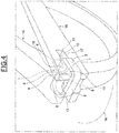
- the figure 4 illustrates the bezel frame in its second closed position, for storing the frame in a box as a protective case.
- the transition from the first position to the second position is effected by a possible rotation of the branch 15 inwardly with respect to the face 14 and, if it is desired to pass from the second position to the first position, the possible rotation of the branch 15 is effected outwardly with respect to the face 14.
- the element 1 allows the branch 15 to abut against the face 14 of the bezel mount in the first position as in the second position allowing rotation while maintaining the entire hinge 16.
- the stop in the first position obtained between the face 14 and the branch 15 is formed and held by the arm 2 and the base 3 of the element 1 and perpendicular to each other, forming a limited space for holding with the face 14, locking the portion 12 of the branch 15 abuts the face 14.
- the stop in second position obtained between the face 14 and the branch 15 is formed and maintained by the arms 2 and 11 and the base 3 of the element 1 forming a limited holding space with the face 14, locking the portion 12 of the branch 15 in abutment against the face 14.
- the element 1 remains fixed on the face of the orifice 13 giving a restricted angular range in a limited space, between the first position and the second position, constituting means for locking a spectacle frame.
- the lengths and the space limited by the arms 2, 11 and the base 3 are dimensioned to provide a spring effect to the hinge 16 when in a position between the first position and the second position while providing a good locking of the branch 15 against the face 14 in the first position and the second position.
- the dimensions of the element 1 depend on the dimensions chosen for the orifices 13 and 18 of the face 14 and the orifice 17 and the stop 12 of the branch 15 and the chosen aesthetic dimensions for branch 15 and side 14.
- variable thickness of the upper part of the branch 15 and the distance between the orifices of the face 14 and the length of the stop 12 of the branch 15, determine the proportions of the various parts of the element 1 to obtain a good locking in abutment in the first position and in the second position of the spectacle frame and thus allow the desired spring effect.
- the invention thus provides an improved hinge 16 without pivot screws that can be used to assemble a branch 15 to the face 14 of a spectacle frame with a single element making it possible, on the one hand, to prevent any vertical movement, that is to say along the horizontal axis of the element 1, and secondly, to block the branch in a first and second position only through the element 1 so that the pivot of the branch 15 does not go beyond these two positions and without the element 1 rotates.
- the invention thus relates to a hinge without screw pivot for eyeglass frame
- a hinge element in the form of a strip, intended to be mounted on a branch of a spectacle frame and on one face of the frame to be inserted into a port of the branch and into orifices of the face so as to lock the assembly in a first position in which the arm of the frame is in the open position allowing the wearing of glasses and a second position in which the branch is retracted in closed position against the face of the frame.
- the invention also relates to a frame for a pair of spectacles comprising at least one hinge without pivot screw as defined above.
Landscapes
- Physics & Mathematics (AREA)
- Health & Medical Sciences (AREA)
- General Physics & Mathematics (AREA)
- Ophthalmology & Optometry (AREA)
- Optics & Photonics (AREA)
- Eyeglasses (AREA)
Applications Claiming Priority (1)
| Application Number | Priority Date | Filing Date | Title |
|---|---|---|---|
| FR1853546A FR3080466A1 (fr) | 2018-04-23 | 2018-04-23 | Charniere sans vis de pivot pour monture de lunettes |
Publications (1)
| Publication Number | Publication Date |
|---|---|
| EP3561575A1 true EP3561575A1 (de) | 2019-10-30 |
Family
ID=65443888
Family Applications (1)
| Application Number | Title | Priority Date | Filing Date |
|---|---|---|---|
| EP19170522.7A Withdrawn EP3561575A1 (de) | 2018-04-23 | 2019-04-23 | Scharnier ohne zapfenschraube für brillengestell |
Country Status (2)
| Country | Link |
|---|---|
| EP (1) | EP3561575A1 (de) |
| FR (1) | FR3080466A1 (de) |
Citations (3)
| Publication number | Priority date | Publication date | Assignee | Title |
|---|---|---|---|---|
| EP1754097A1 (de) * | 2004-05-28 | 2007-02-21 | Mykita GmbH | Brillengestell |
| EP2116887A1 (de) * | 2008-05-08 | 2009-11-11 | Mykita Studio GmbH | Brillenbügel |
| EP2980631A1 (de) * | 2014-08-01 | 2016-02-03 | Christophe Kuntz | Scharnier ohne drehschraube für brillengestell |
-
2018
- 2018-04-23 FR FR1853546A patent/FR3080466A1/fr not_active Withdrawn
-
2019
- 2019-04-23 EP EP19170522.7A patent/EP3561575A1/de not_active Withdrawn
Patent Citations (3)
| Publication number | Priority date | Publication date | Assignee | Title |
|---|---|---|---|---|
| EP1754097A1 (de) * | 2004-05-28 | 2007-02-21 | Mykita GmbH | Brillengestell |
| EP2116887A1 (de) * | 2008-05-08 | 2009-11-11 | Mykita Studio GmbH | Brillenbügel |
| EP2980631A1 (de) * | 2014-08-01 | 2016-02-03 | Christophe Kuntz | Scharnier ohne drehschraube für brillengestell |
Also Published As
| Publication number | Publication date |
|---|---|
| FR3080466A1 (fr) | 2019-10-25 |
Similar Documents
| Publication | Publication Date | Title |
|---|---|---|
| FR2912516A1 (fr) | Charniere elastique compacte pour monture de lunettes | |
| CH702523B1 (fr) | Dispositif de réglage fin de la longueur utile d'un bracelet et fermoir correspondant. | |
| WO2017051092A1 (fr) | Monture électronique | |
| WO2015185831A1 (fr) | Monture de lunettes a branches en lames de métal amovibles clipsees | |
| FR2658231A1 (en) | Joint hinge | |
| EP2841986B1 (de) | Brillenfassung mit einem zierstück | |
| EP0865742B1 (de) | Faltverschluss für Armbänder | |
| EP2980631A1 (de) | Scharnier ohne drehschraube für brillengestell | |
| EP2007558A2 (de) | Klappbares gestell | |
| CA2716470A1 (fr) | Monture de lunette | |
| EP3561575A1 (de) | Scharnier ohne zapfenschraube für brillengestell | |
| EP1636632B1 (de) | Brillenrahmen mit armen, die weit um einen versetzten stützpunkt herum geöffnet werden können | |
| EP2963481A1 (de) | Scharnier eines brillengestells | |
| EP0892296A1 (de) | Federscharnier für einen flachen Brillenbügel | |
| EP4021241B1 (de) | Schmuckartikel | |
| FR2634153A1 (fr) | Mecanisme de cran d'arret pour lame de couteau de poche | |
| EP3469416A1 (de) | Scharnier für ein brillengestell mit mindestens einem internen anschlag | |
| FR3096714A3 (fr) | Charnière de type à peigne pour fenêtre et portes à vantail pivotant | |
| EP4541222A1 (de) | Faltverschluss für armband, insbesondere für armbanduhren | |
| FR2718537A1 (fr) | Charnière pour monture de lunettes avec basculement télescopique des branches. | |
| FR2770653A1 (fr) | Dispositif de fixation de branches sur face de lunettes, branche de lunettes et procede de fabrication de tenon | |
| BE1012184A3 (fr) | Charniere pour elements articules, notamment des elements articules de mobilier. | |
| WO2008029024A2 (fr) | Charniere ou articulation de lunettes a angle de fermeture reglable | |
| EP1605130A1 (de) | Fingerschutz | |
| FR3011345A1 (fr) | Monture de lunettes a branches articulees |
Legal Events
| Date | Code | Title | Description |
|---|---|---|---|
| PUAI | Public reference made under article 153(3) epc to a published international application that has entered the european phase |
Free format text: ORIGINAL CODE: 0009012 |
|
| AK | Designated contracting states |
Kind code of ref document: A1 Designated state(s): AL AT BE BG CH CY CZ DE DK EE ES FI FR GB GR HR HU IE IS IT LI LT LU LV MC MK MT NL NO PL PT RO RS SE SI SK SM TR |
|
| AX | Request for extension of the european patent |
Extension state: BA ME |
|
| STAA | Information on the status of an ep patent application or granted ep patent |
Free format text: STATUS: THE APPLICATION IS DEEMED TO BE WITHDRAWN |
|
| 18D | Application deemed to be withdrawn |
Effective date: 20200603 |