EP3561840B1 - Dispositif de commutation à isolation gazeuse - Google Patents
Dispositif de commutation à isolation gazeuse Download PDFInfo
- Publication number
- EP3561840B1 EP3561840B1 EP16923924.1A EP16923924A EP3561840B1 EP 3561840 B1 EP3561840 B1 EP 3561840B1 EP 16923924 A EP16923924 A EP 16923924A EP 3561840 B1 EP3561840 B1 EP 3561840B1
- Authority
- EP
- European Patent Office
- Prior art keywords
- contact
- gas
- fixed
- movable contact
- movable
- Prior art date
- Legal status (The legal status is an assumption and is not a legal conclusion. Google has not performed a legal analysis and makes no representation as to the accuracy of the status listed.)
- Active
Links
Images



Classifications
-
- H—ELECTRICITY
- H01—ELECTRIC ELEMENTS
- H01H—ELECTRIC SWITCHES; RELAYS; SELECTORS; EMERGENCY PROTECTIVE DEVICES
- H01H33/00—High-tension or heavy-current switches with arc-extinguishing or arc-preventing means
- H01H33/70—Switches with separate means for directing, obtaining, or increasing flow of arc-extinguishing fluid
- H01H33/88—Switches with separate means for directing, obtaining, or increasing flow of arc-extinguishing fluid the flow of arc-extinguishing fluid being produced or increased by movement of pistons or other pressure-producing parts
-
- H—ELECTRICITY
- H01—ELECTRIC ELEMENTS
- H01H—ELECTRIC SWITCHES; RELAYS; SELECTORS; EMERGENCY PROTECTIVE DEVICES
- H01H33/00—High-tension or heavy-current switches with arc-extinguishing or arc-preventing means
- H01H33/70—Switches with separate means for directing, obtaining, or increasing flow of arc-extinguishing fluid
- H01H33/88—Switches with separate means for directing, obtaining, or increasing flow of arc-extinguishing fluid the flow of arc-extinguishing fluid being produced or increased by movement of pistons or other pressure-producing parts
- H01H33/90—Switches with separate means for directing, obtaining, or increasing flow of arc-extinguishing fluid the flow of arc-extinguishing fluid being produced or increased by movement of pistons or other pressure-producing parts this movement being effected by or in conjunction with the contact-operating mechanism
-
- H—ELECTRICITY
- H01—ELECTRIC ELEMENTS
- H01H—ELECTRIC SWITCHES; RELAYS; SELECTORS; EMERGENCY PROTECTIVE DEVICES
- H01H33/00—High-tension or heavy-current switches with arc-extinguishing or arc-preventing means
- H01H33/70—Switches with separate means for directing, obtaining, or increasing flow of arc-extinguishing fluid
- H01H33/88—Switches with separate means for directing, obtaining, or increasing flow of arc-extinguishing fluid the flow of arc-extinguishing fluid being produced or increased by movement of pistons or other pressure-producing parts
- H01H33/90—Switches with separate means for directing, obtaining, or increasing flow of arc-extinguishing fluid the flow of arc-extinguishing fluid being produced or increased by movement of pistons or other pressure-producing parts this movement being effected by or in conjunction with the contact-operating mechanism
- H01H33/904—Switches with separate means for directing, obtaining, or increasing flow of arc-extinguishing fluid the flow of arc-extinguishing fluid being produced or increased by movement of pistons or other pressure-producing parts this movement being effected by or in conjunction with the contact-operating mechanism characterised by the transmission between operating mechanism and piston or movable contact
-
- H—ELECTRICITY
- H01—ELECTRIC ELEMENTS
- H01H—ELECTRIC SWITCHES; RELAYS; SELECTORS; EMERGENCY PROTECTIVE DEVICES
- H01H33/00—High-tension or heavy-current switches with arc-extinguishing or arc-preventing means
- H01H33/70—Switches with separate means for directing, obtaining, or increasing flow of arc-extinguishing fluid
- H01H33/88—Switches with separate means for directing, obtaining, or increasing flow of arc-extinguishing fluid the flow of arc-extinguishing fluid being produced or increased by movement of pistons or other pressure-producing parts
- H01H33/90—Switches with separate means for directing, obtaining, or increasing flow of arc-extinguishing fluid the flow of arc-extinguishing fluid being produced or increased by movement of pistons or other pressure-producing parts this movement being effected by or in conjunction with the contact-operating mechanism
- H01H33/91—Switches with separate means for directing, obtaining, or increasing flow of arc-extinguishing fluid the flow of arc-extinguishing fluid being produced or increased by movement of pistons or other pressure-producing parts this movement being effected by or in conjunction with the contact-operating mechanism the arc-extinguishing fluid being air or gas
Definitions
- Embodiments of the present disclosure relate to a gas-insulated switchgear that has improved insulation characteristics.
- a switchgear for a high voltage that has a duty of breaking an accident current in a power system is required to surely break currents from a small current to a large current.
- the following two current breaking duties must be satisfied.
- One is a duty of breaking a short-distance line fault (SLF) current
- the other is a duty of breaking a breaker terminal short-circuit fault (BTF) current.
- SLF current is a current having a voltage in a triangular waveform which has a low absolute value but has a keen change rate at the initial stage of rising of a transient recovery voltage produced immediately after a current zero point.
- the BTF current is a current to which a voltage having a gentle rise at the initial stage of the transient recovery voltage but has a high absolute value at the final stage.
- a multipoint current breaking switchgear that includes a plurality of contact units specialized for respective current breaking duties to separately accomplish the above-described two current breaking duties is proposed.
- different types of contact units are electrically connected in series, enabling accomplishment of multiple kinds of current breaking duties.
- An example known contact unit specialized for a current breaking duty is a vacuum current breaking unit, a gas contact unit, etc.
- a vacuum current breaking unit is a contact unit with excellent current breaking characteristics for a keen voltage change, and breaks an accident current.
- the gas contact unit is a contact unit with high insulation characteristics, and executes insulation after a current breaking.
- multipoint current breaking switchgear that has such two contact units, since the respective contact units share different current breaking duties, the weight of the movable member per each contact unit can be reduced. Hence, a load on the operation mechanism can be reduced, and the current breaking time can be efficiently reduced. Accordingly, the multipoint current breaking switchgear is suitable for an application where a quite-short current breaking time is required.
- Prior patent literature EP 2278604 A1 discloses a high-voltage switch with a housing which is filled with insulating gas.
- prior patent literature US 2013/168357 A1 discloses a puffer-type gas circuit-breaker having improved interruption performance and dielectric performance.
- Prior patent literature EP 2662877 A1 discloses a switchgear such as a disconnecting switch and/or a circuit breaker which opens or closes an electrical path in an electric power system, and relates to an improvement in arc extinguishing performance.
- the multipoint current breaking switchgear when a vacuum current breaking unit that breaks an accident current, and a gas contact unit that executes insulation after the current breaking are provided as the contact units that share the current breaking duties, there are the following technical problems. That is, when the vacuum current breaking unit extinguishes the accident current, an arc is produced in the vacuum current breaking unit until the accident current is fully dissipated, and not only that, an arc is also produced in the gas contact unit.
- Embodiments has been proposed in order to address the above-described technical problems, and an objective is to provide a gas-insulated switchgear which efficiently removes a remaining thermal gas to improve an insulation performance, and which can easily accomplish a current breaking duty required in a switchgear for a high voltage.
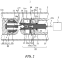
- the movable contact unit 20 includes a movable shaft 3 that extends out to the exterior of the pressure chamber 2, and the movable shaft 3 is connected to an operation mechanism 5.
- the operation mechanism 5 is attached to the pressure chamber 2.
- the operation mechanism 5 linearly reciprocates the movable contact unit 20 via the movable shaft 3, and moves the movable contact unit 20 to be apart or in contact relative to the fixed contact unit 10.
- the fixed contact unit 10 includes a fixed arcing contact 11, a fixed conductive contacts 12, a fixed contact base 13, and a fixed shield 14, all arranged concentrically to one another.
- a spring 16 is placed inside the fixed shield 14.
- the fixed contact base 13 is fixed to the pressure chamber 2.
- the fixed arcing contact 11 in a bar shape is attached to the center part of the fixed contact base 13.
- a cylindrical portion 13a that is thinner than the outer diameter of the base 13 protrudes and is formed on the tip end surface of the fixed contact base 13, and the fixed conductive contact 12 is placed so as to surround the cylindrical portion 13a.
- the plurality of fixed conductive contacts 12 is placed in the circumferential direction, and the tip end portions are bent toward the internal side.
- the fixed conductive contacts 12 are pushed by the spring 16 in the internal direction, and at the same time abuts the outer circumference of the cylindrical portion 13a of the fixed contact base 13, and thus the movement toward the internal side by the spring 16 is restricted.
- the movable contact unit 20 includes a movable contact 21, a movable contact base 22, a movable shield 23, and an operation rod 25, all arranged concentrically to one another.
- the operation rod 25 has the tip end portion connected to the movable contact 21, and the basal end portion connected to the movable shaft 3.
- the operation rod 25 moves the movable contact 21 to be apart or in contact relative to the fixed arcing contact 11 and the fixed conductive contact 12 due to the movable shaft 3 performing reciprocation movement by the operation mechanism 5.
- An arc-resistant metal 24 that has arc-resistant characteristics is firmly attached to the tip end portion of the movable contact 21.
- the arc-resistant metal 24 is formed in a ring shape so that the arc-resistant metal 15 of the fixed arcing contact 11 is in contact or moves apart relative to the inner circumference. That is, in the movable contact unit 20, the operation rod 25 and movable contact 21 are members that move in an circuit opening operation and circuit closing operation.
- the movable contact base 22 is a component that is fixed to the pressure chamber 2
- the movable shield 23 is a component that is fixed to the movable contact base 22 even in the movable contact unit 20.
- a plurality of ventilation holes 21a each extending in the lengthwise direction of the movable contact 21 is provided.
- the ventilation hole 21a is a hole that passes completely through from the end surface of the movable contact 21 to the hollow portion 25b of the operation rod 25.
- An opening of the ventilation hole 21a at the tip end portion side is arranged so as to face the end portion of the arc-resistant metal 15 of the fixed arcing contact 11.
- a holder hole 22c is opened at the center of the flange 22d of the movable contact base 22.
- the operation rod 25 is inserted in the holder hole 22c.
- a clearance 33 is formed between the inner circumference of the holder hole 22c of the movable contact base 22 and the outer circumference of the operation rod 25. This clearance 33 becomes a gap when the gas flow volume limiting portion 22e of the movable contact base 22 covers the communication hole 25c.
- the arc 40 (illustrated in FIG. 2 ) is produced between the arc-resistant metal 24 of the movable contact 21 side and the arc-resistant metal 15 of the fixed arcing contact 11 side. Since the arc 40 is in extremely high temperature, the insulating gas therearound becomes the high-temperature thermal gas, and remains between the fixed arcing contact 11 and the movable contact 21.
- the following operation is executed. That is, in the circuit opening operation, the piston 25a that is driven to the right side associated with the movement of the operation rod 25 compresses the low-temperature gas in the compression chamber 30.
- the low-temperature gas compressed in the compression chamber 30 passes through the communication hole 25c, the hollow portion 25b, and the plurality of ventilation holes 21a in sequence, and is sprayed between the fixed arcing contact 11 and the movable contact 21.
- the ventilation hole 21a can intensively spray a large amount of low-temperature gas from the compression chamber 30 to the thermal gas due to the arc 40. Accordingly, the thermal gas due to the arc 40 can be cooled efficiently, and the remaining thermal gas can be diffused all around from the space where the arc 40 is produced, and can be blown away from between the fixed arcing contact 11 and the movable contact 21.
- the thermal gas diffused along the outer circumference of the movable contact 21 by the sprayed low-temperature gas can smoothly flow toward the clearance 31a.
- the suction chamber 31 since the pressure in the suction chamber 31 decreases by the piston 25a that starts moving, the suction chamber 31 can quickly suction the thermal gas through the clearance 31a from the initial stage of the circuit opening operation.
- the gas-insulated switchgear 1 of the first embodiment since the thermal gas is removed from between the fixed arcing contact 11 and the movable contact 21, re-ignition of the fixed arcing contact 11 and the movable contact 21 hardly occurs. Accordingly, an excellent insulation performance relative to the transient recovery voltage after the current breaking can be obtained. Hence, the gas-insulated switchgear 1 can easily achieve the current breaking duty required for a switchgear for a high voltage, and reduces a load on the operation mechanism 5, contributing to a reduction of a current breaking time.
- the gas flow volume limiting portion 22e of the flange 22d of the movable contact base 22 covers at least a part of the communication hole 25c of the operation rod 25 at the end of the circuit opening operation, the cross-sectional area of the communication hole 25c in communication with the compression chamber 30 decreases. Accordingly, immediately before the end of the circuit opening operation, the flow volume of the low-temperature gas that flows toward the ventilation hole 21a from the compression chamber 30 can be reduced, and the internal pressure of the compression chamber 30 increases.
- a circuit opening operation according to the second embodiment that employs the above structure will be described through a transition from a close-circuit state illustrated in FIG. 3 to the open-circuit state illustrated in FIG. 4 .
- the detailed description will be omitted.
Landscapes
- Circuit Breakers (AREA)
- Arc-Extinguishing Devices That Are Switches (AREA)
Claims (7)
- Appareillage de commutation à isolation gazeuse (1) comprenant :une chambre de pression (2) dans laquelle un gaz isolant est rempli de manière étanche au gaz;une base de contact fixe (13) et une base de contact mobile (22) placées dans la chambre de pression (2) de manière à se faire face ;un contact d'arc fixe (11) fixé à la base de contact fixe (13);un blindage fixe (14) fixé à la base de contact fixe (13) de manière à entourer le contact d'arc fixe (11);un contact conducteur fixe (12) placé au niveau du blindage fixe (14);un contact mobile (21) placé de manière à faire face au contact conducteur fixe (12) et à être librement mobile ;un blindage mobile (23) fixé à la base de contact mobile (22) de manière à entourer le contact mobile (21) ;une tige de manoeuvre (25) qui est raccordée au contact mobile (21) et à laquelle est fixée un piston (25a) ; etun mécanisme de commande (5) qui fait effectuer un mouvement de va-et-vient à la tige de manoeuvre (25) de manière à déplacer le contact mobile (21) pour qu'il soit séparé ou en contact par rapport au contact d'arc fixe (11) et au contact conducteur fixe (12), dans lequel :à l'intérieur du blindage mobile (23), le piston (25a) de la tige de manoeuvre (25) étant une cloison de séparation, une chambre de compression (30) et une chambre d'aspiration sont formées au niveau d'un côté de base de contact mobile et au niveau du côté de contact mobile, respectivement ;caractérisé en ce quela tige de manoeuvre (25) est dotée d'une partie creuse (25b), et un trou de communication (25c) qui fait communiquer la partie creuse (25b) et la chambre de compression (30) ;le contact mobile (21) est pourvu d'un trou de ventilation (21a, 21b) qui traverse complètement depuis une surface d'extrémité du contact mobile (21) jusqu'à la partie creuse (25b) de la tige de manoeuvre (25);la chambre de compression (30) comprime le gaz isolant à l'intérieur par un mouvement du piston (25a) associé à un mouvement de la tige de manoeuvre (25) à un moment d'une opération d'ouverture de circuit et pulvérise le gaz isolant sur un arc (40) réalisé entre le contact d'arc fixe (11) et le contact mobile (21) via le trou de communication (25c), la partie creuse (25b) et le trou de ventilation (21a, 21b) ;un espace (31a, 33, 34) est ménagé entre une circonférence externe du contact mobile (21) et une circonférence interne du blindage mobile (23) et la chambre d'aspiration réduit une pression interne en élargissant un espace interne (22 a) par un mouvement du piston(25a) associé à un mouvement de la tige de manoeuvre (25) au moment de l'opération d'ouverture de circuit et aspire le gaz isolant à haute température chauffé par l'arc (40) dans l'espace interne (22a) à travers l'espace (31a, 33, 34);un premier trou d'aspiration (22b) pour aspirer le gaz isolant dans la chambre de compression (30) au moment de l'opération de fermeture de circuit est formé dans une surface d'extrémité de la base de contact mobile (22) faisant face à la chambre de compression (30) ; etune vanne (32) qui bloque le premier trou d'aspiration (22b) au moment de l'opération d'ouverture du circuit et qui ouvre le premier trou d'aspiration (22b) est fixé au premier trou d'aspiration (22b) lors de l'opération de fermeture de circuit.
- Appareillage de commutation à isolation gazeuse (1) selon la revendication 1, dans lequel :un deuxième trou d'aspiration (25d) qui fait communiquer la chambre d'aspiration et la chambre de compression (30), et qui doit aspirer le gaz isolant dans la chambre d'aspiration à l'intérieur de la chambre de compression (30) au moment de l'opération de fermeture de circuit est formé dans le piston (25a); etune vanne (32) qui bouche le deuxième trou d'aspiration (25d) au moment de l'opération d'ouverture du circuit et qui ouvre le deuxième trou d'aspiration (25d) au moment de l'opération de fermeture de circuit est fixé au deuxième trou d'aspiration (25d).
- Appareillage de commutation à isolation gazeuse (1) selon la revendication 5, 1 ou 2, dans lequel la vanne (32) est placée dans la chambre de compression (30).
- Appareillage de commutation à isolation gazeuse (1) selon une quelconque des revendications 1 à 3, comprenant en outre une partie de positionnement de vanne qui positionne la vanne (32) à une fin de l'opération de fermeture de circuit.
- Appareillage de commutation à isolation gazeuse (1) selon une quelconque des revendications 1 à 4, dans lequel l'orifice de ventilation (21a, 21b) est formé de manière à augmenter la surface transversale du canal d'écoulement pour le gaz isolant depuis une partie raccordée à la partie creuse (25b) de la tige de manoeuvre (25) vers une surface d'extrémité du contact mobile (21).
- Appareillage de commutation à isolation gazeuse (1) selon une des revendications 1 à 5, dans laquelle une partie de limitation du volume du flux de gaz (22e) qui recouvre au moins une partie du trou de communication (25c) à une fin de l'opération d'ouverture de circuit est disposée au niveau d'une surface d'extrémité de la base de contact mobile (22).
- Appareillage de commutation à isolation gazeuse(1) selon une quelconque des revendications 1 à 6, comprenant en outre une garniture coulissante (27, 28) placée de manière à entrer en contact avec une circonférence intérieure de la base de contact mobile (22) et une circonférence extérieure de la tige de manoeuvre (25),
dans lequel la garniture coulissante (27, 28) est configurée pour bloquer une partie du trou de communication (25c) de la tige de manoeuvre (25) à la fin de l'opération d'ouverture de circuit.
Applications Claiming Priority (1)
| Application Number | Priority Date | Filing Date | Title |
|---|---|---|---|
| PCT/JP2016/087587 WO2018109931A1 (fr) | 2016-12-16 | 2016-12-16 | Dispositif de commutation à isolation gazeuse |
Publications (3)
| Publication Number | Publication Date |
|---|---|
| EP3561840A1 EP3561840A1 (fr) | 2019-10-30 |
| EP3561840A4 EP3561840A4 (fr) | 2020-08-19 |
| EP3561840B1 true EP3561840B1 (fr) | 2024-07-10 |
Family
ID=62558270
Family Applications (1)
| Application Number | Title | Priority Date | Filing Date |
|---|---|---|---|
| EP16923924.1A Active EP3561840B1 (fr) | 2016-12-16 | 2016-12-16 | Dispositif de commutation à isolation gazeuse |
Country Status (4)
| Country | Link |
|---|---|
| EP (1) | EP3561840B1 (fr) |
| JP (1) | JP6823082B2 (fr) |
| CN (1) | CN110088866B (fr) |
| WO (1) | WO2018109931A1 (fr) |
Families Citing this family (2)
| Publication number | Priority date | Publication date | Assignee | Title |
|---|---|---|---|---|
| WO2021138366A1 (fr) * | 2019-12-31 | 2021-07-08 | Southern States Llc | Commutateur de puissance électrique haute tension avec électrodes d'arc de carbone et gaz diélectrique de dioxyde de carbone |
| KR102877948B1 (ko) * | 2021-12-27 | 2025-10-28 | 엘에스일렉트릭(주) | 가스절연 개폐장치 |
Family Cites Families (23)
| Publication number | Priority date | Publication date | Assignee | Title |
|---|---|---|---|---|
| JPS5553824A (en) | 1978-10-17 | 1980-04-19 | Mitsubishi Electric Corp | Gas switch |
| JPS58100326A (ja) * | 1981-12-10 | 1983-06-15 | 株式会社東芝 | パツフア形ガスしや断器 |
| JPS6114444A (ja) | 1984-06-30 | 1986-01-22 | Nec Home Electronics Ltd | 空燃比制御方法 |
| JPH0214741U (fr) * | 1988-07-15 | 1990-01-30 | ||
| JP2512502Y2 (ja) * | 1988-12-02 | 1996-10-02 | 株式会社高岳製作所 | ガス絶縁断路器 |
| JPH03116638U (fr) * | 1990-03-14 | 1991-12-03 | ||
| FR2680044B1 (fr) | 1991-08-02 | 1995-01-20 | Alsthom Gec | Disjoncteur a moyenne ou haute tension a contacts d'arc en bout. |
| JPH0553094U (ja) * | 1991-12-24 | 1993-07-13 | 株式会社東芝 | ガス絶縁接地開閉器 |
| DE19517615A1 (de) | 1995-05-13 | 1996-11-14 | Abb Research Ltd | Leistungsschalter |
| JP2002075148A (ja) | 2000-08-31 | 2002-03-15 | Hitachi Ltd | パッファ形ガス遮断器 |
| JP2008112633A (ja) | 2006-10-30 | 2008-05-15 | Mitsubishi Electric Corp | ガス遮断器 |
| EP2278604B1 (fr) * | 2009-07-21 | 2012-03-14 | ABB Technology AG | Commutateur haute tension |
| WO2012093507A1 (fr) * | 2011-01-07 | 2012-07-12 | 三菱電機株式会社 | Appareil de commutation |
| JP5516568B2 (ja) * | 2011-12-28 | 2014-06-11 | 株式会社日立製作所 | パッファ形ガス遮断器 |
| JP6157824B2 (ja) | 2012-09-28 | 2017-07-05 | 株式会社東芝 | ガス遮断器 |
| TW201442051A (zh) * | 2013-03-08 | 2014-11-01 | Hitachi Ltd | 氣體斷路器 |
| JP2015043656A (ja) | 2013-08-26 | 2015-03-05 | 株式会社東芝 | 開閉器 |
| JP6289856B2 (ja) | 2013-10-16 | 2018-03-07 | 株式会社東芝 | ガス遮断器 |
| JP6382543B2 (ja) | 2014-03-24 | 2018-08-29 | 株式会社東芝 | ガス遮断器 |
| JP6320106B2 (ja) | 2014-03-25 | 2018-05-09 | 株式会社東芝 | ガス遮断器 |
| CN107077988B (zh) | 2014-06-02 | 2019-07-16 | Abb瑞士股份有限公司 | 高电压压气式断路器及具有这种压气式断路器的断路器单元 |
| KR101632978B1 (ko) * | 2014-06-26 | 2016-06-24 | 현대중공업 주식회사 | 가스절연 차단기 |
| CN105023800B (zh) * | 2015-07-08 | 2018-01-26 | 平高集团有限公司 | 双动灭弧室、断路器和气体绝缘金属封闭开关设备 |
-
2016
- 2016-12-16 WO PCT/JP2016/087587 patent/WO2018109931A1/fr not_active Ceased
- 2016-12-16 CN CN201680091563.3A patent/CN110088866B/zh active Active
- 2016-12-16 EP EP16923924.1A patent/EP3561840B1/fr active Active
- 2016-12-16 JP JP2018556149A patent/JP6823082B2/ja active Active
Also Published As
| Publication number | Publication date |
|---|---|
| EP3561840A1 (fr) | 2019-10-30 |
| CN110088866B (zh) | 2021-11-19 |
| WO2018109931A1 (fr) | 2018-06-21 |
| JPWO2018109931A1 (ja) | 2019-10-24 |
| CN110088866A (zh) | 2019-08-02 |
| JP6823082B2 (ja) | 2021-02-03 |
| EP3561840A4 (fr) | 2020-08-19 |
Similar Documents
| Publication | Publication Date | Title |
|---|---|---|
| EP3284098B2 (fr) | Dispositif permettant de couper seulement des courants autres que de court-circuit, en particulier sectionneur ou interrupteur de mise à la terre | |
| CN112074923B (zh) | 具有屏蔽装置的气体绝缘中压开关 | |
| US10354821B2 (en) | Gas circuit breaker | |
| KR101919125B1 (ko) | 고압 배전기의 가스절연 개폐장치 | |
| US8766131B2 (en) | Gas-insulated high-voltage switch | |
| EP3561840B1 (fr) | Dispositif de commutation à isolation gazeuse | |
| CN102034640A (zh) | 具有并联额定电流路径的功率开关 | |
| WO2019122353A1 (fr) | Disjoncteur haute ou moyenne tension à isolation gazeuse | |
| US11062862B2 (en) | Gas-insulated high or medium voltage circuit breaker | |
| EP4141901B1 (fr) | Disjoncteur métallique fermé | |
| EP4476753B1 (fr) | Sectionneur de terre rapide permettant de couper des courants autres que de court-circuit | |
| EP4117006B1 (fr) | Disjoncteur haute ou moyenne tension isolé au gaz | |
| EP2682974A1 (fr) | Ensemble de tige poussoir destiné à un disjoncteur sous vide à moyenne tension | |
| EP4125108B1 (fr) | Disjoncteur haute ou moyenne tension isolé au gaz | |
| JP2015082368A (ja) | ガス遮断器 | |
| EP4345858A1 (fr) | Commutateur, commutateur coupe-charge et appareillage de commutation | |
| JP6736345B2 (ja) | ガス遮断器 | |
| JP2017034921A (ja) | 開閉装置 | |
| JP2020155302A (ja) | ガス遮断器 | |
| JP2013171803A (ja) | ガス遮断器 | |
| CN112673445A (zh) | 气体绝缘开关 | |
| JP2017068997A (ja) | ガス遮断器 |
Legal Events
| Date | Code | Title | Description |
|---|---|---|---|
| STAA | Information on the status of an ep patent application or granted ep patent |
Free format text: STATUS: THE INTERNATIONAL PUBLICATION HAS BEEN MADE |
|
| PUAI | Public reference made under article 153(3) epc to a published international application that has entered the european phase |
Free format text: ORIGINAL CODE: 0009012 |
|
| STAA | Information on the status of an ep patent application or granted ep patent |
Free format text: STATUS: REQUEST FOR EXAMINATION WAS MADE |
|
| 17P | Request for examination filed |
Effective date: 20190715 |
|
| AK | Designated contracting states |
Kind code of ref document: A1 Designated state(s): AL AT BE BG CH CY CZ DE DK EE ES FI FR GB GR HR HU IE IS IT LI LT LU LV MC MK MT NL NO PL PT RO RS SE SI SK SM TR |
|
| AX | Request for extension of the european patent |
Extension state: BA ME |
|
| DAV | Request for validation of the european patent (deleted) | ||
| DAX | Request for extension of the european patent (deleted) | ||
| A4 | Supplementary search report drawn up and despatched |
Effective date: 20200722 |
|
| RIC1 | Information provided on ipc code assigned before grant |
Ipc: H01H 33/91 20060101ALI20200716BHEP Ipc: H01H 33/90 20060101ALI20200716BHEP Ipc: H01H 33/88 20060101ALI20200716BHEP Ipc: H01H 33/04 20060101AFI20200716BHEP |
|
| STAA | Information on the status of an ep patent application or granted ep patent |
Free format text: STATUS: EXAMINATION IS IN PROGRESS |
|
| 17Q | First examination report despatched |
Effective date: 20221025 |
|
| GRAP | Despatch of communication of intention to grant a patent |
Free format text: ORIGINAL CODE: EPIDOSNIGR1 |
|
| STAA | Information on the status of an ep patent application or granted ep patent |
Free format text: STATUS: GRANT OF PATENT IS INTENDED |
|
| INTG | Intention to grant announced |
Effective date: 20240318 |
|
| GRAS | Grant fee paid |
Free format text: ORIGINAL CODE: EPIDOSNIGR3 |
|
| GRAA | (expected) grant |
Free format text: ORIGINAL CODE: 0009210 |
|
| STAA | Information on the status of an ep patent application or granted ep patent |
Free format text: STATUS: THE PATENT HAS BEEN GRANTED |
|
| AK | Designated contracting states |
Kind code of ref document: B1 Designated state(s): AL AT BE BG CH CY CZ DE DK EE ES FI FR GB GR HR HU IE IS IT LI LT LU LV MC MK MT NL NO PL PT RO RS SE SI SK SM TR |
|
| REG | Reference to a national code |
Ref country code: CH Ref legal event code: EP |
|
| REG | Reference to a national code |
Ref country code: DE Ref legal event code: R096 Ref document number: 602016088392 Country of ref document: DE |
|
| REG | Reference to a national code |
Ref country code: SE Ref legal event code: TRGR |
|
| REG | Reference to a national code |
Ref country code: LT Ref legal event code: MG9D |
|
| REG | Reference to a national code |
Ref country code: NL Ref legal event code: MP Effective date: 20240710 |
|
| PG25 | Lapsed in a contracting state [announced via postgrant information from national office to epo] |
Ref country code: PT Free format text: LAPSE BECAUSE OF FAILURE TO SUBMIT A TRANSLATION OF THE DESCRIPTION OR TO PAY THE FEE WITHIN THE PRESCRIBED TIME-LIMIT Effective date: 20241111 |
|
| REG | Reference to a national code |
Ref country code: AT Ref legal event code: MK05 Ref document number: 1702804 Country of ref document: AT Kind code of ref document: T Effective date: 20240710 |
|
| PG25 | Lapsed in a contracting state [announced via postgrant information from national office to epo] |
Ref country code: NL Free format text: LAPSE BECAUSE OF FAILURE TO SUBMIT A TRANSLATION OF THE DESCRIPTION OR TO PAY THE FEE WITHIN THE PRESCRIBED TIME-LIMIT Effective date: 20240710 |
|
| PG25 | Lapsed in a contracting state [announced via postgrant information from national office to epo] |
Ref country code: PT Free format text: LAPSE BECAUSE OF FAILURE TO SUBMIT A TRANSLATION OF THE DESCRIPTION OR TO PAY THE FEE WITHIN THE PRESCRIBED TIME-LIMIT Effective date: 20241111 Ref country code: NL Free format text: LAPSE BECAUSE OF FAILURE TO SUBMIT A TRANSLATION OF THE DESCRIPTION OR TO PAY THE FEE WITHIN THE PRESCRIBED TIME-LIMIT Effective date: 20240710 |
|
| PG25 | Lapsed in a contracting state [announced via postgrant information from national office to epo] |
Ref country code: NO Free format text: LAPSE BECAUSE OF FAILURE TO SUBMIT A TRANSLATION OF THE DESCRIPTION OR TO PAY THE FEE WITHIN THE PRESCRIBED TIME-LIMIT Effective date: 20241010 |
|
| PG25 | Lapsed in a contracting state [announced via postgrant information from national office to epo] |
Ref country code: PL Free format text: LAPSE BECAUSE OF FAILURE TO SUBMIT A TRANSLATION OF THE DESCRIPTION OR TO PAY THE FEE WITHIN THE PRESCRIBED TIME-LIMIT Effective date: 20240710 Ref country code: GR Free format text: LAPSE BECAUSE OF FAILURE TO SUBMIT A TRANSLATION OF THE DESCRIPTION OR TO PAY THE FEE WITHIN THE PRESCRIBED TIME-LIMIT Effective date: 20241011 Ref country code: FI Free format text: LAPSE BECAUSE OF FAILURE TO SUBMIT A TRANSLATION OF THE DESCRIPTION OR TO PAY THE FEE WITHIN THE PRESCRIBED TIME-LIMIT Effective date: 20240710 |
|
| PG25 | Lapsed in a contracting state [announced via postgrant information from national office to epo] |
Ref country code: BG Free format text: LAPSE BECAUSE OF FAILURE TO SUBMIT A TRANSLATION OF THE DESCRIPTION OR TO PAY THE FEE WITHIN THE PRESCRIBED TIME-LIMIT Effective date: 20240710 |
|
| PG25 | Lapsed in a contracting state [announced via postgrant information from national office to epo] |
Ref country code: LV Free format text: LAPSE BECAUSE OF FAILURE TO SUBMIT A TRANSLATION OF THE DESCRIPTION OR TO PAY THE FEE WITHIN THE PRESCRIBED TIME-LIMIT Effective date: 20240710 |
|
| PG25 | Lapsed in a contracting state [announced via postgrant information from national office to epo] |
Ref country code: IS Free format text: LAPSE BECAUSE OF FAILURE TO SUBMIT A TRANSLATION OF THE DESCRIPTION OR TO PAY THE FEE WITHIN THE PRESCRIBED TIME-LIMIT Effective date: 20241110 Ref country code: AT Free format text: LAPSE BECAUSE OF FAILURE TO SUBMIT A TRANSLATION OF THE DESCRIPTION OR TO PAY THE FEE WITHIN THE PRESCRIBED TIME-LIMIT Effective date: 20240710 |
|
| PG25 | Lapsed in a contracting state [announced via postgrant information from national office to epo] |
Ref country code: HR Free format text: LAPSE BECAUSE OF FAILURE TO SUBMIT A TRANSLATION OF THE DESCRIPTION OR TO PAY THE FEE WITHIN THE PRESCRIBED TIME-LIMIT Effective date: 20240710 |
|
| PG25 | Lapsed in a contracting state [announced via postgrant information from national office to epo] |
Ref country code: ES Free format text: LAPSE BECAUSE OF FAILURE TO SUBMIT A TRANSLATION OF THE DESCRIPTION OR TO PAY THE FEE WITHIN THE PRESCRIBED TIME-LIMIT Effective date: 20240710 Ref country code: RS Free format text: LAPSE BECAUSE OF FAILURE TO SUBMIT A TRANSLATION OF THE DESCRIPTION OR TO PAY THE FEE WITHIN THE PRESCRIBED TIME-LIMIT Effective date: 20241010 |
|
| PG25 | Lapsed in a contracting state [announced via postgrant information from national office to epo] |
Ref country code: RS Free format text: LAPSE BECAUSE OF FAILURE TO SUBMIT A TRANSLATION OF THE DESCRIPTION OR TO PAY THE FEE WITHIN THE PRESCRIBED TIME-LIMIT Effective date: 20241010 Ref country code: PL Free format text: LAPSE BECAUSE OF FAILURE TO SUBMIT A TRANSLATION OF THE DESCRIPTION OR TO PAY THE FEE WITHIN THE PRESCRIBED TIME-LIMIT Effective date: 20240710 Ref country code: NO Free format text: LAPSE BECAUSE OF FAILURE TO SUBMIT A TRANSLATION OF THE DESCRIPTION OR TO PAY THE FEE WITHIN THE PRESCRIBED TIME-LIMIT Effective date: 20241010 Ref country code: LV Free format text: LAPSE BECAUSE OF FAILURE TO SUBMIT A TRANSLATION OF THE DESCRIPTION OR TO PAY THE FEE WITHIN THE PRESCRIBED TIME-LIMIT Effective date: 20240710 Ref country code: IS Free format text: LAPSE BECAUSE OF FAILURE TO SUBMIT A TRANSLATION OF THE DESCRIPTION OR TO PAY THE FEE WITHIN THE PRESCRIBED TIME-LIMIT Effective date: 20241110 Ref country code: HR Free format text: LAPSE BECAUSE OF FAILURE TO SUBMIT A TRANSLATION OF THE DESCRIPTION OR TO PAY THE FEE WITHIN THE PRESCRIBED TIME-LIMIT Effective date: 20240710 Ref country code: GR Free format text: LAPSE BECAUSE OF FAILURE TO SUBMIT A TRANSLATION OF THE DESCRIPTION OR TO PAY THE FEE WITHIN THE PRESCRIBED TIME-LIMIT Effective date: 20241011 Ref country code: FI Free format text: LAPSE BECAUSE OF FAILURE TO SUBMIT A TRANSLATION OF THE DESCRIPTION OR TO PAY THE FEE WITHIN THE PRESCRIBED TIME-LIMIT Effective date: 20240710 Ref country code: ES Free format text: LAPSE BECAUSE OF FAILURE TO SUBMIT A TRANSLATION OF THE DESCRIPTION OR TO PAY THE FEE WITHIN THE PRESCRIBED TIME-LIMIT Effective date: 20240710 Ref country code: BG Free format text: LAPSE BECAUSE OF FAILURE TO SUBMIT A TRANSLATION OF THE DESCRIPTION OR TO PAY THE FEE WITHIN THE PRESCRIBED TIME-LIMIT Effective date: 20240710 Ref country code: AT Free format text: LAPSE BECAUSE OF FAILURE TO SUBMIT A TRANSLATION OF THE DESCRIPTION OR TO PAY THE FEE WITHIN THE PRESCRIBED TIME-LIMIT Effective date: 20240710 |
|
| REG | Reference to a national code |
Ref country code: DE Ref legal event code: R097 Ref document number: 602016088392 Country of ref document: DE |
|
| PG25 | Lapsed in a contracting state [announced via postgrant information from national office to epo] |
Ref country code: SM Free format text: LAPSE BECAUSE OF FAILURE TO SUBMIT A TRANSLATION OF THE DESCRIPTION OR TO PAY THE FEE WITHIN THE PRESCRIBED TIME-LIMIT Effective date: 20240710 Ref country code: RO Free format text: LAPSE BECAUSE OF FAILURE TO SUBMIT A TRANSLATION OF THE DESCRIPTION OR TO PAY THE FEE WITHIN THE PRESCRIBED TIME-LIMIT Effective date: 20240710 Ref country code: DK Free format text: LAPSE BECAUSE OF FAILURE TO SUBMIT A TRANSLATION OF THE DESCRIPTION OR TO PAY THE FEE WITHIN THE PRESCRIBED TIME-LIMIT Effective date: 20240710 |
|
| PG25 | Lapsed in a contracting state [announced via postgrant information from national office to epo] |
Ref country code: EE Free format text: LAPSE BECAUSE OF FAILURE TO SUBMIT A TRANSLATION OF THE DESCRIPTION OR TO PAY THE FEE WITHIN THE PRESCRIBED TIME-LIMIT Effective date: 20240710 |
|
| PG25 | Lapsed in a contracting state [announced via postgrant information from national office to epo] |
Ref country code: CZ Free format text: LAPSE BECAUSE OF FAILURE TO SUBMIT A TRANSLATION OF THE DESCRIPTION OR TO PAY THE FEE WITHIN THE PRESCRIBED TIME-LIMIT Effective date: 20240710 |
|
| PG25 | Lapsed in a contracting state [announced via postgrant information from national office to epo] |
Ref country code: IT Free format text: LAPSE BECAUSE OF FAILURE TO SUBMIT A TRANSLATION OF THE DESCRIPTION OR TO PAY THE FEE WITHIN THE PRESCRIBED TIME-LIMIT Effective date: 20240710 Ref country code: SK Free format text: LAPSE BECAUSE OF FAILURE TO SUBMIT A TRANSLATION OF THE DESCRIPTION OR TO PAY THE FEE WITHIN THE PRESCRIBED TIME-LIMIT Effective date: 20240710 |
|
| PLBE | No opposition filed within time limit |
Free format text: ORIGINAL CODE: 0009261 |
|
| STAA | Information on the status of an ep patent application or granted ep patent |
Free format text: STATUS: NO OPPOSITION FILED WITHIN TIME LIMIT |
|
| 26N | No opposition filed |
Effective date: 20250411 |
|
| PG25 | Lapsed in a contracting state [announced via postgrant information from national office to epo] |
Ref country code: MC Free format text: LAPSE BECAUSE OF FAILURE TO SUBMIT A TRANSLATION OF THE DESCRIPTION OR TO PAY THE FEE WITHIN THE PRESCRIBED TIME-LIMIT Effective date: 20240710 |
|
| REG | Reference to a national code |
Ref country code: CH Ref legal event code: PL |
|
| PG25 | Lapsed in a contracting state [announced via postgrant information from national office to epo] |
Ref country code: LU Free format text: LAPSE BECAUSE OF NON-PAYMENT OF DUE FEES Effective date: 20241216 |
|
| REG | Reference to a national code |
Ref country code: BE Ref legal event code: MM Effective date: 20241231 |
|
| PG25 | Lapsed in a contracting state [announced via postgrant information from national office to epo] |
Ref country code: BE Free format text: LAPSE BECAUSE OF NON-PAYMENT OF DUE FEES Effective date: 20241231 |
|
| PG25 | Lapsed in a contracting state [announced via postgrant information from national office to epo] |
Ref country code: FR Free format text: LAPSE BECAUSE OF NON-PAYMENT OF DUE FEES Effective date: 20241231 |
|
| PG25 | Lapsed in a contracting state [announced via postgrant information from national office to epo] |
Ref country code: CH Free format text: LAPSE BECAUSE OF NON-PAYMENT OF DUE FEES Effective date: 20241231 |
|
| PG25 | Lapsed in a contracting state [announced via postgrant information from national office to epo] |
Ref country code: IE Free format text: LAPSE BECAUSE OF NON-PAYMENT OF DUE FEES Effective date: 20241216 |
|
| PGFP | Annual fee paid to national office [announced via postgrant information from national office to epo] |
Ref country code: DE Payment date: 20250930 Year of fee payment: 10 |
|
| PGFP | Annual fee paid to national office [announced via postgrant information from national office to epo] |
Ref country code: GB Payment date: 20251001 Year of fee payment: 10 |
|
| PGFP | Annual fee paid to national office [announced via postgrant information from national office to epo] |
Ref country code: SE Payment date: 20251001 Year of fee payment: 10 |