EP3562005A1 - Mesure de température pour générateur électrique - Google Patents
Mesure de température pour générateur électrique Download PDFInfo
- Publication number
- EP3562005A1 EP3562005A1 EP18169418.3A EP18169418A EP3562005A1 EP 3562005 A1 EP3562005 A1 EP 3562005A1 EP 18169418 A EP18169418 A EP 18169418A EP 3562005 A1 EP3562005 A1 EP 3562005A1
- Authority
- EP
- European Patent Office
- Prior art keywords
- axial end
- electric generator
- magnet
- temperature
- rotor
- Prior art date
- Legal status (The legal status is an assumption and is not a legal conclusion. Google has not performed a legal analysis and makes no representation as to the accuracy of the status listed.)
- Withdrawn
Links
Images

Classifications
-
- H—ELECTRICITY
- H02—GENERATION; CONVERSION OR DISTRIBUTION OF ELECTRIC POWER
- H02K—DYNAMO-ELECTRIC MACHINES
- H02K1/00—Details of the magnetic circuit
- H02K1/06—Details of the magnetic circuit characterised by the shape, form or construction
- H02K1/22—Rotating parts of the magnetic circuit
- H02K1/27—Rotor cores with permanent magnets
- H02K1/2786—Outer rotors
- H02K1/2787—Outer rotors the magnetisation axis of the magnets being perpendicular to the rotor axis
- H02K1/2789—Outer rotors the magnetisation axis of the magnets being perpendicular to the rotor axis the rotor consisting of two or more circumferentially positioned magnets
- H02K1/2791—Surface mounted magnets; Inset magnets
-
- H—ELECTRICITY
- H02—GENERATION; CONVERSION OR DISTRIBUTION OF ELECTRIC POWER
- H02K—DYNAMO-ELECTRIC MACHINES
- H02K11/00—Structural association of dynamo-electric machines with electric components or with devices for shielding, monitoring or protection
- H02K11/20—Structural association of dynamo-electric machines with electric components or with devices for shielding, monitoring or protection for measuring, monitoring, testing, protecting or switching
- H02K11/25—Devices for sensing temperature, or actuated thereby
-
- F—MECHANICAL ENGINEERING; LIGHTING; HEATING; WEAPONS; BLASTING
- F03—MACHINES OR ENGINES FOR LIQUIDS; WIND, SPRING, OR WEIGHT MOTORS; PRODUCING MECHANICAL POWER OR A REACTIVE PROPULSIVE THRUST, NOT OTHERWISE PROVIDED FOR
- F03D—WIND MOTORS
- F03D9/00—Adaptations of wind motors for special use; Combinations of wind motors with apparatus driven thereby; Wind motors specially adapted for installation in particular locations
- F03D9/20—Wind motors characterised by the driven apparatus
- F03D9/25—Wind motors characterised by the driven apparatus the apparatus being an electrical generator
-
- F—MECHANICAL ENGINEERING; LIGHTING; HEATING; WEAPONS; BLASTING
- F03—MACHINES OR ENGINES FOR LIQUIDS; WIND, SPRING, OR WEIGHT MOTORS; PRODUCING MECHANICAL POWER OR A REACTIVE PROPULSIVE THRUST, NOT OTHERWISE PROVIDED FOR
- F03D—WIND MOTORS
- F03D17/00—Monitoring or testing of wind motors, e.g. diagnostics
-
- F—MECHANICAL ENGINEERING; LIGHTING; HEATING; WEAPONS; BLASTING
- F05—INDEXING SCHEMES RELATING TO ENGINES OR PUMPS IN VARIOUS SUBCLASSES OF CLASSES F01-F04
- F05B—INDEXING SCHEME RELATING TO WIND, SPRING, WEIGHT, INERTIA OR LIKE MOTORS, TO MACHINES OR ENGINES FOR LIQUIDS COVERED BY SUBCLASSES F03B, F03D AND F03G
- F05B2270/00—Control
- F05B2270/30—Control parameters, e.g. input parameters
- F05B2270/303—Temperature
-
- Y—GENERAL TAGGING OF NEW TECHNOLOGICAL DEVELOPMENTS; GENERAL TAGGING OF CROSS-SECTIONAL TECHNOLOGIES SPANNING OVER SEVERAL SECTIONS OF THE IPC; TECHNICAL SUBJECTS COVERED BY FORMER USPC CROSS-REFERENCE ART COLLECTIONS [XRACs] AND DIGESTS
- Y02—TECHNOLOGIES OR APPLICATIONS FOR MITIGATION OR ADAPTATION AGAINST CLIMATE CHANGE
- Y02E—REDUCTION OF GREENHOUSE GAS [GHG] EMISSIONS, RELATED TO ENERGY GENERATION, TRANSMISSION OR DISTRIBUTION
- Y02E10/00—Energy generation through renewable energy sources
- Y02E10/70—Wind energy
- Y02E10/72—Wind turbines with rotation axis in wind direction
Definitions
- the present invention relates to a device for measuring the temperature in an electric generator.
- the present invention further relates to a method for operating an electric generator.
- the present invention applies to electric generators included in wind turbines.
- Electric generators of the kind above and methods for operating them are generally known. In particular, it is known to control that predefined threshold temperatures are not reached.
- cooling air flows in the air gap between the stator and the rotor.
- the air enters at its lowest temperature at the axial entrance of the air gap, then the more heat it collects, the warmer it becomes. Additionally, the further the air travels axially in the air gap, the lower is the flow rate, as air exits the air ducts radially towards the cavity in the center of the stator.
- the temperature of the permanent magnets along the rotational axis of the electrical generator reaches the highest values at the center and lowest at both entrances of the air gap.
- the temperature of magnets is normally measured only in one location, i.e. which is at the axial entrance of the air gap.
- the magnet temperature at the center of the generator is estimated by adding a constant value to the temperature measured on the magnets at the air gap entrance.
- the sum of the measured value and the constant is compared with a threshold safe value which has not to be reached. Whenever this threshold value is reached by the above defined sum, the turbine starts de-rating to keep temperatures below dangerous or undesired values.
- the difference between the temperature in the axial center of the magnets and the one measured at the axial air gap entrance is not constant but depends on the power output and on the wind speed.
- a maximum value which is estimated for such difference is chosen as the constant to be added to the temperature measured on the magnets at the air gap entrance.
- Such choice is obviously conservative, but it may be for some working conditions, e.g. the turbines having two converters of which one is not active, unnecessarily limiting for the power output.
- an electric generator comprising:
- the above described electric generator may be advantageously integrated in a wind turbine, in particular a wind turbine having at least two electric power converters.
- a method for operating an electric generator for a wind turbine comprising:
- the method comprises the steps of:
- the method is activated when only one of the two electrical power converters is in operation, to avoid eddy current losses arising excessively in the generator rotor.
- the temperature is directly measured by a temperature sensor installed in a measuring position intermediate between the first axial end and the second axial end of the stator.
- the exact temperature of the magnet(s) will allow de-rating the turbine based on the real temperature of the magnet(s), thus increasing the power output of the turbine, with respect to the above described solutions of the prior art.
- the rotor includes a plurality of magnets disposed in a row between the first axial end and a second axial end, said temperature sensor being disposed in the measuring position for measuring the temperature in an intermediate magnet of the plurality of magnets.
- the temperature sensor may of the contactless type and fixed to the stator, facing the portion of the magnet, whose temperature is to be measured.
- the temperature sensor may at least partially extend in the air gap comprised between the stator and the rotor, without contacting the rotor.
- the temperature sensor may be of the infrared type.
- the present invention allows measuring the temperature of the magnets in accessible an area which is difficult to access, through contactless infrared sensors.
- the at least one magnet comprises an exterior surface at the measuring position, the emissivity of the exterior surface allowing the measurement of the temperature of the at least one magnet by the temperature sensor.
- the at least one magnet may comprise a covering on the exterior surface providing the desired emissivity.
- the exterior surface of the magnet or portion of magnet, whose temperature is to be measured provides an emissivity, which allows a correct temperature measurement, in contrast with the surface of the magnets or portion of magnet, whose temperatures are not of interest and consequently can be made of reflective material (i.e. stainless steel).
- FIG. 1 shows a wind turbine 1 according to the invention.
- the wind turbine 1 comprises a tower 2, which is mounted on a non-depicted fundament.
- a nacelle 3 is arranged on top of the tower 2.
- the wind turbine 1 further comprises a wind rotor 5 having two, three or more blades 4 (in the perspective of Figure 1 only two blades 4 are visible).
- the wind rotor 5 is rotatable around a rotational axis Y.
- the terms axial, radial and circumferential in the following are made with reference to the rotational axis Y.
- the blades 4 extend radially with respect to the rotational axis Y.
- the wind turbine 1 comprises an electric generator 11 connected to two electric power converters 31, 32.
- the wind rotor 5 is rotationally coupled with the electric generator 11 by means of a rotatable main shaft 9. According to other possible embodiments of the present invention (not represented in the attached figures), the wind rotor 5 is rotationally coupled directly with the electric generator 11 (direct-drive generator configuration).
- a schematically depicted bearing assembly 8 is provided in order to hold in place the rotor 5.
- the rotatable main shaft 9 extends along the rotational axis Y.
- the electric generator 11 includes a stator 20 and a rotor 30.
- the rotor 30 is radially external to the stator 20 and is rotatable with respect to the stator 30 about the rotational axis Y.
- the rotor is radially internal to the stator 11.
- the rotor and the stator are separated by an air gap 25.
- the present invention can be applied to an electric generator, which is not comprised in a wind turbine.
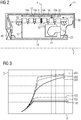
- FIG. 2 shows a schematic axial section of the electric generator 11. With respect to the rotational axis Y, the stator 20 extends:
- Figure 3 shows a graph illustrating the improvements in power output performances of the present invention, compared to the prior art.
- the abscissa X represents the wind speed
- the ordinate Z the power output of the electric generator 11 of the wind turbine.
- Curves 101, 102, 103 are obtained with a prior art method of temperature estimation in the permanent magnet which comprises the steps of:
Landscapes
- Engineering & Computer Science (AREA)
- Power Engineering (AREA)
- Life Sciences & Earth Sciences (AREA)
- Sustainable Development (AREA)
- Sustainable Energy (AREA)
- Chemical & Material Sciences (AREA)
- Combustion & Propulsion (AREA)
- Mechanical Engineering (AREA)
- General Engineering & Computer Science (AREA)
- Microelectronics & Electronic Packaging (AREA)
- Wind Motors (AREA)
Priority Applications (1)
| Application Number | Priority Date | Filing Date | Title |
|---|---|---|---|
| EP18169418.3A EP3562005A1 (fr) | 2018-04-26 | 2018-04-26 | Mesure de température pour générateur électrique |
Applications Claiming Priority (1)
| Application Number | Priority Date | Filing Date | Title |
|---|---|---|---|
| EP18169418.3A EP3562005A1 (fr) | 2018-04-26 | 2018-04-26 | Mesure de température pour générateur électrique |
Publications (1)
| Publication Number | Publication Date |
|---|---|
| EP3562005A1 true EP3562005A1 (fr) | 2019-10-30 |
Family
ID=62067441
Family Applications (1)
| Application Number | Title | Priority Date | Filing Date |
|---|---|---|---|
| EP18169418.3A Withdrawn EP3562005A1 (fr) | 2018-04-26 | 2018-04-26 | Mesure de température pour générateur électrique |
Country Status (1)
| Country | Link |
|---|---|
| EP (1) | EP3562005A1 (fr) |
Citations (10)
| Publication number | Priority date | Publication date | Assignee | Title |
|---|---|---|---|---|
| JPS5599033A (en) * | 1979-01-24 | 1980-07-28 | Mitsubishi Electric Corp | Measuring device for temperature |
| US20050029975A1 (en) * | 2003-08-05 | 2005-02-10 | Kendro Laboratory Products, Lp | Motor temperature sensor system and method to determine motor performance |
| WO2010006631A1 (fr) * | 2008-07-16 | 2010-01-21 | Siemens Aktiengesellschaft | Agencement avec une machine électrique et procédé de fonctionnement d'une machine électrique |
| US20110133586A1 (en) * | 2009-12-08 | 2011-06-09 | Henrik Stiesdal | Arrangement to Compensate a Non-Uniform Air Gap of an Electric Machine |
| US20110133461A1 (en) * | 2011-01-17 | 2011-06-09 | Vestas Wind Systems A/S | Operating Wind Turbines Under Converter Faults |
| US20110273121A1 (en) * | 2010-05-04 | 2011-11-10 | Remy Technologies, Llc | Electric Machine Component Temperature Monitoring |
| CN103178660A (zh) * | 2013-03-26 | 2013-06-26 | 奇瑞汽车股份有限公司 | 一种温度传感器易维护的驱动电机及其过温保护方法 |
| US20140049859A1 (en) * | 2012-08-15 | 2014-02-20 | General Electric Company | Alternative Power Converter System |
| CN105529874A (zh) * | 2016-02-25 | 2016-04-27 | 珠海格力节能环保制冷技术研究中心有限公司 | 一种高速永磁电机温度检测装置 |
| EP3098442A1 (fr) * | 2015-05-26 | 2016-11-30 | General Electric Company | Système et procédé pour réduction de puissance d'une éolienne en fonction de la température |
-
2018
- 2018-04-26 EP EP18169418.3A patent/EP3562005A1/fr not_active Withdrawn
Patent Citations (10)
| Publication number | Priority date | Publication date | Assignee | Title |
|---|---|---|---|---|
| JPS5599033A (en) * | 1979-01-24 | 1980-07-28 | Mitsubishi Electric Corp | Measuring device for temperature |
| US20050029975A1 (en) * | 2003-08-05 | 2005-02-10 | Kendro Laboratory Products, Lp | Motor temperature sensor system and method to determine motor performance |
| WO2010006631A1 (fr) * | 2008-07-16 | 2010-01-21 | Siemens Aktiengesellschaft | Agencement avec une machine électrique et procédé de fonctionnement d'une machine électrique |
| US20110133586A1 (en) * | 2009-12-08 | 2011-06-09 | Henrik Stiesdal | Arrangement to Compensate a Non-Uniform Air Gap of an Electric Machine |
| US20110273121A1 (en) * | 2010-05-04 | 2011-11-10 | Remy Technologies, Llc | Electric Machine Component Temperature Monitoring |
| US20110133461A1 (en) * | 2011-01-17 | 2011-06-09 | Vestas Wind Systems A/S | Operating Wind Turbines Under Converter Faults |
| US20140049859A1 (en) * | 2012-08-15 | 2014-02-20 | General Electric Company | Alternative Power Converter System |
| CN103178660A (zh) * | 2013-03-26 | 2013-06-26 | 奇瑞汽车股份有限公司 | 一种温度传感器易维护的驱动电机及其过温保护方法 |
| EP3098442A1 (fr) * | 2015-05-26 | 2016-11-30 | General Electric Company | Système et procédé pour réduction de puissance d'une éolienne en fonction de la température |
| CN105529874A (zh) * | 2016-02-25 | 2016-04-27 | 珠海格力节能环保制冷技术研究中心有限公司 | 一种高速永磁电机温度检测装置 |
Similar Documents
| Publication | Publication Date | Title |
|---|---|---|
| EP2605379B1 (fr) | Système et procédé de refroidissement de machine dynamoélectrique | |
| EP3203616B1 (fr) | Procédé de refroidissement de générateur électrique | |
| KR20110081277A (ko) | 링 발전기 | |
| KR20150026882A (ko) | 액시얼 갭형 발전기 | |
| JP2014033584A (ja) | 回転電機の風冷構造 | |
| EP3440328B1 (fr) | Dispositif électrique de suralimentation d'air avec refroidissement du rotor | |
| DK2662952T3 (en) | Generator, especially for a wind turbine | |
| EP2947312B1 (fr) | Procédé de fonctionnement d'une éolienne | |
| US11043867B2 (en) | Cooling of the end-windings of an electric generator | |
| EP3562005A1 (fr) | Mesure de température pour générateur électrique | |
| EP3813236B1 (fr) | Machine dynamoélectrique | |
| KR20230017142A (ko) | 전기 기계의 능동 요소의 냉각 | |
| US11677299B2 (en) | External temperature sensor assembly | |
| Kim et al. | Optimum design of cooling fan considering experimental method for three-phase induction motor | |
| US11777371B2 (en) | Generator stiffener ring | |
| US11916445B2 (en) | Rotor for an electric machine and electric machine having a rotor with rotor having a cooled nanogenerator used to supply power to sensing device | |
| JP2008043115A (ja) | 回転電機および発電システム | |
| EP2899850B1 (fr) | Générateur électrique pour une éolienne avec des espaces de stator variant dans le sens axial du générateur | |
| US12166403B2 (en) | Cooling of active elements of electrical machines | |
| JP2008067471A (ja) | 回転電機および回転電機の冷却方法 | |
| US20250290428A1 (en) | High temperature turbomachine | |
| CN109861438A (zh) | 控制发电机的轴承连接部件温度的装置及风力发电机 | |
| EP3553480A1 (fr) | Mesures de température précises dans un générateur électrique | |
| SE1551021A1 (en) | An electric machine | |
| EP3531540A1 (fr) | Appareil de refroidissement et procédé pour un générateur électrique |
Legal Events
| Date | Code | Title | Description |
|---|---|---|---|
| PUAI | Public reference made under article 153(3) epc to a published international application that has entered the european phase |
Free format text: ORIGINAL CODE: 0009012 |
|
| AK | Designated contracting states |
Kind code of ref document: A1 Designated state(s): AL AT BE BG CH CY CZ DE DK EE ES FI FR GB GR HR HU IE IS IT LI LT LU LV MC MK MT NL NO PL PT RO RS SE SI SK SM TR |
|
| AX | Request for extension of the european patent |
Extension state: BA ME |
|
| STAA | Information on the status of an ep patent application or granted ep patent |
Free format text: STATUS: THE APPLICATION IS DEEMED TO BE WITHDRAWN |
|
| 18D | Application deemed to be withdrawn |
Effective date: 20200603 |