EP3562264A1 - Ptc-heizmodul - Google Patents
Ptc-heizmodul Download PDFInfo
- Publication number
- EP3562264A1 EP3562264A1 EP18169850.7A EP18169850A EP3562264A1 EP 3562264 A1 EP3562264 A1 EP 3562264A1 EP 18169850 A EP18169850 A EP 18169850A EP 3562264 A1 EP3562264 A1 EP 3562264A1
- Authority
- EP
- European Patent Office
- Prior art keywords
- heating module
- ptc
- ptc thermistor
- ptc heating
- thermistor element
- Prior art date
- Legal status (The legal status is an assumption and is not a legal conclusion. Google has not performed a legal analysis and makes no representation as to the accuracy of the status listed.)
- Pending
Links
Images



Classifications
-
- H—ELECTRICITY
- H05—ELECTRIC TECHNIQUES NOT OTHERWISE PROVIDED FOR
- H05B—ELECTRIC HEATING; ELECTRIC LIGHT SOURCES NOT OTHERWISE PROVIDED FOR; CIRCUIT ARRANGEMENTS FOR ELECTRIC LIGHT SOURCES, IN GENERAL
- H05B3/00—Ohmic-resistance heating
- H05B3/10—Heating elements characterised by the composition or nature of the materials or by the arrangement of the conductor
- H05B3/12—Heating elements characterised by the composition or nature of the materials or by the arrangement of the conductor characterised by the composition or nature of the conductive material
- H05B3/14—Heating elements characterised by the composition or nature of the materials or by the arrangement of the conductor characterised by the composition or nature of the conductive material the material being non-metallic
- H05B3/141—Conductive ceramics, e.g. metal oxides, metal carbides, barium titanate, ferrites, zirconia, vitrous compounds
-
- F—MECHANICAL ENGINEERING; LIGHTING; HEATING; WEAPONS; BLASTING
- F24—HEATING; RANGES; VENTILATING
- F24H—FLUID HEATERS, e.g. WATER OR AIR HEATERS, HAVING HEAT-GENERATING MEANS, e.g. HEAT PUMPS, IN GENERAL
- F24H3/00—Air heaters
- F24H3/02—Air heaters with forced circulation
- F24H3/04—Air heaters with forced circulation the air being in direct contact with the heating medium, e.g. electric heating element
- F24H3/0405—Air heaters with forced circulation the air being in direct contact with the heating medium, e.g. electric heating element using electric energy supply, e.g. the heating medium being a resistive element; Heating by direct contact, i.e. with resistive elements, electrodes and fins being bonded together without additional element in-between
- F24H3/0429—For vehicles
- F24H3/0435—Structures comprising heat spreading elements in the form of fins
-
- H—ELECTRICITY
- H05—ELECTRIC TECHNIQUES NOT OTHERWISE PROVIDED FOR
- H05B—ELECTRIC HEATING; ELECTRIC LIGHT SOURCES NOT OTHERWISE PROVIDED FOR; CIRCUIT ARRANGEMENTS FOR ELECTRIC LIGHT SOURCES, IN GENERAL
- H05B3/00—Ohmic-resistance heating
- H05B3/02—Details
-
- H—ELECTRICITY
- H05—ELECTRIC TECHNIQUES NOT OTHERWISE PROVIDED FOR
- H05B—ELECTRIC HEATING; ELECTRIC LIGHT SOURCES NOT OTHERWISE PROVIDED FOR; CIRCUIT ARRANGEMENTS FOR ELECTRIC LIGHT SOURCES, IN GENERAL
- H05B3/00—Ohmic-resistance heating
- H05B3/10—Heating elements characterised by the composition or nature of the materials or by the arrangement of the conductor
- H05B3/12—Heating elements characterised by the composition or nature of the materials or by the arrangement of the conductor characterised by the composition or nature of the conductive material
-
- H—ELECTRICITY
- H05—ELECTRIC TECHNIQUES NOT OTHERWISE PROVIDED FOR
- H05B—ELECTRIC HEATING; ELECTRIC LIGHT SOURCES NOT OTHERWISE PROVIDED FOR; CIRCUIT ARRANGEMENTS FOR ELECTRIC LIGHT SOURCES, IN GENERAL
- H05B3/00—Ohmic-resistance heating
- H05B3/10—Heating elements characterised by the composition or nature of the materials or by the arrangement of the conductor
- H05B3/16—Heating elements characterised by the composition or nature of the materials or by the arrangement of the conductor the conductor being mounted on an insulating base
-
- H—ELECTRICITY
- H05—ELECTRIC TECHNIQUES NOT OTHERWISE PROVIDED FOR
- H05B—ELECTRIC HEATING; ELECTRIC LIGHT SOURCES NOT OTHERWISE PROVIDED FOR; CIRCUIT ARRANGEMENTS FOR ELECTRIC LIGHT SOURCES, IN GENERAL
- H05B3/00—Ohmic-resistance heating
- H05B3/20—Heating elements having extended surface area substantially in a two-dimensional [2D] plane, e.g. plate-heater
- H05B3/22—Heating elements having extended surface area substantially in a two-dimensional [2D] plane, e.g. plate-heater non-flexible
- H05B3/24—Heating elements having extended surface area substantially in a two-dimensional [2D] plane, e.g. plate-heater non-flexible heating conductor being self-supporting
-
- H—ELECTRICITY
- H05—ELECTRIC TECHNIQUES NOT OTHERWISE PROVIDED FOR
- H05B—ELECTRIC HEATING; ELECTRIC LIGHT SOURCES NOT OTHERWISE PROVIDED FOR; CIRCUIT ARRANGEMENTS FOR ELECTRIC LIGHT SOURCES, IN GENERAL
- H05B2203/00—Aspects relating to Ohmic resistive heating covered by group H05B3/00
- H05B2203/02—Heaters using heating elements having a positive temperature coefficient
-
- H—ELECTRICITY
- H05—ELECTRIC TECHNIQUES NOT OTHERWISE PROVIDED FOR
- H05B—ELECTRIC HEATING; ELECTRIC LIGHT SOURCES NOT OTHERWISE PROVIDED FOR; CIRCUIT ARRANGEMENTS FOR ELECTRIC LIGHT SOURCES, IN GENERAL
- H05B2203/00—Aspects relating to Ohmic resistive heating covered by group H05B3/00
- H05B2203/022—Heaters specially adapted for heating gaseous material
- H05B2203/023—Heaters of the type used for electrically heating the air blown in a vehicle compartment by the vehicle heating system
Definitions
- the invention relates to a PTC heating module for heating a fluid according to the preamble of Claim 1.
- the invention also relates to a method for producing the PTC heating module.
- PTC heating modules (PTC: positive temperature coefficient) are already known from the prior art and can be used for heating a fluid such as for example air.
- a PTC heating module comprises one or more PTC elements which are produced from a PTC thermistor material with a temperature-dependent OHMIC resistance. When a voltage is applied, the resistance of the PTC element increases and the PTC element is heated. The heat generated in the PTC element can be passed on to the fluid to be heated.
- the PTC elements are cuboid and have a thickness in the range of a few millimetres.
- the heat is passed on to the fluid on the larger main surfaces of the PTC element located opposite and the PTC element electrically contacted laterally.
- these are arranged between insulating boards lying against the main surfaces.
- the PTC elements with the adjacent insulating boards are arranged in a housing which, for the effective heat discharge to the fluid, are usually produced from metal.
- the object of the invention therefore is to state for a PTC heating module of the generic type an improved or at least alternative embodiment with which the described disadvantages are overcome.
- a further object of the invention is to provide a suitable method for producing the PTC heating module.
- the present invention is based on the general idea of technically simplifying a contacting in a PTC heating module for heating a fluid.
- the PTC heating module for heating a fluid comprises at least one cuboid PTC thermistor element.
- the PTC thermistor element has two main surfaces arranged located opposite one another, which are connected to one another via two lateral surfaces arranged located opposite one another.
- the PTC thermistor element is electrically contactable to the outside on the respective lateral surface in each case via a contact element lying against the respective lateral surface.
- the PTC heating module comprises a housing in which the at least one PTC thermistor element and the respective contact elements are arranged.
- an insulating plate each lies against the main surfaces of the PTC thermistor element in a heat-transferring manner, which electrically insulates the at least one PTC thermistor element from the housing and connects the same to the housing in a heat-transferring manner.
- the respective contact element is electroconductively fixed on the one side to a respective lateral surface of the at least one PTC thermistor element and on the other side to a contacting track.
- the contacting track is arranged on one of the insulating boards.
- the contacting of the at least one PTC thermistor element is significantly simplified.
- the respective contact element can be fixed on the insulating board even before the at least one PTC thermistor element is arranged.
- the contacting of the at least one PTC thermistor element usually involving major technical effort is, in this way, limited to fixing the respective contact element on the respective insulating board.
- the overall construction of the PTC heating module is significantly simplified through the contacting track on the respective insulating board and the respective contact element.
- the at least one PTC thermistor element is arranged between the insulating boards arranged on its main surfaces.
- the respective insulating boards are then arranged between the at least one PTC thermistor element and the housing and connect the at least one PTC thermistor element to the housing on the respective main surfaces in a heat-conducting manner.
- the respective insulating boards electrically insulate the at least one PTC thermistor element from the housing.
- the respective insulting boards lie against the main surfaces of the at least one PTC thermistor element with the full surface area in order to be able to electrically insulate the at least one PTC thermistor element from the housing also over the full surface area.
- the heat exchange takes place on the main surfaces of the at least one PTC thermistor element via the insulating boards and the housing, so that the heat generated in the at least one PTC thermistor element is discharged to the fluid to be heated via the insulating boards and via the housing.
- the respective contact element can lie against the contacting track and against the respective lateral surface with the full surface area in order to ensure the contacting of the at least one PTC thermistor element.
- the respective contact element can extend over the entire length of the respective lateral surface of the at least one PTC thermistor element. Because of this, the PTC heating module with a PTC thermistor element contacted in such a manner remains mechanically stable and securely contacted even with a greater heat expansion of the individual components in the PTC heating module.
- the respective contact element is produced from an electroconductive material.
- the at least one PTC thermistor element is electrically contactable by way of the one contact element to a negative terminal and via the other contact element to a positive terminal so that an external voltage can be applied to the at least one PTC thermistor element.
- the PTC heating module can comprise multiple PTC thermistor elements which are arranged between the respective insulating boards.
- the PTC heating module can comprise multiple PTC thermistor elements which are each arranged between the respective insulating boards.
- the multiple PTC thermistor elements arranged between the respective insulating boards and the multiple PTC thermistor elements arranged in each case between the respective insulating boards are then arranged in the joint housing.
- the individual PTC thermistor elements in the PTC heating module are then electrically contactable to the outside jointly or individually via the respective contact elements and via the contacting track.
- the respective contacting track is formed by an electroconductive solder layer or by an electroconductive adhesive layer.
- the respective contact element is then soldered or glued to the respective insulating board.
- the respective contacting track is formed by a conductor that is fixed to the respective insulating plate in a firmly bonded manner. Then, the respective contact element is fixed to the conductor in a firmly bonded manner, preferably by soldering or by gluing. The conductor can be soldered or glued to the respective insulating board.
- the respective contacting track is formed by a circuit board with at least one conductor, wherein the circuit board is fixed to the insulating board and the respective contact element is fixed to the conductor on the circuit board in a firmly bonded manner preferably by soldering or by gluing.
- the at least one conductor can be fixed to the circuit board in a firmly bonded manner, preferably by soldering or by gluing.
- the respective insulating board is ceramic.
- the insulating board is arranged between the at least one PTC thermistor element and the housing and connects the at least one PTC thermistor element on the respective main surface to the housing in a heat-conducting manner.
- the respective insulating board electrically insulates the at least one PTC thermistor element from the housing.
- the heat exchange takes place via the main surfaces of the at least one PTC thermistor element and the heat generated in the at least one PTC thermistor element is passed on to the fluid to be heated and surrounding the housing on the main surfaces by way of the respective insulating boards and via the housing.
- the respective contact element is formed by an S- or C- or L- or O-shaped resilient metal element.
- the metal element can lie against the contacting track and against the respective lateral surface over a large surface area in order to ensure the contacting of the at least one PTC thermistor element.
- the metal element can have an elongated configuration as a result of which in particular the at least one PTC thermistor element can be contacted over the entire length of the respective lateral surface.
- the shape of the respective metal element in this case depends on the configuration of the contacting track. If the contacting track is the electroconductive solder layer or the electroconductive adhesive layer, a C- or O-shaped metal element is conceivable for example.
- the contacting track is the conductor that is fixed to the respective insulating board in a firmly bonded manner or the circuit board with the at least one conductor
- an S- or L-shaped metal element is conceivable for example.
- the metal element makes possible a secure electrical contacting of the contacting track with the at least one PTC thermistor element in a reduced installation space that is limited by the thickness of the PTC thermistor element and lies in the range of a few millimetres.
- the lateral contacting of the at least one PTC thermistor element that is usually technically involved can be significantly simplified.
- the PTC heating module can comprise at least one rib structure.
- the rib structure then lies against the housing in a heat-transferring manner and is located opposite the respective main surfaces of the at least one PTC thermistor element.
- the rib structure enlarges a heat emitting surface of the housing that is in contact with the fluid, so that the heat exchange between the PTC heating module and the fluid to be heated is intensified.
- the rib structure is practically produced from a heat-conducting material, for example from a metal, preferably from aluminium and can be integrally formed or heat-transferringly fixed on the housing.
- the housing is metallic, preferably consisting of aluminium. By way of the metallic housing, the heat exchange between the PTC heating module and the fluid can be improved.
- the contacting of the at least one PTC thermistor element in the PTC heating module according to the invention is significantly simplified.
- the contacting of the at least one PTC thermistor element usually involving major technical expenditure is limited to a fixing of the respective contact element to the respective insulating board. Because of this, the production effort and the production costs can be reduced.
- the invention also relates to a method for producing the PTC heating module described above.
- the respective contacting tracks are fixed to the one insulating board and the respective contact elements to the respective contacting tracks on the one insulating board. This can be preferably effected by soldering or gluing.
- the at least one PTC thermistor element is fixed with the one main side to the one insulating board between the respective contact elements.
- the contact elements are electrically contacted with the at least one PTC thermistor element on the respective lateral surfaces.
- the other insulating board is fixed to the other main surface of the at least one PTC thermistor element and the at least one PTC thermistor element and the insulating boards lying against the same are arranged in the housing of the PTC heating module.
- an installation space that is available for the contacting is not limited by the thickness of the at least one PTC thermistor element when fixing the respective contact elements to the respective contact tracks.
- the expenditure for the usually technically elaborate contacting of the at least one PTC thermistor element can be significantly reduced.
- Fig. 1 shows a sectional view of a PTC heating module 1 according to the invention in a first embodiment.
- the PTC heating module 1 comprises multiple - however only one visible here - cuboid PTC thermistor elements 2 each with two main surfaces 3a and 3b and each with two lateral surfaces 4a and 4b.
- the main surfaces 3a and 3b are arranged located opposite one another and connected to one another via the lateral surfaces 4a and 4b arranged located opposite one another.
- a for example ceramic insulating board 5a and 5b each is arranged lying against the same, which electrically insulates the respective PTC thermistor element 2 from a housing 6 and connects the same to the housing 6 in a heat-transferring manner.
- the heat exchanged between the PTC thermistor element 2 and a fluid - for example air - surrounding the PTC heating module 1 takes place on the main surfaces 3a and 3b of the respective PTC thermistor element 2 via the respective insulating boards 5a and 5b and via the housing 6. In this way, the heat generated in the respective PTC thermistor element 2 can be discharged to the fluid to be heated.
- the PTC heating module 1 furthermore, comprises rib structures 6a and 6b which lie against the housing 6 in a heat-transferring manner.
- the rib structures 6a and 6b are arranged located opposite the respective main surfaces 3a and 3b of the respective PTC thermistor element 2 and enlarged a heat-emitting surface of the housing 6 to be contacted with the fluid to be heated.
- the housing 6 and the rib structure 6a and 6b can be metallic, for example made of aluminium, in order to intensify the heat exchange between the fluid to be heated and the respective PTC thermistor element 2.
- the respective PTC thermistor element 2 is electrically contacted to the outside on its lateral surfaces 4a and 4b via a contact element 7a and 7b lying against the respective lateral surface 4a and 4b in each case.
- the respective contact element 7a and 7b in this case is electroconductively fixed on the one side on the respective lateral surface 4a and 4b of the respective PTC thermistor element 2 and on the other side on a contacting track 8a and 8b.
- the respective contracting track 8a and 8b in this case is arranged on the insulating board 5a and in this first embodiment of the PTC heating module 1 an electroconductive solder layer 14 or an electroconductive adhesive layer 15.
- the respective contact element 7a and 7b is soldered or glued to the respective contacting track 8a and 8b.
- the respective PTC thermistor element 2 is thus electrically contactable to a negative terminal and to a positive terminal by the one contact element 7a or 7b and via the other contact element 7b or 7a respectively.
- an external voltage can be applied to the respective contacting track 8a and 8b and thus to the respective PTC thermistor element 2 and heat generated in the respective PTC thermistor element 2.
- the respective contact element 7a and 7b is a C-shaped metal element 9a and 9b.
- the respective C-shaped metal element 9a and 9b is electroconductive and resilient by way of its shape so that the respective PTC thermistor element 2 remains mechanically stable and securely contacted even in the case of a major heat expansion of the individual components in the PTC heating module 1, such as for example of the housing 6 or of the insulating boards 5a and 5b.
- the contacting of the respective PTC thermistor element 2 and the overall construction of the PTC heating module 1 is significantly simplified by the respective contacting track 8a and 8b on the insulating board.
- Fig. 2 shows a plan view of the individual PTC thermistor elements 2 of the PTC heating module 1 in the first embodiment.
- the PTC heating module 1 a total of six PTC thermistor elements 2 are arranged on the insulating board 5a next to one another and electrically contactable with one another and to the outside via the respective joint contacting track 8a and 8b.
- the respective contact elements 7a and 7b are fixed to the respective contacting track 8a and 8b in a firmly bonded manner.
- the contact element 7a and 7b are the C-shaped metal elements 9a and 9b, which are soldered or glued to the contacting track 8a and 8b in the form of the electroconductive solder layer 14 or of the electroconductive adhesive layer 15.
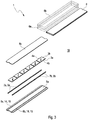
- Fig. 3 shows an exploded view of the PTC heating module 1 in the first embodiment.
- the respective contacting tracks 8a and 8b are fixed in the form of the electroconductive solder layer 14 or the electroconductive adhesive layer 15 and the C-shaped metal elements 9a and 9b are soldered or glued to the respective contacting track 8a and 8b.
- the respective contacting track 8a and 8b is arranged on the insulating board 5a so that an installation space that is available for the contacting is not limited by the thickness of the PTC thermistor elements 2 in the PTC heating module 1. In this advantageous manner, the expenditure for the usually technically elaborate contacting of the PTC thermistor elements 2 can be significantly reduced.
- the PTC thermistor elements 2 are fixed with the main side 3a on the insulating board 5a between the respective metal elements 9a and 9b.
- the metal elements 9a and 9b are electrically contacted with the PTC thermistor elements 2 on the respective lateral surfaces 4a and 4b.
- the other insulating board 5b can be fixed to the main surface 3b of the PTC thermistor elements 2 and the PTC thermistor elements 2 and the adjacent insulating boards 5a and 5b can be arranged in the housing 6 of the PTC heating module 1.
- the respective rib structure 6a and 6b can be fixed to the housing 6 before or after the arranging of the PTC thermistor elements 2 and the adjacent insulating boards 5a and 5b in the housing 6.
- Fig. 4 shows a sectional view of the PTC heating module 1 according to the invention in a second embodiment.
- the respective contacting track 8a and 8b is formed in each case by an elongated circuit board 11 a and 11b each with a conductor 12a and 12b.
- the respective circuit board 11a and 11b is fixed on the insulating board 5a in a firmly bonded manner, preferably by soldering or gluing.
- the respective contact element 7a and 7b in this second embodiment of the PTC heating module 1 is an L-shaped metal element 13a and 13b which is fixed to the conductor 12a and 12b of the respective circuit board 11a and 11b in a firmly bonded manner preferably by soldering or gluing.
- Fig. 5 shows a top view of the individual PTC thermistor elements 2 of the PTC heating module 1 in the second embodiment.
- a total of six PTC thermistor elements 2 are arranged on the insulating board 5a next to one another and electrically contacted with one another and to the outside via the respective joint contacting track 8a and b.
- the respective contact elements 7a and 7b are fixed in a firmly bonded manner.
- the contact elements 7a and 7b are the L-shaped metal elements 13a and 13b, which are soldered or glued to the respective contacting track 8a and 8b in the form of the circuit board 11a and 11b with the conductor 12a and 12b.
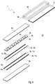
- Fig. 6 shows an exploded view of the PTC heating module 1 in the second embodiment.
- the circuit boards 11a and 11b are fixed on the insulating board 5a in a firmly bonded manner, preferably by soldering or gluing and the L-shaped metal elements 13a and 13b are soldered or glued to the respective conductor 12a and 12b of the respective circuit board 11a and 11b.
- the respective circuit board 11a and 11b in this case is arranged on the insulating board 5a and an installation space that is available for the contacting is not limited by the thickness of the PTC thermistor elements 2 in the PTC heating module 1. Because of this, the effort for the usually technically elaborate contacting of the PTC thermistor elements 2 can be significantly reduced.
- the PTC thermistor elements 2 are fixed with the main side 3a to the insulating board 5a between the respective metal elements 13a and 13b and electrically contacted with these on the respective lateral surfaces 4a and 4b.
- the other insulating board 5b is fixed to the main surface 3b of the PTC thermistor elements 2 and the PTC thermistor elements 2 and the adjacent insulating boards 5a and 5b are arranged in the housing 6 of the PTC heating module 1.
- the respective rib structure 6a and 6b in this case can be fixed to the housing 6 before or after the arranging of the PTC thermistor elements 2 and the adjacent insulating boards 5a and 5b in the housing 6.
- the contacting of the respective PTC thermistor element 2 in the PTC heating module 1 according to the invention and the overall construction of the PTC heating module 1 according to the invention is significantly simplified.
- the contacting of the at least one PTC thermistor element 2 usually involving major technical expenditure is limited by the method 10 according to the invention to a fixing of the respective contact element 7a and 7b on the contacting track 8a and 8b on the respective insulating board 5a.
- an installation space that is available for the contacting is not limited by the thickness of the PTC thermistor elements 2 in the PTC heating module 1. Because of this, the production effort and also the production costs can be reduced.
Landscapes
- Engineering & Computer Science (AREA)
- Chemical & Material Sciences (AREA)
- Ceramic Engineering (AREA)
- Physics & Mathematics (AREA)
- Thermal Sciences (AREA)
- Combustion & Propulsion (AREA)
- Mechanical Engineering (AREA)
- General Engineering & Computer Science (AREA)
- Thermistors And Varistors (AREA)
- Resistance Heating (AREA)
- Air-Conditioning For Vehicles (AREA)
Priority Applications (3)
| Application Number | Priority Date | Filing Date | Title |
|---|---|---|---|
| EP18169850.7A EP3562264A1 (de) | 2018-04-27 | 2018-04-27 | Ptc-heizmodul |
| CN201910302509.4A CN110418441A (zh) | 2018-04-27 | 2019-04-16 | Ptc加热模块 |
| US16/396,250 US20190335543A1 (en) | 2018-04-27 | 2019-04-26 | Ptc heating module |
Applications Claiming Priority (1)
| Application Number | Priority Date | Filing Date | Title |
|---|---|---|---|
| EP18169850.7A EP3562264A1 (de) | 2018-04-27 | 2018-04-27 | Ptc-heizmodul |
Publications (1)
| Publication Number | Publication Date |
|---|---|
| EP3562264A1 true EP3562264A1 (de) | 2019-10-30 |
Family
ID=62196308
Family Applications (1)
| Application Number | Title | Priority Date | Filing Date |
|---|---|---|---|
| EP18169850.7A Pending EP3562264A1 (de) | 2018-04-27 | 2018-04-27 | Ptc-heizmodul |
Country Status (3)
| Country | Link |
|---|---|
| US (1) | US20190335543A1 (de) |
| EP (1) | EP3562264A1 (de) |
| CN (1) | CN110418441A (de) |
Families Citing this family (6)
| Publication number | Priority date | Publication date | Assignee | Title |
|---|---|---|---|---|
| DE102019217693A1 (de) * | 2019-11-18 | 2021-05-20 | Mahle International Gmbh | Heizmodul |
| DE102019220589A1 (de) * | 2019-12-27 | 2021-07-01 | Eberspächer Catem Gmbh & Co. Kg | Wärmeerzeugendes Element und Verfahren zu dessen Herstellung |
| EP3863029A1 (de) * | 2020-02-05 | 2021-08-11 | MAHLE International GmbH | Ptc-thermistor-modul für eine temperatursteuerungsvorrichtung |
| DE102020205305B4 (de) * | 2020-04-27 | 2022-06-30 | Eberspächer Catem Gmbh & Co. Kg | PTC-Heizeinrichtung und Verfahren zu deren Herstellung |
| DE102020113124A1 (de) * | 2020-05-14 | 2021-11-18 | Eberspächer catem Hermsdorf GmbH & Co. KG | PTC-Heizzelle und Verfahren zu deren Herstellung |
| DE102020206546A1 (de) * | 2020-05-26 | 2021-12-02 | Mahle International Gmbh | PTC-Heizmodul und ein Verfahren zur Steuerung des PTC-Heizmoduls |
Citations (5)
| Publication number | Priority date | Publication date | Assignee | Title |
|---|---|---|---|---|
| US4072848A (en) * | 1976-07-22 | 1978-02-07 | Thermon Manufacturing Company | Electrical heating cable with temperature self-limiting heating elements |
| EP0781889A1 (de) * | 1994-09-14 | 1997-07-02 | Sekisui Kaseihin Kogyo Kabushiki Kaisha | Heizvorrichtung und ihre herstellung |
| DE10143852A1 (de) * | 2001-09-06 | 2003-04-03 | Webasto Thermosysteme Gmbh | Heizkörper |
| DE102011081833A1 (de) * | 2011-08-30 | 2013-02-28 | Webasto Ag | Heizvorrichtung mit einem PTC-Heizelement |
| WO2014129287A1 (ja) * | 2013-02-22 | 2014-08-28 | 積水化成品工業株式会社 | 長尺ptcヒーターおよびその使用方法 |
-
2018
- 2018-04-27 EP EP18169850.7A patent/EP3562264A1/de active Pending
-
2019
- 2019-04-16 CN CN201910302509.4A patent/CN110418441A/zh active Pending
- 2019-04-26 US US16/396,250 patent/US20190335543A1/en not_active Abandoned
Patent Citations (5)
| Publication number | Priority date | Publication date | Assignee | Title |
|---|---|---|---|---|
| US4072848A (en) * | 1976-07-22 | 1978-02-07 | Thermon Manufacturing Company | Electrical heating cable with temperature self-limiting heating elements |
| EP0781889A1 (de) * | 1994-09-14 | 1997-07-02 | Sekisui Kaseihin Kogyo Kabushiki Kaisha | Heizvorrichtung und ihre herstellung |
| DE10143852A1 (de) * | 2001-09-06 | 2003-04-03 | Webasto Thermosysteme Gmbh | Heizkörper |
| DE102011081833A1 (de) * | 2011-08-30 | 2013-02-28 | Webasto Ag | Heizvorrichtung mit einem PTC-Heizelement |
| WO2014129287A1 (ja) * | 2013-02-22 | 2014-08-28 | 積水化成品工業株式会社 | 長尺ptcヒーターおよびその使用方法 |
Also Published As
| Publication number | Publication date |
|---|---|
| CN110418441A (zh) | 2019-11-05 |
| US20190335543A1 (en) | 2019-10-31 |
Similar Documents
| Publication | Publication Date | Title |
|---|---|---|
| EP3562264A1 (de) | Ptc-heizmodul | |
| US8592231B2 (en) | LED package structure and manufacturing method, and LED array module | |
| CN100565871C (zh) | 具有材料结合设置的接线元件的功率半导体模块 | |
| US20020173192A1 (en) | Power semiconductor module with pressure contact means | |
| CN1700453B (zh) | 与功率半导体模块形成压力接触的结构 | |
| US20110220638A1 (en) | Finned ceramic heater | |
| US20100066482A1 (en) | Electronic component with lead wire | |
| US6807041B2 (en) | Electronic triggering for heating elements | |
| CN101261987B (zh) | 电子部件安装板 | |
| CN106796843A (zh) | 具有能够导热的连接元件的电容的器件 | |
| JP2016503237A (ja) | 一体型ヒートスプレッダを備えたパワー抵抗器 | |
| JP2000164780A (ja) | パワ―電子部品 | |
| KR100990527B1 (ko) | 휨저항성 기부판을 갖는 전력 반도체 모듈 | |
| CN112005326B (zh) | 具有外部接触的多层结构元件 | |
| JP2002289630A (ja) | パワー半導体モジュール | |
| KR100840796B1 (ko) | 세라믹 발열체용 단자 | |
| US20240133587A1 (en) | PTC Heating Element, Electric Heating Device and Use of a PTC Heating Element | |
| JP2000068102A (ja) | 抵抗器 | |
| JPH11251186A (ja) | スタック型セラミックコンデンサ | |
| US20050167414A1 (en) | Cooking device with a thick film resistive element heater | |
| JP2017054961A (ja) | 抵抗器 | |
| CN104867903A (zh) | 电子模块 | |
| KR101079325B1 (ko) | 금속박판을 사용하는 열전소자 | |
| CN112635429A (zh) | 一种功率器件及其基板 | |
| JP4855585B2 (ja) | 圧電トランス |
Legal Events
| Date | Code | Title | Description |
|---|---|---|---|
| PUAI | Public reference made under article 153(3) epc to a published international application that has entered the european phase |
Free format text: ORIGINAL CODE: 0009012 |
|
| STAA | Information on the status of an ep patent application or granted ep patent |
Free format text: STATUS: THE APPLICATION HAS BEEN PUBLISHED |
|
| AK | Designated contracting states |
Kind code of ref document: A1 Designated state(s): AL AT BE BG CH CY CZ DE DK EE ES FI FR GB GR HR HU IE IS IT LI LT LU LV MC MK MT NL NO PL PT RO RS SE SI SK SM TR |
|
| AX | Request for extension of the european patent |
Extension state: BA ME |
|
| STAA | Information on the status of an ep patent application or granted ep patent |
Free format text: STATUS: REQUEST FOR EXAMINATION WAS MADE |
|
| 17P | Request for examination filed |
Effective date: 20200210 |
|
| RBV | Designated contracting states (corrected) |
Designated state(s): AL AT BE BG CH CY CZ DE DK EE ES FI FR GB GR HR HU IE IS IT LI LT LU LV MC MK MT NL NO PL PT RO RS SE SI SK SM TR |
|
| STAA | Information on the status of an ep patent application or granted ep patent |
Free format text: STATUS: EXAMINATION IS IN PROGRESS |
|
| 17Q | First examination report despatched |
Effective date: 20210202 |
|
| GRAP | Despatch of communication of intention to grant a patent |
Free format text: ORIGINAL CODE: EPIDOSNIGR1 |
|
| STAA | Information on the status of an ep patent application or granted ep patent |
Free format text: STATUS: GRANT OF PATENT IS INTENDED |
|
| INTG | Intention to grant announced |
Effective date: 20250826 |
|
| STAA | Information on the status of an ep patent application or granted ep patent |
Free format text: STATUS: THE APPLICATION IS DEEMED TO BE WITHDRAWN |