EP3562384B1 - Tragbares system zur überwachung von hirntrauma - Google Patents
Tragbares system zur überwachung von hirntrauma Download PDFInfo
- Publication number
- EP3562384B1 EP3562384B1 EP17885519.3A EP17885519A EP3562384B1 EP 3562384 B1 EP3562384 B1 EP 3562384B1 EP 17885519 A EP17885519 A EP 17885519A EP 3562384 B1 EP3562384 B1 EP 3562384B1
- Authority
- EP
- European Patent Office
- Prior art keywords
- head
- sensors
- brainwave
- user
- readings
- Prior art date
- Legal status (The legal status is an assumption and is not a legal conclusion. Google has not performed a legal analysis and makes no representation as to the accuracy of the status listed.)
- Active
Links
Images

Classifications
-
- A—HUMAN NECESSITIES
- A61—MEDICAL OR VETERINARY SCIENCE; HYGIENE
- A61B—DIAGNOSIS; SURGERY; IDENTIFICATION
- A61B5/00—Measuring for diagnostic purposes; Identification of persons
- A61B5/40—Detecting, measuring or recording for evaluating the nervous system
- A61B5/4058—Detecting, measuring or recording for evaluating the nervous system for evaluating the central nervous system
- A61B5/4064—Evaluating the brain
-
- A—HUMAN NECESSITIES
- A42—HEADWEAR
- A42B—HATS; HEAD COVERINGS
- A42B3/00—Helmets; Helmet covers ; Other protective head coverings
- A42B3/04—Parts, details or accessories of helmets
- A42B3/0406—Accessories for helmets
- A42B3/0433—Detecting, signalling or lighting devices
- A42B3/046—Means for detecting hazards or accidents
-
- A—HUMAN NECESSITIES
- A42—HEADWEAR
- A42B—HATS; HEAD COVERINGS
- A42B3/00—Helmets; Helmet covers ; Other protective head coverings
- A42B3/04—Parts, details or accessories of helmets
- A42B3/30—Mounting radio sets or communication systems
-
- A—HUMAN NECESSITIES
- A61—MEDICAL OR VETERINARY SCIENCE; HYGIENE
- A61B—DIAGNOSIS; SURGERY; IDENTIFICATION
- A61B5/00—Measuring for diagnostic purposes; Identification of persons
- A61B5/02—Detecting, measuring or recording for evaluating the cardiovascular system, e.g. pulse, heart rate, blood pressure or blood flow
- A61B5/0205—Simultaneously evaluating both cardiovascular conditions and different types of body conditions, e.g. heart and respiratory condition
-
- A—HUMAN NECESSITIES
- A61—MEDICAL OR VETERINARY SCIENCE; HYGIENE
- A61B—DIAGNOSIS; SURGERY; IDENTIFICATION
- A61B5/00—Measuring for diagnostic purposes; Identification of persons
- A61B5/24—Detecting, measuring or recording bioelectric or biomagnetic signals of the body or parts thereof
- A61B5/316—Modalities, i.e. specific diagnostic methods
- A61B5/369—Electroencephalography [EEG]
- A61B5/386—Accessories or supplementary instruments therefor
-
- A—HUMAN NECESSITIES
- A61—MEDICAL OR VETERINARY SCIENCE; HYGIENE
- A61B—DIAGNOSIS; SURGERY; IDENTIFICATION
- A61B5/00—Measuring for diagnostic purposes; Identification of persons
- A61B5/68—Arrangements of detecting, measuring or recording means, e.g. sensors, in relation to patient
- A61B5/6801—Arrangements of detecting, measuring or recording means, e.g. sensors, in relation to patient specially adapted to be attached to or worn on the body surface
- A61B5/6802—Sensor mounted on worn items
- A61B5/6803—Head-worn items, e.g. helmets, masks, headphones or goggles
-
- A—HUMAN NECESSITIES
- A61—MEDICAL OR VETERINARY SCIENCE; HYGIENE
- A61B—DIAGNOSIS; SURGERY; IDENTIFICATION
- A61B5/00—Measuring for diagnostic purposes; Identification of persons
- A61B5/74—Details of notification to user or communication with user or patient; User input means
- A61B5/746—Alarms related to a physiological condition, e.g. details of setting alarm thresholds or avoiding false alarms
-
- G—PHYSICS
- G01—MEASURING; TESTING
- G01L—MEASURING FORCE, STRESS, TORQUE, WORK, MECHANICAL POWER, MECHANICAL EFFICIENCY, OR FLUID PRESSURE
- G01L5/00—Apparatus for, or methods of, measuring force, work, mechanical power, or torque, specially adapted for specific purposes
- G01L5/0052—Apparatus for, or methods of, measuring force, work, mechanical power, or torque, specially adapted for specific purposes measuring forces due to impact
-
- A—HUMAN NECESSITIES
- A61—MEDICAL OR VETERINARY SCIENCE; HYGIENE
- A61B—DIAGNOSIS; SURGERY; IDENTIFICATION
- A61B2503/00—Evaluating a particular growth phase or type of persons or animals
- A61B2503/10—Athletes
-
- A—HUMAN NECESSITIES
- A61—MEDICAL OR VETERINARY SCIENCE; HYGIENE
- A61B—DIAGNOSIS; SURGERY; IDENTIFICATION
- A61B5/00—Measuring for diagnostic purposes; Identification of persons
- A61B5/02—Detecting, measuring or recording for evaluating the cardiovascular system, e.g. pulse, heart rate, blood pressure or blood flow
- A61B5/024—Measuring pulse rate or heart rate
-
- A—HUMAN NECESSITIES
- A61—MEDICAL OR VETERINARY SCIENCE; HYGIENE
- A61B—DIAGNOSIS; SURGERY; IDENTIFICATION
- A61B5/00—Measuring for diagnostic purposes; Identification of persons
- A61B5/68—Arrangements of detecting, measuring or recording means, e.g. sensors, in relation to patient
- A61B5/6801—Arrangements of detecting, measuring or recording means, e.g. sensors, in relation to patient specially adapted to be attached to or worn on the body surface
- A61B5/6813—Specially adapted to be attached to a specific body part
- A61B5/6814—Head
- A61B5/6815—Ear
-
- A—HUMAN NECESSITIES
- A61—MEDICAL OR VETERINARY SCIENCE; HYGIENE
- A61B—DIAGNOSIS; SURGERY; IDENTIFICATION
- A61B5/00—Measuring for diagnostic purposes; Identification of persons
- A61B5/68—Arrangements of detecting, measuring or recording means, e.g. sensors, in relation to patient
- A61B5/6887—Arrangements of detecting, measuring or recording means, e.g. sensors, in relation to patient mounted on external non-worn devices, e.g. non-medical devices
- A61B5/6895—Sport equipment
Definitions
- the invention relates to a portable system for monitoring brain trauma.
- Mild Traumatic Brain Injury (also referred to as concussions, Mild Head Injury (MHI), minor head trauma, mild brain injury, etc.), are common and dangerous occurrences.
- TBI traumatic brain injury
- Subconcussive impacts can also be a cause for concern. These blows show no concussion symptoms, yet damage the brain. Changes to the brain caused by subconcussive forces are associated with the number of impacts. The brain damage caused by subconcussive forces was originally suspected to result in mild cognitive impairment. However, chronic depression and chronic traumatic encephalopathy (CTE) are also possible outcomes/conditions. The subconcussive impacts can cause significant changes in the white matter nerves. The limbic lobe and subcortical region of the brain are also changed.
- US Patent No. 7,904,144 (Causevic et al.), published on March 8, 2011 , discloses a method and apparatus for performing rapid brain assessment may provide emergency triage to head trauma patients by analyzing a combination of spontaneous and evoked brain potentials. The spontaneous and evoked potentials are analyzed, and the results classified, to present a real-time assessment of a patient's brain, diagnosing any potential abnormalities therein.
- US 2012/223833 A1 published on September 6, 2012 , discloses a portable wireless personal head impact reporting system. Properties of angular velocities, such as jerk and jolt are calculated based on sensed velocities; and by comparing these to threshold values the severity of injury may be predicted.
- US 2016/021330 published on July 28, 2016 , discloses aspects related to traumatic brain injuries, specifically in the field of sports. Player acceleration data and game time player status data are used to determine brain injury status data.
- US 2016/100794 A1 published on April 14, 2016 , relates to a wearable platform for implementing real time brain trauma treatment, wherein a wearable map of EEG points is used to provide real-time information on a wearer's brain condition. If stress forces are detected, a cooling agent is ejected to reduce brain temperature.
- a non-invasive system for monitoring brain trauma comprising: a plurality of spaced apart brainwave sensors configured to monitor brainwaves of a user of the system; one or more force determination sensors, configured to determine an amount of force exerted on the user's head; and a processing resource, comprised within a head-worn device, configured to: obtain a plurality of brainwave readings from the brainwave sensors and a plurality of force readings from the force determination sensors; upon (a) the force readings indicating that the amount of force exerted on the user's head at a given time exceeds a threshold, and (b) the brainwave readings indicating abnormal brain activity resulting from the force exerted on the user's head at the given time: estimate an affected brain area utilizing the time difference between the given time and the times at which each of the brainwave readings indicating abnormal brain activity resulting from the force exerted on the user's head at the given time was obtained by the respective brain
- the brainwave sensors and the force determination sensors are comprised within a head-worn device.
- the head-worn device is a helmet, having padding for attaching the brainwave sensors to corresponding locations on the user's head.
- the head-worn device is a headband attaching the brainwave sensors to corresponding locations on the user's head.
- the head-worn device includes at least one ear-worn device attachable to the user's ear.
- system further comprises a heartbeat sensor configured to monitor heartbeats of the user and the processing resource is further configured to obtain a plurality of heartbeat readings from the heartbeat sensor and to provide the notification upon the heartbeat readings indicating a missing heartbeat.
- the estimation is performed utilizing a magnitude and a time difference of a detected electrical echo in at least two of the brainwave readings obtained by at least two corresponding distinct brainwave sensors of the brainwave sensors.
- the notification includes an indication of the affected brain area.
- the brainwave sensors are passive sensors.
- the notification is provided to a second user, other than the user.
- a method of monitoring brain trauma using a non-invasive system comprising: a plurality of spaced apart brainwave sensors configured to monitor brainwaves of a user of the system; one or more force determination sensors, configured to determine an amount of force exerted on the user's head; and a processing resource comprised within a head-worn device; the method comprising: obtaining, by the processing resource, a plurality of brainwave readings from the brainwave sensors and a plurality of force readings from the force determination sensors; upon (a) the force readings indicating that the amount of force exerted on the user's head at a given time exceeds a threshold, and (b) the brainwave readings indicating abnormal brain activity resulting from the force exerted on the user's head at the given time: estimating an affected brain area utilizing the time difference between the given time and the times at which each of the brainwave readings indicating abnormal brain activity resulting from the force exerted
- the brainwave sensors and the force determination sensors are comprised within a head-worn device.
- the head-worn device is a helmet, having padding for attaching the brainwave sensors to corresponding locations on the user's head.
- the head-worn device is a headband attaching the brainwave sensors to corresponding locations on the user's head.
- the head-worn device includes at least one ear-worn device attachable to the user's ear.
- the non-invasive system further comprises a heartbeat sensor configured to monitor heartbeats of the user and wherein the method further comprises obtaining a plurality of heartbeat readings from the heartbeat sensor and providing the notification upon the heartbeat readings indicating a missing heartbeat.
- the estimation is performed utilizing a magnitude and a time difference of a detected electrical echo in at least two of the brainwave readings obtained by at least two corresponding distinct brainwave sensors of the brainwave sensors.
- the brainwave sensors are passive sensors.
- the notification is provided to a second user, other than the user.
- a non-transitory computer readable storage medium having computer readable program code embodied therewith, the computer readable program code executable by at least one processor of a non-invasive system to perform a method, the non-invasive system comprising a plurality of spaced-apart brainwave sensors configured to monitor brainwaves of a user of the system, and one or more force determination sensors, configured to determine an amount of force exerted on the user's head; the method comprising: obtaining, by a processing resource comprised within a head-worn device, a plurality of brainwave readings from the brainwave sensors and a plurality of force readings from the force determination sensors; upon (a) the force readings indicating that the amount of force exerted on the user's head at a given time exceeds a threshold, and (b) the brainwave readings indicating abnormal brain activity resulting from the force exerted on the user's head at the given time: estimating an affected brain area utilizing
- DSP digital signal processor
- FPGA field programmable gate array
- ASIC application specific integrated circuit
- non-transitory is used herein to exclude transitory, propagating signals, but to otherwise include any volatile or non-volatile computer memory technology suitable to the application.
- the phrase “for example,” “such as”, “for instance” and variants thereof describe non-limiting embodiments of the presently disclosed subject matter.
- Reference in the specification to “one case”, “some cases”, “other cases” or variants thereof means that a particular feature, structure or characteristic described in connection with the embodiment(s) is included in at least one embodiment of the presently disclosed subject matter.
- the appearance of the phrase “one case”, “some cases”, “other cases” or variants thereof does not necessarily refer to the same embodiment(s).
- Figs. 1-4 illustrate a general schematic of the system architecture in accordance with an embodiment of the presently disclosed subject matter.
- Each module in Figs. 1-4 can be made up of any combination of software, hardware and/or firmware that performs the functions as defined and explained herein.
- the modules in Figs. 1-4 may be centralized in one location or dispersed over more than one location.
- the system may comprise fewer, more, and/or different modules than those shown in Figs. 1-4 .
- FIG. 1 showing a schematic illustration of a head-worn device, in accordance with the presently disclosed subject matter.
- a head-worn device 110 such as the helmet shown in the illustration, or a headband, or any other head-worn device, including devices worn on and/or inside the ears of the person wearing the device (for the sake of clarity - the term "head-worn device" according to the presently disclosed subject matter is to be construed as including also ear-worn device/s attachable to an earls), is provided.
- the head-worn device 110 comprises a plurality of spaced apart brainwave sensors 112 configured to monitor brainwaves of a person wearing the head-worn device 110.
- the brainwave sensors 112 can be, for example, passive sensors, such as Electroencephalography (EEG) electrodes, or other types of sensors.
- EEG Electroencephalography
- the brainwave sensors 112 can be active sensors such as ones used in Near Infrared Spectroscopy (NIRS).
- NIRS Near Infrared Spectroscopy
- the brainwave sensors 112 can be positioned so that in the contact points thereof with the head of the person wearing the head-worn device 110 there is no hair, or the hair is low-cut, as in some cases the less hair there is the better the reading quality is expected to be.
- Such points can be, for example, the forehead, the neck, near the ears, on the temples (located on the side of the head, behind the eyes).
- a first brainwave sensor 112 and a second brainwave sensor 112 are positioned so that one contacts the top of the forehead of the person wearing the head-worn device 110 above the left eye and the other contacts the top of the forehead of the person wearing the head-worn device 110 above the right eye; a third brainwave sensor 112 is positioned so that it contacts a spot between the left ear and the left sideburn of the person wearing the head-worn device 110; a fourth brainwave sensor 112 is positioned so that it contacts a spot between the right ear and the right sideburn of the person wearing the head-worn device 110; a fifth brainwave sensor 112 and a sixth brainwave sensor 112 are positioned so that they contact the left and right sides of the back of the neck of the person wearing the head-worn device 110 respectively, and a seventh brainwave sensor 112 and eighth brainwave sensor 112 are positioned so that they contact the left and right temples of the person wearing the head-worn device 110 respectively.
- the brainwave sensors 112 can be positioned in other manners, mutatis mutandis. It is to be further noted that in order for the brainwave sensors 112 to be pressed against the contact points on the head of the person wearing the head-worn device 110, padding can be placed in an appropriate manner inside the head-worn device 110, while making sure that it does not interfere with the operation of the various sensors. In some cases, the padding can also be used to cushion various impacts.
- the head-worn device 110 further comprises one or more force determination sensors 114, configured to determine an amount of force exerted on the head of the person wearing the head-worn device 110.
- the force determination sensors 114 can be Force Sensing Resistors (FSRs), Piezoelectric sensors, accelerometer, any other sensor capable of obtaining information that enables determining a force exerted on the head of the person wearing the head-worn device 110, or any combination of two or more of those sensor types.
- FSRs Force Sensing Resistors
- Piezoelectric sensors Piezoelectric sensors
- accelerometer any other sensor capable of obtaining information that enables determining a force exerted on the head of the person wearing the head-worn device 110, or any combination of two or more of those sensor types.
- a first and a second force determination sensors 114 are positioned so that they contact substantially the center of the left and right hemispheres on the top of the head of the person wearing the head-worn device 110, a third force determination sensor 114 is positioned so that it contacts substantially the middle of the forehead of the person wearing the head-worn device 110, a fourth force determination sensor 114 is positioned so that it contacts substantially the middle of the back of the head of the person wearing the head-worn device 110, a fifth and sixth force determination sensors 114 are positioned so that they contact substantially the middle of the left and right sides of the head of the person wearing the head-worn device 110 respectively, and four additional force determination sensors 114 are positioned so that they contact the front-right, front-left back-right and back-left corners of the head of the person wearing the head-worn device 110 respectively. It is to be noted that this is merely one example and the force determination sensors 114 can be positioned in other manners, mutatis mutandis.
- the head-worn device 110 further comprises one or more heartbeat sensors 116 configured to monitor heartbeats of the person wearing the head-worn device 110.
- the heartbeat sensors 116 can be located on areas where the blood vessels are close to the surface, such as the ears.
- a heartbeat sensor 116 can be attached to, or tightly pressed against, an ear of the person wearing the head-worn device 110, and optionally a second heartbeat sensor 116 can be attached to, or tightly pressed against, the other ear of the person wearing the head-worn device 110.
- this is merely one example and the heartbeat sensors 116 can be positioned in other manners, mutatis mutandis.
- the heartbeat sensors 116 can use out of skin technology such as flow monitoring using light or the change in pressure/signals due to the flow of blood in a place like the ears, etc.
- the head-worn device 110 can optionally also comprise one or more notification elements 120, that can enable providing notifications to the person wearing the head-worn device 110, as further detailed herein, inter alia with reference to Fig. 5 .
- the notification elements 120 can be vibrating elements and/or speakers and/or lights and/or any other device that can generate a notification that can be sensed by the person wearing the head-worn device 110.
- the head-worn device 110 can optionally be a standalone unit, having data storage and processing capabilities.
- the head-worn device 110 can further comprise a data repository 124 and a processing resource 122.
- the processing resource 122 can be one or more processing units (e.g. central processing units), microprocessors, microcontrollers (e.g. microcontroller units (MCUs)) or any other computing devices or modules, including multiple and/or parallel and/or distributed processing units, which are adapted to independently or cooperatively process data for controlling relevant head-worn device 110 resources and for enabling operations related to head-worn device 110 resources, as further detailed with respect to Fig. 4 .
- processing units e.g. central processing units
- microprocessors e.g. microcontroller units (MCUs)
- MCUs microcontroller units
- the data repository 124 (e.g. a database, a storage system, a memory including Read Only Memory - ROM, Random Access Memory - RAM, or any other type of memory, etc.) can be configured to store data, including, inter alia, information of readings obtained by the sensors and/or pre-determined or dynamically calculated thresholds to be compared with such readings, etc.
- data repository 124 can be further configured to enable retrieval and/or update and/or deletion of the stored data. It is to be noted that in some cases, data repository 124 can be distributed (for example, part of the data repository can be local (i.e. inside the head worn device), and another part can thereof be external (e.g. within the external processing system 140)).
- the head-worn device 110 can further include a network interface 118.
- Network interface 118 can enable wirelessly connecting the head-worn device 110 to the communication network 130 and can enable it to send and receive data sent thereto through the communication network 130, including sending readings from the various sensors (the brainwave sensors 112, the force determination sensors 114, the heartbeat sensors 116) to an external processing system 140, sending commands for operating external output means to provide various notifications, etc., as further detailed herein, inter alia with reference to Fig. 5 .
- head-worn devices such as a headband, or other types of head worn devices, can be used, mutatis mutandis.
- FIG. 2 there is shown a schematic illustration of a system including a plurality of head-worn devices, in accordance with the presently disclosed subject matter.
- a system 10 comprising a plurality of head-worn devices (shown in the illustration as 110-a, 110-b, ..., 110-n).
- Each of the head-worn devices (110-a, ..., 110-n) is a head-worn device in accordance with the teachings of the above description of Fig. 1 .
- Such system 10, comprising a plurality of head-worn devices (110-a, ..., 110-n) can be used for example by sports teams, such as Football (also known as American Football or gridiron) teams, where each player wears a head-worn device 110.
- sports teams such as Football (also known as American Football or gridiron) teams, where each player wears a head-worn device 110.
- the plurality of head-worn devices 110-a, ..., 110-n can be connected to a communication network 130, through which the data collected by the plurality of sensors (including the brainwave sensors 112 and/or the force determination sensors 114 and/or the heartbeat sensors 116) can be sent to an external processing system 140, for data storage and processing as further detailed herein, inter alia with reference to Fig. 5 .
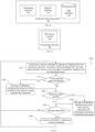
- FIG. 3 showing a block diagram schematically illustrating an external processing system, in accordance with the presently disclosed subject matter.
- the external processing system 140 can comprise a network interface 210.
- Network interface 210 can enable wirelessly connecting the external processing system 140 to communication network 130 and can enable it to send and receive data sent thereto through the communication network 130, including receiving readings from the various sensors (the brainwave sensors 112, the force determination sensors 114, the heartbeat sensors 116) of the head-worn devices (110-a, ..., 110-n), etc., as further detailed herein, inter alia with reference to Fig. 5 .
- the external processing system 140 can further comprise a processing resource 122 and/or a data repository 124.
- the processing resource 122 can be one or more processing units (e.g. central processing units), microprocessors, microcontrollers (e.g. microcontroller units (MCUs)) or any other computing devices or modules, including multiple and/or parallel and/or distributed processing units, which are adapted to independently or cooperatively process data for controlling relevant external processing system 140 resources and for enabling operations related to external processing system 140 resources, as further detailed with respect to Fig. 4 .
- processing units e.g. central processing units
- microprocessors e.g. microcontroller units (MCUs)
- MCUs microcontroller units
- the data repository 124 (e.g. a database, a storage system, a memory including Read Only Memory - ROM, Random Access Memory - RAM, or any other type of memory, etc.) can be configured to store data, including, inter alia, information of readings obtained by the sensors and/or pre-determined or dynamically calculated thresholds to be compared with such readings, etc.
- data repository 124 can be further configured to enable retrieval and/or update and/or deletion of the stored data. It is to be noted that in some cases, data repository 124 can be distributed.
- Fig. 4 is a block diagram schematically illustrating a processing resource, in accordance with the presently disclosed subject matter.
- the processing in accordance with the presently disclosed subject matter can be performed by a processing resource 122 comprised within one or more of the head-worn devices (110-a to 110-n), or within an external processing system 140.
- the processing can be performed by a plurality of processing resources 122 that can be optionally distributed between one or more head-worn devices 110 and/or one or more external processing systems 140.
- the processing resource 122 can comprise a monitoring module 240.
- the monitoring module 240 can be configured to monitor brain trauma of one or more persons wearing one or more respective head-worn devices 110.
- attention is drawn to Fig. 5 where a flowchart illustrating one example of a sequence of operations carried out for monitoring brain trauma, in accordance with the presently disclosed subject matter, is shown.
- processing resource 122 (that, as indicated herein, can be comprised within one or more of the head-worn devices (110-a to 110-n), and/or within an external processing system 140) can be configured to perform a monitoring process 500, e.g. utilizing the monitoring module 240.
- processing resource 122 can be configured to continuously obtain, from each of the one or more head-worn devices (e.g. head-worn devices 110-a to 110-n), a plurality of brainwave readings from the corresponding brainwave sensors 112, a plurality of force readings from the force determination sensors 114 and optionally a plurality of heartbeat readings from the heartbeat sensor/s 116 (block 510).
- head-worn devices e.g. head-worn devices 110-a to 110-n
- processing resource 122 can be configured to continuously obtain, from each of the one or more head-worn devices (e.g. head-worn devices 110-a to 110-n), a plurality of brainwave readings from the corresponding brainwave sensors 112, a plurality of force readings from the force determination sensors 114 and optionally a plurality of heartbeat readings from the heartbeat sensor/s 116 (block 510).
- the processing resource 122 can be further configured to check if any of the force readings obtained from each head-worn device 110 exceed a pre-defined threshold (block 515), and if so - provide a notification indicating that the amount of force exerted on the head of the person wearing the corresponding head-worn device 110 exceeded the predetermined threshold (block 520).
- the threshold can be set as 20g/30g/35g or any other pre-determined force.
- a force of 30g is likely to cause a concussion.
- the threshold can be set to be a pre-determined number of blows, during a given time window (e.g. during a single American Football game, during a single quarter of an American Football game, during five minutes, etc.), each exceeding a second threshold that can be set as 5g110g115g.
- a second threshold that can be set as 5g110g115g.
- the notification can be provided to the person wearing the corresponding head-worn device 110, e.g. utilizing the notification elements 120. Additionally, or alternatively, the notification can be provided to another user, such as a coach of the sports team or any other person in charge of monitoring the medical condition of the players wearing the head-worn devices (110-a to 110-n), e.g. via an output mechanism such as a display (including, for example, a display of a smartphone, e.g. by sending a text message to the user), speakers, vibrating elements, or any other output device accessible to such user.
- an output mechanism such as a display (including, for example, a display of a smartphone, e.g. by sending a text message to the user), speakers, vibrating elements, or any other output device accessible to such user.
- the processing resource 122 can check if any of the brainwave readings obtained from each head-worn device 110 indicate an abnormal brain activity (block 525).
- An abnormal brain activity can be indicative of brain trauma.
- the brainwave readings can be compared with information indicative of normal readings.
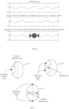
- the information indicative of normal readings can be generic (i.e. not specific to the person wearing the corresponding head-worn device 110), or personalized (i.e. specific to the person wearing the corresponding head-worn device 110). If the brainwave readings are indicative of abnormal brain activity (e.g. deviating from the normal EEG form, for example as shown in Fig.
- the processing resource 122 can be configured to provide a notification indicating that the brain activity of the person wearing the corresponding head-worn device 110 is abnormal (block 530).
- the notification can be provided to the person wearing the corresponding head-worn device 110, e.g. utilizing the notification elements 120. Additionally, or alternatively, the notification can be provided to another user, such as a coach of the sports team or any other person in charge of monitoring the medical condition of the players wearing the head-worn devices (110-a to 110-n), e.g. via an output mechanism such as a display (including, for example, a display of a smartphone, e.g. by sending a text message to the user), speakers, vibrating elements, or any other output device accessible to such user.
- a display including, for example, a display of a smartphone, e.g. by sending a text message to the user
- speakers vibrating elements, or any other output device accessible to such user.
- the processing resource 122 can be further configured to estimate an affected brain area of the person wearing the corresponding head-worn device 110. Such estimation can be performed utilizing a magnitude and a time difference between the force determination sensors 114 detecting a force and the brainwave sensors 112 detecting abnormal brain activity.
- Fig. 7 showing three examples of estimating an affected brain area, in accordance with the presently disclosed subject matter.
- marked "A” a single brainwave sensor 112 picks up an abnormal brain activity. Utilizing the time difference between the time at which the force determination sensors 114 detected a force, and the time at which the brainwave sensor 112 picked up the abnormal brain activity, the distance of the affected brain area can be estimated.
- the estimated affected brain area is shown by the arc marked "possible locations”.
- marked "B” two brainwave sensors 112 pick up abnormal brain activity, each at a certain corresponding point in time.
- the distance of the affected brain area from each sensor can be estimated, and the intersection point of the arcs representing the calculated distance from each brainwave sensor 112 - is the estimated affected brain area.
- both brainwave sensors are placed on the same side of the head of the person wearing the head-worn device.
- the example marked “C” shows a scenario at which the brainwave sensors that pick up the abnormal brain activity are located at opposite sides of the head. In such scenario, there are two intersection points between the arcs representing the calculated distances from the corresponding brainwave sensors 112, both of which are possible affected brain areas. It can be appreciated that having information from more than two brainwave sensors 112 can enable a more accurate estimation of the affected brain area, and having at least three brainwave sensors 112 can enable a three-dimensional estimation.
- the processing resource 122 can obtain heartbeat readings (e.g. in cases where at least one head-worn device 110 comprises one or more heartbeat sensors 116), the processing resource 122 can be further configured to check for missing heartbeats (block 535). In some cases, when a person is hit, it may result in the heart missing a beat. Missing a heartbeat is indicative of brain trauma or another serious condition. If a missing heartbeat is identified, the processing resource 122 can be configured to provide a notification indicating that the heart of the person wearing the corresponding head-worn device 110 missed a beat (block 530). The notification can be provided to the person wearing the corresponding head-worn device 110, e.g. utilizing the notification elements 120.
- the notification can be provided to another user, such as a coach of the sports team or any other person in charge of monitoring the medical condition of the players wearing the head-worn devices (110-a to 110-n), e.g. via an output mechanism such as a display (including, for example, a display of a smartphone, e.g. by sending a text message to the user), speakers, vibrating elements, or any other output device accessible to such user.
- an output mechanism such as a display (including, for example, a display of a smartphone, e.g. by sending a text message to the user), speakers, vibrating elements, or any other output device accessible to such user.
- some of the blocks can be integrated into a consolidated block or can be broken down to a few blocks and/or other blocks may be added. Furthermore, in some cases, the blocks can be performed in a different order than described herein (for example, blocks 525 and 530 can be performed before blocks 515 and 520, blocks 535 and 540 can be performed before blocks 525 and 530, etc.). It is to be further noted that some of the blocks are optional. It should be also noted that whilst the flow diagram is described also with reference to the system elements that realizes them, this is by no means binding, and the blocks can be performed by elements other than those described herein.
- system can be implemented, at least partly, as a suitably programmed computer.
- the presently disclosed subject matter contemplates a computer program being readable by a computer for executing the disclosed method.
- the presently disclosed subject matter further contemplates a machine-readable memory tangibly embodying a program of instructions executable by the machine for executing the disclosed method.
Landscapes
- Health & Medical Sciences (AREA)
- Life Sciences & Earth Sciences (AREA)
- Physics & Mathematics (AREA)
- Medical Informatics (AREA)
- Surgery (AREA)
- Veterinary Medicine (AREA)
- Public Health (AREA)
- Biophysics (AREA)
- Pathology (AREA)
- Engineering & Computer Science (AREA)
- Biomedical Technology (AREA)
- Heart & Thoracic Surgery (AREA)
- General Health & Medical Sciences (AREA)
- Molecular Biology (AREA)
- Animal Behavior & Ethology (AREA)
- Neurology (AREA)
- Physiology (AREA)
- Psychology (AREA)
- Cardiology (AREA)
- Psychiatry (AREA)
- Neurosurgery (AREA)
- General Physics & Mathematics (AREA)
- Pulmonology (AREA)
- Measurement And Recording Of Electrical Phenomena And Electrical Characteristics Of The Living Body (AREA)
Claims (9)
- Nichtinvasives System zur Überwachung von Hirntrauma, wobei das System Folgendes umfasst:- eine Vielzahl zueinander beabstandeter Gehirnwellensensoren (112), die dazu konfiguriert sind, Gehirnwellen eines Benutzers des Systems zu überwachen;- einen oder mehrere Kraftbestimmungssensoren (114), die dazu konfiguriert sind, eine Kraftmenge, die auf den Kopf des Benutzers ausgeübt wird, zu bestimmen; und- eine Verarbeitungsressource (122), die innerhalb einer an dem Kopf getragenen Vorrichtung (110) umfasst ist, wobei die Verarbeitungsressource zu Folgendem konfiguriert ist:Erlangen einer Vielzahl von Gehirnwellenmesswerten von den Gehirnwellensensoren (112) und einer Vielzahl von Kraftmesswerten von den Kraftbestimmungssensoren (114);wenn (a) die Kraftmesswerte anzeigen, dass die Kraftmenge, die zu einem gegebenen Zeitpunkt auf den Kopf des Benutzers ausgeübt wird, einen Schwellenwert überschreitet, und (b) die Gehirnwellenmesswerte abnormale Gehirnaktivität infolge der Kraft, die zu dem gegebenen Zeitpunkt auf den Kopf des Benutzers ausgeübt wird, anzeigen: Schätzen eines betroffenen Gehirnbereichs unter Verwendung der Zeitdifferenz zwischen dem gegebenen Zeitpunkt und den Zeitpunkten, zu denen jeder der Gehirnwellenmesswerte, die abnormale Gehirnaktivität infolge der Kraft, die zu dem gegebenen Zeitpunkt auf den Kopf des Benutzers ausgeübt wurde, anzeigen, durch die jeweiligen Gehirnwellensensoren (112) erlangt wurde; und Bereitstellen einer Benachrichtigung, die eine Anzeige des betroffenen Gehirnbereichs beinhaltet,wobei die Gehirnwellensensoren (112) und die Kraftbestimmungssensoren (114) innerhalb der an dem Kopf getragenen Vorrichtung (110) umfasst sind.
- Nichtinvasives System nach Anspruch 1, wobei die an dem Kopf getragene Vorrichtung (110) ein Helm ist, der ein Futter zum Befestigen der Gehirnwellensensoren (112) an entsprechenden Stellen an dem Kopf des Benutzers aufweist.
- Nichtinvasives System nach Anspruch 1, wobei die an dem Kopf getragene Vorrichtung (110) ein Kopfband ist, das die Gehirnwellensensoren (112) an entsprechenden Stellen an dem Kopf des Benutzers befestigt.
- Nichtinvasives System nach Anspruch 1, wobei die an dem Kopf getragene Vorrichtung (110) mindestens eine an dem Ohr getragene Vorrichtung beinhaltet, die an dem Ohr des Benutzers befestigbar ist.
- Nichtinvasives System nach Anspruch 1, ferner umfassend einen Herzschlagsensor (116), der dazu konfiguriert ist, Herzschläge des Benutzers zu überwachen, und wobei die Verarbeitungsressource (122) ferner dazu konfiguriert ist, eine Vielzahl von Herzschlagmesswerten von dem Herzschlagsensor (116) zu erlangen und die Benachrichtigung bereitzustellen, wenn die Herzschlagmesswerte einen fehlenden Herzschlag anzeigen.
- Nichtinvasives System nach Anspruch 1, wobei die Gehirnwellensensoren (112) passive Sensoren sind.
- Nichttransitorisches, computerlesbares Speichermedium, das darin enthaltenen computerlesbaren Programmcode aufweist, wobei der computerlesbare Programmcode durch mindestens einen Prozessor eines nichtinvasiven Systems ausführbar ist, um ein Verfahren durchzuführen, wobei das nichtinvasive System eine Vielzahl zueinander beabstandeter Gehirnwellensensoren (112), die dazu konfiguriert sind, Gehirnwellen eines Benutzers des Systems zu überwachen, und einen oder mehrere Kraftbestimmungssensoren (114) umfasst, die dazu konfiguriert sind, eine Kraftmenge, die auf den Kopf des Benutzers ausgeübt wird, zu bestimmen, wobei das Verfahren Folgendes umfasst:Erlangen, durch eine Verarbeitungsressource (122), die innerhalb einer an dem Kopf getragenen Vorrichtung (110) umfasst ist, einer Vielzahl von Gehirnwellenmesswerten von den Gehirnwellensensoren (112) und einer Vielzahl von Kraftmesswerten von den Kraftbestimmungssensoren (114);wenn (a) die Kraftmesswerte anzeigen, dass die Kraftmenge, die zu einem gegebenen Zeitpunkt auf den Kopf des Benutzers ausgeübt wird, einen Schwellenwert überschreitet, und (b) die Gehirnwellenmesswerte abnormale Gehirnaktivität infolge der Kraft, die zu dem gegebenen Zeitpunkt auf den Kopf des Benutzers ausgeübt wird, anzeigen: Schätzen eines betroffenen Gehirnbereichs unter Verwendung der Zeitdifferenz zwischen dem gegebenen Zeitpunkt und den Zeitpunkten, zu denen jeder der Gehirnwellenmesswerte, die abnormale Gehirnaktivität infolge der Kraft, die zu dem gegebenen Zeitpunkt auf den Kopf des Benutzers ausgeübt wurde, anzeigen, durch die jeweiligen Gehirnwellensensoren (112) erlangt wurde; und Bereitstellen, durch die Verarbeitungsressource (122), einer Benachrichtigung, die eine Anzeige des betroffenen Gehirnbereichs beinhaltet,wobei die Gehirnwellensensoren (112), von denen die Vielzahl von Gehirnwellenmesswerten erlangt wird, innerhalb der an dem Kopf getragenen Vorrichtung (110) umfasst sind,wobei die Kraftbestimmungssensoren (114), von denen die Vielzahl von Kraftmesswerten erlangt wird, innerhalb der an dem Kopf getragenen Vorrichtung (110) umfasst sind.
- Computerlesbares Speichermedium nach Anspruch 7, wobei das nichtinvasive System ferner einen Herzschlagsensor (116) umfasst, der dazu konfiguriert ist, Herzschläge des Benutzers zu überwachen, und wobei das Verfahren ferner Erlangen, durch die Verarbeitungsressource, einer Vielzahl von Herzschlagmesswerten von dem Herzschlagsensor (116) und Bereitstellen, durch die Verarbeitungsressource, der Benachrichtigung, wenn die Herzschlagmesswerte einen fehlenden Herzschlag anzeigen, umfasst.
- Computerlesbares Speichermedium nach Anspruch 7, wobei die Gehirnwellensensoren (112) passive Sensoren sind.
Applications Claiming Priority (2)
| Application Number | Priority Date | Filing Date | Title |
|---|---|---|---|
| US201662439916P | 2016-12-29 | 2016-12-29 | |
| PCT/IL2017/051393 WO2018122847A1 (en) | 2016-12-29 | 2017-12-27 | A portable system and method for monitoring brain trauma |
Publications (4)
| Publication Number | Publication Date |
|---|---|
| EP3562384A1 EP3562384A1 (de) | 2019-11-06 |
| EP3562384A4 EP3562384A4 (de) | 2020-08-26 |
| EP3562384B1 true EP3562384B1 (de) | 2024-03-13 |
| EP3562384C0 EP3562384C0 (de) | 2024-03-13 |
Family
ID=62707115
Family Applications (1)
| Application Number | Title | Priority Date | Filing Date |
|---|---|---|---|
| EP17885519.3A Active EP3562384B1 (de) | 2016-12-29 | 2017-12-27 | Tragbares system zur überwachung von hirntrauma |
Country Status (4)
| Country | Link |
|---|---|
| US (1) | US11406315B2 (de) |
| EP (1) | EP3562384B1 (de) |
| ES (1) | ES2976489T3 (de) |
| WO (1) | WO2018122847A1 (de) |
Families Citing this family (3)
| Publication number | Priority date | Publication date | Assignee | Title |
|---|---|---|---|---|
| US20200376288A1 (en) * | 2019-05-30 | 2020-12-03 | WetWare Biosystems LLC | Traumatic tissue injury treatment systems |
| US20220361618A1 (en) * | 2021-05-12 | 2022-11-17 | Martin Ehret | Impact-related acceleration reduction helmet |
| US20220400803A1 (en) * | 2021-06-21 | 2022-12-22 | Aliaksei Chernyshou | Helmet for impact energy displacement and/or absorption |
Family Cites Families (20)
| Publication number | Priority date | Publication date | Assignee | Title |
|---|---|---|---|---|
| US3978856A (en) * | 1975-03-20 | 1976-09-07 | Michel Walter A | Heart beat waveform monitoring apparatus |
| US4610259A (en) * | 1983-08-31 | 1986-09-09 | Cns, Inc. | EEG signal analysis system |
| US4736751A (en) * | 1986-12-16 | 1988-04-12 | Eeg Systems Laboratory | Brain wave source network location scanning method and system |
| DE69834196T2 (de) | 1997-06-10 | 2007-01-18 | Brainz Instruments Ltd. | Instrument und verfahren zur rettung der hirnfunktionen |
| IL163796A0 (en) | 2004-08-30 | 2005-12-18 | Gribova Orna A | Device for detecting changes in blood glucose level or dardiovacular condition |
| US7904144B2 (en) | 2005-08-02 | 2011-03-08 | Brainscope Company, Inc. | Method for assessing brain function and portable automatic brain function assessment apparatus |
| US9451795B2 (en) * | 2007-07-25 | 2016-09-27 | Wesley W. O. Krueger | Impact reduction system |
| US20090247894A1 (en) * | 2008-03-31 | 2009-10-01 | Brainscope Company, Inc. | Systems and Methods For Neurological Evaluation and Treatment Guidance |
| CN105854193B (zh) * | 2009-11-04 | 2020-03-20 | 代理并代表亚利桑那州立大学的亚利桑那董事会 | 调节大脑活动的设备和方法 |
| US8860570B2 (en) | 2011-02-03 | 2014-10-14 | SenseTech, LLC | Portable wireless personal head impact reporting system |
| US9341527B2 (en) * | 2013-04-29 | 2016-05-17 | Church Hill Publishing, LLC | Impact deflection, absorption and sensing device and system |
| EP3010408B1 (de) * | 2013-06-21 | 2022-08-10 | Northeastern University | Sensorsystem und verfahren zur messung der elektrischen aktivität des gehirns einschliesslich elektroenzephalografie |
| US10413009B2 (en) * | 2014-02-15 | 2019-09-17 | Rex Medical, L.P. | Helmet with impact tracking |
| US9232173B1 (en) | 2014-07-18 | 2016-01-05 | Adobe Systems Incorporated | Method and apparatus for providing engaging experience in an asset |
| US10292643B2 (en) | 2014-10-08 | 2019-05-21 | Astrocytical, Inc. | Real time brain trauma treatment |
| EP4306041A1 (de) * | 2015-01-06 | 2024-01-17 | David Burton | Mobile, am körper tragbare überwachungssysteme |
| US20160213300A1 (en) * | 2015-01-26 | 2016-07-28 | Elwha Llc | One or More Machines/Articles/Compositions/Processes Related to Traumatic Brain Injuries |
| WO2016205757A1 (en) * | 2015-06-19 | 2016-12-22 | Oakley, Inc. | Sports helmet having modular components |
| US20180116543A1 (en) * | 2016-11-03 | 2018-05-03 | Landon C.G. Miller | System and method of brain event capture monitoring and evaluating with respect to accumulated histories |
| US20200376288A1 (en) * | 2019-05-30 | 2020-12-03 | WetWare Biosystems LLC | Traumatic tissue injury treatment systems |
-
2017
- 2017-12-27 EP EP17885519.3A patent/EP3562384B1/de active Active
- 2017-12-27 WO PCT/IL2017/051393 patent/WO2018122847A1/en not_active Ceased
- 2017-12-27 US US16/467,065 patent/US11406315B2/en active Active
- 2017-12-27 ES ES17885519T patent/ES2976489T3/es active Active
Also Published As
| Publication number | Publication date |
|---|---|
| EP3562384A1 (de) | 2019-11-06 |
| US20190380612A1 (en) | 2019-12-19 |
| ES2976489T3 (es) | 2024-08-02 |
| WO2018122847A1 (en) | 2018-07-05 |
| EP3562384A4 (de) | 2020-08-26 |
| US11406315B2 (en) | 2022-08-09 |
| EP3562384C0 (de) | 2024-03-13 |
Similar Documents
| Publication | Publication Date | Title |
|---|---|---|
| Hernandez et al. | Six degree-of-freedom measurements of human mild traumatic brain injury | |
| US11696611B2 (en) | Helmet-based system for improved practice efficiency and athlete safety | |
| US11185255B2 (en) | Systems and methods for monitoring a physiological parameter of persons engaged in physical activity | |
| US10045740B2 (en) | Method, apparatus and system for determining a health risk using a wearable housing for sensors | |
| KR102185224B1 (ko) | 작업자와 작업환경의 모니터링이 가능한 헬멧 및 이를 이용한 작업현장 모니터링 시스템 | |
| US12303256B2 (en) | Systems, devices, and methods for assessment of brain injury | |
| US8554495B2 (en) | Head impact analysis and comparison system | |
| EP3562384B1 (de) | Tragbares system zur überwachung von hirntrauma | |
| US20180116543A1 (en) | System and method of brain event capture monitoring and evaluating with respect to accumulated histories | |
| Cournoyer et al. | Head dynamic response and brain tissue deformation for boxing punches with and without loss of consciousness | |
| US20180028091A1 (en) | Device to reduce traumatic brain injury | |
| US20220061740A1 (en) | System and method for concussive impact monitoring | |
| CN111728601A (zh) | 穿戴式监测系统 | |
| Clark et al. | Assessing women's lacrosse head impacts using finite element modelling | |
| US9747773B2 (en) | Suggesting adjustments to a helmet based on analysis of play | |
| US11298040B2 (en) | Device to reduce traumatic brain injury | |
| Hecimovich et al. | Youth Australian footballers experience similar impact forces to the head as junior-and senior-league players: a prospective study of kinematic measurements | |
| KR102537689B1 (ko) | 안전모용 생체 신호 측정 모듈 | |
| WO2017214356A1 (en) | Systems and methods for real-time concussion diagnosis by electroencephalogram activity monitoring | |
| EP3658009B1 (de) | System zur überwachung der gesundheit einer person | |
| de Grau Amezcua | Effects of striker compliance on dynamic response and brain tissue strain for helmeted ice hockey impacts | |
| Ouckama | Time series measurement of force distribution in ice hockey helmets during varying impact conditions | |
| KR20260039053A (ko) | 가상 환경 멀미 발생 판단 장치 및 방법 |
Legal Events
| Date | Code | Title | Description |
|---|---|---|---|
| STAA | Information on the status of an ep patent application or granted ep patent |
Free format text: STATUS: THE INTERNATIONAL PUBLICATION HAS BEEN MADE |
|
| PUAI | Public reference made under article 153(3) epc to a published international application that has entered the european phase |
Free format text: ORIGINAL CODE: 0009012 |
|
| STAA | Information on the status of an ep patent application or granted ep patent |
Free format text: STATUS: REQUEST FOR EXAMINATION WAS MADE |
|
| 17P | Request for examination filed |
Effective date: 20190604 |
|
| AK | Designated contracting states |
Kind code of ref document: A1 Designated state(s): AL AT BE BG CH CY CZ DE DK EE ES FI FR GB GR HR HU IE IS IT LI LT LU LV MC MK MT NL NO PL PT RO RS SE SI SK SM TR |
|
| AX | Request for extension of the european patent |
Extension state: BA ME |
|
| DAV | Request for validation of the european patent (deleted) | ||
| DAX | Request for extension of the european patent (deleted) | ||
| A4 | Supplementary search report drawn up and despatched |
Effective date: 20200728 |
|
| RIC1 | Information provided on ipc code assigned before grant |
Ipc: A61B 5/0476 20060101ALI20200722BHEP Ipc: A61B 5/00 20060101AFI20200722BHEP Ipc: A42B 3/04 20060101ALI20200722BHEP |
|
| STAA | Information on the status of an ep patent application or granted ep patent |
Free format text: STATUS: EXAMINATION IS IN PROGRESS |
|
| 17Q | First examination report despatched |
Effective date: 20220902 |
|
| REG | Reference to a national code |
Ref country code: DE Ref legal event code: R079 Free format text: PREVIOUS MAIN CLASS: A61B0005000000 Ipc: A61B0005372000 Ref document number: 602017080089 Country of ref document: DE |
|
| RIC1 | Information provided on ipc code assigned before grant |
Ipc: A61B 5/372 20210101AFI20230322BHEP |
|
| GRAP | Despatch of communication of intention to grant a patent |
Free format text: ORIGINAL CODE: EPIDOSNIGR1 |
|
| STAA | Information on the status of an ep patent application or granted ep patent |
Free format text: STATUS: GRANT OF PATENT IS INTENDED |
|
| INTG | Intention to grant announced |
Effective date: 20231012 |
|
| GRAS | Grant fee paid |
Free format text: ORIGINAL CODE: EPIDOSNIGR3 |
|
| GRAA | (expected) grant |
Free format text: ORIGINAL CODE: 0009210 |
|
| STAA | Information on the status of an ep patent application or granted ep patent |
Free format text: STATUS: THE PATENT HAS BEEN GRANTED |
|
| AK | Designated contracting states |
Kind code of ref document: B1 Designated state(s): AL AT BE BG CH CY CZ DE DK EE ES FI FR GB GR HR HU IE IS IT LI LT LU LV MC MK MT NL NO PL PT RO RS SE SI SK SM TR |
|
| REG | Reference to a national code |
Ref country code: GB Ref legal event code: FG4D |
|
| REG | Reference to a national code |
Ref country code: CH Ref legal event code: EP |
|
| REG | Reference to a national code |
Ref country code: DE Ref legal event code: R096 Ref document number: 602017080089 Country of ref document: DE |
|
| REG | Reference to a national code |
Ref country code: IE Ref legal event code: FG4D |
|
| U01 | Request for unitary effect filed |
Effective date: 20240412 |
|
| U07 | Unitary effect registered |
Designated state(s): AT BE BG DE DK EE FI FR IT LT LU LV MT NL PT SE SI Effective date: 20240419 |
|
| PG25 | Lapsed in a contracting state [announced via postgrant information from national office to epo] |
Ref country code: GR Free format text: LAPSE BECAUSE OF FAILURE TO SUBMIT A TRANSLATION OF THE DESCRIPTION OR TO PAY THE FEE WITHIN THE PRESCRIBED TIME-LIMIT Effective date: 20240614 |
|
| PG25 | Lapsed in a contracting state [announced via postgrant information from national office to epo] |
Ref country code: RS Free format text: LAPSE BECAUSE OF FAILURE TO SUBMIT A TRANSLATION OF THE DESCRIPTION OR TO PAY THE FEE WITHIN THE PRESCRIBED TIME-LIMIT Effective date: 20240613 Ref country code: HR Free format text: LAPSE BECAUSE OF FAILURE TO SUBMIT A TRANSLATION OF THE DESCRIPTION OR TO PAY THE FEE WITHIN THE PRESCRIBED TIME-LIMIT Effective date: 20240313 |
|
| PG25 | Lapsed in a contracting state [announced via postgrant information from national office to epo] |
Ref country code: RS Free format text: LAPSE BECAUSE OF FAILURE TO SUBMIT A TRANSLATION OF THE DESCRIPTION OR TO PAY THE FEE WITHIN THE PRESCRIBED TIME-LIMIT Effective date: 20240613 Ref country code: NO Free format text: LAPSE BECAUSE OF FAILURE TO SUBMIT A TRANSLATION OF THE DESCRIPTION OR TO PAY THE FEE WITHIN THE PRESCRIBED TIME-LIMIT Effective date: 20240613 Ref country code: HR Free format text: LAPSE BECAUSE OF FAILURE TO SUBMIT A TRANSLATION OF THE DESCRIPTION OR TO PAY THE FEE WITHIN THE PRESCRIBED TIME-LIMIT Effective date: 20240313 Ref country code: GR Free format text: LAPSE BECAUSE OF FAILURE TO SUBMIT A TRANSLATION OF THE DESCRIPTION OR TO PAY THE FEE WITHIN THE PRESCRIBED TIME-LIMIT Effective date: 20240614 |
|
| REG | Reference to a national code |
Ref country code: ES Ref legal event code: FG2A Ref document number: 2976489 Country of ref document: ES Kind code of ref document: T3 Effective date: 20240802 |
|
| PG25 | Lapsed in a contracting state [announced via postgrant information from national office to epo] |
Ref country code: IS Free format text: LAPSE BECAUSE OF FAILURE TO SUBMIT A TRANSLATION OF THE DESCRIPTION OR TO PAY THE FEE WITHIN THE PRESCRIBED TIME-LIMIT Effective date: 20240713 |
|
| PG25 | Lapsed in a contracting state [announced via postgrant information from national office to epo] |
Ref country code: SM Free format text: LAPSE BECAUSE OF FAILURE TO SUBMIT A TRANSLATION OF THE DESCRIPTION OR TO PAY THE FEE WITHIN THE PRESCRIBED TIME-LIMIT Effective date: 20240313 |
|
| PG25 | Lapsed in a contracting state [announced via postgrant information from national office to epo] |
Ref country code: CZ Free format text: LAPSE BECAUSE OF FAILURE TO SUBMIT A TRANSLATION OF THE DESCRIPTION OR TO PAY THE FEE WITHIN THE PRESCRIBED TIME-LIMIT Effective date: 20240313 |
|
| PG25 | Lapsed in a contracting state [announced via postgrant information from national office to epo] |
Ref country code: PL Free format text: LAPSE BECAUSE OF FAILURE TO SUBMIT A TRANSLATION OF THE DESCRIPTION OR TO PAY THE FEE WITHIN THE PRESCRIBED TIME-LIMIT Effective date: 20240313 |
|
| PG25 | Lapsed in a contracting state [announced via postgrant information from national office to epo] |
Ref country code: SK Free format text: LAPSE BECAUSE OF FAILURE TO SUBMIT A TRANSLATION OF THE DESCRIPTION OR TO PAY THE FEE WITHIN THE PRESCRIBED TIME-LIMIT Effective date: 20240313 |
|
| PG25 | Lapsed in a contracting state [announced via postgrant information from national office to epo] |
Ref country code: SM Free format text: LAPSE BECAUSE OF FAILURE TO SUBMIT A TRANSLATION OF THE DESCRIPTION OR TO PAY THE FEE WITHIN THE PRESCRIBED TIME-LIMIT Effective date: 20240313 Ref country code: SK Free format text: LAPSE BECAUSE OF FAILURE TO SUBMIT A TRANSLATION OF THE DESCRIPTION OR TO PAY THE FEE WITHIN THE PRESCRIBED TIME-LIMIT Effective date: 20240313 Ref country code: RO Free format text: LAPSE BECAUSE OF FAILURE TO SUBMIT A TRANSLATION OF THE DESCRIPTION OR TO PAY THE FEE WITHIN THE PRESCRIBED TIME-LIMIT Effective date: 20240313 Ref country code: PL Free format text: LAPSE BECAUSE OF FAILURE TO SUBMIT A TRANSLATION OF THE DESCRIPTION OR TO PAY THE FEE WITHIN THE PRESCRIBED TIME-LIMIT Effective date: 20240313 Ref country code: IS Free format text: LAPSE BECAUSE OF FAILURE TO SUBMIT A TRANSLATION OF THE DESCRIPTION OR TO PAY THE FEE WITHIN THE PRESCRIBED TIME-LIMIT Effective date: 20240713 Ref country code: CZ Free format text: LAPSE BECAUSE OF FAILURE TO SUBMIT A TRANSLATION OF THE DESCRIPTION OR TO PAY THE FEE WITHIN THE PRESCRIBED TIME-LIMIT Effective date: 20240313 |
|
| REG | Reference to a national code |
Ref country code: DE Ref legal event code: R097 Ref document number: 602017080089 Country of ref document: DE |
|
| PLBE | No opposition filed within time limit |
Free format text: ORIGINAL CODE: 0009261 |
|
| STAA | Information on the status of an ep patent application or granted ep patent |
Free format text: STATUS: NO OPPOSITION FILED WITHIN TIME LIMIT |
|
| U20 | Renewal fee for the european patent with unitary effect paid |
Year of fee payment: 8 Effective date: 20241219 |
|
| 26N | No opposition filed |
Effective date: 20241216 |
|
| PG25 | Lapsed in a contracting state [announced via postgrant information from national office to epo] |
Ref country code: MC Free format text: LAPSE BECAUSE OF FAILURE TO SUBMIT A TRANSLATION OF THE DESCRIPTION OR TO PAY THE FEE WITHIN THE PRESCRIBED TIME-LIMIT Effective date: 20240313 |
|
| REG | Reference to a national code |
Ref country code: CH Ref legal event code: PL |
|
| PG25 | Lapsed in a contracting state [announced via postgrant information from national office to epo] |
Ref country code: CH Free format text: LAPSE BECAUSE OF NON-PAYMENT OF DUE FEES Effective date: 20241231 |
|
| U20 | Renewal fee for the european patent with unitary effect paid |
Year of fee payment: 9 Effective date: 20251202 |
|
| PGFP | Annual fee paid to national office [announced via postgrant information from national office to epo] |
Ref country code: GB Payment date: 20251215 Year of fee payment: 9 |
|
| PGFP | Annual fee paid to national office [announced via postgrant information from national office to epo] |
Ref country code: IE Payment date: 20251217 Year of fee payment: 9 |
|
| PGFP | Annual fee paid to national office [announced via postgrant information from national office to epo] |
Ref country code: ES Payment date: 20260105 Year of fee payment: 9 |