EP3562736B1 - Châssis pour véhicule doté d'au moins deux essieux de roue et véhicule doté de deux essieux de roue comprenant le châssis - Google Patents
Châssis pour véhicule doté d'au moins deux essieux de roue et véhicule doté de deux essieux de roue comprenant le châssis Download PDFInfo
- Publication number
- EP3562736B1 EP3562736B1 EP17835506.1A EP17835506A EP3562736B1 EP 3562736 B1 EP3562736 B1 EP 3562736B1 EP 17835506 A EP17835506 A EP 17835506A EP 3562736 B1 EP3562736 B1 EP 3562736B1
- Authority
- EP
- European Patent Office
- Prior art keywords
- arm
- tube
- transverse
- vehicle
- axis
- Prior art date
- Legal status (The legal status is an assumption and is not a legal conclusion. Google has not performed a legal analysis and makes no representation as to the accuracy of the status listed.)
- Not-in-force
Links
Images


Classifications
-
- B—PERFORMING OPERATIONS; TRANSPORTING
- B62—LAND VEHICLES FOR TRAVELLING OTHERWISE THAN ON RAILS
- B62K—CYCLES; CYCLE FRAMES; CYCLE STEERING DEVICES; RIDER-OPERATED TERMINAL CONTROLS SPECIALLY ADAPTED FOR CYCLES; CYCLE AXLE SUSPENSIONS; CYCLE SIDECARS, FORECARS, OR THE LIKE
- B62K15/00—Collapsible or foldable cycles
- B62K15/006—Collapsible or foldable cycles the frame being foldable
-
- B—PERFORMING OPERATIONS; TRANSPORTING
- B62—LAND VEHICLES FOR TRAVELLING OTHERWISE THAN ON RAILS
- B62K—CYCLES; CYCLE FRAMES; CYCLE STEERING DEVICES; RIDER-OPERATED TERMINAL CONTROLS SPECIALLY ADAPTED FOR CYCLES; CYCLE AXLE SUSPENSIONS; CYCLE SIDECARS, FORECARS, OR THE LIKE
- B62K15/00—Collapsible or foldable cycles
- B62K15/006—Collapsible or foldable cycles the frame being foldable
- B62K15/008—Collapsible or foldable cycles the frame being foldable foldable about 2 or more axes
Definitions
- the present invention relates to a folding frame for two-wheeled vehicles and a two-wheeled vehicle equipped with said frame.
- two-wheeled vehicles commonly exemplified by bicycles, comprising two wheels, a front one and a rear one, a motion transmission linkage connecting the actuation pedals and the rear wheel, a steering handlebar connected to the front wheel, is known.
- the mode of folding according to the solutions of the prior art is still unnatural, and the folded bicycle has a weight, shape and size typically not suitable to be hand-carried by the user.
- the documents WO86/05155 , CN105172964 , US2008303243 , GB2309015 and WO 2004005123 show folding bicycles wherein the steering axle is, in all respects, an integral part of the frame, which obviously results in a poor driving quality and, moreover, prevents an optimal positioning of the saddle.
- such frame and vehicle are also required to be suitably foldable in a simple and intuitive way, even by nonspecialised users, as well as easy and inexpensive to produce and assemble.
- a vehicle with at least two wheel axles, extending along a set of three mutually orthogonal directions, respectively, longitudinal for the length, vertical for the height, and transverse for the width, said wheel axles being parallel to the transverse direction, comprising at least one front wheel and at least one rear wheel, a folding frame, a saddle, a rear fork arm and a steering arm.
- the folding frame has an "inverted V" shape on a longitudinal-vertical plane defined by the longitudinal direction of the length and by the vertical direction of the height of the frame, and comprises a first rear arm and a second front arm merged in an upper intersection portion, the ends of the arms, facing the upper intersection portion, being arranged, in use, at a lower level than the one of the intersection portion in the vertical direction.
- the end of the second arm is coupled to a front steering tube with a substantially vertical axis or a slight tilt toward the intersection portion of the "inverted V" and tilted with respect to said second arm so as to define with it an (acute) angle on the longitudinal-vertical plane.
- a first transverse axis joint is placed in order to allow the folding.
- the first or the second arm has an extension beyond the intersection portion defined by a section of the arm whose free end is coupled to a saddle of the vehicle.
- the first arm is intended to support and discharge to the ground (through the wheel) at least part of a vertical load weighing on the saddle.
- the second arm is intended to support and discharge to the ground (through the wheel) the remaining part of the vertical load weighing on the saddle.
- the rear fork arm rigidly extends between a transverse rotation axis of the pedals and a transversal rotation axis of the rear wheel, wherein said fork arm is rigidly connected or pivoted to the end of the first arm.
- the steering arm is rotatably inserted in said steering tube and associated with said front wheel.
- the direction of extension of the second arm makes an angle ⁇ of 40° to 70° with an axis parallel to the vertical direction and passing through the end of the first arm facing the intersection portion.
- the frame thus proves to be simple, effective in discharging loads to the ground and very easy to fold.
- number 100 indicates a vehicle with at least two wheel axles according to the present invention.
- This vehicle comprises at least one front wheel 131 and at least one rear wheel 132, a frame 10, a saddle 110, a rear fork arm 130 and a steering arm 141.
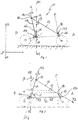
- FIG. 1 assuming, only for ease of description and without limitation to, a reference set of three mutually orthogonal directions, respectively, longitudinal X-X for the length and, in use, parallel to the resting surface of a two-wheeled vehicle, vertical Z-Z for the height and transverse Y-Y for the width of the frame, as well as a front part A corresponding to that part of the frame which, in use, corresponds to the front wheel of a two-wheeled vehicle and a rear part P facing the previous one.
- the frame 10 substantially looks like an "inverted V" with a first rear arm 11 and a second front arm 12 departing from a intersection portion or common upper vertex 13 (hereinafter referred to, without thereby losing its generality, the as vertex 13).
- the ends 11a,12a of the arms 11,12, facing those of the vertex 13, are therefore located at a lower level than the one of the vertex 13 itself in the vertical direction Z-Z.
- the first arm 11 is intended to support and discharge to the ground at least part of a vertical load weighing on the saddle 110 (which is connected to the first 11 or to the second arm 12).
- first 11 and the second arm 12 are arranged so that a vertical load applied by the user to the saddle 110 is divided between the two arms, discharging the weight to the ground (through the wheels 131 and 132).
- the second arm 12 (or one of its direction of extension/elongation) makes an angle of 40° to 70° with respect to an axis Z1-Z1 parallel to the vertical direction Z-Z and passing through the end 11a of the first arm 11 facing the vertex 13.
- the first arm 11 makes an angle ⁇ with said vertical axis Z1-Z1 parallel to the vertical direction Z-Z and passing through the end 11a of the first arm itself, facing those of the vertex 13; said angle ⁇ ranges from a negative value -20° ( fig.1 ), at which the first arm 11 is tilted toward the rear part P with respect to the vertical axis Z1-Z1, so as to bring the vertex 13 in a rear position, in the longitudinal direction X-X, with respect to the end 11a facing the vertex 13 of the first arm 11; to a positive value of 20° ( fig. 2 ), at which the arm 11 is tilted toward the front part A so as to bring the vertex 13 in front position in the longitudinal direction X-X with respect to the end 11a facing the vertex 13 itself.
- the second arm 12 makes an angle ⁇ with the same axis Z1-Z1; the angle ⁇ is preferably of 40° to 70°.
- the angle ⁇ is formed between the direction of extension of the second arm 12 and said vertical axis Z1-Z1 passing through the end 11a of the first arm 11.
- the end 11a facing the vertex 13 of the first arm 11 is integral with a rotation axis 16 parallel to the transverse axis Y-Y; preferably, said rotation axis is implemented by a tube 16a, whose function will hereinafter be more evident.
- the end 11b of the first arm 11 placed at the vertex 13 is extended beyond the vertex with a section 11c of the arm, whose free end will be suitable to be coupled to the saddle 110 of the two-wheeled vehicle, as described below.
- the length of the extended section 11c may be adjusted, for example telescopically or likewise.
- the end 12b of the second arm 12 placed at the vertex 13 could be the one which is extended beyond the vertex with a section of the arm whose free is suitable to be coupled to the saddle 110.
- the saddle 110 is placed on the extension of the first 11 or the second arm 12 beyond the vertex 13, not on the appendixes of the arms located between the two ends 11a, 11b, 12a, 12b.
- the end 12a of the second arm 12 facing the vertex 13 is coupled to a tube 14 with a substantially vertical axis, or with a slight tilt toward the vertex 13 of the "inverted V"; also in this case the use of the tube will be evident in relation to the two-wheeled vehicle of the present invention.
- the tube 14 i.e., the steering axle
- the tube 14 is tilted with respect to the second arm 12, so as to define an angle with it on the longitudinal-vertical plane X-Z.
- the tube 14 is not coaxial with the second arm 12.
- a further embodiment of the frame according to the invention that comprises a tie rod 15 for connecting the arms 11,12 of the inverted V, preferably between the two ends 11a, 12a.
- the tie rod 15, preferably in the form of wire/cable connects the two arms 11, 12 through the fork arm 130; in other words, the tie rod 15 connects the fork arm 130 with the second arm 12.
- the tie rod 15 will be substantially parallel to the longitudinal direction X-X and/or tilted with respect to the same axis X-X by an angle ⁇ of -30° to +30°.
- the tilt with a positive value of ⁇ between the first arm 11 and the vertical direction Z1-Z1 takes the vertex 13 in a forward position toward the front part with respect to the opposite end 11a; this results in an advantageous decomposition of the forces exerted on the frame when it is part of a vehicle, e.g., a two-wheeled one; actually, with reference to fig.2 , where the parts of the vehicle are indicated with dashed lines, it is noted that the saddle 1 of the vehicle is arranged in a longitudinal position between the horizontal rear tube 16 and the vertical front tube 14, i.e., between the pedal shaft and the axle of the front wheel of the vehicle; the force F due to the pedalling user's weight and movements therefore is decomposed according to a first component F1 acting on the first arm 11 and a second component F2 acting along the second arm 12.
- the forward tilt of the arm 11, which connects the saddle 1 to the centre of pedal shaft 16 is completely unconventional.
- This tilt in addition to allowing the realization of a stable and efficient support structure from a structural point of view, provides a disposition of the passenger's body during the movement which is less crouched and advantageously brings the centre of gravity of the user in a position between the two ends 11a, 12aof the arms 11,12.
- the position is similar to the so-called "out of the saddle", which is employed by cyclists to have more power while riding uphill.
- the more linear position of the body although marginally less efficient from the point of view of propulsion, is suitable for a tourist use, since the back, when is less bent, is more relaxed.
- the saddle with this posture should preferably be anatomic, in order not to stress the central pubic area.
- the optimal value of the angle ⁇ takes into account the structural efficiency (distribution of the loads on the arms), including the connection part with the rear wheel, so that the centre of gravity of the passenger vehicle system remains longitudinally between the two supports of the wheels.
- the tilt of the arm 12 is a function of the general size of the bicycle, and the more it is tilted (small ⁇ ), the higher the structural efficiency will be. An advantage is provided also by the folding linkage, as explained hereinafter.
- the tilt of the tie rod 15 essentially depends on the size of the structure, and is basically horizontal.
- the folding frame according to the invention provides that the coupling between the second arm 12 and the first arm 11 at the vertex 13 of the V is implemented by means of a first horizontal (transverse) axis joint/hinge 17, so as to allow the relative rotation for the folding of the frame in order to reduce the overall size ( figs.9a,9b ).
- the coupling between the end 12a of the second arm 12 facing the vertex 13 and the corresponding vertical axis tube 14 is implemented by means of a second transverse axis joint 18, which allows the relative rotation of the front tube 14 with respect to the arm 12, for the folding of the steering axle inserted in the tube 14 when the frame is part of a two-wheeled vehicle ( figs. 9A, 9b ).
- the joint 18 could also a vertical axis one (or anyway lying on the vertical-longitudinal plane).
- both the joint 17 at the vertex 13 of the V and the joint 18 of the other end are expected to comprise a mechanical stop to prevent the convex angle between the respective connected elements from opening beyond a certain value, as well as with a safety lock intended to prevent the accidental closure of the frame when not required. It is understood that the values of ⁇ and ⁇ specified above are to be assessed when the frame is open.
- a rigid element 115 e.g., a tubular one ( fig. 4 ), which has a transverse axis hinge 115a enabling its folding;
- the tie rod may be implemented by a wire 15 ( fig. 5 ), e.g., made of steel, which is kept in tension by said components F1, F2 of the force F, but can be easily folded in the absence of these forces.
- a wire 15 fig. 5
- the tie rod may be implemented by a wire 15 ( fig. 5 ), e.g., made of steel, which is kept in tension by said components F1, F2 of the force F, but can be easily folded in the absence of these forces.
- the vehicle comprises:
- a mechanical stop 135 against a part of the arm 11 is provided ( fig.8 ) .
- an elastic element may be inserted to soften the accelerations which may be transmitted to the passenger when seated.
- the fork arm 130 rigidly extends between a transverse rotation axis of the pedals 120 and a transverse rotation axis of the rear wheel 131.
- the distance between the two axes stays thus unchanged regardless of the open or folded condition of the frame 1.
- This fork arm 130 can be pivoted to the end 11a of the first arm 11, as described and illustrated above, or rigidly connected thereto.
- the fork arm 130 is connected to one of its ends, defined by the pedal shaft 120, at the end 11a of the first arm 11.
- this fork arm 130 might be connected to the end 11a of the first arm 11 with its own intermediate portion, arranged between the pedal shaft 120 and the axle of the rear wheel 131. + a handlebar 140 integral with one end of a steering arm 141 coaxially inserted into the front vertical axis tube 14 beyond which it extends to end with an end fork 142 supporting the front wheel 132.
- the steering arm 141 comprises a transverse joint 141a placed between the tube 14 and the handlebar 140, preferably near said tube 14.
- This transverse joint 141a has also at least one stop and fastening means. Such means allow to limit the tilt of the steering arm 141 and, preferably, to block its position respectively in an operative position, coaxial with the steering axle, and in a folded position, tilted with respect to the steering axle toward the second arm 12.
- the steering arm 141 is substantially parallel to (or, anyway, alongside) the second arm 12.
- transverse joint 141a is preferably alternate, but optionally complementary to the joint 18 located between the steering tube 14 and the second arm 12.
- the motion transmission between the pedal shaft and the rear wheel is expected to comprise a group composed of a disc or chainring 161, coaxial with the pedal shaft 120, a pulley 162 and a flexible transmission element 163, belt or chain.
- the placement between the frame and the pulley transmission mechanism provides that they lie on staggered planes along the transverse axis Y-Y.
- the pedal shaft transmits the rotary motion to the chainring preferably via direct connection, these being integrally connected.
- the metric development i.e., the distance travelled as a result of a complete revolution of the pedals, must be useful to employ; the metric development in this vehicle is obtained by suitably sizing the diameters of the three rotary elements involved in the motion transmission between the pedal and the rear wheel; correspondingly, the diameter of the chainring is substantially greater than that of the pulley.
- a less unbalanced ratio between the two diameters may anyway be achieved by interposing a coaxial reducer between the pedal shaft and the chainring axle.
- the transmission ratio is made variable by means of a derailleur gear able to commute the chain or belt on pulleys of different diameters.
- Figs. 9a and 9b illustrate the folding sequence according to which the various joints/hinges are unlocked and the movable arms of the V rotate around the transverse rotation axes of the joints/hinges in order to have the frame and the vehicle folded along the longitudinal axis of the arms of the V.
- tie rod 15 with the flexible wire which is pending and may be wrapped up or bent is not evident, while in the case of the rigid tie rod 115, shown in figure 9a as partially bent, it remains folded inside and is not visible in figure 9b .
- the folding is thus very easy and intuitive and can be carried out up to a substantial alignment of the two arms 11,12 of the frame; the particular placement between the frame and the pulley transmission linkage, which are on staggered planes, also avoids relative interferences which would increase the transverse thickness (Y-Y) of the folded vehicle.
- the rear wheel can retract with respect to the road position.
- the retraction of the rear wheel takes place by rotating the fork around the pedal shaft on which it can be hinged.
- the frame according to the invention allows to provide a solution to the problems of the prior art, especially proving to be suitable to determine: an improved distribution of the forces exerted on the frame itself; an easy folding for a substantial reduction in the size so as to allow its transportation by different means of transport, as well as an overall reduction of the weights that facilitates the handling and transportation of the vehicle equipped with the said frame.
- the vehicle In the folded position the vehicle can be easily transported by dragging it by hand with the aid of the resting front wheel, which is located in a lower position with respect to the folded body.
Landscapes
- Engineering & Computer Science (AREA)
- Mechanical Engineering (AREA)
- Automatic Cycles, And Cycles In General (AREA)
Claims (12)
- Châssis pliable pour véhicule doté d'au moins deux essieux de roue (13,132), s'étendant le long d'un ensemble de trois directions réciproquement orthogonales, respectivement longitudinale (X-X) pour la longueur, verticale (Z-Z) pour la hauteur, et transversale (Y-Y) pour la largeur, lesdits essieux de roue étant parallèles à la direction transversale (Y;Y) ; ledit châssis prenant la forme de « V inversé » sur un plan longitudinal-vertical (X-Z) défini par la direction longitudinale (X-X) de la longueur et par la direction verticale (Z-Z) de la hauteur du châssis (10), et comprenant un premier bras arrière (11) et un second bras avant (12) fusionnés dans une partie d'intersection supérieure (13), les extrémités (11a, 12a) des bras (11, 12), faisant face à la partie d'intersection supérieure (13), étant disposées, pendant l'utilisation, à un niveau inférieur par rapport à celui de la partie d'intersection (13) dans la direction verticale (Z-Z), étant l'extrémité (12a) du second bras (12) couplée à un tube de commande avant (14) doté d'un axe incliné par rapport audit second bras (12) de façon à définir un angle avec celui-ci sur le plan longitudinal-vertical (X-Z) ;dans lequel un premier (17) joint d'axe transversal est placé sur la partie d'intersection (13) des deux bras (11, 12)et dans lequel le premier (11) ou le second bras (12) a une extension au-delà de la partie d'intersection (13) définie par une section (11c) du bras dont l'extrémité libre est couplée à une selle (110) du véhicule,et dans lequel le premier bras (11) est destiné à supporter et décharger au sol au moins une partie d'un poids vertical pesant sur la selle (110).
- Châssis pliable selon la revendication 1, caractérisé en ce que, dans une configuration d'utilisation, la direction d'extension du second bras (12) forme un angle β compris entre 40° et 70° par rapport à un axe (Z1-Z1) parallèle à la direction verticale (Z-Z) et passant à travers l'extrémité (11a) du premier bras faisant face à la partie d'intersection (13).
- Véhicule doté d'au moins deux essieux de roue (131, 132), s'étendant le long d'un ensemble de trois directions réciproquement orthogonales, respectivement longitudinale (X-X) pour la longueur, verticale (Z-Z) pour la hauteur et transversale (Y-Y) pour la largeur, lesdits essieux de roue étant parallèles à la direction transversale (Y-Y), comprenant :- au moins une roue avant (132) et au moins une roue arrière (131) ;- un châssis pliable selon la revendication 1 ou 2, dans lequel ledit axe du tube de commande avant (14) est sensiblement vertical ou doté d'une légère inclinaison vers la partie d'intersection (13) du « V inversé » ;- un bras de fourche arrière (130) s'étendant de manière rigide entre un axe de rotation transversal des pédales (120) et un axe de rotation transversal de la roue arrière (131), dans lequel ledit bras de fourche (130) est relié de manière rigide à ou pivoté sur l'extrémité (11a) du premier bras,- un bras de direction (141) inséré de manière pivotante dans ledit tube de commande (14) et associé à ladite roue avant (131).
- Véhicule selon la revendication 3, dans lequel la direction d'extension du second bras (12) forme un angle β compris entre 40° et 70° par rapport à un axe (Z1-Z1) parallèle à la direction verticale (Z-Z) et passant à travers l'extrémité (11a) du premier bras faisant face à la partie d'intersection (13) .
- Véhicule selon la revendication 3 ou 4, dans lequel le premier bras arrière (11) forme un angle α compris entre -20° et +20° par rapport à un axe (Z1-Z1) parallèle à la direction verticale (Z-Z) et passant à travers l'extrémité (11a) du premier bras faisant face à la partie d'intersection (13).
- Véhicule selon l'une quelconque des revendications précédentes 3 à 5, caractérisé en ce que le couplage entre l'extrémité (12a) faisant face au sommet (13) du second bras (12) et le tube avant (14) comprend un joint d'axe transversal (18) pour la rotation relative du tube (14) par rapport au second bras (12).
- Véhicule selon l'une quelconque des revendications précédentes 3 à 6, caractérisé en ce que le bras de direction (141) s'étend entre un guidon (140) et une fourche d'extrémité (142) passant à travers le tube (14) ; ledit bras de direction (141) comprenant un joint transversal (141a) placé entre le tube (14) et le guidon (14), préférablement près dudit tube (14).
- Véhicule selon l'une quelconque des revendications précédentes 3 à 7, caractérisé en ce qu'il comprend une barre d'accouplement (15; 115) pour relier les bras (11, 12) du V inversé et/ou du bras de fourche (130) au second bras (12).
- Véhicule selon la revendication 8, caractérisé en ce que ladite barre d'accouplement (15) est mise en œuvre par un élément rigide (115) ou un fil (15).
- Véhicule selon l'une quelconque des revendications précédentes 3 à 9, caractérisé en ce que l'axe de rotation transversal des pédales (120) est inséré dans un tube d'axe transversal (16) situé à l'extrémité avant du bras de fourche (130).
- Véhicule selon la revendication 10, caractérisé en ce que ledit tube (16) est placé à l'extrémité (11a) du premier bras (11).
- Véhicule selon l'une quelconque des revendications précédentes 3 à 11, caractérisé en ce qu'il comprend une butée mécanique (135) interposée de manière opérationnelle entre ledit bras de fourche (130) et ledit premier bras (11) afin de maintenir le bras de fourche (130) en place lorsque la bicyclette est en mouvement.
Priority Applications (1)
| Application Number | Priority Date | Filing Date | Title |
|---|---|---|---|
| SM20220020T SMT202200020T1 (it) | 2016-12-28 | 2017-12-28 | Telaio pre veicolo ad almeno due assi-ruota e veicolo a due assi-ruota comprendente telaio |
Applications Claiming Priority (2)
| Application Number | Priority Date | Filing Date | Title |
|---|---|---|---|
| IT102016000131589A IT201600131589A1 (it) | 2016-12-28 | 2016-12-28 | Telaio pieghevole a v rovesciata per veicoli ad almeno due assi ruote e veicolo pieghevole ad almeno due assi ruote dotato di tale telaio |
| PCT/IB2017/058451 WO2018122753A1 (fr) | 2016-12-28 | 2017-12-28 | Châssis pour véhicule doté d'au moins deux essieux de roue et véhicule doté de deux essieux de roue comprenant le châssis |
Publications (2)
| Publication Number | Publication Date |
|---|---|
| EP3562736A1 EP3562736A1 (fr) | 2019-11-06 |
| EP3562736B1 true EP3562736B1 (fr) | 2021-11-24 |
Family
ID=58670248
Family Applications (1)
| Application Number | Title | Priority Date | Filing Date |
|---|---|---|---|
| EP17835506.1A Not-in-force EP3562736B1 (fr) | 2016-12-28 | 2017-12-28 | Châssis pour véhicule doté d'au moins deux essieux de roue et véhicule doté de deux essieux de roue comprenant le châssis |
Country Status (5)
| Country | Link |
|---|---|
| EP (1) | EP3562736B1 (fr) |
| DK (1) | DK3562736T3 (fr) |
| IT (1) | IT201600131589A1 (fr) |
| SM (1) | SMT202200020T1 (fr) |
| WO (1) | WO2018122753A1 (fr) |
Family Cites Families (7)
| Publication number | Priority date | Publication date | Assignee | Title |
|---|---|---|---|---|
| GB8505070D0 (en) * | 1985-02-27 | 1985-03-27 | Sanders M A | Folding/demountable bicycles |
| GB2309015B (en) * | 1996-01-15 | 1999-10-27 | John Colin Lees | Folding bicycle |
| IT1299007B1 (it) * | 1998-04-02 | 2000-02-07 | Francesco Mombelli | Bicicletta compattabile nel volume delle due ruote affiancate |
| DE10229698A1 (de) * | 2002-07-02 | 2004-01-29 | Martin Hoerdum | Faltrad |
| US20080303243A1 (en) * | 2007-06-08 | 2008-12-11 | Francis Ying | Collapsible bicycle frame |
| US20100066054A1 (en) * | 2008-09-18 | 2010-03-18 | I-Huang Chen | Collapsible bicycle |
| CN105172964B (zh) * | 2015-08-04 | 2017-11-17 | 石美秀 | 一种高强度折叠自行车 |
-
2016
- 2016-12-28 IT IT102016000131589A patent/IT201600131589A1/it unknown
-
2017
- 2017-12-28 DK DK17835506.1T patent/DK3562736T3/da active
- 2017-12-28 WO PCT/IB2017/058451 patent/WO2018122753A1/fr not_active Ceased
- 2017-12-28 SM SM20220020T patent/SMT202200020T1/it unknown
- 2017-12-28 EP EP17835506.1A patent/EP3562736B1/fr not_active Not-in-force
Also Published As
| Publication number | Publication date |
|---|---|
| SMT202200020T1 (it) | 2022-03-21 |
| EP3562736A1 (fr) | 2019-11-06 |
| IT201600131589A1 (it) | 2018-06-28 |
| WO2018122753A1 (fr) | 2018-07-05 |
| DK3562736T3 (da) | 2022-01-31 |
Similar Documents
| Publication | Publication Date | Title |
|---|---|---|
| KR100646019B1 (ko) | 접철식 자전거 | |
| US8123243B2 (en) | Foldable bicycle | |
| CN100513246C (zh) | 包含可折叠区域的人力驱动地面交通工具 | |
| HK1215801A1 (zh) | 具有单框架铰链的紧凑型折叠自行车 | |
| US6286848B1 (en) | Two-wheeled folding bicycle | |
| US5342074A (en) | Dual recumbent vehicle | |
| WO2014083481A1 (fr) | Véhicule à pédale | |
| US20180127049A1 (en) | Collapsible flip-pivot bicycle | |
| EP3562736B1 (fr) | Châssis pour véhicule doté d'au moins deux essieux de roue et véhicule doté de deux essieux de roue comprenant le châssis | |
| KR100920263B1 (ko) | 접철식 자전거 | |
| RU2391244C1 (ru) | Велосипед | |
| CN109927833B (zh) | 可折叠自行车 | |
| RU2161577C1 (ru) | Велоколяска | |
| RU226830U1 (ru) | Складной велосипед | |
| CN219601531U (zh) | 一种特快自行车赛车 | |
| CN208947502U (zh) | 多功能自行车 | |
| CN209833874U (zh) | 自行车折收机构 | |
| JP2020147151A (ja) | 3輪自転車 | |
| Hon | Folding bicycles: A treatise | |
| CN120621559A (zh) | 一种双人的前驱后转向自行车 | |
| JP3168709U (ja) | タンデム自転車の改良構造 | |
| SI21365A (sl) | Sklopljivo kolo | |
| KR20110113789A (ko) | 중륜 구동 자전거 | |
| CN100387479C (zh) | 一种中轴前置坐式三轮车及其车架 | |
| IT202000027339A1 (it) | Monopattino richiudibile a telaio tubolare curvo |
Legal Events
| Date | Code | Title | Description |
|---|---|---|---|
| STAA | Information on the status of an ep patent application or granted ep patent |
Free format text: STATUS: UNKNOWN |
|
| STAA | Information on the status of an ep patent application or granted ep patent |
Free format text: STATUS: THE INTERNATIONAL PUBLICATION HAS BEEN MADE |
|
| PUAI | Public reference made under article 153(3) epc to a published international application that has entered the european phase |
Free format text: ORIGINAL CODE: 0009012 |
|
| STAA | Information on the status of an ep patent application or granted ep patent |
Free format text: STATUS: REQUEST FOR EXAMINATION WAS MADE |
|
| 17P | Request for examination filed |
Effective date: 20190717 |
|
| AK | Designated contracting states |
Kind code of ref document: A1 Designated state(s): AL AT BE BG CH CY CZ DE DK EE ES FI FR GB GR HR HU IE IS IT LI LT LU LV MC MK MT NL NO PL PT RO RS SE SI SK SM TR |
|
| AX | Request for extension of the european patent |
Extension state: BA ME |
|
| DAV | Request for validation of the european patent (deleted) | ||
| DAX | Request for extension of the european patent (deleted) | ||
| GRAP | Despatch of communication of intention to grant a patent |
Free format text: ORIGINAL CODE: EPIDOSNIGR1 |
|
| STAA | Information on the status of an ep patent application or granted ep patent |
Free format text: STATUS: GRANT OF PATENT IS INTENDED |
|
| INTG | Intention to grant announced |
Effective date: 20210902 |
|
| GRAS | Grant fee paid |
Free format text: ORIGINAL CODE: EPIDOSNIGR3 |
|
| GRAA | (expected) grant |
Free format text: ORIGINAL CODE: 0009210 |
|
| STAA | Information on the status of an ep patent application or granted ep patent |
Free format text: STATUS: THE PATENT HAS BEEN GRANTED |
|
| RAP1 | Party data changed (applicant data changed or rights of an application transferred) |
Owner name: HENJOY S.R.L. |
|
| RIN1 | Information on inventor provided before grant (corrected) |
Inventor name: BERTIN, DANIELE MARIA |
|
| AK | Designated contracting states |
Kind code of ref document: B1 Designated state(s): AL AT BE BG CH CY CZ DE DK EE ES FI FR GB GR HR HU IE IS IT LI LT LU LV MC MK MT NL NO PL PT RO RS SE SI SK SM TR |
|
| REG | Reference to a national code |
Ref country code: GB Ref legal event code: FG4D |
|
| REG | Reference to a national code |
Ref country code: AT Ref legal event code: REF Ref document number: 1449669 Country of ref document: AT Kind code of ref document: T Effective date: 20211215 |
|
| REG | Reference to a national code |
Ref country code: DE Ref legal event code: R096 Ref document number: 602017049935 Country of ref document: DE |
|
| REG | Reference to a national code |
Ref country code: IE Ref legal event code: FG4D |
|
| REG | Reference to a national code |
Ref country code: DK Ref legal event code: T3 Effective date: 20220127 |
|
| REG | Reference to a national code |
Ref country code: SE Ref legal event code: TRGR |
|
| REG | Reference to a national code |
Ref country code: NL Ref legal event code: FP |
|
| REG | Reference to a national code |
Ref country code: LT Ref legal event code: MG9D |
|
| REG | Reference to a national code |
Ref country code: AT Ref legal event code: MK05 Ref document number: 1449669 Country of ref document: AT Kind code of ref document: T Effective date: 20211124 |
|
| PG25 | Lapsed in a contracting state [announced via postgrant information from national office to epo] |
Ref country code: RS Free format text: LAPSE BECAUSE OF FAILURE TO SUBMIT A TRANSLATION OF THE DESCRIPTION OR TO PAY THE FEE WITHIN THE PRESCRIBED TIME-LIMIT Effective date: 20211124 Ref country code: LT Free format text: LAPSE BECAUSE OF FAILURE TO SUBMIT A TRANSLATION OF THE DESCRIPTION OR TO PAY THE FEE WITHIN THE PRESCRIBED TIME-LIMIT Effective date: 20211124 Ref country code: FI Free format text: LAPSE BECAUSE OF FAILURE TO SUBMIT A TRANSLATION OF THE DESCRIPTION OR TO PAY THE FEE WITHIN THE PRESCRIBED TIME-LIMIT Effective date: 20211124 Ref country code: BG Free format text: LAPSE BECAUSE OF FAILURE TO SUBMIT A TRANSLATION OF THE DESCRIPTION OR TO PAY THE FEE WITHIN THE PRESCRIBED TIME-LIMIT Effective date: 20220224 Ref country code: AT Free format text: LAPSE BECAUSE OF FAILURE TO SUBMIT A TRANSLATION OF THE DESCRIPTION OR TO PAY THE FEE WITHIN THE PRESCRIBED TIME-LIMIT Effective date: 20211124 |
|
| PG25 | Lapsed in a contracting state [announced via postgrant information from national office to epo] |
Ref country code: IS Free format text: LAPSE BECAUSE OF FAILURE TO SUBMIT A TRANSLATION OF THE DESCRIPTION OR TO PAY THE FEE WITHIN THE PRESCRIBED TIME-LIMIT Effective date: 20220324 Ref country code: PT Free format text: LAPSE BECAUSE OF FAILURE TO SUBMIT A TRANSLATION OF THE DESCRIPTION OR TO PAY THE FEE WITHIN THE PRESCRIBED TIME-LIMIT Effective date: 20220324 Ref country code: PL Free format text: LAPSE BECAUSE OF FAILURE TO SUBMIT A TRANSLATION OF THE DESCRIPTION OR TO PAY THE FEE WITHIN THE PRESCRIBED TIME-LIMIT Effective date: 20211124 Ref country code: NO Free format text: LAPSE BECAUSE OF FAILURE TO SUBMIT A TRANSLATION OF THE DESCRIPTION OR TO PAY THE FEE WITHIN THE PRESCRIBED TIME-LIMIT Effective date: 20220224 Ref country code: LV Free format text: LAPSE BECAUSE OF FAILURE TO SUBMIT A TRANSLATION OF THE DESCRIPTION OR TO PAY THE FEE WITHIN THE PRESCRIBED TIME-LIMIT Effective date: 20211124 Ref country code: HR Free format text: LAPSE BECAUSE OF FAILURE TO SUBMIT A TRANSLATION OF THE DESCRIPTION OR TO PAY THE FEE WITHIN THE PRESCRIBED TIME-LIMIT Effective date: 20211124 Ref country code: GR Free format text: LAPSE BECAUSE OF FAILURE TO SUBMIT A TRANSLATION OF THE DESCRIPTION OR TO PAY THE FEE WITHIN THE PRESCRIBED TIME-LIMIT Effective date: 20220225 Ref country code: ES Free format text: LAPSE BECAUSE OF FAILURE TO SUBMIT A TRANSLATION OF THE DESCRIPTION OR TO PAY THE FEE WITHIN THE PRESCRIBED TIME-LIMIT Effective date: 20211124 |
|
| PG25 | Lapsed in a contracting state [announced via postgrant information from national office to epo] |
Ref country code: SK Free format text: LAPSE BECAUSE OF FAILURE TO SUBMIT A TRANSLATION OF THE DESCRIPTION OR TO PAY THE FEE WITHIN THE PRESCRIBED TIME-LIMIT Effective date: 20211124 Ref country code: RO Free format text: LAPSE BECAUSE OF FAILURE TO SUBMIT A TRANSLATION OF THE DESCRIPTION OR TO PAY THE FEE WITHIN THE PRESCRIBED TIME-LIMIT Effective date: 20211124 Ref country code: EE Free format text: LAPSE BECAUSE OF FAILURE TO SUBMIT A TRANSLATION OF THE DESCRIPTION OR TO PAY THE FEE WITHIN THE PRESCRIBED TIME-LIMIT Effective date: 20211124 Ref country code: CZ Free format text: LAPSE BECAUSE OF FAILURE TO SUBMIT A TRANSLATION OF THE DESCRIPTION OR TO PAY THE FEE WITHIN THE PRESCRIBED TIME-LIMIT Effective date: 20211124 |
|
| REG | Reference to a national code |
Ref country code: CH Ref legal event code: PL |
|
| REG | Reference to a national code |
Ref country code: DE Ref legal event code: R097 Ref document number: 602017049935 Country of ref document: DE |
|
| PG25 | Lapsed in a contracting state [announced via postgrant information from national office to epo] |
Ref country code: MC Free format text: LAPSE BECAUSE OF FAILURE TO SUBMIT A TRANSLATION OF THE DESCRIPTION OR TO PAY THE FEE WITHIN THE PRESCRIBED TIME-LIMIT Effective date: 20211124 |
|
| REG | Reference to a national code |
Ref country code: BE Ref legal event code: MM Effective date: 20211231 |
|
| PLBE | No opposition filed within time limit |
Free format text: ORIGINAL CODE: 0009261 |
|
| STAA | Information on the status of an ep patent application or granted ep patent |
Free format text: STATUS: NO OPPOSITION FILED WITHIN TIME LIMIT |
|
| PG25 | Lapsed in a contracting state [announced via postgrant information from national office to epo] |
Ref country code: LU Free format text: LAPSE BECAUSE OF NON-PAYMENT OF DUE FEES Effective date: 20211228 Ref country code: IE Free format text: LAPSE BECAUSE OF NON-PAYMENT OF DUE FEES Effective date: 20211228 Ref country code: AL Free format text: LAPSE BECAUSE OF FAILURE TO SUBMIT A TRANSLATION OF THE DESCRIPTION OR TO PAY THE FEE WITHIN THE PRESCRIBED TIME-LIMIT Effective date: 20211124 |
|
| 26N | No opposition filed |
Effective date: 20220825 |
|
| PG25 | Lapsed in a contracting state [announced via postgrant information from national office to epo] |
Ref country code: SI Free format text: LAPSE BECAUSE OF FAILURE TO SUBMIT A TRANSLATION OF THE DESCRIPTION OR TO PAY THE FEE WITHIN THE PRESCRIBED TIME-LIMIT Effective date: 20211124 Ref country code: BE Free format text: LAPSE BECAUSE OF NON-PAYMENT OF DUE FEES Effective date: 20211231 |
|
| PG25 | Lapsed in a contracting state [announced via postgrant information from national office to epo] |
Ref country code: LI Free format text: LAPSE BECAUSE OF NON-PAYMENT OF DUE FEES Effective date: 20211231 Ref country code: CH Free format text: LAPSE BECAUSE OF NON-PAYMENT OF DUE FEES Effective date: 20211231 |
|
| PG25 | Lapsed in a contracting state [announced via postgrant information from national office to epo] |
Ref country code: CY Free format text: LAPSE BECAUSE OF FAILURE TO SUBMIT A TRANSLATION OF THE DESCRIPTION OR TO PAY THE FEE WITHIN THE PRESCRIBED TIME-LIMIT Effective date: 20211124 |
|
| PG25 | Lapsed in a contracting state [announced via postgrant information from national office to epo] |
Ref country code: HU Free format text: LAPSE BECAUSE OF FAILURE TO SUBMIT A TRANSLATION OF THE DESCRIPTION OR TO PAY THE FEE WITHIN THE PRESCRIBED TIME-LIMIT; INVALID AB INITIO Effective date: 20171228 |
|
| PGFP | Annual fee paid to national office [announced via postgrant information from national office to epo] |
Ref country code: GB Payment date: 20231229 Year of fee payment: 7 |
|
| PGFP | Annual fee paid to national office [announced via postgrant information from national office to epo] |
Ref country code: SM Payment date: 20231227 Year of fee payment: 7 Ref country code: SE Payment date: 20231229 Year of fee payment: 7 Ref country code: NL Payment date: 20231228 Year of fee payment: 7 Ref country code: IT Payment date: 20231229 Year of fee payment: 7 Ref country code: FR Payment date: 20231229 Year of fee payment: 7 Ref country code: DK Payment date: 20231229 Year of fee payment: 7 |
|
| PG25 | Lapsed in a contracting state [announced via postgrant information from national office to epo] |
Ref country code: MK Free format text: LAPSE BECAUSE OF FAILURE TO SUBMIT A TRANSLATION OF THE DESCRIPTION OR TO PAY THE FEE WITHIN THE PRESCRIBED TIME-LIMIT Effective date: 20211124 |
|
| PGFP | Annual fee paid to national office [announced via postgrant information from national office to epo] |
Ref country code: DE Payment date: 20231228 Year of fee payment: 7 |
|
| PG25 | Lapsed in a contracting state [announced via postgrant information from national office to epo] |
Ref country code: MT Free format text: LAPSE BECAUSE OF FAILURE TO SUBMIT A TRANSLATION OF THE DESCRIPTION OR TO PAY THE FEE WITHIN THE PRESCRIBED TIME-LIMIT Effective date: 20211124 |
|
| REG | Reference to a national code |
Ref country code: DE Ref legal event code: R119 Ref document number: 602017049935 Country of ref document: DE |
|
| REG | Reference to a national code |
Ref country code: DK Ref legal event code: EBP Effective date: 20241231 |
|
| REG | Reference to a national code |
Ref country code: SE Ref legal event code: EUG |
|
| REG | Reference to a national code |
Ref country code: NL Ref legal event code: MM Effective date: 20250101 |
|
| GBPC | Gb: european patent ceased through non-payment of renewal fee |
Effective date: 20241228 |
|
| PG25 | Lapsed in a contracting state [announced via postgrant information from national office to epo] |
Ref country code: NL Free format text: LAPSE BECAUSE OF NON-PAYMENT OF DUE FEES Effective date: 20250101 |
|
| PG25 | Lapsed in a contracting state [announced via postgrant information from national office to epo] |
Ref country code: SM Free format text: LAPSE BECAUSE OF NON-PAYMENT OF DUE FEES Effective date: 20250716 |
|
| PG25 | Lapsed in a contracting state [announced via postgrant information from national office to epo] |
Ref country code: DE Free format text: LAPSE BECAUSE OF NON-PAYMENT OF DUE FEES Effective date: 20250701 |
|
| PG25 | Lapsed in a contracting state [announced via postgrant information from national office to epo] |
Ref country code: IT Free format text: LAPSE BECAUSE OF NON-PAYMENT OF DUE FEES Effective date: 20241228 |
|
| PG25 | Lapsed in a contracting state [announced via postgrant information from national office to epo] |
Ref country code: GB Free format text: LAPSE BECAUSE OF NON-PAYMENT OF DUE FEES Effective date: 20241228 |
|
| PG25 | Lapsed in a contracting state [announced via postgrant information from national office to epo] |
Ref country code: FR Free format text: LAPSE BECAUSE OF NON-PAYMENT OF DUE FEES Effective date: 20241231 |
|
| PG25 | Lapsed in a contracting state [announced via postgrant information from national office to epo] |
Ref country code: TR Free format text: LAPSE BECAUSE OF FAILURE TO SUBMIT A TRANSLATION OF THE DESCRIPTION OR TO PAY THE FEE WITHIN THE PRESCRIBED TIME-LIMIT Effective date: 20211124 |
|
| PG25 | Lapsed in a contracting state [announced via postgrant information from national office to epo] |
Ref country code: DK Free format text: LAPSE BECAUSE OF NON-PAYMENT OF DUE FEES Effective date: 20241231 |