EP3563012B1 - Verfahren zur herstellung eines strukturellen trägers - Google Patents
Verfahren zur herstellung eines strukturellen trägers Download PDFInfo
- Publication number
- EP3563012B1 EP3563012B1 EP17825870.3A EP17825870A EP3563012B1 EP 3563012 B1 EP3563012 B1 EP 3563012B1 EP 17825870 A EP17825870 A EP 17825870A EP 3563012 B1 EP3563012 B1 EP 3563012B1
- Authority
- EP
- European Patent Office
- Prior art keywords
- base part
- polymer
- elongate
- elongate reinforcement
- strip
- Prior art date
- Legal status (The legal status is an assumption and is not a legal conclusion. Google has not performed a legal analysis and makes no representation as to the accuracy of the status listed.)
- Active
Links
Images

Classifications
-
- E—FIXED CONSTRUCTIONS
- E04—BUILDING
- E04C—STRUCTURAL ELEMENTS; BUILDING MATERIALS
- E04C3/00—Structural elongated elements designed for load-supporting
- E04C3/02—Joists; Girders, trusses, or trusslike structures, e.g. prefabricated; Lintels; Transoms; Braces
- E04C3/28—Joists; Girders, trusses, or trusslike structures, e.g. prefabricated; Lintels; Transoms; Braces of materials not covered by groups E04C3/04 - E04C3/20
-
- B—PERFORMING OPERATIONS; TRANSPORTING
- B29—WORKING OF PLASTICS; WORKING OF SUBSTANCES IN A PLASTIC STATE IN GENERAL
- B29C—SHAPING OR JOINING OF PLASTICS; SHAPING OF MATERIAL IN A PLASTIC STATE, NOT OTHERWISE PROVIDED FOR; AFTER-TREATMENT OF THE SHAPED PRODUCTS, e.g. REPAIRING
- B29C48/00—Extrusion moulding, i.e. expressing the moulding material through a die or nozzle which imparts the desired form; Apparatus therefor
- B29C48/16—Articles comprising two or more components, e.g. co-extruded layers
- B29C48/18—Articles comprising two or more components, e.g. co-extruded layers the components being layers
- B29C48/21—Articles comprising two or more components, e.g. co-extruded layers the components being layers the layers being joined at their surfaces
-
- B—PERFORMING OPERATIONS; TRANSPORTING
- B29—WORKING OF PLASTICS; WORKING OF SUBSTANCES IN A PLASTIC STATE IN GENERAL
- B29C—SHAPING OR JOINING OF PLASTICS; SHAPING OF MATERIAL IN A PLASTIC STATE, NOT OTHERWISE PROVIDED FOR; AFTER-TREATMENT OF THE SHAPED PRODUCTS, e.g. REPAIRING
- B29C48/00—Extrusion moulding, i.e. expressing the moulding material through a die or nozzle which imparts the desired form; Apparatus therefor
- B29C48/15—Extrusion moulding, i.e. expressing the moulding material through a die or nozzle which imparts the desired form; Apparatus therefor incorporating preformed parts or layers, e.g. extrusion moulding around inserts
-
- B—PERFORMING OPERATIONS; TRANSPORTING
- B29—WORKING OF PLASTICS; WORKING OF SUBSTANCES IN A PLASTIC STATE IN GENERAL
- B29C—SHAPING OR JOINING OF PLASTICS; SHAPING OF MATERIAL IN A PLASTIC STATE, NOT OTHERWISE PROVIDED FOR; AFTER-TREATMENT OF THE SHAPED PRODUCTS, e.g. REPAIRING
- B29C48/00—Extrusion moulding, i.e. expressing the moulding material through a die or nozzle which imparts the desired form; Apparatus therefor
- B29C48/15—Extrusion moulding, i.e. expressing the moulding material through a die or nozzle which imparts the desired form; Apparatus therefor incorporating preformed parts or layers, e.g. extrusion moulding around inserts
- B29C48/154—Coating solid articles, i.e. non-hollow articles
- B29C48/155—Partial coating thereof
-
- B—PERFORMING OPERATIONS; TRANSPORTING
- B29—WORKING OF PLASTICS; WORKING OF SUBSTANCES IN A PLASTIC STATE IN GENERAL
- B29C—SHAPING OR JOINING OF PLASTICS; SHAPING OF MATERIAL IN A PLASTIC STATE, NOT OTHERWISE PROVIDED FOR; AFTER-TREATMENT OF THE SHAPED PRODUCTS, e.g. REPAIRING
- B29C48/00—Extrusion moulding, i.e. expressing the moulding material through a die or nozzle which imparts the desired form; Apparatus therefor
- B29C48/16—Articles comprising two or more components, e.g. co-extruded layers
-
- B—PERFORMING OPERATIONS; TRANSPORTING
- B29—WORKING OF PLASTICS; WORKING OF SUBSTANCES IN A PLASTIC STATE IN GENERAL
- B29C—SHAPING OR JOINING OF PLASTICS; SHAPING OF MATERIAL IN A PLASTIC STATE, NOT OTHERWISE PROVIDED FOR; AFTER-TREATMENT OF THE SHAPED PRODUCTS, e.g. REPAIRING
- B29C48/00—Extrusion moulding, i.e. expressing the moulding material through a die or nozzle which imparts the desired form; Apparatus therefor
- B29C48/25—Component parts, details or accessories; Auxiliary operations
- B29C48/30—Extrusion nozzles or dies
- B29C48/304—Extrusion nozzles or dies specially adapted for bringing together components, e.g. melts within the die
-
- B—PERFORMING OPERATIONS; TRANSPORTING
- B29—WORKING OF PLASTICS; WORKING OF SUBSTANCES IN A PLASTIC STATE IN GENERAL
- B29C—SHAPING OR JOINING OF PLASTICS; SHAPING OF MATERIAL IN A PLASTIC STATE, NOT OTHERWISE PROVIDED FOR; AFTER-TREATMENT OF THE SHAPED PRODUCTS, e.g. REPAIRING
- B29C48/00—Extrusion moulding, i.e. expressing the moulding material through a die or nozzle which imparts the desired form; Apparatus therefor
- B29C48/25—Component parts, details or accessories; Auxiliary operations
- B29C48/30—Extrusion nozzles or dies
- B29C48/32—Extrusion nozzles or dies with annular openings, e.g. for forming tubular articles
- B29C48/34—Cross-head annular extrusion nozzles, i.e. for simultaneously receiving moulding material and the preform to be coated
-
- E—FIXED CONSTRUCTIONS
- E04—BUILDING
- E04C—STRUCTURAL ELEMENTS; BUILDING MATERIALS
- E04C3/00—Structural elongated elements designed for load-supporting
- E04C3/02—Joists; Girders, trusses, or trusslike structures, e.g. prefabricated; Lintels; Transoms; Braces
- E04C3/29—Joists; Girders, trusses, or trusslike structures, e.g. prefabricated; Lintels; Transoms; Braces built-up from parts of different material, i.e. composite structures
-
- B—PERFORMING OPERATIONS; TRANSPORTING
- B29—WORKING OF PLASTICS; WORKING OF SUBSTANCES IN A PLASTIC STATE IN GENERAL
- B29K—INDEXING SCHEME ASSOCIATED WITH SUBCLASSES B29B, B29C OR B29D, RELATING TO MOULDING MATERIALS OR TO MATERIALS FOR MOULDS, REINFORCEMENTS, FILLERS OR PREFORMED PARTS, e.g. INSERTS
- B29K2105/00—Condition, form or state of moulded material or of the material to be shaped
- B29K2105/06—Condition, form or state of moulded material or of the material to be shaped containing reinforcements, fillers or inserts
- B29K2105/08—Condition, form or state of moulded material or of the material to be shaped containing reinforcements, fillers or inserts of continuous length, e.g. cords, rovings, mats, fabrics, strands or yarns
- B29K2105/10—Cords, strands or rovings, e.g. oriented cords, strands or rovings
- B29K2105/101—Oriented
- B29K2105/105—Oriented uni directionally
- B29K2105/106—Oriented uni directionally longitudinally
-
- B—PERFORMING OPERATIONS; TRANSPORTING
- B29—WORKING OF PLASTICS; WORKING OF SUBSTANCES IN A PLASTIC STATE IN GENERAL
- B29L—INDEXING SCHEME ASSOCIATED WITH SUBCLASS B29C, RELATING TO PARTICULAR ARTICLES
- B29L2031/00—Other particular articles
- B29L2031/001—Profiled members, e.g. beams, sections
-
- E—FIXED CONSTRUCTIONS
- E04—BUILDING
- E04C—STRUCTURAL ELEMENTS; BUILDING MATERIALS
- E04C5/00—Reinforcing elements, e.g. for concrete; Auxiliary elements therefor
- E04C5/07—Reinforcing elements of material other than metal, e.g. of glass, of plastics, or not exclusively made of metal
Definitions
- the present teachings relate to a method of manufacturing of a structural beam, and in particular of a structural beam for use as a building structural element, such as a roof beam for supporting the roof of a building, or as a floor beam or wall beam.
- Roof beams such as rafters, purlins and ridge beams, are typically made of timber such as oak, or are made of steel. A requirement for such roof beams is a high bending stiffness. It is cumbersome to place such beams in a building, because of the relatively large weight of such beams.
- US 2004/0062915 A1 relates to a reinforced composite structural member.
- the invention in a first aspect, relates to a method of manufacturing of a structural beam, as defined in claim 1.
- the beam to be manufactured comprises an elongate base part comprising a polymer, the base part having a length, defining a length direction of the beam, and having a width and a height, and an elongate reinforcement part comprising a strip comprising a polymer and unidirectional fibers, bonded to the base part at an outer surface of the base part and extending in the length direction along the length of the base part, the strip having a higher Young's modulus than the base part.
- the method of manufacturing a structural beam according to the present invention comprises
- the base part comprises a composition consisting of the polymer and glass fibers, and/or additives.
- the composition (if used) or the polymer defines the Young's modulus of the base part.
- the elongate base part comprises at least 60 wt.% or at least 70 wt.%, preferably at least 90 wt.% or even 95 wt.% or 100wt.% of said composition (if used) or of said polymer, in other words consists of said composition or said polymer, optionally with additives.
- the composition of the strip comprises or consists of the polymer and the unidirectional fibers. Said composition of the strip defines the Young's modulus of the strip.
- the structural beam manufactured according to the invention is intended to be used such that the beam is loaded with a weight transverse to the surface at which the elongate reinforcement part is provided and such that the elongate reinforcement part is provided at the surface of the beam which, in use, is subject to the highest tensile strain, that means generally at the surface that is the furthest away from the neutral axis of the beam.
- a beam according to the invention would have been provided in a building such that the elongate reinforcement part is at a lower outer surface of the base part of the beam, that beam is intended to be loaded with a vertical, downward force.
- the structural beam manufactured according to the present teachings may have a relatively high bending stiffness, or, resistance to bending, due to the presence of the elongate reinforcement part comprising the unidirectional fibers, the reinforcement part bonded to the base part of the beam, wherein the polymer, or the composition comprising the polymer, of the base part may be low cost, since the strip contributes to the bending strength to a large extent.
- the structural beam according to the present invention may be effectively recycled, it may be made such that it is not sensitive to rot and/or rust and/or mold growth, it may have a longer lifetime, it may be made in any feasible dimension, it may be made such that it is not hygroscopic, i.e. it does not attract water.
- An effect of the strip of the elongate reinforcement part having a higher Young's modulus, or, E-modulus, than the base part is that in use under a bending load, the strain of the base part at the outer surface at which the elongate reinforcement part is provided, is reduced.
- the beam is formed in a very simple and cost efficient manner by means of the extrusion process.
- strip comprising a polymer and unidirectional fibers
- a strip comprising a polymer reinforced with fibers oriented in substantially one direction.
- the fibers are oriented in substantially the length direction.
- Such a strip may for example be produced by impregnating a continuous fiber strand with polymer, for example as described in WO 2016/142784 .
- the strip may have a relatively small amount of fibers oriented in a direction other than the longitudinal direction, such as in transverse, or, width direction of the strip.
- the amount of fibers in the strip may vary along wide ranges, for example between 35 and 85 volume %, preferably between 50 to 75 volume %, preferably 55 to 70 %, based on the total of the polymer and the fibers.
- the strip extending along the length of the base part is meant that the strip extends, continuously, along at least substantially the length of the base part, preferably along at least 75% of said length, further preferably along at least 90% of said length.
- the beam has such an elongate reinforcement part bonded to the base part at two opposite sides, or, outer surfaces, such as a top and a bottom surface, of the base part.
- the structural beam further comprises a further elongate reinforcement part comprising a further strip comprising a polymer and unidirectional fibers, bonded in accordance with the method according to the present teachings to the base part at a further outer surface of the base part opposite the outer surface and extending in the length direction along the length of the base part.
- the further strip thus also having a higher Young's modulus than the base part.
- such a beam would be used as a roof beam such as a purlin, for supporting a roof of a building
- the roof loads the beam downwards. Upward forces are generated by wind forces on the roof.
- the elongate reinforcement part and the further elongate reinforcement part would thus be present on an upper and a lower outer surface, respectively.
- the elongate reinforcement part and/or the further elongate reinforcement part comprise multiple of such strips comprising a polymer and unidirectional fibers bonded to each other.
- the multiple strips form a stack of strips, bonded to the outer and/or further outer surface of the base part.
- the beam may be produced in a more convenient manner, since now each strip may be relatively thin, as the multiple strips in combination will provide the desired bending stiffness, and therefore easily be provided on a roll during production. This holds in particular for strips having a thickness of less than 1 mm.
- the elongate reinforcement part is bonded to the polymer base part while forming the base part by means of extrusion.
- a beam according to the invention is manufactured in a highly efficient manner having a strong bond between the base part and the elongate reinforcement part and optionally the further elongated reinforcement part.
- thermoplastic polymers include polyethylene terephthalate (PET), polycarbonates (PC), polybutylene terephthalate (PBT), poly(l,4-cyclohexylidene cyclohexane-I,4-dicarboxylate) (PCCD), glycol modified polycyclohexyl terephthalate (PCTG), poly(phenylene oxide) (PPO), polypropylene (PP), polyethylene (PE), polyvinyl chloride (PVC), polystyrene (PS), polymethyl methacrylate (PMMA), polyethyleneimine or polyetherimide (PEI) or derivatives thereof, thermoplastic elastomers (TPE), terephthalic acid (TPA) elastomers, poly(cyclohexanedimethylene terephthalate) (
- thermoplastic polymers include polypropylene, polyamides, polyethylene terephthalate, polycarbonates (PC), polybutylene terephthalate, poly(phenylene oxide) (PPO), polyetherimide, polyethylene, co-polymers thereof, or blends thereof.
- thermoplastic polymers include polypropylene, polyethylene, polyamides, polycarbonates (PC), co-polymers thereof, or blends thereof.
- polypropylene examples include but are not limited to homopolymers of propylene, random copolymers of propylene with a C2 or C4 to C10 alpha olefin comonomer, for example ethylene; and heterophasic propylene copolymers comprising a matrix of propylene homopolymer and/or random copolymers of propylene and a dispersed propylene-alpha-olefin rubber phase, wherein the alpha-olefin may be chosen from the list consisting of C2 and C4 to C10 alpha olefin comonomers (multiple comonomers possible).
- polyethylene examples include but are not limited to linear low density polyethylene (LLDPE), low density polyethylene (LDPE), high density polyethylene (HDPE), preferably HDPE.
- LLDPE linear low density polyethylene
- LDPE low density polyethylene
- HDPE high density polyethylene
- the base part comprises a composition consisting of the polymer and fillers and/or additives.
- the strip comprising the polymer and unidirectional fibers may comprise additional fillers and/or additives, in addition to the fibers.
- additional fillers include but are not limited to: steel fibers/ whiskers/ flakes, glass fibers, talc, carbon black, carbon fibers, nanocomposites/ nanofibers.
- Non-limiting examples of additional additives include coupling agents to promote adhesion between the polymeric matrix and continuous fibers, antioxidants, heat stabilizers, flow modifiers, flame retardants, UV stabilizers, UV absorbers, impact modifiers, colorants, or a combination thereof.
- a polymer composition of an above mentioned polymer, and further comprising additives such as for example for fire resistance, UV protection, color, durability, may be provided.
- Suitable strips comprising a polymer and unidirectional fibers, of the elongate reinforcement part, are constituted by unidirectional (UD) fiber-reinforced composites as disclosed in WO 2016/142784 , for example in paragraph [0010].
- UD unidirectional
- Such a fiber-reinforced composite as is known from WO 2016/142784 comprises:
- the beam may be recycled in a more efficient manner, at the end of its life cycle.
- Optimal use of the elongate and further elongate reinforcement parts is achieved because a width of the elongate reinforcement part, and optionally alsothe further elongate reinforcement part, is at least substantially equal to the width of the base part.
- the base part may have been foamed, hollow or solid. If foamed, the foam part may have been coextruded with the remainder of the base part.
- the beam may be further optimized regarding its weight in relation to its stiffness and outer dimensions. An effect of the base part being foamed, including the embodiment that the base part is a hollow profile, filled with a foam, is increased isolation.
- the beam may have structural features such as ribs or flanges, optionally integral with the base part, such as formed by extrusion, for the purpose of connecting the beam to its surrounding structure in use.
- the Young's Modulus of the base part is in the range of 1000 - 15000 N/mm 2 .
- the ratio of the Young's Modulus of the strip to the Young's Modulus of the base part is, in an example, in the range of 2:1 to 40:1, or, in an example, 3:1 to 20:1.
- the strip comprising a polymer and unidirectional fibers may have a thickness in the range of 0.1 - 5 mm, preferably 0.2 - 2.5 mm.
- the base part may have a height in the range of 50 - 700 mm, preferably 100 - 400 mm, and preferably the base part may have a width in the range of 10 - 50 percent of the height.
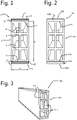
- Figure 1 shows a structural beam 1 for use as a building or civil engineering structural element, such as a roof beam.
- a building or civil engineering structural element such as a roof beam.
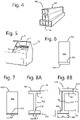
- An example of a manner in which the beam 1, or any other example of a beam manufactured according to the present invention described above and/or below, may be used in practice is shown in figure 5.
- Figure 5 shows part of a building 50.
- a pitched roof of the building is still to be provided.
- a support construction for the roof comprises two roof beams according to the present invention, more specifically purlins 1 as well as a ridge beam 1'.
- the ridge beam 1' may have identical dimensions compared to purlins 1, optionally other than the length thereof, or may have different dimensions. Its height may for example be greater.
- Any of the beams according to the invention may be used as a roof beam such as a mentioned purlin or ridge beam as shown in figure 5 , for example.
- the structural beam 1 as shown in figure 1 has an elongate base part 2 of a polymer.
- the beam has a length of 6 m, at least in the present example, defining a length direction of the beam 1 perpendicular to the plane of the paper.
- the base part has a width w of 100 mm and a height h of 400 mm.
- the base part 2 comprises polypropylene filled with 20 wt.% glass fiber.
- the beam 1 is of rectangular cross section having a height greater than its width. In use the beam 1 is intended to be used such that the beam is mainly subject to forces in the height direction. That means, the resistance to bending is greater in the height direction compared to the width direction.
- the base part 2 is formed as a hollow profile, at least in the present example, having one central, vertical inner rib 8 and two horizontal inner ribs 9.
- one or more cavities of the hollow profile of the base part 2 may be filled such as with a foam such as polypropylene foam.
- the beam 1 has an elongate reinforcement part 3 formed by a multiple, in the present example three, strips 10 comprising a polymer and unidirectional fibers, bonded to the base part 2 at its bottom outer surface 6. More specifically the three strips 10 are bonded to each other so as to form a stack of strips, and are each made of glass filled polypropylene, having a glass fiber content, for example in the range of 35 to 85 volume %.
- the stack of strips forming the elongate reinforcement part 3 extends in the length direction along the entire length of the base part 2. As figure 1 shows, a width of the stack 3 is equal to the width of the base part 2. In another example, the width of the stack may be slightly smaller than the width of the base part.
- the stack may have less or more than three strips, such as 2, 4, 5, 6, 7, 8, 9 or 10 strips, the number depending on parameters such as the material properties and the thickness of individual strips.
- the presence of the elongate reinforcement part 3 on the bottom surface of the base part 2 of the beam 1 increases the bending stiffness, i.e. resistance to bending.
- the beam 1 also has a further elongate reinforcement part 4, also formed by a stack of three strips 10 comprising the same polymer and unidirectional fibers as the strips 10 of stack 3, bonded to the base part at its top outer surface 7.
- the stack of strips 4 extends in the length direction along the length of the base part 2 and is identical to the stack 3. Therefore the above description of stack 3 also applies to stack 4.
- the further elongate reinforcement part 4 may have more or less strips than the elongate reinforcement part 3.
- the strips 10 each have a thickness of 0.5 mm, that means in the direction of the height of the beam 1.
- the elongate reinforcement parts 3 and 4 have been bonded to the polymer base part 2 while forming the base part 2 by means of extrusion, by feeding a polymer composition for forming the base part 2 via an extruder to an extrusion die, and feeding the strips 10 of the elongate reinforcement parts 3 and 4, to the extrusion die, thereby forming the beam 1 while bonding the elongate reinforcement parts 3, 4 to the base part 2 during the forming of the base part 2.
- the polymer composition and the strips 10 are joined so as to bond them together.
- the polymer composition also flows between the individual strips, so as to firmly bond them together, and to the base part. Such a method will be explained below with reference to figures 9a-9c .
- Figure 2 shows a beam 100 which is highly similar to beam 1.
- Beam 100 also has a base part 102, identical to base part 2.
- beam 100 comprises elongate reinforcement parts 103, 104 each formed by a single strip 110 comprising a polymer and unidirectional fibers, bonded to the base part 102 at its bottom outer surface 106 and top outer surface 107, respectively.
- the elongate reinforcement parts 103 and 104 of beam 100 have been bonded to the polymer base part 102 while forming the base part 102 by means of extrusion.
- Figure 3 shows a beam 300 which is identical to beam 100, except for the fact that the cavities of the hollow profile base part 302 are filled with a polyurethane foam 311.
- Figure 4 shows a base part 402 of a beam according to the invention.
- the base part is formed as a hollow profile base part but, other than the rectangular base parts 2, 102 and 302, it has a reversed T-shape cross section.
- At least one of the top outer surface 407 and the lower outer surface 406 of the base part 402 may be provided with an elongate reinforcement part comparable to reinforcement parts 3, 4 ; 103, 104.
- Figure 6 shows a further example of a beam, in the form of a beam 500 having a solid elongate base part 502 of rectangular cross section and, only at its bottom outer surface 506, an elongate reinforcement part 503 formed by a single strip comprising a polymer and unidirectional fibers.
- the strip may have been bonded to the base part by means of extrusion.
- Figure 7 shows a further example of a beam, in the form of a beam 600 having a solid elongate base part 602 of rectangular cross section and, only at its bottom outer surface 606, an elongate reinforcement part 603 formed by a stack of two strips 610 comprising a polymer and unidirectional fibers, bonded to the base part by means of extrusion.
- Figure 8a shows a further example of a beam, in the form of a beam 700 having a solid elongate base part 702 of an I-shaped cross section.
- an elongate reinforcement part 703 formed by a stack of two strips 710 comprising a polymer and unidirectional fibers is provided.
- a further elongate reinforcement part 704 formed by a single strip 710 comprising a polymer and unidirectional fibers is provided. Both the reinforcement parts have been bonded to the base part by means of extrusion.
- Figure 8b shows a further example of a beam, in the form of a beam 800 having a solid elongate base part 802 having, as lower half, an I-shaped cross section, and, as upper half, a reversed L-shaped cross section.
- a elongate reinforcement part 803 formed by a strip comprising a polymer and unidirectional fibers is provided.
- a further elongate reinforcement part 804 formed by a strip comprising a polymer and unidirectional fibers is provided. Both the strips have been bonded to the base part by means of extrusion.
- Figures 9a-9c show an example of an extrusion die 60 for use in a method of manufacturing of the beam 800 according to figure 8b .
- a similar process, using a similar die, adapted to the cross-sectional shape of the base part to be formed and adapted to the requirements as to the reinforcement parts (absent ; single strip ; stack of strips) to be bonded to the top and/or bottom outer surfaces of the base part to be formed, can be used for manufacturing any of the beams according to the invention as discussed throughout the present description, the beams being manufactured in accordance with a method according to the invention.
- the method comprises the steps of feeding a polymer composition, such as (melted) polymer granules, via an extruder (not shown), to the extrusion die 60, via an inlet 61.
- Said polymer composition is used for forming by extrusion the base part 802 of the beam 800.
- two sets of four strips 10 comprising a polymer and unidirectional fibers are fed to the extrusion die 60, each set for forming a stack of strips within the die 60, forming the elongate reinforcement parts 803 and 804 respectively.
- the base part 802 is formed while bonding the elongate reinforcement parts 803, 804, each formed in the extrusion die 60 from four strips 10, to the base part 802 during the forming of the base part 802.
- a feed speed of the strips 10 to the die 60 is set equal to the speed of extrusion.
- the polymer composition also flows between the individual strips of the respective reinforcement parts within the die 60, so as to firmly bond the strips together, and to the base part.
- the beam of the comparative examples had the following characteristics: Width at top (w) 100 mm. Thickness of beam (B1) 4 mm. Height of beam (H1) 296 mm. Width at foot (B3) 100 mm. I (second moment of inertia) 1.32*10 7 mm 4 density of polypropylene A 900 kg/m 3 density of polypropylene A filled with 30wt% glass fiber B 1120 kg/m 3
- reinforcement parts were provided on the exterior and interior side as indicated in Fig 8b .
- the reinforcement parts had the following characteristics: Width (B3) 100 mm.
- the resistance to bending per meter is the resistance to bending divided by the height of the beam (H1).
- the Young's modulus was determined according to ISO527/1B (version as in force as of 1/1/2016).
- the beams manufactured in accordance with a method according to the invention have a significantly increased resistance to bending at the same dimensions.
- the elongate base part comprises in addition to the polymer, also reinforced fibers.
- Example 3 CE 2 material Atlantic white cedar Density (kg/m 3 ) 770 E-modulus 5200 Width at top (W) (mm) 100 100 Thickness of beam (B1) (mm) 2 4 Height of beam (H1) (mm) 296 296 Width at foot (B3) (mm) 100 100 Weight (kg) 1.4 1.5
- traditional wooden beams may be replaced by structural beams manufactured in accordance with a method according to the invention while maintaining the dimensions.
- the structural beams manufactured in accordance with a method according to the invention are lighter as compared to wood enabling easier construction.
- the structural beams manufactured in accordance with a method according to the invention have the advantage that they can be prepared in any dimension, whereas with wood, additional processing steps, such as gluing or screwing need to be performed. Therefore, the dimensional tolerance of the structural beams manufactured in accordance with a method according to the invention is extremely high. In addition, natural variances in
- E-modulus in the structural beam manufactured in accordance with a method according to the invention are almost non-existent, whereas in a wooden beam variances may be present for example due to the presence of knots and other irregularities.
Landscapes
- Engineering & Computer Science (AREA)
- Architecture (AREA)
- Mechanical Engineering (AREA)
- Civil Engineering (AREA)
- Structural Engineering (AREA)
- Manufacturing & Machinery (AREA)
- Chemical & Material Sciences (AREA)
- Composite Materials (AREA)
- Extrusion Moulding Of Plastics Or The Like (AREA)
- Rod-Shaped Construction Members (AREA)
Claims (11)
- Verfahren zum Herstellen eines Strukturträgers (1), umfassend- einen länglichen Basisteil (2), der ein Polymer umfasst, wobei der Basisteil eine Länge aufweist, die eine Längsrichtung des Trägers definiert, und eine Breite und eine Höhe aufweist, und- einen länglichen Verstärkungsteil (3), der einen Streifen (10) umfasst, der ein Polymer und unidirektionale Fasern umfasst, der an einer Außenoberfläche (6) des Basisteils mit dem Basisteil verbunden ist und sich in Längsrichtung entlang der Länge des Basisteils erstreckt,wobei der Streifen des länglichen Verstärkungsteils einen höheren Elastizitätsmodul aufweist als der Basisteil,wobei der längliche Basisteil (3) zu mindestens 60 Gew. % eine Zusammensetzung, die aus dem Polymer und Glasfasern besteht, oder zu mindestens 60 Gew.-% das Polymer umfasst,wobei das Polymer des länglichen Basisteils und das des Streifens jeweils ausgewählt sind aus der Gruppe bestehend aus thermoplastischen Polymeren,wobei eine Breite des länglichen Verstärkungsteils zumindest im Wesentlichen gleich der Breite des Basisteils ist,wobei die Verfahren Folgendes umfasst:- Zuführen einer Zusammensetzung, die das Polymer zum Bilden des länglichen Basisteils umfasst, über einen Extruder zu einer Extrusionsdüsewobei das Verfahren gekennzeichnet ist durch- Zuführen des länglichen Verstärkungsteils (3), das den Streifen (10) umfasst, zu der Extrusionsdüse,- Formen des Trägers (1) durch Extrusion, während der längliche Verstärkungsteil mit dem Basisteil verbunden wird, indem der längliche Verstärkungsteil und die Zusammensetzung innerhalb der Extrusionsdüse (60) zusammengeführt werden.
- Verfahren nach Anspruch 1, ferner Folgendes umfassend:- Verbinden eines weiteren länglichen Verstärkungsteils (4), der einen weiteren Streifen (10) umfasst, welcher ein Polymer und unidirektionale Fasern umfasst, an einer weiteren Außenoberfläche (7) des Basisteils (2) gegenüber der Außenoberfläche (6) mit dem Basisteil, und sich in Längsrichtung entlang der Länge des Basisteils erstreckend.
- Verfahren nach Anspruch 1 oder 2, wobei der längliche Verstärkungsteil (3) des zu formenden Trägers mehrere Streifen (10) umfasst, welche ein Polymer und miteinander verbundene unidirektionale Fasern umfassen.
- Verfahren nach Anspruch 3, wobei während des Schritts des Zuführens die mehreren Streifen (10) des länglichen Verstärkungsteils (3) der Extrusionsdüse zugeführt werden, um die mehreren Streifen miteinander zu verbinden und den länglichen Verstärkungsteil mit der weiteren Außenoberfläche des Basisteils zu verbinden.
- Verfahren nach Anspruch 2 oder nach einem davon abhängigen Anspruch, wobei der weitere längliche Verstärkungsteil (4) des zu bildenden Trägers mehrere Streifen (10) umfasst, die ein Polymer und miteinander verbundene unidirektionale Fasern umfassen.
- Verfahren nach Anspruch 5, wobei während des Schritts des Zuführens die mehreren Streifen (10) des weiteren länglichen Verstärkungsteils (4) der Extrusionsdüse zugeführt werden, um die mehreren Streifen miteinander zu verbinden und den weiteren länglichen Verstärkungsteil mit der weiteren Außenoberfläche des Basisteils zu verbinden.
- Verfahren nach Anspruch 2 oder nach einem davon abhängigen Anspruch, wobei eine Breite des weiteren länglichen Verstärkungsteils (4) zumindest im Wesentlichen gleich der Breite des Basisteils (2) ist.
- Verfahren nach einem der vorhergehenden Ansprüche, wobei der Basisteil (2) aus einem Hohlprofil besteht.
- Verfahren nach Anspruch 8, wobei das Hohlprofil des Basisteils (2) mit einem Schaum gefüllt ist.
- Verfahren nach einem der vorhergehenden Ansprüche, wobei der Streifen (10), der ein Polymer und unidirektionale Fasern umfasst, eine Dicke im Bereich von 0,1-5 mm, vorzugsweise 0,2-2,5 mm, aufweist.
- Verfahren nach einem der vorhergehenden Ansprüche, wobei der Basisteil (2) eine Höhe im Bereich von 50-700 mm, vorzugsweise 100-400 mm, aufweist, und wobei der Basisteil vorzugsweise eine Breite im Bereich von 10-50 Prozent der Höhe aufweist.
Applications Claiming Priority (2)
| Application Number | Priority Date | Filing Date | Title |
|---|---|---|---|
| EP17150046 | 2017-01-02 | ||
| PCT/EP2017/084481 WO2018122193A1 (en) | 2017-01-02 | 2017-12-22 | Method for manufacturing a structural beam, structural beam, and building comprising such a beam |
Publications (2)
| Publication Number | Publication Date |
|---|---|
| EP3563012A1 EP3563012A1 (de) | 2019-11-06 |
| EP3563012B1 true EP3563012B1 (de) | 2023-01-11 |
Family
ID=57714507
Family Applications (1)
| Application Number | Title | Priority Date | Filing Date |
|---|---|---|---|
| EP17825870.3A Active EP3563012B1 (de) | 2017-01-02 | 2017-12-22 | Verfahren zur herstellung eines strukturellen trägers |
Country Status (4)
| Country | Link |
|---|---|
| US (1) | US11897177B2 (de) |
| EP (1) | EP3563012B1 (de) |
| CN (2) | CN110325692A (de) |
| WO (1) | WO2018122193A1 (de) |
Families Citing this family (3)
| Publication number | Priority date | Publication date | Assignee | Title |
|---|---|---|---|---|
| SE543184C2 (sv) * | 2019-02-14 | 2020-10-20 | Vaestsvenska Staalkonstruktioner Ab | Brandsäker bjälklagsbalk av stål med vertikala liv, horisontella flänsar och ett värmeisolerande material i ett utrymme mellan flänsarna |
| CN114876197A (zh) * | 2022-05-20 | 2022-08-09 | 安徽昌宁新材料有限公司 | 一种混凝土浇筑用分配梁 |
| WO2024224244A2 (fr) * | 2023-04-22 | 2024-10-31 | Uhcs Property Sa | Système de construction de bâtiments à éléments porteurs creux assemblables et procédé de fabrication |
Family Cites Families (20)
| Publication number | Priority date | Publication date | Assignee | Title |
|---|---|---|---|---|
| US2309903A (en) * | 1938-08-02 | 1943-02-02 | Hume Pipe Company Australla Lt | Coating and manufacture of pipes |
| US4058580A (en) * | 1974-12-02 | 1977-11-15 | Flanders Robert D | Process for making a reinforced board from lignocellulosic particles |
| US6146576A (en) * | 1994-08-08 | 2000-11-14 | Intralaminar Heat Cure, Inc. | Method of forming advanced cured resin composite parts |
| FR2807967B1 (fr) * | 2000-04-25 | 2003-01-17 | Lapeyre | Element de menuiserie forme de matiere organique extrudable renforcee par des fibres de renforcement, procede et dispositif de fabrication |
| ITPD20010064A1 (it) | 2001-03-16 | 2002-09-16 | Vittorio Pareti | Struttura portante per la realizzazione di opere edili |
| US6844040B2 (en) * | 2002-10-01 | 2005-01-18 | Arunas Antanas Pabedinskas | Reinforced composite structural members |
| CA2456321A1 (en) | 2003-01-30 | 2004-07-30 | Martin Bureau | Laminated polymer composite material |
| US7445830B2 (en) | 2003-03-17 | 2008-11-04 | Tech-Wood International Ltd. | Reinforced profile containing elements to limit expansion |
| ES2385983T3 (es) | 2003-03-17 | 2012-08-06 | Tech-Wood International Ltd | Método para fabricar un perfil de plástico reforzado |
| US20050108983A1 (en) | 2003-05-30 | 2005-05-26 | Peter Simko | Reinforced composite structural members and methods of making the same |
| US7634891B2 (en) | 2004-09-09 | 2009-12-22 | Kazak Composites, Inc. | Hybrid beam and stanchion incorporating hybrid beam |
| JP2006152665A (ja) * | 2004-11-29 | 2006-06-15 | Panahome Corp | 防音換気建具 |
| US20070092707A1 (en) | 2005-10-20 | 2007-04-26 | Basf Corporation. | Multi-layered composite article |
| CN201962851U (zh) | 2011-03-07 | 2011-09-07 | 黄云清 | 一种利用碳酸钙与回收塑料制造的横梁 |
| CA2818150A1 (en) * | 2013-06-11 | 2014-12-11 | Eric De Waal | Construction framing member with integrated thermal break and method for manufacturing same |
| WO2015057270A1 (en) * | 2013-10-15 | 2015-04-23 | United Technologies Corporation | Compression molded fiber reinforced fan case ice panel |
| EP2952668A1 (de) * | 2014-06-02 | 2015-12-09 | Home Metal bvba | Fenster- oder türkombination aus stahl |
| CN104377157B (zh) * | 2014-10-22 | 2017-05-10 | 京东方科技集团股份有限公司 | 封装母板的真空吸附系统及吸附方法、封装装置 |
| EP3268520B1 (de) | 2015-03-10 | 2019-09-11 | Fibre Reinforced Thermoplastics B.V. | Streuerelement zur herstellung unidirektionaler faserverstärkter bänder |
| US11135788B2 (en) * | 2015-10-21 | 2021-10-05 | Sp Advanced Engineering Materials Pvt. Ltd. | System of continuous pultrusion method for manufacturing of bio-composite products; process and products thereof |
-
2017
- 2017-12-22 EP EP17825870.3A patent/EP3563012B1/de active Active
- 2017-12-22 US US16/474,584 patent/US11897177B2/en active Active
- 2017-12-22 CN CN201780087177.1A patent/CN110325692A/zh active Pending
- 2017-12-22 CN CN202610499962.9A patent/CN122522842A/zh active Pending
- 2017-12-22 WO PCT/EP2017/084481 patent/WO2018122193A1/en not_active Ceased
Also Published As
| Publication number | Publication date |
|---|---|
| EP3563012A1 (de) | 2019-11-06 |
| US20200123774A1 (en) | 2020-04-23 |
| CN122522842A (zh) | 2026-08-07 |
| WO2018122193A1 (en) | 2018-07-05 |
| CN110325692A (zh) | 2019-10-11 |
| US11897177B2 (en) | 2024-02-13 |
Similar Documents
| Publication | Publication Date | Title |
|---|---|---|
| US20110045250A1 (en) | Extrusion process and product | |
| US12571217B2 (en) | Natural fiber composite construction materials | |
| US11897177B2 (en) | Method for manufacturing a structural beam, structural beam, and building comprising such a beam | |
| CN1960865A (zh) | 热塑性复合片型材料、其制造方法及由其制造的制品 | |
| US7143564B2 (en) | Reinforced fiber panel and method of forming same | |
| US20250282109A1 (en) | Fiber reinforced elongate profiled object | |
| WO2023088951A1 (en) | Method for producing a structural element based on used wind turbine blades and structural element made of used wind turbine blades | |
| CN117758765A (zh) | 由共挤出的多层聚合物制成的土工格栅 | |
| EP2633975A1 (de) | Verfahren zur Herstellung von coextrudierten Gegenstände und hergestellte Gegenstände | |
| US9222269B2 (en) | Reinforced composite decking and related method of manufacture | |
| KR20110099468A (ko) | 강도가 우수한 합성목재 제품 및 그 제조방법 | |
| EP3563013B1 (de) | Dachformelement und verfahren zur herstellung | |
| US12552131B2 (en) | Composite board with edge reinforcement for improved mechanical performance | |
| NZ757553A (en) | Sealing web | |
| KR101056965B1 (ko) | 중공파이프가 삽입된 압출 성형재 | |
| US20040191441A1 (en) | Laminated polymer composite material | |
| WO2012058745A1 (en) | Extrusion process and product | |
| CN205153524U (zh) | 一种热压成型的高强度不脱层模板 | |
| KR101127149B1 (ko) | 인조목재 | |
| JP4386774B2 (ja) | 耐候性合成木材 | |
| CN223853759U (zh) | 一种新型节能环保橡胶木板 | |
| CN205153523U (zh) | 一种高强度不脱层模板 | |
| DK2736697T3 (en) | Honeycomb element and method for making this | |
| EP2855142A1 (de) | Bauplatte | |
| TH1801005716A (th) | โพรไฟล์ทางธรณีเทคนิค, โดยเฉพาะเจาะจงแล้วโพรไฟล์ในการก่อสร้างเสาเข็มพืดและอุปกรณ์ป้องกันน้ำท่วมเคลื่อนที่และวิธีการผลิตโพรไฟล์ทางธรณีเทคนิคแบบเสริมแรง โดยเฉพาะอย่างยิ่ง, โปรไฟล์ในการก่อสร้างเสาเข็มพืดและอุปกรณ์ป้องกันน้ำท่วมเคลื่อนที่ |
Legal Events
| Date | Code | Title | Description |
|---|---|---|---|
| STAA | Information on the status of an ep patent application or granted ep patent |
Free format text: STATUS: UNKNOWN |
|
| STAA | Information on the status of an ep patent application or granted ep patent |
Free format text: STATUS: THE INTERNATIONAL PUBLICATION HAS BEEN MADE |
|
| PUAI | Public reference made under article 153(3) epc to a published international application that has entered the european phase |
Free format text: ORIGINAL CODE: 0009012 |
|
| STAA | Information on the status of an ep patent application or granted ep patent |
Free format text: STATUS: REQUEST FOR EXAMINATION WAS MADE |
|
| 17P | Request for examination filed |
Effective date: 20190619 |
|
| AK | Designated contracting states |
Kind code of ref document: A1 Designated state(s): AL AT BE BG CH CY CZ DE DK EE ES FI FR GB GR HR HU IE IS IT LI LT LU LV MC MK MT NL NO PL PT RO RS SE SI SK SM TR |
|
| AX | Request for extension of the european patent |
Extension state: BA ME |
|
| RIN1 | Information on inventor provided before grant (corrected) |
Inventor name: STEENBAKKERS-MENTING, HENRICA NORBERTA ALBERTA MAR Inventor name: VAN GIESEN, ROLAND |
|
| DAV | Request for validation of the european patent (deleted) | ||
| DAX | Request for extension of the european patent (deleted) | ||
| STAA | Information on the status of an ep patent application or granted ep patent |
Free format text: STATUS: EXAMINATION IS IN PROGRESS |
|
| 17Q | First examination report despatched |
Effective date: 20220321 |
|
| GRAP | Despatch of communication of intention to grant a patent |
Free format text: ORIGINAL CODE: EPIDOSNIGR1 |
|
| STAA | Information on the status of an ep patent application or granted ep patent |
Free format text: STATUS: GRANT OF PATENT IS INTENDED |
|
| RIC1 | Information provided on ipc code assigned before grant |
Ipc: E04C 5/07 20060101ALI20220905BHEP Ipc: E04C 3/29 20060101ALI20220905BHEP Ipc: E04C 3/28 20060101AFI20220905BHEP |
|
| INTG | Intention to grant announced |
Effective date: 20220927 |
|
| GRAS | Grant fee paid |
Free format text: ORIGINAL CODE: EPIDOSNIGR3 |
|
| GRAA | (expected) grant |
Free format text: ORIGINAL CODE: 0009210 |
|
| STAA | Information on the status of an ep patent application or granted ep patent |
Free format text: STATUS: THE PATENT HAS BEEN GRANTED |
|
| AK | Designated contracting states |
Kind code of ref document: B1 Designated state(s): AL AT BE BG CH CY CZ DE DK EE ES FI FR GB GR HR HU IE IS IT LI LT LU LV MC MK MT NL NO PL PT RO RS SE SI SK SM TR |
|
| REG | Reference to a national code |
Ref country code: GB Ref legal event code: FG4D |
|
| REG | Reference to a national code |
Ref country code: CH Ref legal event code: EP |
|
| REG | Reference to a national code |
Ref country code: DE Ref legal event code: R096 Ref document number: 602017065459 Country of ref document: DE |
|
| REG | Reference to a national code |
Ref country code: IE Ref legal event code: FG4D |
|
| REG | Reference to a national code |
Ref country code: AT Ref legal event code: REF Ref document number: 1543501 Country of ref document: AT Kind code of ref document: T Effective date: 20230215 |
|
| REG | Reference to a national code |
Ref country code: NL Ref legal event code: FP |
|
| REG | Reference to a national code |
Ref country code: LT Ref legal event code: MG9D |
|
| REG | Reference to a national code |
Ref country code: AT Ref legal event code: MK05 Ref document number: 1543501 Country of ref document: AT Kind code of ref document: T Effective date: 20230111 |
|
| P01 | Opt-out of the competence of the unified patent court (upc) registered |
Effective date: 20230529 |
|
| PG25 | Lapsed in a contracting state [announced via postgrant information from national office to epo] |
Ref country code: RS Free format text: LAPSE BECAUSE OF FAILURE TO SUBMIT A TRANSLATION OF THE DESCRIPTION OR TO PAY THE FEE WITHIN THE PRESCRIBED TIME-LIMIT Effective date: 20230111 Ref country code: PT Free format text: LAPSE BECAUSE OF FAILURE TO SUBMIT A TRANSLATION OF THE DESCRIPTION OR TO PAY THE FEE WITHIN THE PRESCRIBED TIME-LIMIT Effective date: 20230511 Ref country code: NO Free format text: LAPSE BECAUSE OF FAILURE TO SUBMIT A TRANSLATION OF THE DESCRIPTION OR TO PAY THE FEE WITHIN THE PRESCRIBED TIME-LIMIT Effective date: 20230411 Ref country code: LV Free format text: LAPSE BECAUSE OF FAILURE TO SUBMIT A TRANSLATION OF THE DESCRIPTION OR TO PAY THE FEE WITHIN THE PRESCRIBED TIME-LIMIT Effective date: 20230111 Ref country code: LT Free format text: LAPSE BECAUSE OF FAILURE TO SUBMIT A TRANSLATION OF THE DESCRIPTION OR TO PAY THE FEE WITHIN THE PRESCRIBED TIME-LIMIT Effective date: 20230111 Ref country code: HR Free format text: LAPSE BECAUSE OF FAILURE TO SUBMIT A TRANSLATION OF THE DESCRIPTION OR TO PAY THE FEE WITHIN THE PRESCRIBED TIME-LIMIT Effective date: 20230111 Ref country code: ES Free format text: LAPSE BECAUSE OF FAILURE TO SUBMIT A TRANSLATION OF THE DESCRIPTION OR TO PAY THE FEE WITHIN THE PRESCRIBED TIME-LIMIT Effective date: 20230111 Ref country code: AT Free format text: LAPSE BECAUSE OF FAILURE TO SUBMIT A TRANSLATION OF THE DESCRIPTION OR TO PAY THE FEE WITHIN THE PRESCRIBED TIME-LIMIT Effective date: 20230111 |
|
| PG25 | Lapsed in a contracting state [announced via postgrant information from national office to epo] |
Ref country code: SE Free format text: LAPSE BECAUSE OF FAILURE TO SUBMIT A TRANSLATION OF THE DESCRIPTION OR TO PAY THE FEE WITHIN THE PRESCRIBED TIME-LIMIT Effective date: 20230111 Ref country code: PL Free format text: LAPSE BECAUSE OF FAILURE TO SUBMIT A TRANSLATION OF THE DESCRIPTION OR TO PAY THE FEE WITHIN THE PRESCRIBED TIME-LIMIT Effective date: 20230111 Ref country code: IS Free format text: LAPSE BECAUSE OF FAILURE TO SUBMIT A TRANSLATION OF THE DESCRIPTION OR TO PAY THE FEE WITHIN THE PRESCRIBED TIME-LIMIT Effective date: 20230511 Ref country code: GR Free format text: LAPSE BECAUSE OF FAILURE TO SUBMIT A TRANSLATION OF THE DESCRIPTION OR TO PAY THE FEE WITHIN THE PRESCRIBED TIME-LIMIT Effective date: 20230412 Ref country code: FI Free format text: LAPSE BECAUSE OF FAILURE TO SUBMIT A TRANSLATION OF THE DESCRIPTION OR TO PAY THE FEE WITHIN THE PRESCRIBED TIME-LIMIT Effective date: 20230111 |
|
| REG | Reference to a national code |
Ref country code: DE Ref legal event code: R097 Ref document number: 602017065459 Country of ref document: DE |
|
| PG25 | Lapsed in a contracting state [announced via postgrant information from national office to epo] |
Ref country code: SM Free format text: LAPSE BECAUSE OF FAILURE TO SUBMIT A TRANSLATION OF THE DESCRIPTION OR TO PAY THE FEE WITHIN THE PRESCRIBED TIME-LIMIT Effective date: 20230111 Ref country code: RO Free format text: LAPSE BECAUSE OF FAILURE TO SUBMIT A TRANSLATION OF THE DESCRIPTION OR TO PAY THE FEE WITHIN THE PRESCRIBED TIME-LIMIT Effective date: 20230111 Ref country code: EE Free format text: LAPSE BECAUSE OF FAILURE TO SUBMIT A TRANSLATION OF THE DESCRIPTION OR TO PAY THE FEE WITHIN THE PRESCRIBED TIME-LIMIT Effective date: 20230111 Ref country code: DK Free format text: LAPSE BECAUSE OF FAILURE TO SUBMIT A TRANSLATION OF THE DESCRIPTION OR TO PAY THE FEE WITHIN THE PRESCRIBED TIME-LIMIT Effective date: 20230111 Ref country code: CZ Free format text: LAPSE BECAUSE OF FAILURE TO SUBMIT A TRANSLATION OF THE DESCRIPTION OR TO PAY THE FEE WITHIN THE PRESCRIBED TIME-LIMIT Effective date: 20230111 |
|
| PLBE | No opposition filed within time limit |
Free format text: ORIGINAL CODE: 0009261 |
|
| STAA | Information on the status of an ep patent application or granted ep patent |
Free format text: STATUS: NO OPPOSITION FILED WITHIN TIME LIMIT |
|
| PG25 | Lapsed in a contracting state [announced via postgrant information from national office to epo] |
Ref country code: SK Free format text: LAPSE BECAUSE OF FAILURE TO SUBMIT A TRANSLATION OF THE DESCRIPTION OR TO PAY THE FEE WITHIN THE PRESCRIBED TIME-LIMIT Effective date: 20230111 |
|
| 26N | No opposition filed |
Effective date: 20231012 |
|
| PG25 | Lapsed in a contracting state [announced via postgrant information from national office to epo] |
Ref country code: SI Free format text: LAPSE BECAUSE OF FAILURE TO SUBMIT A TRANSLATION OF THE DESCRIPTION OR TO PAY THE FEE WITHIN THE PRESCRIBED TIME-LIMIT Effective date: 20230111 |
|
| PG25 | Lapsed in a contracting state [announced via postgrant information from national office to epo] |
Ref country code: IT Free format text: LAPSE BECAUSE OF FAILURE TO SUBMIT A TRANSLATION OF THE DESCRIPTION OR TO PAY THE FEE WITHIN THE PRESCRIBED TIME-LIMIT Effective date: 20230111 |
|
| REG | Reference to a national code |
Ref country code: CH Ref legal event code: PL |
|
| PG25 | Lapsed in a contracting state [announced via postgrant information from national office to epo] |
Ref country code: LU Free format text: LAPSE BECAUSE OF NON-PAYMENT OF DUE FEES Effective date: 20231222 |
|
| PG25 | Lapsed in a contracting state [announced via postgrant information from national office to epo] |
Ref country code: MC Free format text: LAPSE BECAUSE OF FAILURE TO SUBMIT A TRANSLATION OF THE DESCRIPTION OR TO PAY THE FEE WITHIN THE PRESCRIBED TIME-LIMIT Effective date: 20230111 |
|
| GBPC | Gb: european patent ceased through non-payment of renewal fee |
Effective date: 20231222 |
|
| PG25 | Lapsed in a contracting state [announced via postgrant information from national office to epo] |
Ref country code: MC Free format text: LAPSE BECAUSE OF FAILURE TO SUBMIT A TRANSLATION OF THE DESCRIPTION OR TO PAY THE FEE WITHIN THE PRESCRIBED TIME-LIMIT Effective date: 20230111 Ref country code: LU Free format text: LAPSE BECAUSE OF NON-PAYMENT OF DUE FEES Effective date: 20231222 |
|
| REG | Reference to a national code |
Ref country code: IE Ref legal event code: MM4A |
|
| PG25 | Lapsed in a contracting state [announced via postgrant information from national office to epo] |
Ref country code: IE Free format text: LAPSE BECAUSE OF NON-PAYMENT OF DUE FEES Effective date: 20231222 |
|
| PG25 | Lapsed in a contracting state [announced via postgrant information from national office to epo] |
Ref country code: GB Free format text: LAPSE BECAUSE OF NON-PAYMENT OF DUE FEES Effective date: 20231222 |
|
| PG25 | Lapsed in a contracting state [announced via postgrant information from national office to epo] |
Ref country code: CH Free format text: LAPSE BECAUSE OF NON-PAYMENT OF DUE FEES Effective date: 20231231 |
|
| PG25 | Lapsed in a contracting state [announced via postgrant information from national office to epo] |
Ref country code: IE Free format text: LAPSE BECAUSE OF NON-PAYMENT OF DUE FEES Effective date: 20231222 Ref country code: GB Free format text: LAPSE BECAUSE OF NON-PAYMENT OF DUE FEES Effective date: 20231222 Ref country code: CH Free format text: LAPSE BECAUSE OF NON-PAYMENT OF DUE FEES Effective date: 20231231 |
|
| PG25 | Lapsed in a contracting state [announced via postgrant information from national office to epo] |
Ref country code: BG Free format text: LAPSE BECAUSE OF FAILURE TO SUBMIT A TRANSLATION OF THE DESCRIPTION OR TO PAY THE FEE WITHIN THE PRESCRIBED TIME-LIMIT Effective date: 20230111 |
|
| PG25 | Lapsed in a contracting state [announced via postgrant information from national office to epo] |
Ref country code: BG Free format text: LAPSE BECAUSE OF FAILURE TO SUBMIT A TRANSLATION OF THE DESCRIPTION OR TO PAY THE FEE WITHIN THE PRESCRIBED TIME-LIMIT Effective date: 20230111 |
|
| PG25 | Lapsed in a contracting state [announced via postgrant information from national office to epo] |
Ref country code: CY Free format text: LAPSE BECAUSE OF FAILURE TO SUBMIT A TRANSLATION OF THE DESCRIPTION OR TO PAY THE FEE WITHIN THE PRESCRIBED TIME-LIMIT; INVALID AB INITIO Effective date: 20171222 |
|
| PG25 | Lapsed in a contracting state [announced via postgrant information from national office to epo] |
Ref country code: HU Free format text: LAPSE BECAUSE OF FAILURE TO SUBMIT A TRANSLATION OF THE DESCRIPTION OR TO PAY THE FEE WITHIN THE PRESCRIBED TIME-LIMIT; INVALID AB INITIO Effective date: 20171222 |
|
| PG25 | Lapsed in a contracting state [announced via postgrant information from national office to epo] |
Ref country code: TR Free format text: LAPSE BECAUSE OF FAILURE TO SUBMIT A TRANSLATION OF THE DESCRIPTION OR TO PAY THE FEE WITHIN THE PRESCRIBED TIME-LIMIT Effective date: 20230111 |
|
| PGFP | Annual fee paid to national office [announced via postgrant information from national office to epo] |
Ref country code: NL Payment date: 20251226 Year of fee payment: 9 Ref country code: FR Payment date: 20251226 Year of fee payment: 9 |
|
| PGFP | Annual fee paid to national office [announced via postgrant information from national office to epo] |
Ref country code: BE Payment date: 20251229 Year of fee payment: 9 |
|
| PGFP | Annual fee paid to national office [announced via postgrant information from national office to epo] |
Ref country code: DE Payment date: 20251229 Year of fee payment: 9 |