EP3563143B1 - Procédé et dispositif pour l'hyperpolarisation d'un échantillon de matériau - Google Patents
Procédé et dispositif pour l'hyperpolarisation d'un échantillon de matériau Download PDFInfo
- Publication number
- EP3563143B1 EP3563143B1 EP17825532.9A EP17825532A EP3563143B1 EP 3563143 B1 EP3563143 B1 EP 3563143B1 EP 17825532 A EP17825532 A EP 17825532A EP 3563143 B1 EP3563143 B1 EP 3563143B1
- Authority
- EP
- European Patent Office
- Prior art keywords
- pulse
- sequence
- spin
- frequency
- flip angle
- Prior art date
- Legal status (The legal status is an assumption and is not a legal conclusion. Google has not performed a legal analysis and makes no representation as to the accuracy of the status listed.)
- Active
Links
Images


Classifications
-
- G—PHYSICS
- G01—MEASURING; TESTING
- G01R—MEASURING ELECTRIC VARIABLES; MEASURING MAGNETIC VARIABLES
- G01R33/00—Arrangements or instruments for measuring magnetic variables
- G01R33/20—Arrangements or instruments for measuring magnetic variables involving magnetic resonance
- G01R33/44—Arrangements or instruments for measuring magnetic variables involving magnetic resonance using nuclear magnetic resonance [NMR]
- G01R33/48—NMR imaging systems
- G01R33/58—Calibration of imaging systems, e.g. using test probes, Phantoms; Calibration objects or fiducial markers such as active or passive RF coils surrounding an MR active material
- G01R33/583—Calibration of signal excitation or detection systems, e.g. for optimal RF excitation power or frequency
- G01R33/586—Calibration of signal excitation or detection systems, e.g. for optimal RF excitation power or frequency for optimal flip angle of RF pulses
-
- G—PHYSICS
- G01—MEASURING; TESTING
- G01N—INVESTIGATING OR ANALYSING MATERIALS BY DETERMINING THEIR CHEMICAL OR PHYSICAL PROPERTIES
- G01N24/00—Investigating or analyzing materials by the use of nuclear magnetic resonance, electron paramagnetic resonance or other spin effects
- G01N24/12—Investigating or analyzing materials by the use of nuclear magnetic resonance, electron paramagnetic resonance or other spin effects by using double resonance
-
- G—PHYSICS
- G01—MEASURING; TESTING
- G01R—MEASURING ELECTRIC VARIABLES; MEASURING MAGNETIC VARIABLES
- G01R33/00—Arrangements or instruments for measuring magnetic variables
- G01R33/20—Arrangements or instruments for measuring magnetic variables involving magnetic resonance
- G01R33/28—Details of apparatus provided for in groups G01R33/44 - G01R33/64
- G01R33/32—Excitation or detection systems, e.g. using radio frequency signals
- G01R33/323—Detection of MR without the use of RF or microwaves, e.g. force-detected MR, thermally detected MR, MR detection via electrical conductivity, optically detected MR
-
- G—PHYSICS
- G01—MEASURING; TESTING
- G01R—MEASURING ELECTRIC VARIABLES; MEASURING MAGNETIC VARIABLES
- G01R33/00—Arrangements or instruments for measuring magnetic variables
- G01R33/20—Arrangements or instruments for measuring magnetic variables involving magnetic resonance
- G01R33/62—Arrangements or instruments for measuring magnetic variables involving magnetic resonance using double resonance
Definitions
- the invention relates to a method and a device for hyperpolarizing a material sample which has a number of polarizable spin moments, in particular nuclear spin moments.
- spin moments are located in a magnetic field, magnetic interactions result in energy differences between different spin states depending on the orientation or alignment of the spin moments to the magnetic field (Zeeman effect). These energy differences usually cause polarization, i.e. differences between the occupation numbers of the individual orientations.
- polarization or polarization of a number of spin moments is to be understood in particular as the ratio of the difference between two occupied orientations, for example the difference between the number of spin moments oriented parallel (in the same direction) and antiparallel (in the opposite direction) to a magnetic field, and the total number of spin moments .
- Hyperpolarization which means the generation of an ordered alignment of (nuclear) spin moments in a material sample far beyond the thermal equilibrium distribution (equilibrium magnetization), is one of the most important methods for increasing the resolution and/or sensitivity in a magnetic resonance analysis, especially in a Nuclear magnetic resonance analysis or NMR analysis (nuclear magnetic resonance) or NMR examination.
- NMR analysis nuclear magnetic resonance analysis
- NMR examination nuclear magnetic resonance analysis
- hyperpolarization enables an improved determination of the molecular and/or chemical composition of a material sample, for example in biological and/or medical applications and investigations.
- hyperpolarization of the material sample enables shorter measurement times and the use of lower magnetic field strengths.
- the nuclear spin moments of the material sample In order to hyperpolarize a material sample, it is possible, for example, to bring the nuclear spin moments of the material sample to be analyzed into interaction with electron spin moments.
- the electron spin moments have an interaction energy with the magnetic field that is about a thousand times stronger, so that in thermal equilibrium there is a comparatively higher number of ordered, aligned or polarized electron spin moments than for nuclear spin moments.
- the electron spin moments Under otherwise identical conditions, the electron spin moments have a higher polarization or a higher degree of polarization (polarization fraction) than the nuclear spin moments.
- DNP dynamic nuclear polarization
- the nuclear spin moments have an ordered orientation along the magnetic field that essentially corresponds to the equilibrium distribution of the electron spin moments before the dynamic nuclear polarization.
- the nuclear spin moments have a (polarization) distribution that is significantly larger than the thermal equilibrium distribution of the nuclear spin moments.
- Such DNP methods typically use continuous wave (CW) radiofrequency irradiation of the electron spin moments, for example in nuclear overhauser effect (NOE) polarization transfer, or pulsed radiofrequency irradiation of the electron spin moments by means of a (pulse) sequence with a number of consecutive high-frequency pulses.
- CW DNP methods pulsed DNP methods typically have a more effective polarization transfer and reduced requirements for the strength of the magnetic field.
- a typical pulsed DNP method is, for example, NOVEL (nuclear spin orientation via electron spin locking).
- Pulsed DNP methods use pulsed radio-frequency irradiation instead of continuous radio-frequency irradiation, however, as in CW-DNP, polarization transfer between spin moments still occurs only during the period in which the radio-frequency pulse is active. In other words, the polarization transfer usually only takes place when the electron spin moments are irradiated with a radio-frequency pulse.
- the frequency and the amplitude of the radio-frequency pulses are typically set in such a way that the radio-frequency pulse satisfies the so-called Hartmann-Hahn condition.
- the electron spin moments and the nuclear spin moments in a rotating reference system have the same energy spacing of the respective (spin) energy levels.
- flip-flop processes of the electron spin moments with the nuclear spin moments, and thus a polarization transfer or polarization exchange between them, are made possible during the irradiation with the radio-frequency pulse.
- the high-frequency irradiation during the high-frequency pulse fulfills the Hartmann-Hahn condition as precisely as possible.
- Pulsed DNP methods usually have a comparatively low flexibility.
- the polarization transfer realized by the DNP method has a comparatively low level of robustness or stability. This means, that if the frequency (detuning, detuning) or the amplitude of the high-frequency pulses deviates from the Hartmann-Hahn condition, the effectiveness of the polarization transfer is significantly or completely reduced. Such deviations occur, for example, due to inhomogeneities in the magnetic field, signal fluctuations in high-frequency components or generators, or due to physical limitations such as the spectral linewidth of the electron spin moments. Especially at low magnetic field strengths and large distances between the electron spin moments and nuclear spin moments, the spectral width of the Hartmann-Hahn condition becomes comparatively narrow, which makes reliable polarization transfer significantly more difficult.
- the known sequence and the necessary conditions for implementing the SWAP quantum gate are not suitable or applicable for a hyperpolarization of a spin ensemble, ie a large number of spin moments.
- a hyperpolarization of a spin ensemble ie a large number of spin moments.
- an exact determination of the interaction strength between the selected nuclear spin moment and the electron spin moment for performing the SWAP quantum gate for a hyperpolarization of spin ensembles is not possible, since a large number of electron spin moments are each determined by means of unknown interaction strengths couple a multitude of surrounding (randomly arranged) nuclear spin moments.
- the known sequences from Taminiau, T. H., et al. bring about a polarization transfer only after more than half of the respective polarization transfer time.
- the effectiveness of the polarization transfer of the known sequences is essentially completely or at least partially reduced by perturbations during shorter periods of time, such as a decoherence of the electron spin moment or a molecular movement (diffusion) of the target nuclear spin moment in liquid material samples.
- sequences which should be suitable for the hyperpolarization of material samples bring about polarization transfer dynamics which are essentially independent of the respective interaction strengths between the electron and nuclear spin moments. Furthermore, it is desirable that these dynamics are effected on a time scale that is significantly faster than the polarization transfer time determined by the respective interaction strength. In this case, the polarization transfer preferably takes place on a time scale comparable to the Larmor period of the nuclear spin moments in the magnetic field.
- a method for hyperpolarizing a precursor molecule as a magnetic contrast agent for an NMR analysis is known.
- the precursor molecule has spin moments of two different nuclear spin types.
- the precursor molecule is hyperpolarized and then, by means of a sequence of one or more radio frequency pulses, a polarization of spin moments of one nuclear spin type is transferred to spin moments of the other nuclear spin type.
- the U.S. 2008/0231281 A1 discloses a coil device for a magnetic resonance system, with a resonator which is tuned on the one hand for operation at a 13 C Larmor frequency and on the other hand for operation at a 1 H Larmor frequency.
- a 1 H nuclear spin polarization is generated and transferred to 13 C nuclear spin moments by means of the nuclear Overhauser effect.
- the invention is based on the object of specifying a particularly suitable method for hyperpolarizing a material sample.
- the invention is also based on the object of specifying a device for carrying out the method. With regard to the method, the object is achieved with the features of claim 1 and with regard to the device with the features of claim 11.
- Advantageous refinements and developments are the subject of the respective dependent claims.
- the method according to the invention is suitable and set up for the hyperpolarization of a material sample which has a number of first spin moments of a first spin moment location, namely nuclear spin moments. This means that the method can be used to increase the polarization or the ordered alignment of the first spin moments in the material sample beyond the thermal equilibrium distribution (equilibrium magnetization).
- the number of first spin moments is brought into interaction with a second spin moment of a second spin moment type, namely an electron spin moment.
- the first and second spin moments only couple weakly to one another, which means that the strength of the interactions between the second spin moment and the first spin moment is comparatively low and, in particular, is smaller than the Larmor frequency of the spin moments.
- the individual strengths of the interactions between the first and second spin moments are essentially unknown.
- the second spin moment is preferably in an interaction with a spin ensemble of first spin moments.
- the first and second spin moments are exposed to a homogeneous magnetic field.
- a superconducting magnet is switched on to generate the magnetic field.
- the second spin moment is polarized along the magnetic field or the direction of the magnetic field. If the second spin moment is, for example, part of a molecule or a solid body, it is conceivable that the alignment or orientation of the second spin moment in the polarized state deviates from the orientation of the (external) magnetic field due to internal fields. It is essential that the effect of the magnetic field produces a net alignment or polarization of the second spin moment or its spin states, regardless of the actual orientation in space.
- the second spin moment is then coherently manipulated by means of a (pulse) sequence with a number of consecutive high-frequency pulses that are offset in terms of time durations (pulse spacing, repetition time, evolution time) in such a way that a polarization transfer takes place from the second spin moment to the first spin moment.
- a pulsed DNP method that is particularly easy to implement is realized.
- such a pulsed method allows a particularly flexible configuration of the sequence, since a number of different polarization schemes are simpler Way can be realized by varying the sequence of high-frequency pulses.
- Equal periods of time can also be used between the high-frequency pulses of the sequence. This simplifies the structure of the sequence.
- the durations are inversely proportional to the Larmor frequency of the first spin moments in the magnetic field.
- the high-frequency pulses are essentially generated periodically and equidistantly during the sequence.
- the sequence is preferably repeated, with the second spin moment expediently being polarized again along the magnetic field before each sequence.
- the action or irradiation of the second spin moment with the sequence transfers the alignment or the polarization of the second spin moment to an interacting first spin moment, so that an increasing number of first spin moments are polarized as a result of the repetition.
- the ordered alignment of the first spin moments is significantly increased by the application of the method compared to the thermal polarization of the first spin moments (equilibrium magnetization) in the homogeneous magnetic field.
- the invention is based on the finding that the effect of a (resonant) high-frequency pulse changes the spin state of the second spin moment, with the particular dipolar interaction between the first and second spin moments in the time periods before and after the high-frequency pulse thus having a different influence on the spin dynamics of the second spin moment.
- Spin dynamics is to be understood here in particular as the free movement (evolution) of the second spin moment--that means without the effect of a high-frequency pulse--under the effect of the magnetic field and the interaction with the first spin moments.
- the polarized second spin moment at the beginning of the sequence is suitably determined by means of brought into a superposition state by an initialization radio frequency pulse with a 90° flip angle.
- the subsequent pulses now control the phase and amplitude of the interaction between the spin moments, which takes place between the pulses.
- the polarization transfer does not take place during the effect of the high-frequency radiation, but due to the spin dynamics during the time periods or pulse pauses (pulse spacing) between two adjacent high-frequency pulses.
- the polarization transfer is made possible by the sum or juxtaposition of the individual spin dynamics during the time periods.
- the pulse duration and pulse amplitude of the high-frequency pulses are essentially independent of the Hartmann-Hahn condition.
- the high-frequency pulses can thus preferably act on a shorter time scale than the interaction strength between the first and second spin moments, so that the spin dynamics can be reliably controlled.
- the polarization transfer according to the invention does not take place during a high-frequency pulse, but in particular at the end of the entire (pulse) sequence as a result of the constructive addition of the individual spin dynamics to a polarizing overall spin dynamics of the second spin moment.
- the second spin moment is essentially moved through the sequence in such a way that due to the spin dynamics influenced by the interaction with the first spin moments, a flip-flop process (polarization exchange) between the second spin moment and the first spin moment is enabled.
- the net effect of the whole evolution at the end of the sequence is a flip-flop process between a first and second spin moment.
- the method according to the invention thus makes it possible to bring about a polarization transfer independently of the Hartmann-Hahn condition. This improves the flexibility and robustness of the method compared to conventional pulsed DNP methods.
- the polarization transfer is brought about in particular by the evolution between the high-frequency pulses, ie by the pulse spacing.
- the pulse spacing between the high-frequency pulses is comparative easily controllable, so that the technical requirements for performing the hyperpolarization are further reduced compared to the prior art.
- the method according to the invention enables a polarization transfer from the second spin moment to a (spin) ensemble of first spin moments, the strength of the interactions between the second spin moment and the individual first spin moments being essentially unknown.
- the high-frequency pulses act on the second spin moment only briefly or in sections, the requirements with regard to the stability and accuracy of the pulse amplitude and/or pulse frequency are advantageously reduced.
- high-frequency pulses with a particularly high pulse amplitude and/or short pulse duration can be used. This is particularly advantageous when fluctuations in the magnetic field (magnetic field strength, magnetic field direction) occur and/or when the second spin moment has a comparatively large spectral line width, for example due to hyperfine interactions or a non-isotropic g-tensor.
- first and second spin moments are preferably used as the first spin moments and an electron spin moment is used as the second spin moment. It is essential that the first and second spin moments have different gyromagnetic ratios, which means that they have a different Larmor frequency in the magnetic field.
- the second spin moment can be manipulated coherently or resonantly by means of the radio-frequency pulses without the first spin moments being influenced by the radio-frequency irradiation. In other words, the second spin moment can be manipulated independently of the first spin moment.
- the high-frequency irradiation or the high-frequency pulses are, in particular, alternating electromagnetic fields with a frequency approximately equal to the Larmor frequency of the second spin moments (electron spin moments) in the magnetic field.
- the frequency here is, for example, in the microwave range, which means in the megahertz to gigahertz range.
- the high-frequency pulses for manipulating the second spin moments preferably always have an amplitude whose Rabi frequency is higher than the Larmor frequency of the first spin moments in the magnetic field.
- the population oscillates between the two resonant states with the so-called Rabi frequency. The higher the amplitude of the radiofrequency irradiation, the higher the resulting Rabi frequency.
- the first and second spin moments are part of a common molecular structure of a molecule or a common lattice structure of a solid as a material sample, for example for a magnetic resonance analysis designed as a solid-state NMR analysis.
- the second spin moment is part of a free mono- or bi-radical molecule or of a metallic ion.
- Suitable molecules or ions are, for example, gadolinium ions (Gd 3+ ), TRITYL, TEMPO, BDPA, BTnE or TOTAPOL.
- a sequence is generated whose total sequence duration, composed of the individual durations between the radio-frequency pulses, to effect the polarization transfer is shorter than a duration that is inversely proportional to the strength of an interaction between the spin moments (polarization transfer duration ).
- the sequence causes a polarization transfer between the first and second spin moments, the polarization dynamics of which take place on a time scale that is significantly shorter than a polarization transfer duration predetermined by the interaction strength between the spin moments.
- the polarization dynamics that are brought about here preferably take place on a time scale which is comparable to the Larmor period of the first spin moments in the magnetic field.
- the pulse duration of the high-frequency pulses is significantly shorter than the polarization transfer duration.
- This is a particularly time-saving and effective method for hyperpolarization, which is particularly suitable and designed for hyperpolarization of spin ensembles with a large number of interacting first and second spin moments.
- the high-frequency pulses are generated along two mutually perpendicular pulse axes.
- pulse errors in the high-frequency pulses such as inaccuracies in the phase position and/or amplitude and/or flip angle, can be equalized or compensated for, so that a particularly stable and error-free sequence is made possible.
- An X and a Y pulse axis are preferably used as vertically oriented pulse axes.
- a pulse axis is to be understood here in particular as a pulse direction in a rotating reference system, which means a phase position along which a high-frequency pulse is exerted or acted upon.
- a high-frequency pulse along an X-pulse axis is in this case in particular a high-frequency pulse which has a phase position of 0° in the rotating reference system.
- a high-frequency pulse along a Y-pulse axis is in particular a high-frequency pulse which has a (relative) phase position of 90° for this purpose in the rotating reference system.
- the Z pulse axis is essentially always oriented along the magnetic field.
- the first high-frequency pulse of the sequence essentially determines the (relative) phase position and thus the pulse direction of the subsequent high-frequency pulses.
- a high-frequency pulse of the sequence is implemented as a composite pulse.
- a composite pulse is to be understood as a composite high-frequency pulse in which several individual high-frequency pulses along different pulse axes essentially immediately - that means without an intervening period of time - are lined up so that an effective flip angle is carried out when the composite pulse takes effect.
- pulse errors in the high-frequency pulses are better compensated, which improves the polarization transfer.
- several or all high-frequency pulses of the sequence are implemented as composite pulses.
- the pulse shape is, for example, rectangular, Gaussian, or sinc-shaped.
- the pulse shape is designed in particular with regard to an optimal control (optimal control) of the second spin moment, so that a particularly effective and reliable manipulation of the second spin moment is ensured. Numerical methods, for example, are used here to optimize the pulse shape.
- optical polarization is understood to mean an alignment or arrangement of the spin moment during illumination or irradiation with (laser) light in an optically visible or non-visible wavelength range.
- the second spin moment is suitably embedded in a system matrix, such as a molecule or a solid, forming an energy level structure for the second spin moment which, upon optical irradiation, produces a preferential polarization of the spin moment along the magnetic field.
- a system matrix such as a molecule or a solid
- the spin moment is prepared in a specific (spin) state by the optical irradiation. This will make the procedure possible faster to perform and repeat, since only one optical light pulse is required to align the second spin moment with the magnetic field. Thus, in particular when the sequence is repeated, it is not necessary to wait for the longitudinal relaxation time (T 1 time) of the second spin moment.
- an electron spin moment of a color center of a solid sample is used as the second spin moment.
- a color center is to be understood here as a point or lattice defect in the solid lattice of the solid sample which absorbs optically visible light.
- the second spin moment of the color center can preferably be optically polarized.
- the first spin moments of the material sample are suitably interacted with the second spin moment of the solid sample by bringing the samples into contact.
- the solid sample is a nanoparticle, which is mixed with a liquid material sample as a suspension.
- a suitable color center in this context is, for example, the nitrogen vacancy center (NV center) in diamond or in a nanodiamond.
- NV center nitrogen vacancy center
- SiV silicon defects
- oxide defects in zinc oxide are also possible color centers with an optically polarizable electron spin moment.
- an electron spin moment of a photoexcitable triplet state molecule is used as the second spin moment.
- Such molecules are, for example, tetraphenylprophyrin, H2TPP or ZNTPP in non-polar solvents such as mineral oil or benzene, or pentacene and anthracene in solutions with benzene or paradichlorobenzene.
- sequence section is generated during the sequence, which comprises at least one sequence unit. It is conceivable here, for example, that in order to bring about the polarization transfer by means of the overall dynamics of the sequence, the sequence is composed of individual sequence sections or units that are nested in one another or executed one after the other, which can each be repeated several times, for example.
- the sequence unit has a sequence unit duration which is an odd multiple of half a Larmor period of the first spin moments in the magnetic field.
- the high-frequency pulses of successive sequence units have a relative time offset with respect to one another.
- a sequence unit duration is to be understood here in particular as the total duration (pulse durations and time intervals) of the respective sequence unit.
- one or more radio-frequency pulses are provided here, by means of which an alignment of the second spin moment oriented parallel to the magnetic field is rotated into a plane oriented perpendicular to the magnetic field.
- the high-frequency pulse or pulses are arranged at the end of the respective sequence unit or are alternatively designed as intermediate pulses introduced between the sequence units, which means that the individual sequence units are separated from one another by means of one or more intermediate pulses.
- the radio-frequency pulse(s) effect a flip angle of the second spin moment that differs from 180° during the transition between the sequence segments. This ensures that magnetization along the Z-axis of the second spin moment is rotated into a non-parallel orientation to the Z-axis. This is important for the polarization dynamics to be effected.
- the radio-frequency pulse or pulses preferably realize a flip angle of the second spin moment, which rotates the second spin moment in an XY plane, ie a transversely oriented plane perpendicular to the magnetic field.
- the phase of the first spin moments is preferably increased by in particular due to their Larmor precession in the magnetic field between the sequence units 90° out of phase.
- This can be implemented, for example, by means of an additional time offset between the high-frequency pulses of the sequence units involved, which has a time duration equal to an odd multiple of half the Larmor period of the first spin moments. It is also conceivable that such a time or phase offset is brought about by the sequence unit durations of the respective sequence units being equal to an odd multiple of half the Larmor period of the first spin moments in the magnetic field.
- a sequence section is generated during the sequence, in which four radio-frequency pulses, offset from one another by means of equal time durations and each having a 90° flip angle, follow one another.
- the sequence section is composed, for example, of four identical sequence units, each sequence unit essentially comprising a period of time and a radio-frequency pulse with a 90° flip angle.
- a sequence section is generated during the sequence, in which a number of radio-frequency pulses offset by equal time durations follow one another, each with a 180° flip angle, with the radio-frequency pulses being designed alternately as composite pulses.
- high-frequency pulses are generated alternately along an X-pulse axis and composite pulses along a composite pulse axis.
- the sequence section suitably comprises a number of consecutive sequence units, each of which is composed of a radio-frequency pulse with a 180° flip angle about the X-pulse axis and a composite pulse about the composite pulse axis and the associated time durations.
- a first sequence section and a high-frequency pulse with a 90° flip angle (intermediate pulse) and a second sequence section are generated in succession during the sequence.
- a number of equal periods of time are compared to each other offset high-frequency pulses, each with a 180° flip angle, are generated in succession.
- the durations of the second sequence section have a relative time offset to the durations of the first sequence section.
- the high-frequency pulses are suitably generated alternately during the sequence sections—for example in the manner of an XY decoupling sequence—along the X and Y pulse axes, which improves the stability and reliability of the polarization transfer effected thereby.
- sequence sections are designed in the form of other decoupling sequences, such as a CPMG sequence (Carr-Purcell-Meiboom-Gill) or a KDD sequence (Knill dynamical decoupling).
- CPMG sequence Carr-Purcell-Meiboom-Gill
- KDD sequence Knill dynamical decoupling
- the first sequence section has an essentially symmetrical structure with regard to the durations and the high-frequency pulses, the second sequence section having a structure that is not symmetrical thereto due to the time offset.
- the time offset is introduced in particular between the radio-frequency pulse with a 90° flip angle between the sequence sections and the first radio-frequency pulse of the second sequence section.
- the time between the radio-frequency pulse between the sequence sections and the first radio-frequency pulse of the second sequence section is longer by the time offset than the time between the last radio-frequency pulse of the first sequence section and the radio-frequency pulse between the sequence sections.
- a first sequence section and a second sequence section are generated in immediate succession during the sequence.
- the first high-frequency pulse of the second sequence section immediately follows the last high-frequency pulse of the first sequence section. In other words, no period of time is provided between the two sequence sections.
- two radio-frequency pulses with a 90° flip angle are generated in each case, between which a radio-frequency pulse with a 180° flip angle is arranged in the middle.
- the high-frequency pulses are sent with a 90° flip angle along a first pulse axis and the high-frequency pulse is sent with a 180° flip angle generated along a second pulse axis oriented perpendicularly to the first pulse axis.
- the high-frequency pulses are generated with a 90° flip angle along the second pulse axis and the high-frequency pulse with a 180° flip angle along the negative first pulse axis. In this embodiment, no additional start or end pulses of the sequence are necessary.
- the sequence section or sections are repeated several times in succession during the sequence.
- the total time for a successful polarization transfer meaning the (total) duration of all individual time durations of the sequence, is suitably proportional to the strength of the interaction between the second spin moment and the first spin moments.
- the method is used in a device for hyperpolarizing a material sample before and/or during a magnetic resonance analysis.
- the device is, for example, an NMR spectrometer or an NMR imaging device.
- the proportion of the aligned first spin moments in the material sample can be easily increased by the method according to the invention, so that a higher number of first spin moments contribute to a measurement signal of the magnetic resonance analysis. This improves the accuracy and resolution of the magnetic resonance analysis in a cost-effective and effortless manner.
- the costs for manufacturing and/or operating the device are advantageously reduced, since the technical requirements with regard to stability and accuracy of the high-frequency pulses or the magnetic field are reduced by using the method according to the invention.
- the one in the 1 The device 2 shown is suitable and set up for the hyperpolarization of a material sample 4 .
- the device 2 is designed in particular as an NMR spectrometer for magnetic resonance or nuclear spin resonance analysis of the material sample 4 .
- the device 2 comprises an electrical and/or superconducting magnet 6, with a north pole 6a and a south pole 6b, between which a homogeneous magnetic field B is generated during operation becomes.
- a homogeneous magnetic field B is generated during operation becomes.
- it is positioned in the area between the north pole 6a and the south pole 6b.
- the material sample 4 is embodied as a liquid sample in a (non-magnetic) sample container 8 .
- the material sample 4 has a number of spin moments 10, in particular nuclear spin moments.
- the nuclear spin moments 10 are in the 2 provided with reference numbers only as an example.
- the material sample 4 is admixed with a number of solid samples or nanoparticles 12, in particular nanodiamonds, as a suspension, each of which preferably has at least one color center 14 with an optically polarizable spin moment 16, in particular an electron spin moment.
- a nanodiamond 12 with an electron spin moment 16 of a color center 14 is shown as an example.
- the color center 14 is, for example, an NV center (nitrogen vacancy center), which is aligned with a laser light 18 from a laser 20 along a polarization axis, which is 2 is oriented parallel to the magnetic field B, for example, can be aligned.
- the material sample 4 or the sample container 8 is at least partially encompassed by an excitation coil 22 shown in dotted lines and by a detection coil (pick-up coil) 24 shown in broken lines.
- the excitation coil 22 is connected to a high-frequency generator 26 and, during operation, generates a (pulse) sequence S with a number of high-frequency pulses ( 3 ) a specific frequency, pulse duration, pulse amplitude and pulse phase position.
- the high-frequency pulses are preferably resonant with the electron spin moments 16 of the nanodiamonds 12, which means that the frequency of the high-frequency pulses is adapted to the Larmor frequency of the electron spin moments 16 in the magnetic field B.
- the nuclear spin moments 10 of the material sample 4 are substantially affected by the high-frequency pulses of the sequence S unaffected.
- the high-frequency pulses are alternating electromagnetic fields which are oriented essentially transversally, ie perpendicularly, to the magnetic field B.
- the detection coil 24 is designed to receive and detect the alternating magnetic field generated by the nuclear spin moments 10 during an NMR analysis.
- the detection coil 24 is designed as a Faraday coil, for example, which sends the detected NMR signal D via a receiver 28 to a display device 30 for analysis and display of an NMR spectrum 32 of the nuclear spin moments 10 of the material sample 4 .
- the excitation coil 22 and the detection coil 24 are implemented in a common coil, for example.
- the material sample 4 is positioned in the magnet 6 when the device 2 is in operation.
- the magnetic field B aligns the nuclear spin moments 10 of the material sample 4 at least partially along the magnetic field B.
- a thermal equilibrium distribution of the nuclear spin moments 10 sets in, with an equilibrium magnetization M z of the nuclear spin moments 10 forming, which is oriented parallel to the magnetic field B.
- the equilibrium magnetization M z is converted into a transverse magnetization M xy whose precession in the magnetic field B induces the NMR signal D in the detection coil 24 .
- an increase in the (longitudinal) equilibrium magnetization M z of the nuclear spin moments 10 becomes necessary.
- the sequence S for the hyperpolarization of the nuclear spin moments 10, which means the generation of an ordered orientation of the nuclear spin moments 10 in the material sample 4 far beyond the thermal equilibrium distribution is carried out.
- the action of the sequence S before and/or during the NMR analysis produces an increased magnetization M z ′ , which has a higher degree of polarization or polarization than the equilibrium magnetization M z .
- the polarization of the electron spin moments 16 of the attached nanoparticles 12 is transferred to the nuclear spin moments 10 by the sequence S.
- This polarization transfer is in the 2 shown schematically in dashed lines.
- the electron spin moments 16 are first optically polarized by means of the laser light 18 and then coherently manipulated by means of the irradiated sequence S.
- the respective electron spin moment 16 is coupled by means of a dipolar interaction W to the nuclear spin moments 10 in its vicinity.
- the polarization transfer from the electron spin moment 16 to the nuclear spin moment 10 does not take place during a high-frequency pulse, but in particular at the end of the sequence S due to the total or accumulated spin dynamics caused thereby.
- the electron spin moment 16 is manipulated by means of the sequence S essentially in such a way that a flip-flop process is made possible due to the interaction W with the nuclear spin moment 10 .
- the sequence S generates an effective Hamiltonian H eff , which causes the required spin dynamics.
- the spin operators of the nuclear spin moment 10 are denoted here as I x , I y , I + and I .
- the Hamiltonian H eff is given here in units of frequency (Hertz, Hz).
- the polarization transfer takes place after a period of time ⁇ 2 /A x , which means that the duration of the sequence S is preferably adapted to this period of time, or to the interaction strength A x .
- FIG. 3 A general and schematic structure of the sequence S for generating such an effective Hamiltonian is shown in the block diagram of 3 explained in more detail below.
- the high-frequency pulses are shown as rectangles, which are arranged consecutively along a time axis that is not designated in any more detail.
- the (polarization) sequence S includes a number of high-frequency pulses, which, for example, to several sequence sections - in 3 exemplified by two sequence sections S k and S k ' shown - can be summarized.
- the sequence sections S k and S k ′ are separated from one another here, for example by means of optional intermediate pulses P inter .
- the sequence S is intervened by an optional initialization pulse P init and one or more optional end pulses P end .
- the initialization pulse P init is in particular a high-frequency pulse with a 90° flip angle, which generates a superposition state of the electron spin moment 16 .
- the sequence S can be repeated, for example, N times between the initialization pulse P init and the optional end pulse P end , as a result of which the polarization transfer realized as a result is lengthened.
- Each sequence section S k , S k ′ comprises a number n k or n k ′ of high-frequency pulses P ki , P k′i , which act on the electron spin moments 16 for a respective pulse duration T pulse ki , T pulse k′i .
- the high-frequency pulses P ki , P k′i are offset in time relative to each other by means of a time duration (pulse pause, evolution time, waiting time) T ki , T k′i .
- the index i is a running index which runs from 1 to n k or n k ' . It is possible here that during the sequence S the individual sequence sections S k or S k ′ are each repeated several times in succession.
- the time durations T ki , T k'i and pulse durations T pulse ki , T pulse k'i of the sequence sections S k , S k' add up to a total sequence duration T of the sequence S, which is preferably shorter than that of the interaction W proportional polarization transfer time. In other words, that for effecting the polarization transfer necessary total sequence duration T less than the polarization transfer duration.
- Each sequence section Sk , Sk′ has at least one sequence unit E kj , E k′j with a respective sequence unit duration T kj , T k′j .
- a sequence section S k , S k′ is composed of one or more consecutive sequence units E kj , E k′j .
- the running index j numbers the sequence units E kj , E k′j of the sequence section S k , S k′ .
- each sequence section S k , S k ′ is shown as an example with only one sequence unit E kj , E k′j .
- the sequence S is designed in such a way that an effective Hamiltonian of the form S x I x + S y I y is effected.
- the individual sequence units E kj , E k′j are suitably designed such that an effective Hamiltonian of the form S x I x or S y I y is formed during each sequence unit E kj , E k′j .
- One or more high-frequency pulses are provided between the sequence units E kj , E k′j or at the end of a respective sequence unit E kj , E k′j for changing between the spin operators S x and S y . It is conceivable, for example, to use a single high-frequency pulse with a 90° flip angle ( 4 , 7 ) or two different high-frequency pulses with a 90° flip angle ( 8 ) or a high-frequency pulse with a 180° flip angle around a pulse axis 1 / 2 X + Y ( figure 5 ) to execute. It is essential that an alignment of the second spin moment 16 oriented parallel to the magnetic field B is rotated into a plane oriented perpendicular to the magnetic field B by the radio-frequency pulse or pulses.
- the change between the spin operators I X and I y is preferably brought about by a relative phase shift between the spin operators S x and S y .
- the sequence unit duration T kj , T k'j is dimensioned to be an odd multiple of half a Larmor period ( ⁇ /2 ⁇ Larmor ) of the spin moments 10 in the magnetic field B ( 4 , figure 5 , 8 ).
- the high-frequency pulses P ki , P k′i of successive sequence units E kj , E k′j or sequence sections S k , S k′ have a relative time offset ⁇ T with respect to one another, the time offset suitably being an odd multiple of half Larmor period of the spin moments 10 in the magnetic field B is ( 7 ).
- the radio-frequency pulses are designated as P X 90° , P Y 90° , P X 180° or P Y 180° , with the angle specification describing the flip angle and X or Y describing the pulse axis or phase position of the radio-frequency pulse in a rotating reference system.
- a P Y 90° high-frequency pulse is therefore, for example, a high-frequency pulse with a pulse duration T pulse ki, T pulse k'i, which causes a 90° flip angle of the electron spin moment 16 at a given pulse amplitude, and with a (relative) 90° phase offset ( Y) is generated.
- the sequence S comprises only one sequence section S 1 with four sequence units E 11 , E 12 , E 13 and E 14 , each of which has a radio-frequency pulse.
- the initialization pulse P Y 90 ° is designed here as a high-frequency pulse with a 90° flip angle, which is along a Y-pulse axis is produced.
- the high-frequency pulses of the sequence units E 11 , E 12 , E 13 and E 14 are each designed as a P X 90° pulse along an X pulse axis and with a 90° flip angle.
- the four consecutive sequence units E 11 , E 12 , E 13 and E 14° effectively switch between the spin operators S x and S y of the electron spin moment 16, so that an effective Hamiltonian H eff with the desired polarization dynamics is generated in a rotating reference system.
- Four interaction terms in particular are generated by the high-frequency pulses P X 90° of the sequence units E 11 , E 12 , E 13 and E 14 .
- the interaction W is proportional to the product S x I x of the spin operators S x and I x .
- the interaction W is proportional to the product S y I x since the radio frequency pulse P X 90° effectively switches the spin operator S x to the spin operator S y .
- the interaction W is characterized by the product ⁇ S x I x , the interaction W being correspondingly describable after the fourth P X 90° high-frequency pulse as ⁇ S y I x .
- the spin dynamics for the polarization transfer which are characterized by the effective Hamiltonian H eff , are generated in a rotating reference system.
- the sequence S has a sequence section S 2 with four high-frequency pulses P X 180° and with four composite pulses P YZ 180° , which act on the electron spin moment 16 alternately.
- the durations ⁇ ki , ⁇ k′i between the pulses P X 180° and P YZ 180° are longer than in the sequence section S 1 of the exemplary embodiment described above.
- the sequence section S 2 is composed of four similar sequence units E 21 , E 22 , E 23 and E 24 , which each comprise a high-frequency pulse P X 180° and a composite pulse P YZ 180° .
- the 6 shows schematically the structure of a (YZ) composite pulse P YZ 180° .
- the composite pulse P YZ 180° comprises four consecutive high-frequency pulses which, when combined, convert the 180° flip angle around a YZ pulse axis.
- the first high-frequency pulse P X 180° has a 180° flip angle around the X pulse axis.
- the subsequent high-frequency pulse P 1/ ⁇ 2 (X+Y) 180° has a 180° flip angle around a pulse axis 1 / 2 X + Y , which bisects the X and Y pulse axes.
- the high-frequency pulse P 1/ ⁇ 2 (X+Y) 180° has a relative phase offset of 45° in relation to the X pulse axis (0°) and the Y pulse axis (90°).
- the third high-frequency pulse P Y 18O° executes a 180° flip angle around the Y-pulse axis, with the effect of the fourth high-frequency pulse P 1/ ⁇ 2 (X+Y) 180° a 180° flip angle around the bisecting pulse axis 1 / 2 X + Y .
- the embodiment of figure 7 shows a sequence S with two sequence sections S 3 and S 4 which are separated from one another by means of a high-frequency pulse P X 90° (intermediate pulse).
- the sequence sections S 3 and S 4 each comprise only one sequence unit E 31 or E 41 .
- the sequence section S 3 is preferably designed in the manner of an XY decoupling sequence, in particular an XY4 decoupling sequence.
- the sequence section S 3 essentially comprises four high-frequency pulses P X 180° , P Y 180° , P X 180° and P Y 180° , each of which has a 180° flip angle and alternates along the X pulse axis and the Y pulse axis are generated.
- the sequence section S 4 has four high-frequency pulses P Y 180° , P X 180° , P Y 180° and P X 90° , which are offset against one another by means of the time duration ⁇ are offset.
- the sequence section S 4 is essentially mirror-symmetrical to the sequence section S 3 with respect to the intermediate pulse P X 90° , with the last high-frequency pulse P X 90° of the sequence section S 3 having a 90° flip angle.
- the sequence section S 4 also has a time offset ⁇ compared to the sequence section S 3 .
- the intermediate pulse P X 90 . between the sequence sections S 3 and S 4 has a 90° phase offset compared to the initialization pulse P Y 90° .
- the pulse axis or the phase position of the intermediate pulse P X 90° is equal to the phase position of the last high-frequency pulse P X 90° of the sequence section S 4 .
- the last high-frequency pulse P Y 1 80° of the sequence section S 3 has a pulse spacing of ⁇ /2 compared to the intermediate pulse P X 90° , with the pulse spacing between the intermediate pulse P X 90° and the first high-frequency pulse P Y 180° of the sequence section S 4 due to the time offset ⁇ is essentially ⁇ + ⁇ /2.
- the sequence section S 3 essentially produces a spin dynamic which is proportional to a factor cos( ⁇ t ) S x I x , where ⁇ is the frequency of the high-frequency radiation of the high-frequency pulses. Due to the time offset ⁇ , a spin dynamic proportional to sin( ⁇ t ) S y I x is correspondingly generated during the sequence section S 4 . In this way, the effective Hamiltonian H eff for the polarization transfer is generated in a reference system rotating with the frequency ⁇ .
- the sequence S of 7 enables the use of strong high-frequency pulses, which means that the high-frequency pulses preferably have a high pulse amplitude and a comparatively short pulse duration ⁇ pulse ki, ⁇ pulse k'i .
- a short pulse duration ⁇ pulse ki , ⁇ pulse k′i is to be understood in particular as a time duration of the high-frequency pulse which is comparatively short compared to the associated time duration ⁇ ki , ⁇ k′i .
- the pulse duration ⁇ pulse ki, ⁇ pulse k'i is less than ⁇ ki /5 or ⁇ k'i /5.
- sequence S with two sequence sections S 5 and S 6 is shown.
- the sequence sections S 5 and S 6 each have a sequence unit E 51 and E 61 .
- the first and third high-frequency pulses P ⁇ X 90° each have a 90° flip angle along the ⁇ X pulse axis, ie along the negative X pulse axis.
- the second high-frequency pulse P Y 180° sandwiched between them has a 180° flip angle along the Y pulse axis.
- the second sequence section S 6 has an essentially identical structure to the first sequence section S 5 , the pulse axes being changed in comparison to the first sequence section S 5 .
- the first and third high-frequency pulse P Y 90° thus each have a 90° flip angle along the Y pulse axis.
- the second radio-frequency pulse P X 180° sandwiched between them correspondingly has a 180° flip angle along the X-pulse axis, ie along the inverse pulse direction to the first and third radio-frequency pulses P ⁇ X 90° of the sequence section S 5 .
- the first high-frequency pulse P Y 90° of the sequence section S 6 immediately follows the third high-frequency pulse P ⁇ X 90° of the sequence section S 5 .
- the pulse intervals or the durations 3 ⁇ /4 are preferably dimensioned such that the finite pulse duration ⁇ pulse ki , ⁇ pulse k'i of the high-frequency pulses P -X 90° , P Y 180° , P Y 90° , P X 180° is taken into account.
- the sequence S preferably has an even number 2N of repetitions in a repetition.
- sequence S in this embodiment is particularly robust against frequency detuning, which means against deviations of the frequency ⁇ from the Larmor frequency of the electron spin moment 16 in the magnetic field B deviating phase position or phase duration, the high-frequency pulses.
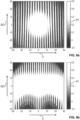
- Figures 9a and 9b each is a two-dimensional representation of a simulation as an example for the improved stability and robustness of the sequence S according to 8 shown.
- the simulations of Figures 9a and 9b relate to a system of five nuclear spin moments 10 and one electron spin moment 16, the interaction strengths W being Gaussian distributed.
- the simulations show the effect of pulse errors ⁇ and (frequency) detuning ⁇ on the polarization transfer PT.
- the pulse error ⁇ is plotted along the ordinate axis (y-axis) and the detuning ⁇ along the abscissa axis (x-axis), the gray scale representing the respective value of the polarization transfer PT.
- the pulse error ⁇ is defined here as the percentage deviation of a pulse amplitude ⁇ from an error-free pulse amplitude ⁇ 0 .
- the detuning ⁇ is understood here as a deviation of the frequency ⁇ of the high-frequency pulses from the Larmor frequency ⁇ e of the electron spin moment 16 in the magnetic field B, with the detuning ⁇ being plotted in units of megahertz (MHz).
- the polarization transfer PT is defined as ⁇ i ⁇ I e.g i t ⁇ ⁇ ⁇ I e.g i 0 ⁇ , that means as a sum of the differences between the expected values of the z-components of the spin operators of the nuclear spin moments 10 at the beginning and end of the sequence S.
- a j x and A j z describe the perpendicular and parallel components of the interaction (in MHz) between the electron spin moment 16 (spin operator S z ) and the j-th nuclear spin moment 10 (I).
- the electron spin moment 16 is manipulated by the sequence S in such a way that a polarization transfer from the electron spin moment 16 to an interacting nuclear spin moment 10 is made possible.
- the polarization transfer does not take place during a radio-frequency pulse P ki , P k'i , but in particular due to the sum of the individual spin dynamics during the time durations ⁇ ki , ⁇ k'i between the radio-frequency pulses P ki , P k'i .
- This enables polarization transfer independent of the Hartmann-Hahn condition. As a result, this is advantageously transferred to the flexibility; in particular, the technical requirements for the stability and quality of the high-frequency generator 26 are reduced as a result.
- the first nuclear spin moments 10 and electron spin moments 16 are part of a common molecular structure of a molecule or a common lattice structure of a solid as a material sample 4.
- the material sample 4 can also be a biological or medical sample such as a cell.
- the electron spin moment 16 is part of a free mono- or bi-radical molecule or a metallic ion or a photoexcitable triplet state molecule. It is essential that the electron spin moment 16 interacts with the nuclear spin moments 10 .
- the electron spin moment 16 is optically polarizable.
- one or more high-frequency pulses are acting on the nuclear spin moments 10, which have a frequency which is resonant with the Larmor frequency ⁇ Larmor of the nuclear spin moments 10 in the magnetic field B is.
Landscapes
- Physics & Mathematics (AREA)
- General Physics & Mathematics (AREA)
- Condensed Matter Physics & Semiconductors (AREA)
- High Energy & Nuclear Physics (AREA)
- Chemical & Material Sciences (AREA)
- Life Sciences & Earth Sciences (AREA)
- Health & Medical Sciences (AREA)
- Analytical Chemistry (AREA)
- Biochemistry (AREA)
- General Health & Medical Sciences (AREA)
- Immunology (AREA)
- Pathology (AREA)
- Hall/Mr Elements (AREA)
Claims (11)
- Procédé d'hyperpolarisation d'un échantillon de matériau (4) présentant plusieurs premiers moments de spin (10) d'un premier type de moment de spin- dans lequel le nombre de premiers moments de spin (10) est mis en interaction avec un deuxième moment de spin (16) d'un deuxième type de moment de spin,- dans lequel les premiers moments de spin (10) sont des moments de spin nucléaire, et le second moment de spin (16) est un moment de spin électronique,- dans lequel les premier et deuxième moments de spin (10, 16) sont soumis à un champ magnétique homogène (B),- dans lequel le deuxième moment de spin (16) est optiquement polarisé le long du champ magnétique (B),- dans lequel le deuxième moment de spin (16) est manipulé de manière cohérente au moyen d'une séquence (S) comprenant un certain nombre d'impulsions successives à haute fréquence (Pki, Pk'i) décalées dans le temps les unes par rapport aux autres par des pauses entre les impulsions à haute fréquence (Pki, Pk'i), la durée des pauses dépend de la fréquence de Larmor des premiers moments de spin dans le champ magnétique (B), de telle sorte que, comme effet d'une évolution du second moment de spin à la fin de la séquence, un processus de bascule et, par conséquent, un transfert de polarisation du second moment de spin (16) vers les premiers moments de spin (10) se produisent.
- Procédé selon la revendication 1, caractérisé en ce que
un seul angle de basculement de 90° et/ou 180° est utilisé pour chaque impulsion à haute fréquence de la séquence (S). - Procédé selon l'une des revendications 1 à 2, caractérisé en ce que les impulsions à haute fréquence sont générées le long de deux axes d'impulsion orientés perpendiculairement l'un par rapport à l'autre.
- Procédé selon l'une des revendications 1 à 3, caractérisé en ce qu'une impulsion à haute fréquence (Pki, Pk'i) de la séquence (S) est une impulsion composite dans laquelle une pluralité d'impulsions individuelles à haute fréquence est alignée le long de différents axes d'impulsion sans pause d'impulsion intermédiaire, de sorte qu'un angle de basculement effectif est réalisé lorsque l'impulsion composite est appliquée.
- Procédé selon l'une des revendications 1 à 4, caractérisé en ce qu'un moment de spin électronique d'un centre coloré (14) d'un échantillon solide (12) est utilisé comme second moment de spin (16).
- Procédé selon l'une des revendications 1 à 5, caractérisé en ce que pendant la seséquence (S), une section de séquence (S2) est générée dans laquelle quatre impulsions à haute fréquence, décalées l'une par rapport à l'autre au moyen de durées égales de pauses d'impulsion entre les impulsions à haute fréquence, chacune avec un angle de basculement de 90°, se succèdent.
- Procédé selon l'une des revendications 1 à 6, caractérisé en ce que, pendant la seséquence (S), une section de séquence (S2) est générée dans laquelle un certain nombre d'impulsions à haute fréquence décalées les unes par rapport aux autres au moyen de durées égales de pauses d'impulsion entre les impulsions à haute fréquence se succèdent avec un angle de basculement de 180° dans chaque cas, où les impulsions à haute fréquence sont alternativement formées comme des impulsions composites, dans lesquelles plusieurs impulsions individuelles à haute fréquence sont alignées le long de différents axes d'impulsion sans pause entre les impulsions, de sorte qu'un angle de basculement effectif est exécuté lorsque l'impulsion composite est appliquée.
- Procédé selon l'une des revendications 1 à 7, caractérisé en ce que pendant la séquence (S), une première section de séquence (S3) et une impulsion à haute fréquence avec un angle de basculement de 90° ainsi qu'une deuxième section de séquence (S4) sont générées successivement, pendant les sections de séquence (S3, S4), un certain nombre d'impulsions étant générées au moyen de durées égales (T) se succèdent avec un angle de basculement de 180° dans chaque cas, et les durées (T) de la deuxième section de séquence (S4) ayant un décalage temporel relatif (Δτ) par rapport aux durées (1) du premier segment de séquence (S3).
- Procédé selon l'une des revendications 1 à 8, caractérisé en ce que pendant la séquence (S), une première section de séquence (S5) et une deuxième section de séquence (S6) sont générées immédiatement l'une après l'autre, les sections de séquence (S5, S6) comprenant chacune deux impulsions à haute fréquence avec un angle de basculement de 90°, entre lesquelles, dans chaque cas, une impulsion à haute fréquence avec un angle de basculement de 180° est disposée de manière centrale, dans la première section de séquence (S5), les impulsions à haute fréquence avec un angle de basculement de 90° étant générées le long d'un premier axe d'impulsion et l'impulsion à haute fréquence avec un angle de basculement de 180° est générée le long d'un deuxième axe d'impulsion orienté perpendiculairement au premier axe d'impulsion, et dans la deuxième section de séquence (S6), les impulsions à haute fréquence avec un angle de basculement de 90° étant générées le long du deuxième axe d'impulsion et l'impulsion à haute fréquence avec un angle de basculement de 180° est générée le long du premier axe d'impulsion négatif.
- Procédé selon l'une quelconque des revendications 8 ou 9, caractérisé en ce que la ou les sections de la séquence (S1, S2, S3, S4, S5, S6) sont répétées plusieurs fois de suite au cours de la séquence (S).
- Dispositif (2) configuré pour hyperpolariser un échantillon de matériau (4) avant et/ou pendant une analyse par résonance magnétique selon le procédé de l'une quelconque des revendications 1 à 10.
Applications Claiming Priority (2)
| Application Number | Priority Date | Filing Date | Title |
|---|---|---|---|
| DE102016015567.1A DE102016015567A1 (de) | 2016-12-29 | 2016-12-29 | Verfahren und Vorrichtung zur Hyperpolarisierung einer Materialprobe |
| PCT/EP2017/084229 WO2018122124A1 (fr) | 2016-12-29 | 2017-12-21 | Procédé et dispositif pour l'hyperpolarisation d'une échantillon de matériau |
Publications (2)
| Publication Number | Publication Date |
|---|---|
| EP3563143A1 EP3563143A1 (fr) | 2019-11-06 |
| EP3563143B1 true EP3563143B1 (fr) | 2023-08-09 |
Family
ID=60935853
Family Applications (1)
| Application Number | Title | Priority Date | Filing Date |
|---|---|---|---|
| EP17825532.9A Active EP3563143B1 (fr) | 2016-12-29 | 2017-12-21 | Procédé et dispositif pour l'hyperpolarisation d'un échantillon de matériau |
Country Status (4)
| Country | Link |
|---|---|
| US (1) | US11119177B2 (fr) |
| EP (1) | EP3563143B1 (fr) |
| DE (1) | DE102016015567A1 (fr) |
| WO (1) | WO2018122124A1 (fr) |
Families Citing this family (4)
| Publication number | Priority date | Publication date | Assignee | Title |
|---|---|---|---|---|
| DE102017210309A1 (de) * | 2017-06-02 | 2018-12-06 | Universität Ulm | Verfahren und Vorrichtung zum Erzeugen eines Kernspinresonanz-Spektrums von Kernspinmomenten einer Probe |
| JP6789585B2 (ja) * | 2017-08-23 | 2020-11-25 | 国立大学法人大阪大学 | 原子核スピンの高偏極化方法及び高偏極化装置 |
| WO2020104854A2 (fr) * | 2018-11-21 | 2020-05-28 | Nvision Imaging Technologies Gmbh | Système et procédé de génération de matériaux hyperpolarisés |
| CN117949799B (zh) * | 2024-03-22 | 2024-06-11 | 吕梁学院 | 基于门电压测定有机自旋电子件性能的方法及测定系统 |
Family Cites Families (6)
| Publication number | Priority date | Publication date | Assignee | Title |
|---|---|---|---|---|
| GB0001727D0 (en) * | 2000-01-25 | 2000-03-15 | Oxford Instr Uk Ltd | Hyperpolarization of a noble gas |
| GB0308586D0 (en) * | 2003-04-14 | 2003-05-21 | Amersham Health R & D Ab | Method and arrangements in NMR spectroscopy |
| US7508212B2 (en) * | 2007-03-22 | 2009-03-24 | Wisconsin Alumni Research Foundation | RF coil assembly and method for practicing magnetization transfer on magnetic resonance imaging and spectroscopy systems |
| EP2790031B1 (fr) * | 2013-04-08 | 2018-01-31 | Universität Ulm | Procédé d'hyperpolarisation de spin nucléaire dans un diamant |
| US9642924B2 (en) * | 2013-08-29 | 2017-05-09 | Duke University | Contrast agents based on long-lived nuclear singlet states and related methods |
| US10338052B2 (en) * | 2015-11-30 | 2019-07-02 | Vanderbilt University | Methods of detecting sulfur-containing compounds |
-
2016
- 2016-12-29 DE DE102016015567.1A patent/DE102016015567A1/de not_active Ceased
-
2017
- 2017-12-21 US US16/474,147 patent/US11119177B2/en active Active
- 2017-12-21 WO PCT/EP2017/084229 patent/WO2018122124A1/fr not_active Ceased
- 2017-12-21 EP EP17825532.9A patent/EP3563143B1/fr active Active
Non-Patent Citations (1)
| Title |
|---|
| K. TATEISHI ET AL: "Room temperature hyperpolarization of nuclear spins in bulk", PROCEEDINGS OF THE NATIONAL ACADEMY OF SCIENCES, vol. 111, no. 21, 12 May 2014 (2014-05-12), US, pages 7527 - 7530, XP055579389, ISSN: 0027-8424, DOI: 10.1073/pnas.1315778111 * |
Also Published As
| Publication number | Publication date |
|---|---|
| US11119177B2 (en) | 2021-09-14 |
| DE102016015567A1 (de) | 2018-07-05 |
| EP3563143A1 (fr) | 2019-11-06 |
| WO2018122124A1 (fr) | 2018-07-05 |
| US20190346527A1 (en) | 2019-11-14 |
Similar Documents
| Publication | Publication Date | Title |
|---|---|---|
| EP3563143B1 (fr) | Procédé et dispositif pour l'hyperpolarisation d'un échantillon de matériau | |
| EP2552310B1 (fr) | Procédé d'imagerie par de petites particules magnétiques et dispositif utilisé à cet effet | |
| EP0184225A2 (fr) | Procédé pour la tomographie à résonance nucléaire magnétique | |
| DE2847641C2 (fr) | ||
| EP3380857B1 (fr) | Dispositif et procédé pour générer et détecter une aimantation transitoire d'un échantillon | |
| DE102017210309A1 (de) | Verfahren und Vorrichtung zum Erzeugen eines Kernspinresonanz-Spektrums von Kernspinmomenten einer Probe | |
| DE10138961B4 (de) | Verfahren zur Messung der Magnetresonanz (NMR) mittels Steady State Signalen (SSFP) | |
| DE3422688A1 (de) | Verfahren zur analyse der eigenschaften eines gegenstandes oder eines magnetischen feldes | |
| DE102016212018A1 (de) | HF-Spulenanordnung | |
| DE10112625B4 (de) | Verfahren zur Bildung frequenz- und/oder amplitudenmodulierter elektromagnetischer Pulse zur Induzierung adiabatischer Transfervorgänge in quantenmechanischen Systemen | |
| DE2061018A1 (de) | Verfahren zur Aufnahme von Spinresonanzspektren und hierfuer geeignetes Spinresonanz-Spektrometer | |
| DE102018203845A1 (de) | Verfahren und Vorrichtung zum Messen einer Magnetfeldrichtung | |
| EP3380856B1 (fr) | Dispositif pour générer et détecter une résonance magnétique d'un échantillon | |
| DE102015016021A1 (de) | Verfahren und Anordnung zur Bestimmung von statischen elektrischen und/oder statischen magnetischen Feldern und der Topologie von Bauteilen mittels einer auf Quanteneffekten beruhenden Sensortechnologie | |
| DE10112704B4 (de) | Verfahren zur Messung der Magnetresonanz (NMR) mittels Driven Equilibrium | |
| DE69826742T2 (de) | Gerät und Verfahren zur Erzeugung von Gradientenmagnetfeldern für hochauflösende NMR-Experimente im magischen Winkel | |
| EP0164142B1 (fr) | Procédé et dispositif pour déterminer la distribution de la magnétisation nucléaire dans une région d'un corps | |
| DE102016102025A1 (de) | Vorrichtung zur Erzeugung und Detektion einer magnetischen Resonanz einer Probe | |
| DE102005040540B4 (de) | Verfahren und Gerät zur Nachweisverbesserung einer schwachsensitiven Atomkernart in der NMR-Spektroskopie | |
| DE102005015069B4 (de) | Verfahren zur Vermeidung linearer Phasenfehler in der Magnetresonanz-Spektroskopie | |
| EP1107015B1 (fr) | Procédé de la résonance magnétique pour la génération d'impulsions navigatrices | |
| EP0233675B1 (fr) | Procédé pour déterminer la distribution spectrale de la magnétisation nucléaire dans un volume limité et dispositif pour la mise en oeuvre du procédé | |
| EP2577341B1 (fr) | Relaxométrie par rmn à cyclage de champ | |
| DE10233999B4 (de) | Verfahren der Festkörper-NMR mit inverser Detektion | |
| EP0515718B1 (fr) | Mesure de taux de relaxation croisée entre des paires de noyaux sélectionnés |
Legal Events
| Date | Code | Title | Description |
|---|---|---|---|
| STAA | Information on the status of an ep patent application or granted ep patent |
Free format text: STATUS: UNKNOWN |
|
| STAA | Information on the status of an ep patent application or granted ep patent |
Free format text: STATUS: THE INTERNATIONAL PUBLICATION HAS BEEN MADE |
|
| PUAI | Public reference made under article 153(3) epc to a published international application that has entered the european phase |
Free format text: ORIGINAL CODE: 0009012 |
|
| STAA | Information on the status of an ep patent application or granted ep patent |
Free format text: STATUS: REQUEST FOR EXAMINATION WAS MADE |
|
| 17P | Request for examination filed |
Effective date: 20190626 |
|
| AK | Designated contracting states |
Kind code of ref document: A1 Designated state(s): AL AT BE BG CH CY CZ DE DK EE ES FI FR GB GR HR HU IE IS IT LI LT LU LV MC MK MT NL NO PL PT RO RS SE SI SK SM TR |
|
| AX | Request for extension of the european patent |
Extension state: BA ME |
|
| RIN1 | Information on inventor provided before grant (corrected) |
Inventor name: WANG, ZHENYU Inventor name: CHEN, QIONG Inventor name: SCHWARTZ, ILAI Inventor name: PLENIO, MARTIN |
|
| DAV | Request for validation of the european patent (deleted) | ||
| DAX | Request for extension of the european patent (deleted) | ||
| STAA | Information on the status of an ep patent application or granted ep patent |
Free format text: STATUS: EXAMINATION IS IN PROGRESS |
|
| 17Q | First examination report despatched |
Effective date: 20210825 |
|
| GRAP | Despatch of communication of intention to grant a patent |
Free format text: ORIGINAL CODE: EPIDOSNIGR1 |
|
| STAA | Information on the status of an ep patent application or granted ep patent |
Free format text: STATUS: GRANT OF PATENT IS INTENDED |
|
| INTG | Intention to grant announced |
Effective date: 20221207 |
|
| GRAJ | Information related to disapproval of communication of intention to grant by the applicant or resumption of examination proceedings by the epo deleted |
Free format text: ORIGINAL CODE: EPIDOSDIGR1 |
|
| STAA | Information on the status of an ep patent application or granted ep patent |
Free format text: STATUS: EXAMINATION IS IN PROGRESS |
|
| GRAP | Despatch of communication of intention to grant a patent |
Free format text: ORIGINAL CODE: EPIDOSNIGR1 |
|
| STAA | Information on the status of an ep patent application or granted ep patent |
Free format text: STATUS: GRANT OF PATENT IS INTENDED |
|
| INTC | Intention to grant announced (deleted) | ||
| INTG | Intention to grant announced |
Effective date: 20230227 |
|
| GRAS | Grant fee paid |
Free format text: ORIGINAL CODE: EPIDOSNIGR3 |
|
| P01 | Opt-out of the competence of the unified patent court (upc) registered |
Effective date: 20230526 |
|
| GRAA | (expected) grant |
Free format text: ORIGINAL CODE: 0009210 |
|
| STAA | Information on the status of an ep patent application or granted ep patent |
Free format text: STATUS: THE PATENT HAS BEEN GRANTED |
|
| AK | Designated contracting states |
Kind code of ref document: B1 Designated state(s): AL AT BE BG CH CY CZ DE DK EE ES FI FR GB GR HR HU IE IS IT LI LT LU LV MC MK MT NL NO PL PT RO RS SE SI SK SM TR |
|
| REG | Reference to a national code |
Ref country code: GB Ref legal event code: FG4D Free format text: NOT ENGLISH |
|
| REG | Reference to a national code |
Ref country code: CH Ref legal event code: EP |
|
| RAP4 | Party data changed (patent owner data changed or rights of a patent transferred) |
Owner name: NVISION IMAGING TECHNOLOGIES GMBH |
|
| REG | Reference to a national code |
Ref country code: IE Ref legal event code: FG4D Free format text: LANGUAGE OF EP DOCUMENT: GERMAN |
|
| REG | Reference to a national code |
Ref country code: DE Ref legal event code: R096 Ref document number: 502017015210 Country of ref document: DE |
|
| REG | Reference to a national code |
Ref country code: LT Ref legal event code: MG9D |
|
| REG | Reference to a national code |
Ref country code: NL Ref legal event code: MP Effective date: 20230809 |
|
| PG25 | Lapsed in a contracting state [announced via postgrant information from national office to epo] |
Ref country code: GR Free format text: LAPSE BECAUSE OF FAILURE TO SUBMIT A TRANSLATION OF THE DESCRIPTION OR TO PAY THE FEE WITHIN THE PRESCRIBED TIME-LIMIT Effective date: 20231110 |
|
| PG25 | Lapsed in a contracting state [announced via postgrant information from national office to epo] |
Ref country code: IS Free format text: LAPSE BECAUSE OF FAILURE TO SUBMIT A TRANSLATION OF THE DESCRIPTION OR TO PAY THE FEE WITHIN THE PRESCRIBED TIME-LIMIT Effective date: 20231209 |
|
| PG25 | Lapsed in a contracting state [announced via postgrant information from national office to epo] |
Ref country code: SE Free format text: LAPSE BECAUSE OF FAILURE TO SUBMIT A TRANSLATION OF THE DESCRIPTION OR TO PAY THE FEE WITHIN THE PRESCRIBED TIME-LIMIT Effective date: 20230809 Ref country code: RS Free format text: LAPSE BECAUSE OF FAILURE TO SUBMIT A TRANSLATION OF THE DESCRIPTION OR TO PAY THE FEE WITHIN THE PRESCRIBED TIME-LIMIT Effective date: 20230809 Ref country code: PT Free format text: LAPSE BECAUSE OF FAILURE TO SUBMIT A TRANSLATION OF THE DESCRIPTION OR TO PAY THE FEE WITHIN THE PRESCRIBED TIME-LIMIT Effective date: 20231211 Ref country code: NO Free format text: LAPSE BECAUSE OF FAILURE TO SUBMIT A TRANSLATION OF THE DESCRIPTION OR TO PAY THE FEE WITHIN THE PRESCRIBED TIME-LIMIT Effective date: 20231109 Ref country code: NL Free format text: LAPSE BECAUSE OF FAILURE TO SUBMIT A TRANSLATION OF THE DESCRIPTION OR TO PAY THE FEE WITHIN THE PRESCRIBED TIME-LIMIT Effective date: 20230809 Ref country code: LV Free format text: LAPSE BECAUSE OF FAILURE TO SUBMIT A TRANSLATION OF THE DESCRIPTION OR TO PAY THE FEE WITHIN THE PRESCRIBED TIME-LIMIT Effective date: 20230809 Ref country code: LT Free format text: LAPSE BECAUSE OF FAILURE TO SUBMIT A TRANSLATION OF THE DESCRIPTION OR TO PAY THE FEE WITHIN THE PRESCRIBED TIME-LIMIT Effective date: 20230809 Ref country code: IS Free format text: LAPSE BECAUSE OF FAILURE TO SUBMIT A TRANSLATION OF THE DESCRIPTION OR TO PAY THE FEE WITHIN THE PRESCRIBED TIME-LIMIT Effective date: 20231209 Ref country code: HR Free format text: LAPSE BECAUSE OF FAILURE TO SUBMIT A TRANSLATION OF THE DESCRIPTION OR TO PAY THE FEE WITHIN THE PRESCRIBED TIME-LIMIT Effective date: 20230809 Ref country code: GR Free format text: LAPSE BECAUSE OF FAILURE TO SUBMIT A TRANSLATION OF THE DESCRIPTION OR TO PAY THE FEE WITHIN THE PRESCRIBED TIME-LIMIT Effective date: 20231110 Ref country code: FI Free format text: LAPSE BECAUSE OF FAILURE TO SUBMIT A TRANSLATION OF THE DESCRIPTION OR TO PAY THE FEE WITHIN THE PRESCRIBED TIME-LIMIT Effective date: 20230809 |
|
| PG25 | Lapsed in a contracting state [announced via postgrant information from national office to epo] |
Ref country code: PL Free format text: LAPSE BECAUSE OF FAILURE TO SUBMIT A TRANSLATION OF THE DESCRIPTION OR TO PAY THE FEE WITHIN THE PRESCRIBED TIME-LIMIT Effective date: 20230809 |
|
| PG25 | Lapsed in a contracting state [announced via postgrant information from national office to epo] |
Ref country code: ES Free format text: LAPSE BECAUSE OF FAILURE TO SUBMIT A TRANSLATION OF THE DESCRIPTION OR TO PAY THE FEE WITHIN THE PRESCRIBED TIME-LIMIT Effective date: 20230809 |
|
| PG25 | Lapsed in a contracting state [announced via postgrant information from national office to epo] |
Ref country code: SM Free format text: LAPSE BECAUSE OF FAILURE TO SUBMIT A TRANSLATION OF THE DESCRIPTION OR TO PAY THE FEE WITHIN THE PRESCRIBED TIME-LIMIT Effective date: 20230809 Ref country code: RO Free format text: LAPSE BECAUSE OF FAILURE TO SUBMIT A TRANSLATION OF THE DESCRIPTION OR TO PAY THE FEE WITHIN THE PRESCRIBED TIME-LIMIT Effective date: 20230809 Ref country code: ES Free format text: LAPSE BECAUSE OF FAILURE TO SUBMIT A TRANSLATION OF THE DESCRIPTION OR TO PAY THE FEE WITHIN THE PRESCRIBED TIME-LIMIT Effective date: 20230809 Ref country code: EE Free format text: LAPSE BECAUSE OF FAILURE TO SUBMIT A TRANSLATION OF THE DESCRIPTION OR TO PAY THE FEE WITHIN THE PRESCRIBED TIME-LIMIT Effective date: 20230809 Ref country code: DK Free format text: LAPSE BECAUSE OF FAILURE TO SUBMIT A TRANSLATION OF THE DESCRIPTION OR TO PAY THE FEE WITHIN THE PRESCRIBED TIME-LIMIT Effective date: 20230809 Ref country code: CZ Free format text: LAPSE BECAUSE OF FAILURE TO SUBMIT A TRANSLATION OF THE DESCRIPTION OR TO PAY THE FEE WITHIN THE PRESCRIBED TIME-LIMIT Effective date: 20230809 Ref country code: SK Free format text: LAPSE BECAUSE OF FAILURE TO SUBMIT A TRANSLATION OF THE DESCRIPTION OR TO PAY THE FEE WITHIN THE PRESCRIBED TIME-LIMIT Effective date: 20230809 |
|
| REG | Reference to a national code |
Ref country code: DE Ref legal event code: R097 Ref document number: 502017015210 Country of ref document: DE |
|
| PG25 | Lapsed in a contracting state [announced via postgrant information from national office to epo] |
Ref country code: IT Free format text: LAPSE BECAUSE OF FAILURE TO SUBMIT A TRANSLATION OF THE DESCRIPTION OR TO PAY THE FEE WITHIN THE PRESCRIBED TIME-LIMIT Effective date: 20230809 |
|
| PLBE | No opposition filed within time limit |
Free format text: ORIGINAL CODE: 0009261 |
|
| STAA | Information on the status of an ep patent application or granted ep patent |
Free format text: STATUS: NO OPPOSITION FILED WITHIN TIME LIMIT |
|
| 26N | No opposition filed |
Effective date: 20240513 |
|
| PG25 | Lapsed in a contracting state [announced via postgrant information from national office to epo] |
Ref country code: SI Free format text: LAPSE BECAUSE OF FAILURE TO SUBMIT A TRANSLATION OF THE DESCRIPTION OR TO PAY THE FEE WITHIN THE PRESCRIBED TIME-LIMIT Effective date: 20230809 |
|
| REG | Reference to a national code |
Ref country code: CH Ref legal event code: PL |
|
| PG25 | Lapsed in a contracting state [announced via postgrant information from national office to epo] |
Ref country code: LU Free format text: LAPSE BECAUSE OF NON-PAYMENT OF DUE FEES Effective date: 20231221 |
|
| PG25 | Lapsed in a contracting state [announced via postgrant information from national office to epo] |
Ref country code: MC Free format text: LAPSE BECAUSE OF FAILURE TO SUBMIT A TRANSLATION OF THE DESCRIPTION OR TO PAY THE FEE WITHIN THE PRESCRIBED TIME-LIMIT Effective date: 20230809 |
|
| REG | Reference to a national code |
Ref country code: BE Ref legal event code: MM Effective date: 20231231 |
|
| PG25 | Lapsed in a contracting state [announced via postgrant information from national office to epo] |
Ref country code: MC Free format text: LAPSE BECAUSE OF FAILURE TO SUBMIT A TRANSLATION OF THE DESCRIPTION OR TO PAY THE FEE WITHIN THE PRESCRIBED TIME-LIMIT Effective date: 20230809 Ref country code: LU Free format text: LAPSE BECAUSE OF NON-PAYMENT OF DUE FEES Effective date: 20231221 |
|
| REG | Reference to a national code |
Ref country code: IE Ref legal event code: MM4A |
|
| PG25 | Lapsed in a contracting state [announced via postgrant information from national office to epo] |
Ref country code: IE Free format text: LAPSE BECAUSE OF NON-PAYMENT OF DUE FEES Effective date: 20231221 |
|
| PG25 | Lapsed in a contracting state [announced via postgrant information from national office to epo] |
Ref country code: BE Free format text: LAPSE BECAUSE OF NON-PAYMENT OF DUE FEES Effective date: 20231231 |
|
| PG25 | Lapsed in a contracting state [announced via postgrant information from national office to epo] |
Ref country code: CH Free format text: LAPSE BECAUSE OF NON-PAYMENT OF DUE FEES Effective date: 20231231 |
|
| PG25 | Lapsed in a contracting state [announced via postgrant information from national office to epo] |
Ref country code: IE Free format text: LAPSE BECAUSE OF NON-PAYMENT OF DUE FEES Effective date: 20231221 Ref country code: CH Free format text: LAPSE BECAUSE OF NON-PAYMENT OF DUE FEES Effective date: 20231231 Ref country code: BE Free format text: LAPSE BECAUSE OF NON-PAYMENT OF DUE FEES Effective date: 20231231 |
|
| PG25 | Lapsed in a contracting state [announced via postgrant information from national office to epo] |
Ref country code: BG Free format text: LAPSE BECAUSE OF FAILURE TO SUBMIT A TRANSLATION OF THE DESCRIPTION OR TO PAY THE FEE WITHIN THE PRESCRIBED TIME-LIMIT Effective date: 20230809 |
|
| PG25 | Lapsed in a contracting state [announced via postgrant information from national office to epo] |
Ref country code: BG Free format text: LAPSE BECAUSE OF FAILURE TO SUBMIT A TRANSLATION OF THE DESCRIPTION OR TO PAY THE FEE WITHIN THE PRESCRIBED TIME-LIMIT Effective date: 20230809 |
|
| REG | Reference to a national code |
Ref country code: AT Ref legal event code: MM01 Ref document number: 1598095 Country of ref document: AT Kind code of ref document: T Effective date: 20231221 |
|
| PG25 | Lapsed in a contracting state [announced via postgrant information from national office to epo] |
Ref country code: AT Free format text: LAPSE BECAUSE OF NON-PAYMENT OF DUE FEES Effective date: 20231221 |
|
| PG25 | Lapsed in a contracting state [announced via postgrant information from national office to epo] |
Ref country code: CY Free format text: LAPSE BECAUSE OF FAILURE TO SUBMIT A TRANSLATION OF THE DESCRIPTION OR TO PAY THE FEE WITHIN THE PRESCRIBED TIME-LIMIT; INVALID AB INITIO Effective date: 20171221 |
|
| PG25 | Lapsed in a contracting state [announced via postgrant information from national office to epo] |
Ref country code: HU Free format text: LAPSE BECAUSE OF FAILURE TO SUBMIT A TRANSLATION OF THE DESCRIPTION OR TO PAY THE FEE WITHIN THE PRESCRIBED TIME-LIMIT; INVALID AB INITIO Effective date: 20171221 |
|
| PG25 | Lapsed in a contracting state [announced via postgrant information from national office to epo] |
Ref country code: TR Free format text: LAPSE BECAUSE OF FAILURE TO SUBMIT A TRANSLATION OF THE DESCRIPTION OR TO PAY THE FEE WITHIN THE PRESCRIBED TIME-LIMIT Effective date: 20230809 |
|
| PGFP | Annual fee paid to national office [announced via postgrant information from national office to epo] |
Ref country code: GB Payment date: 20251218 Year of fee payment: 9 |
|
| PGFP | Annual fee paid to national office [announced via postgrant information from national office to epo] |
Ref country code: FR Payment date: 20251217 Year of fee payment: 9 |
|
| PGFP | Annual fee paid to national office [announced via postgrant information from national office to epo] |
Ref country code: DE Payment date: 20251222 Year of fee payment: 9 |