EP3563201B1 - Netzwerk für beleuchtungsautomation - Google Patents
Netzwerk für beleuchtungsautomation Download PDFInfo
- Publication number
- EP3563201B1 EP3563201B1 EP17886901.2A EP17886901A EP3563201B1 EP 3563201 B1 EP3563201 B1 EP 3563201B1 EP 17886901 A EP17886901 A EP 17886901A EP 3563201 B1 EP3563201 B1 EP 3563201B1
- Authority
- EP
- European Patent Office
- Prior art keywords
- data
- sub
- protocol
- sensor
- lighting
- Prior art date
- Legal status (The legal status is an assumption and is not a legal conclusion. Google has not performed a legal analysis and makes no representation as to the accuracy of the status listed.)
- Active
Links
Images

Classifications
-
- H—ELECTRICITY
- H04—ELECTRIC COMMUNICATION TECHNIQUE
- H04L—TRANSMISSION OF DIGITAL INFORMATION, e.g. TELEGRAPHIC COMMUNICATION
- H04L67/00—Network arrangements or protocols for supporting network services or applications
- H04L67/01—Protocols
- H04L67/12—Protocols specially adapted for proprietary or special-purpose networking environments, e.g. medical networks, sensor networks, networks in vehicles or remote metering networks
-
- H—ELECTRICITY
- H04—ELECTRIC COMMUNICATION TECHNIQUE
- H04L—TRANSMISSION OF DIGITAL INFORMATION, e.g. TELEGRAPHIC COMMUNICATION
- H04L12/00—Data switching networks
- H04L12/66—Arrangements for connecting between networks having differing types of switching systems, e.g. gateways
-
- H—ELECTRICITY
- H05—ELECTRIC TECHNIQUES NOT OTHERWISE PROVIDED FOR
- H05B—ELECTRIC HEATING; ELECTRIC LIGHT SOURCES NOT OTHERWISE PROVIDED FOR; CIRCUIT ARRANGEMENTS FOR ELECTRIC LIGHT SOURCES, IN GENERAL
- H05B47/00—Circuit arrangements for operating light sources in general, i.e. where the type of light source is not relevant
- H05B47/10—Controlling the light source
- H05B47/175—Controlling the light source by remote control
Definitions
- Third party automation networks are used to control various devices, sensors, and the like.
- the third party automation networks each use a proprietary protocol to allow a device or sensor to communicate with a control server of the third party automation network.
- lighting networks are not adapted to work with these third party automation networks.
- US2015/102733A1 proposes an intelligent illumination device.
- US9456293B2 proposes a method for communicating data within a lighting sensory network.
- WO2006/017796A2 proposes an environment monitoring system
- US2016/352577A1 relates to controlling remote devices using a clouds infrastructure.
- the present invention discloses a lighting network that can communicate with a third party automation network.
- third party automation networks are used to control various devices, sensors, and the like.
- the third party automation networks each use a proprietary protocol to allow a device or sensor to communicate with a control server of the third party automation network.
- lighting networks are not adapted to work with these third party automation networks.
- Lighting devices have evolved such that lights now have communication capability.
- lighting devices may be capable of communicating with one another and transmitting control signals or lighting data to a lighting system control server.
- the control signals and data packets can be transmitted between the lighting devices and to/from the lighting system control server via either a wired or wireless connection.
- One embodiment of the present disclosure provides a modified lighting system control server that provides an interface and a protocol conversion between the lighting network and the third party automation network.
- different types of data including data unrelated to the lighting devices or the lighting network, may be transmitted over the lighting network to the third party automation network for further analysis and correlation.
- sensor data that is triggered throughout a building, or a factory may be wirelessly sent over the lighting network to a third party automation control server.
- the third party automation control server may then correlate the sensor data to potential security breaches within the building or factory.
- workers in a mine may wear heart beat monitors and breathing monitors. The data for each worker may be transmitted via the lighting network to a third party automation control server for further analysis and correlation.
- the heart beat and breathing data may be used to identify those workers that may be experiencing a health issue or require a break. Numerous other examples may be evident within the context of the present disclosure.
- the present disclosure may also provide a plurality of sub-routines that are used by the third party automation control server to properly analyze or correlate the translated data for a particular application.
- some third party automation service providers may use add on instructions (AOIs) to modify software of a third party controller for a particular application.
- Applications or sub-routines may be written to correlate sensor data to security breaches or to correlate heart beat data and breathing data to potential health issues.
- These sub-routines may be software code, instructions, programs, and the like that are stored in memory and executed by a processor (e.g., a third party automation controller/server).
- the sub-routines may be stored within a database or memory of the lighting network control server and be downloaded by the third party automation network.
- a library of sub-routines may be stored at the lighting network control server.
- a graphical user interface may be used to view, select and download the sub-routines that a third party automation network desires for one or more different applications.
- the embodiments of the present disclosure provide modifications to a lighting network to allow existing third party automation networks to leverage the data transmission capabilities of the lighting network. As a result, costs savings and efficiency may be realized as additional hardware costs and installation costs for deploying a data transmission network may be avoided.
- FIG. 1 illustrates an example network 100 of the present disclosure.
- the network 100 may include a lighting network control server 102 that is in communication with a lighting network 104 and a third party automation controller 118.
- a lighting network control server 102 may include a Dialight ® Architecture for Control System (DACS) Enterprise Server.
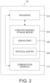
- FIG. 2 illustrates a block diagram of an example lighting network control server 102.
- DAS Dialight ® Architecture for Control System
- the lighting network control server 102 may include a processor 202, a computer readable storage medium 204, and a communication interface 210.
- the processor 202 may be communicatively coupled to the computer readable storage medium 204 and the communication interface 210.
- the computer readable storage medium 204 may be a non-transitory computer readable storage medium such as a hard disk drive, random access memory (RAM), read only memory (ROM), and the like.
- the computer readable storage medium 204 may store sub-routines 206 and protocol adapter 208.
- the sub-routines 206 may include instructions that when executed by a processor analyze non-light related data for the third party automation controller 118, as discussed in further details below.
- the sub-routines 206 may be stored on a database that is external to the lighting network control server 102.
- the lighting network control server 102 may access the database of the sub-routines 206 via the communication interface 210.
- the protocol adapter 208 may include instructions that when executed by a processor translate non-light related data in a first format into a second format that is compatible with the third party automation controller 118, as discussed in further details below. For example, the protocol adapter 208 may generate a second set of translated data that is in a protocol format that can be understood or read by the third party automation controller 118.
- the communication interface 210 may be any type of communication interface.
- the communication interface 210 may be a wired or wireless communication interface 210.
- the communication interface 210 may include a plurality of different communication interfaces 210.
- the communication interface 210 may include a wired interface to communicate with the lighting network 104 and a wireless interface to communicate with the third party automation controller 119.
- the lighting network control server 102 may be used to control lighting devices 112 in the lighting network 104.
- the lighting devices 112 may be beacon lights, high bay lights, or any other type of indoor or outdoor lighting device or fixture.
- the lighting devices 112 may be light emitting diode (LED) based lights.
- LED light emitting diode
- the lighting devices 112 may be modified with a communication module 114.
- the communication module 114 may be any type of communication module 114 that can be used for wired or wireless communications or connections to other lighting devices 112 and a gateway (GW) 110 that is also in the lighting network 104.
- the lighting devices 112 may collect light data (e.g., hours of operation, energy use, and the like) and transmit the data via the communication module 114 to the gateway 110 via a local area network (LAN) (e.g., via a Wi-Fi network).
- the gateway 110 may connect to a wide area network (WAN) (e.g., via broadband network, Ethernet network, and the like) and may transmit the data to the lighting network control server 102.
- the lighting network control server 102 may also transmit control signals to the lighting devices 112 via the same series of connections and the gateway 110.
- the network 100 may also include a user interface (UI) 122 to setup and commission the lighting devices 112.
- UI user interface
- the III 122 may be deployed via any type of endpoint device, such as for example, a laptop computer, a desktop computer, a smartphone, a tablet computer, and the like.
- the communications capability of the lighting devices 112, the gateway 110 and the lighting network control server 102 may be used to collect non-light related data and transmit that data to a third party automation network.
- data from an external device 116 may be collected and sent to the third party automation network for further analysis or correlations.
- non-light related data may be any type of data that is not associated with operation of any of the lighting devices 112 in the lighting network 104. In one embodiment, “non-light related data” may be any type of data that is collected from the external device 116 that is a not a light device.
- An example of the external device 116 may be a heartbeat monitor attached to employees working in an underground tunnel.
- the non-light related data may include the heartbeat data.
- the non-light related data and light related may be transmitted across the lighting network 104 back to the lighting network control server 102.
- the external device 116 may include sensor devices and the non-light related data may include movement data that may be transmitted across the lighting network 104 back to the lighting network control server 102.
- the non-light related data may include building information such as temperature, door lock status, video data, and the like.
- the non-light related data may be transmitted across the lighting network 104 back to the lighting network control server 102. It should be noted that the above are only a few examples of non-light related data and other examples may be within the scope of the present disclosure.
- the third party automation network may include a third party automation controller 118 and a user interface (UI) 120.
- An example of the third party automation controller 118 may be a programmable logic controller (PLC) used by Rockwell ® automation systems.
- PLC programmable logic controller
- the third party automation controller 118 may use a particular communication protocol that is not compatible with other automation networks or the protocol used by the lighting network control server 102 or the lighting network 104 that includes the lighting devices 112 and the gateway 110.
- the lighting network control server 102 may include the communication interface 210 to establish the wired or wireless connection to the third party automation controller 118.
- communication interface 210 may be a physical interface that provides either ports for a physical/wired connection or logical ports for a wireless connection to the third party automation controller 118.
- the protocol adapter 208 may translate the data in collected in the communication protocol used by the lighting network 104 (e.g., device control protocol (DCP) over Ethernet) into a communication protocol used by the third party automation controller 118.
- DCP device control protocol
- third party automation networks such as Rockwell may use protocols such as Ethernet/IP ® , BACnet/IPO, ControlNet ® , Modbus ® , ProfiNet ® , and the like.
- the protocol adapter 208 may translate the communication protocol used to transport the data (e.g., light related and/or non-light related) via the lighting network 104 into an appropriate communication protocol used by the third party automation controller 118.
- additional code can be used to analyze the data and produce a desired output for a particular application.
- the third party automation controller 118 may provide the hardware and necessary processing capability, but the additional code is used to leverage the hardware and processing capability to analyze the data.
- the sub-routines 206 may comprise a library or a plurality of add-on instructions that can be browsed and downloaded to the third party automation controller 118 and the lighting network control server 102. In one embodiment, the same sub-routine or different sub-routines may be downloaded and installed on the lighting network control server 102 and the third party automation controller 118. In one embodiment, the sub-routine may modify the controller software executed by the third party automation controller 118 for a particular application to analyze data received from the network 100. In other words, the sub-routine on the lighting network control server 102 and the third party automation controller 118 may work together to analyze the data that is collected for a particular application.
- the UI 120 may provide a graphical user interface (GUI) that can display the available sub-routines 206 that can be downloaded to the third party automation controller 118.
- GUI graphical user interface
- a user is not required to manually create or implement code to analyze the data.
- the sub-routines 206 may be written in advance by the lighting network service provider and stored in memory (e.g., the sub-routines 206).
- the external device 116 may be a plurality of sensors that are located throughout a building or factory that uses the lighting devices 112 or has the lighting network 104.
- the building or factory is remotely located (e.g., in a different geographic location or region) from the lighting network control server 102.
- the sensor data e.g., the non-light related data
- the communication module 114 of the lighting devices 112 may be collected by the communication module 114 of the lighting devices 112 and transmitted to the GW 110.
- the data may be collected continuously or periodically (e.g., every hour, every day, and the like).
- the sensor data may be transmitted to the lighting network control server 102.
- a user of the third party automation network may want to use the sensor data to determine locations within the building or factory that have a potential security threat.
- a user may use the UI 120 to download a sub-routine, from the sub-routines 206, related to correlating sensor data into potential security threats.
- the sub-routine may be downloaded from the sub-routines 206 and installed on the third party automation controller 118.
- the third party automation controller 118 may request the sensor data from the lighting network control server 102.
- the protocol adapter 208 may translate the sensor data from a DCP over Ethernet protocol into an EtherNet IP protocol that the third party automation controller 118 may understand (e.g., the third party automation controller 118 may be a Rockwell automation control server). In one embodiment, translating may include the protocol adapter 208 generating a new set of data that is in the EtherNet IP protocol that can be understood by the third party automation controller 118.
- the third party automation controller 118 may then use the sub-routine downloaded from the sub-routines 206 to analyze the translated sensor data and provide an output that indicates which locations in the building or factory are compromised based on the sensor data.
- the external device 116 may be health monitors worn by workers in a mining tunnel that use a plurality of lighting devices 112 with the communication module 114.
- the health monitors worn by the workers may transmit heart rate and breathing rate data via the lighting devices 112 and the GW 110 to the lighting network control server 102.
- the location of the lighting device 112 that most recently collected the health monitor data may also provide a location tracking of a worker in the mining tunnel.
- a user of the third party automation network may want to use the health monitor data to determine whether a worker is experiencing a health condition or is exposed to some harmful particulates that the worker may not be aware of.
- the user may use the UI 120 to download a sub-routine related to correlating heart rate and breathing rate to a potential health risk or condition.
- the sub-routine may be downloaded from the sub-routines 206 and installed on the third party automation controller 118.
- the third party automation controller 118 may request the heart rate and breathing rate data from the lighting network control server 102.
- the protocol adapter 208 may translate the heart rate and breathing rate data from a DCP over Ethernet protocol into an EtherNet IP protocol that the third party automation controller 118 may understand (e.g., the third party automation controller 118 may be a Rockwell automation control server).
- the third party automation controller 118 may use the sub-routine downloaded from the sub-routines 206 to analyze the heart rate and breathing rate data and provide an output that indicates which workers may be experiencing a health condition or be at a health risk based on the data.
- FIG. 3 illustrates a flowchart of an example method 300 for translating non-light related data packets into a protocol that is compatible with a third party automation server.
- one or more steps or operations of the method 300 may be performed by the lighting network control server 102 or a computer as illustrated in FIG. 4 and discussed below.
- the method 300 begins.
- the method 300 receives a non-light related data packet from a lighting network.
- the non-light related data packet may be generated by an external device such as a building sensor, a heartbeat monitor, a breathing monitor, a video imager, a thermostat, and the like.
- the external device may be in communication with lighting devices that have a communication module in the lighting network.
- the non-light related data may be transmitted to the lighting devices with the communication module.
- the non-light related data may be transmitted across the lighting network with or without light related data (e.g., data related to operation of the lighting devices) to a gateway and then to a light network control server.
- the non-light related data may be received in response to a request for the data from a third party automation controller.
- the lighting network control server may receive a request from the third party automation controller to obtain the non-light related data.
- the lighting network control server may then send a control signal to the external device via the communication modules in the lighting devices over the lighting network 104.
- the external device may then collect the non-light related data and transmit the data to the lighting network control server.
- the method 300 translates the non-light related data packet into a protocol compatible with a third party automation server.
- a protocol adapter stored in the memory of the lighting network control server may translate the non-light related data packet from a first protocol format into a second protocol format.
- the non-light related data packet may be received in a protocol format compatible with the lighting network 104.
- the protocol adapter may generate a translated non-light related data packet that is in a protocol format that is compatible with the third party automation controller.
- the method 300 transmits the non-light related data packet that has been translated into the third party automation server for analysis via a sub-routine that is downloaded from the lighting system control server. After the non-light data packet is translated, the non-light data packet may be transmitted to the third party automation server.
- a sub-routine may be selected from a library of sub-routines stored in memory at the lighting network control server.
- a graphical user interface may be used to view and select the sub-routine.
- the sub-routine may include add-on instructions that can be used to analyze the data for a particular application and to generate a specific output.
- raw sensor data may not mean much to the third party automation controller.
- the raw sensor data may be analyzed by a sub-routine to determine whether a security breach has occurred in a building.
- the third party automation controller may initiate a security action in response to the security breach such as sending a signal to lock a door, shut down computers, shut down internet access, send a notification to security, and the like.
- the signal may be sent back over the lighting network 104.
- the signal may be translated by the protocol adapter from the protocol format associated with the third party automation controller into the protocol format associated with the lighting network 104.
- raw health data of an individual may not mean much to the third party automation controller.
- the sub-routine may determine whether the individual has been over exposed to a particular environmental condition, is overly fatigued, and the like.
- the third party automation controller may send a notification to the external device worn by the individual.
- the notification may indicate to the individual to take a break, seek immediate medical attention, and the like.
- the signal may be sent back over the lighting network 104.
- the signal may be translated by the protocol adapter from the protocol format associated with the third party automation controller into the protocol format associated with the lighting network 104.
- the method 300 ends.
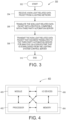
- FIG. 4 depicts a high-level block diagram of a computer that is dedicated to perform the functions described herein.
- the computer 400 comprises one or more hardware processor elements 402 (e.g., a central processing unit (CPU), a microprocessor, or a multi-core processor), a memory 404, e.g., random access memory (RAM) and/or read only memory (ROM), a module 405 for translating non-light related data packets into a protocol that is compatible with a third party automation server, and various input/output devices 406 (e.g., storage devices, including but not limited to, a tape drive, a floppy drive, a hard disk drive or a compact disk drive, a receiver, a transmitter, a speaker, a display, a speech synthesizer, an output port, an input port and a user input device (such as a keyboard, a keypad, a mouse, a microphone and the like)).
- hardware processor elements 402 e.g., a central processing unit (
- the computer may employ a plurality of processor elements.
- the computer may employ a plurality of processor elements.
- the method(s) as discussed above is implemented in a distributed or parallel manner for a particular illustrative example, i.e., the steps of the above method(s) or the entire method(s) are implemented across multiple or parallel computers, then the computer of this figure is intended to represent each of those multiple computers.
- one or more hardware processors can be utilized in supporting a virtualized or shared computing environment.
- the virtualized computing environment may support one or more virtual machines representing computers, servers, or other computing devices. In such virtualized virtual machines, hardware components such as hardware processors and computer-readable storage devices may be virtualized or logically represented.
- the present disclosure can be implemented in software and/or in a combination of software and hardware, e.g., using application specific integrated circuits (ASIC), a programmable logic array (PLA), including a field-programmable gate array (FPGA), or a state machine deployed on a hardware device, a computer or any other hardware equivalents, e.g., computer readable instructions pertaining to the method(s) discussed above can be used to configure a hardware processor to perform the steps, functions and/or operations of the above disclosed methods.
- ASIC application specific integrated circuits
- PDA programmable logic array
- FPGA field-programmable gate array
- instructions and data for the present module or process 405 for translating non-light related data packets into a protocol that is compatible with a third party automation server can be loaded into memory 404 and executed by hardware processor element 402 to implement the steps, functions or operations as discussed above in connection with the example method 300.
- a hardware processor executes instructions to perform "operations," this could include the hardware processor performing the operations directly and/or facilitating, directing, or cooperating with another hardware device or component (e.g., a co-processor and the like) to perform the operations.
- the processor executing the computer readable or software instructions relating to the above described method(s) can be perceived as a programmed processor or a specialized processor.
- the present module 405 for translating non-light related data packets into a protocol that is compatible with a third party automation server (including associated data structures) of the present disclosure can be stored on a tangible or physical (broadly non-transitory) computer-readable storage device or medium, e.g., volatile memory, non-volatile memory, ROM memory, RAM memory, magnetic or optical drive, device or diskette and the like.
- the computer-readable storage device may comprise any physical devices that provide the ability to store information such as data and/or instructions to be accessed by a processor or a computing device such as a computer or an application server.
- the embodiments of the present disclosure provide hardware and methods to connect the lighting network and data communication capabilities of the lighting network to a third party automation network.
- the hardware and processing capabilities of the third party automation network may be used to analyze the data collected by the lighting network using sub-routines provided by the lighting network service provider.
Landscapes
- Engineering & Computer Science (AREA)
- Computer Networks & Wireless Communication (AREA)
- Signal Processing (AREA)
- Health & Medical Sciences (AREA)
- Computing Systems (AREA)
- General Health & Medical Sciences (AREA)
- Medical Informatics (AREA)
- Circuit Arrangement For Electric Light Sources In General (AREA)
- Computer Security & Cryptography (AREA)
Claims (12)
- Beleuchtungsnetz-Steuerserver (102), der Folgendes umfasst:eine Kommunikationsschnittstelle (210) zum Empfangen von nicht lichtbezogenen Datenpaketen von einem Beleuchtungsnetz (104) und zum Kommunizieren mit einem Drittautomationsserver (118), wobei die Datenpakete mindestens eines von Folgendem umfassen: Heartbeat-Daten, Bewegungsdaten, Gebäudeinformationen oder von einem Sensor (116) erzeugten Videodaten;ein nichtflüchtiges computerlesbares Medium (204) zum Speichern von Subroutinen (206), Befehlen zum Ausführen eines Protokolladapters (208) und der von dem Sensor (116) erzeugten Datenpakete, wobei jede der Subroutinen (206) einen anderen Zusatzbefehl umfasst, der auf der Basis eines von dem Sensor (116) erzeugten Datentyps auf den Drittautomationsserver (118) heruntergeladen wird, um die von dem Sensor (116) erzeugten Datenpakete zu analysieren, um Software einer Drittsteuerung für eine bestimmte Anwendung zu modifizieren und eine Ausgabe für eine bestimmte Anwendung zu erzeugen; undeinen Prozessor (202), der kommunikativ mit der Kommunikationsschnittstelle (210) und dem nichtflüchtigen computerlesbaren Medium (204) gekoppelt ist, um den Protokolladapter (206) zum Übersetzen der Datenpakete von einem vom Beleuchtungsnetz (104) verwendeten Device Control Protocol-, DCP-, over-Ethernet-Protokoll auszuführen, um die Daten in ein mit dem Drittautomationsserver (118) kompatibles Protokollformat zu übersetzen, indem ein neuer Satz von übersetzten Daten erzeugt wird, der in dem Protokollformat ist, das von dem Drittautomationsserver (118) verstanden oder gelesen werden kann, und der neue Satz von übersetzten Daten über die Kommunikationsschnittstelle (210) zum Drittautomationsserver (118) zum Analysieren durch eine von dem Drittautomationsserver (118) heruntergeladene Subroutine der gespeicherten Subroutinen (206) übertragen wird.
- Beleuchtungsnetz-Steuerserver (102) nach Anspruch 1, der ferner Folgendes umfasst:
eine grafische Benutzeroberfläche (122) zum Betrachten, Auswählen und Herunterladen der Subroutinen (206). - Beleuchtungsnetz-Steuerserver (102) nach Anspruch 1, wobei die Datenpakete Sensordaten umfassen, die von mindestens einer Beleuchtungsvorrichtung (112) des Beleuchtungsnetzes (104) gesammelt und übertragen werden.
- Beleuchtungsnetz-Steuerserver (102) nach Anspruch 3, wobei die Sensordaten von einer externen Sensorvorrichtung (116) stammen.
- Beleuchtungsnetz-Steuerserver (102) nach Anspruch 1, wobei die Kommunikationsschnittstelle (210) die Datenpakete vom Beleuchtungsnetz (104) über ein Gateway (110) empfängt.
- Beleuchtungsnetz-Steuerserver (102) nach Anspruch 1, wobei das mit dem Drittautomationsserver (118) kompatible Protokoll mindestens eines von der folgenden umfasst: Ethernet/IP, BACnet/IP, ControlNet, Modbus oder ProfiNet.
- Verfahren (300), das Folgendes umfasst:Empfangen (304), durch einen Prozessor (202) eines Beleuchtungssystem-Steuerservers (102), eines nicht lichtbezogenen Sensordatenpakets von einem Beleuchtungsnetz (104) und Speichern des Sensordatenpakets in einem Speicher (204) des Beleuchtungssystem-Steuerservers (102), wobei das Sensordatenpaket mindestens eines von Folgendem umfasst: Heartbeat-Daten, Bewegungsdaten, Gebäudeinformationen oder von einem Sensor (116) erzeugten Videodaten; Übertragen, durch den Prozessor (202), einer Subroutine zu einem Drittautomationsserver (118), die auf dem Drittautomationsserver (118) zu installieren ist, als Reaktion auf eine Anforderung zum Herunterladen der Subroutine in Bezug auf das Analysieren des Sensordatenpakets, wobei die Subroutine aus einer Vielzahl von in dem Beleuchtungsnetz-Steuerserver (102) gespeicherten Subroutinen (206) ausgewählt wird und jede der Subroutinen (206) Zusatzbefehle umfasst, die auf der Basis eines von dem Sensor (116) erzeugten Datentyps heruntergeladen werden, um eine Software einer Drittsteuerung für eine bestimmte Anwendung zu modifizieren, um das vom Sensor (116) erzeugte Sensordatenpaket zu analysieren und eine Ausgabe für eine bestimmte Anwendung zu erzeugen;Übersetzen (306), durch den Prozessor (202), des Sensordatenpakets von einem Device Control Protocol-, DCP-, over-Ethernet-Protokoll, das von dem Beleuchtungsnetz (104) zum Übertragen der Daten in ein mit einem Drittautomationsserver (118) kompatibles Protokollformat über einen Protokolladapter (208) verwendet wird, wobei das Übersetzen das Erzeugen eines neuen Satzes von übersetzten Daten in dem Protokollformat umfasst, das von dem Drittautomationserver (118) verstanden oder gelesen werden kann, undÜbertragen (308), durch den Prozessor (202), des neuen Satzes von Daten, der in das vom Drittautomationsserver (118) verstandene Protokoll übersetzt wird, zu dem Drittautomationsserver (118) zur Analyse über die von dem Beleuchtungssystem-Steuerserver (102) heruntergeladene Subroutine (206).
- Verfahren nach Anspruch 7, wobei die Subroutine (206) aus mehreren verschiedenen Subroutinen (206) ausgewählt wird, die in einer grafischen Benutzeroberfläche (122) des Beleuchtungssystem-Steuerservers (102) angezeigt werden.
- Verfahren nach Anspruch 7, wobei das Sensordatenpaket von mindestens einer Beleuchtungsvorrichtung (112) des Beleuchtungsnetzes gesammelt und übertragen wird.
- Verfahren nach Anspruch 7, wobei das Sensordatenpaket von einer externen Sensorvorrichtung (116) stammt.
- Verfahren nach Anspruch 7, wobei das Sensordatenpaket in einem Device Control Protocol-, DCP-, over-Ethernet-Protokoll empfangen wird.
- Verfahren nach Anspruch 7, wobei das mit dem Drittautomationsserver (118) kompatible Protokoll mindestens eines der folgenden umfasst: Ethernet/IP, BACnet/IP, ControlNet, Modbus oder ProfiNet.
Applications Claiming Priority (2)
| Application Number | Priority Date | Filing Date | Title |
|---|---|---|---|
| US201662439702P | 2016-12-28 | 2016-12-28 | |
| PCT/US2017/068040 WO2018125765A1 (en) | 2016-12-28 | 2017-12-21 | Lighting automation network |
Publications (3)
| Publication Number | Publication Date |
|---|---|
| EP3563201A1 EP3563201A1 (de) | 2019-11-06 |
| EP3563201A4 EP3563201A4 (de) | 2020-08-12 |
| EP3563201B1 true EP3563201B1 (de) | 2023-11-29 |
Family
ID=62630216
Family Applications (1)
| Application Number | Title | Priority Date | Filing Date |
|---|---|---|---|
| EP17886901.2A Active EP3563201B1 (de) | 2016-12-28 | 2017-12-21 | Netzwerk für beleuchtungsautomation |
Country Status (4)
| Country | Link |
|---|---|
| US (1) | US11297168B2 (de) |
| EP (1) | EP3563201B1 (de) |
| AU (1) | AU2017386521B2 (de) |
| WO (1) | WO2018125765A1 (de) |
Families Citing this family (1)
| Publication number | Priority date | Publication date | Assignee | Title |
|---|---|---|---|---|
| DE102019116120A1 (de) * | 2019-06-13 | 2020-12-17 | Endress+Hauser Process Solutions Ag | Verfahren zum Bereitstellen eines digitalen Zwillings für ein nicht digitales Feldgerät der Automatisierungstechnik |
Family Cites Families (30)
| Publication number | Priority date | Publication date | Assignee | Title |
|---|---|---|---|---|
| JP3224745B2 (ja) * | 1996-07-09 | 2001-11-05 | 株式会社日立製作所 | 高信頼化ネットワークシステム及びサーバ切り替え方法 |
| US6892230B1 (en) * | 1999-06-11 | 2005-05-10 | Microsoft Corporation | Dynamic self-configuration for ad hoc peer networking using mark-up language formated description messages |
| EP1784752A4 (de) * | 2004-08-06 | 2009-02-25 | Thermo Fisher Scientific Inc | Verfahren und vorrichtung zur umgebungsüberwachung |
| US7539487B2 (en) * | 2006-01-09 | 2009-05-26 | Microsoft Corporation | Interfacing I/O devices with a mobile server |
| US7764167B2 (en) * | 2006-01-18 | 2010-07-27 | British Telecommunications Plc | Monitoring movement of an entity in an environment |
| US20080021963A1 (en) * | 2006-07-21 | 2008-01-24 | At&T Corp. | Content dissemination using a multi-protocol converter |
| KR100874652B1 (ko) * | 2007-06-26 | 2008-12-17 | 한국전자통신연구원 | 이기종 센서네트워크를 위한 통합 인터페이스 장치 및 그방법 |
| TWI334068B (en) | 2007-07-06 | 2010-12-01 | Chunghwa Telecom Co Ltd | Network-based lighting equipment remote monitoring and management system |
| US8576746B2 (en) * | 2008-06-04 | 2013-11-05 | Electronics And Telecommunications Research Institute | Sensor node identification method for hierarchical sensor network, and component therefor |
| JP5481819B2 (ja) * | 2008-09-30 | 2014-04-23 | 富士通株式会社 | サーバ管理装置及び情報処理システム、サーバ管理装置の制御方法並びにプログラム |
| US8276193B2 (en) * | 2008-10-02 | 2012-09-25 | International Business Machines Corporation | System for online compromise tool |
| US8738190B2 (en) * | 2010-01-08 | 2014-05-27 | Rockwell Automation Technologies, Inc. | Industrial control energy object |
| US8667100B2 (en) * | 2010-07-07 | 2014-03-04 | Comcast Interactive Media, Llc | Device communication, monitoring and control architecture and method |
| US9386668B2 (en) * | 2010-09-30 | 2016-07-05 | Ketra, Inc. | Lighting control system |
| US9235277B2 (en) * | 2010-12-03 | 2016-01-12 | Razer (Asia-Pacific) Pte Ltd. | Profile management method |
| US8368310B1 (en) * | 2012-03-23 | 2013-02-05 | Inncom International, Inc. | System and method for distributed lighting device control |
| US9411323B2 (en) * | 2012-04-18 | 2016-08-09 | Tekpea, Inc. | Home energy management system |
| US20160081166A1 (en) * | 2013-03-13 | 2016-03-17 | Inception Innovations, Inc. | Color-Changing Lighting Dynamic Control |
| US9531559B1 (en) * | 2013-03-15 | 2016-12-27 | SmartThings, Inc. | Secured device access in a device automation system |
| EP2976856B1 (de) * | 2013-03-26 | 2019-08-14 | Sensity Systems Inc. | Sensorknoten mit multicast-übertragungen in einem sensorischen beleuchtungsnetzwerk |
| KR20170117610A (ko) * | 2013-05-16 | 2017-10-23 | 콘비다 와이어리스, 엘엘씨 | 시맨틱 명명 모델 |
| US9980351B2 (en) * | 2013-08-12 | 2018-05-22 | Abl Ip Holding Llc | Lighting element-centric network of networks |
| US10940077B2 (en) * | 2013-10-28 | 2021-03-09 | Dimensional Industries, Inc. | Data acquisition and analysis of human sexual response using a personal massaging device |
| US20160021189A1 (en) * | 2014-07-17 | 2016-01-21 | Cluster Wireless Llc | Automatic pushing of m2m signal processing to network sensor edge |
| US20160088708A1 (en) * | 2014-09-18 | 2016-03-24 | Osram Sylvania Inc. | Wireless control of lighting systems |
| US10045427B2 (en) * | 2014-09-29 | 2018-08-07 | Philips Lighting Holding B.V. | System and method of autonomous restore point creation and restoration for luminaire controllers |
| US20160352577A1 (en) * | 2015-05-27 | 2016-12-01 | Nimbus 9, Inc. | Multiple gateway virtualization |
| US10211660B2 (en) * | 2016-02-08 | 2019-02-19 | Cree, Inc. | LED lighting device with adaptive profiles for controlling power consumption |
| US10310474B2 (en) * | 2016-02-11 | 2019-06-04 | Philip Wernersbach | System and method for monitoring and analyzing industrial operations |
| US10327314B1 (en) * | 2018-02-12 | 2019-06-18 | Merlot Laboratories Inc. | System for integrated remote control of wireless lighting device and wireless electric and electronic devices in wireless network environment |
-
2017
- 2017-12-21 AU AU2017386521A patent/AU2017386521B2/en active Active
- 2017-12-21 US US15/851,623 patent/US11297168B2/en active Active
- 2017-12-21 WO PCT/US2017/068040 patent/WO2018125765A1/en not_active Ceased
- 2017-12-21 EP EP17886901.2A patent/EP3563201B1/de active Active
Also Published As
| Publication number | Publication date |
|---|---|
| US11297168B2 (en) | 2022-04-05 |
| EP3563201A4 (de) | 2020-08-12 |
| WO2018125765A1 (en) | 2018-07-05 |
| AU2017386521B2 (en) | 2022-11-03 |
| CA3047823A1 (en) | 2018-07-05 |
| EP3563201A1 (de) | 2019-11-06 |
| AU2017386521A1 (en) | 2019-07-04 |
| US20180183902A1 (en) | 2018-06-28 |
Similar Documents
| Publication | Publication Date | Title |
|---|---|---|
| US10742680B2 (en) | Method of industrial data communication with dedicated physical channel isolation and a system applying the method | |
| US12566770B2 (en) | Centralized knowledge repository and data mining system | |
| EP2966617B1 (de) | System umfassend vorrichtung zur bilddatenerzeugung und tragbare endgerätevorrichtung | |
| RU2713072C2 (ru) | Единая система управления для буровых установок | |
| US10838381B2 (en) | Setting system, setting device, setting method, and setting program | |
| US20220356796A1 (en) | Systems and methods of providing operational surveillance, diagnostics and optimization of oilfield artificial lift systems | |
| US11818002B2 (en) | Remote wireless sensors and systems including remote wireless sensors | |
| WO2021050247A1 (en) | Connected controls infrastructure | |
| CN107251016A (zh) | 监视和控制用于生产钻石的多个机器的操作的系统及其方法 | |
| CN105468430A (zh) | 基于虚拟化技术的勘探应用云桌面构建方法 | |
| EP2801002B1 (de) | Vorrichtung und verfahren zur synchronisierung einer steuerlogik | |
| US20160352577A1 (en) | Multiple gateway virtualization | |
| US20160043896A1 (en) | Home network manager for home automation | |
| EP3563201B1 (de) | Netzwerk für beleuchtungsautomation | |
| EP3334097A1 (de) | Verfahren, kommunikationswebservice und server zur bereitstellung von netzwerkkommunikation zwischen bacnet-vorrichtungen | |
| CA3047823C (en) | Lighting automation network | |
| US11985022B2 (en) | Systems and methods for managing devices on a wireless communications networks | |
| CN111766838A (zh) | 用于一个或多个站点的基于共享数据中心的工业自动化系统 | |
| CN112953947A (zh) | 一种单片机安全网关的单向数据透明传输方法 | |
| EP4645766A1 (de) | Drahtlose schnittstelle für ein einpaar-ethernetnetzwerk in einem industriellen automatisierungssystem | |
| US12219352B2 (en) | Method of wireless monitoring system connection to distributed control system | |
| Kakne et al. | Home Automation & Application with Bolt IoT | |
| KR20160129264A (ko) | 서버의 기능을 갖는 전력변환장치 | |
| CN115688163A (zh) | 数据处理方法、系统、电子设备及计算机可读存储介质 | |
| WO2020027755A2 (en) | M2m communication and remote programming device for automation systems |
Legal Events
| Date | Code | Title | Description |
|---|---|---|---|
| STAA | Information on the status of an ep patent application or granted ep patent |
Free format text: STATUS: THE INTERNATIONAL PUBLICATION HAS BEEN MADE |
|
| PUAI | Public reference made under article 153(3) epc to a published international application that has entered the european phase |
Free format text: ORIGINAL CODE: 0009012 |
|
| STAA | Information on the status of an ep patent application or granted ep patent |
Free format text: STATUS: REQUEST FOR EXAMINATION WAS MADE |
|
| 17P | Request for examination filed |
Effective date: 20190722 |
|
| AK | Designated contracting states |
Kind code of ref document: A1 Designated state(s): AL AT BE BG CH CY CZ DE DK EE ES FI FR GB GR HR HU IE IS IT LI LT LU LV MC MK MT NL NO PL PT RO RS SE SI SK SM TR |
|
| AX | Request for extension of the european patent |
Extension state: BA ME |
|
| DAV | Request for validation of the european patent (deleted) | ||
| DAX | Request for extension of the european patent (deleted) | ||
| A4 | Supplementary search report drawn up and despatched |
Effective date: 20200715 |
|
| RIC1 | Information provided on ipc code assigned before grant |
Ipc: H04L 12/66 20060101ALI20200709BHEP Ipc: H05B 47/175 20200101ALI20200709BHEP Ipc: G05B 15/02 20060101AFI20200709BHEP Ipc: H04L 29/08 20060101ALI20200709BHEP |
|
| STAA | Information on the status of an ep patent application or granted ep patent |
Free format text: STATUS: EXAMINATION IS IN PROGRESS |
|
| 17Q | First examination report despatched |
Effective date: 20211025 |
|
| GRAP | Despatch of communication of intention to grant a patent |
Free format text: ORIGINAL CODE: EPIDOSNIGR1 |
|
| STAA | Information on the status of an ep patent application or granted ep patent |
Free format text: STATUS: GRANT OF PATENT IS INTENDED |
|
| P01 | Opt-out of the competence of the unified patent court (upc) registered |
Effective date: 20230524 |
|
| RIC1 | Information provided on ipc code assigned before grant |
Ipc: H04L 67/12 20220101ALI20230525BHEP Ipc: H04L 12/66 20060101ALI20230525BHEP Ipc: H05B 47/175 20200101ALI20230525BHEP Ipc: G05B 15/02 20060101AFI20230525BHEP |
|
| INTG | Intention to grant announced |
Effective date: 20230609 |
|
| GRAS | Grant fee paid |
Free format text: ORIGINAL CODE: EPIDOSNIGR3 |
|
| GRAA | (expected) grant |
Free format text: ORIGINAL CODE: 0009210 |
|
| STAA | Information on the status of an ep patent application or granted ep patent |
Free format text: STATUS: THE PATENT HAS BEEN GRANTED |
|
| AK | Designated contracting states |
Kind code of ref document: B1 Designated state(s): AL AT BE BG CH CY CZ DE DK EE ES FI FR GB GR HR HU IE IS IT LI LT LU LV MC MK MT NL NO PL PT RO RS SE SI SK SM TR |
|
| REG | Reference to a national code |
Ref country code: GB Ref legal event code: FG4D |
|
| REG | Reference to a national code |
Ref country code: CH Ref legal event code: EP |
|
| REG | Reference to a national code |
Ref country code: DE Ref legal event code: R096 Ref document number: 602017077101 Country of ref document: DE |
|
| REG | Reference to a national code |
Ref country code: IE Ref legal event code: FG4D |
|
| REG | Reference to a national code |
Ref country code: LT Ref legal event code: MG9D |
|
| REG | Reference to a national code |
Ref country code: NL Ref legal event code: MP Effective date: 20231129 |
|
| PG25 | Lapsed in a contracting state [announced via postgrant information from national office to epo] |
Ref country code: GR Free format text: LAPSE BECAUSE OF FAILURE TO SUBMIT A TRANSLATION OF THE DESCRIPTION OR TO PAY THE FEE WITHIN THE PRESCRIBED TIME-LIMIT Effective date: 20240301 |
|
| PG25 | Lapsed in a contracting state [announced via postgrant information from national office to epo] |
Ref country code: IS Free format text: LAPSE BECAUSE OF FAILURE TO SUBMIT A TRANSLATION OF THE DESCRIPTION OR TO PAY THE FEE WITHIN THE PRESCRIBED TIME-LIMIT Effective date: 20240329 |
|
| PG25 | Lapsed in a contracting state [announced via postgrant information from national office to epo] |
Ref country code: LT Free format text: LAPSE BECAUSE OF FAILURE TO SUBMIT A TRANSLATION OF THE DESCRIPTION OR TO PAY THE FEE WITHIN THE PRESCRIBED TIME-LIMIT Effective date: 20231129 |
|
| PG25 | Lapsed in a contracting state [announced via postgrant information from national office to epo] |
Ref country code: ES Free format text: LAPSE BECAUSE OF FAILURE TO SUBMIT A TRANSLATION OF THE DESCRIPTION OR TO PAY THE FEE WITHIN THE PRESCRIBED TIME-LIMIT Effective date: 20231129 |
|
| PG25 | Lapsed in a contracting state [announced via postgrant information from national office to epo] |
Ref country code: LT Free format text: LAPSE BECAUSE OF FAILURE TO SUBMIT A TRANSLATION OF THE DESCRIPTION OR TO PAY THE FEE WITHIN THE PRESCRIBED TIME-LIMIT Effective date: 20231129 Ref country code: IS Free format text: LAPSE BECAUSE OF FAILURE TO SUBMIT A TRANSLATION OF THE DESCRIPTION OR TO PAY THE FEE WITHIN THE PRESCRIBED TIME-LIMIT Effective date: 20240329 Ref country code: GR Free format text: LAPSE BECAUSE OF FAILURE TO SUBMIT A TRANSLATION OF THE DESCRIPTION OR TO PAY THE FEE WITHIN THE PRESCRIBED TIME-LIMIT Effective date: 20240301 Ref country code: ES Free format text: LAPSE BECAUSE OF FAILURE TO SUBMIT A TRANSLATION OF THE DESCRIPTION OR TO PAY THE FEE WITHIN THE PRESCRIBED TIME-LIMIT Effective date: 20231129 Ref country code: BG Free format text: LAPSE BECAUSE OF FAILURE TO SUBMIT A TRANSLATION OF THE DESCRIPTION OR TO PAY THE FEE WITHIN THE PRESCRIBED TIME-LIMIT Effective date: 20240229 |
|
| REG | Reference to a national code |
Ref country code: AT Ref legal event code: MK05 Ref document number: 1636768 Country of ref document: AT Kind code of ref document: T Effective date: 20231129 |
|
| PG25 | Lapsed in a contracting state [announced via postgrant information from national office to epo] |
Ref country code: NL Free format text: LAPSE BECAUSE OF FAILURE TO SUBMIT A TRANSLATION OF THE DESCRIPTION OR TO PAY THE FEE WITHIN THE PRESCRIBED TIME-LIMIT Effective date: 20231129 |
|
| PG25 | Lapsed in a contracting state [announced via postgrant information from national office to epo] |
Ref country code: SE Free format text: LAPSE BECAUSE OF FAILURE TO SUBMIT A TRANSLATION OF THE DESCRIPTION OR TO PAY THE FEE WITHIN THE PRESCRIBED TIME-LIMIT Effective date: 20231129 Ref country code: RS Free format text: LAPSE BECAUSE OF FAILURE TO SUBMIT A TRANSLATION OF THE DESCRIPTION OR TO PAY THE FEE WITHIN THE PRESCRIBED TIME-LIMIT Effective date: 20231129 Ref country code: PL Free format text: LAPSE BECAUSE OF FAILURE TO SUBMIT A TRANSLATION OF THE DESCRIPTION OR TO PAY THE FEE WITHIN THE PRESCRIBED TIME-LIMIT Effective date: 20231129 Ref country code: NO Free format text: LAPSE BECAUSE OF FAILURE TO SUBMIT A TRANSLATION OF THE DESCRIPTION OR TO PAY THE FEE WITHIN THE PRESCRIBED TIME-LIMIT Effective date: 20240229 Ref country code: NL Free format text: LAPSE BECAUSE OF FAILURE TO SUBMIT A TRANSLATION OF THE DESCRIPTION OR TO PAY THE FEE WITHIN THE PRESCRIBED TIME-LIMIT Effective date: 20231129 Ref country code: LV Free format text: LAPSE BECAUSE OF FAILURE TO SUBMIT A TRANSLATION OF THE DESCRIPTION OR TO PAY THE FEE WITHIN THE PRESCRIBED TIME-LIMIT Effective date: 20231129 Ref country code: HR Free format text: LAPSE BECAUSE OF FAILURE TO SUBMIT A TRANSLATION OF THE DESCRIPTION OR TO PAY THE FEE WITHIN THE PRESCRIBED TIME-LIMIT Effective date: 20231129 |
|
| PG25 | Lapsed in a contracting state [announced via postgrant information from national office to epo] |
Ref country code: DK Free format text: LAPSE BECAUSE OF FAILURE TO SUBMIT A TRANSLATION OF THE DESCRIPTION OR TO PAY THE FEE WITHIN THE PRESCRIBED TIME-LIMIT Effective date: 20231129 |
|
| PG25 | Lapsed in a contracting state [announced via postgrant information from national office to epo] |
Ref country code: AT Free format text: LAPSE BECAUSE OF FAILURE TO SUBMIT A TRANSLATION OF THE DESCRIPTION OR TO PAY THE FEE WITHIN THE PRESCRIBED TIME-LIMIT Effective date: 20231129 Ref country code: CZ Free format text: LAPSE BECAUSE OF FAILURE TO SUBMIT A TRANSLATION OF THE DESCRIPTION OR TO PAY THE FEE WITHIN THE PRESCRIBED TIME-LIMIT Effective date: 20231129 |
|
| PG25 | Lapsed in a contracting state [announced via postgrant information from national office to epo] |
Ref country code: SK Free format text: LAPSE BECAUSE OF FAILURE TO SUBMIT A TRANSLATION OF THE DESCRIPTION OR TO PAY THE FEE WITHIN THE PRESCRIBED TIME-LIMIT Effective date: 20231129 |
|
| PG25 | Lapsed in a contracting state [announced via postgrant information from national office to epo] |
Ref country code: SM Free format text: LAPSE BECAUSE OF FAILURE TO SUBMIT A TRANSLATION OF THE DESCRIPTION OR TO PAY THE FEE WITHIN THE PRESCRIBED TIME-LIMIT Effective date: 20231129 Ref country code: SK Free format text: LAPSE BECAUSE OF FAILURE TO SUBMIT A TRANSLATION OF THE DESCRIPTION OR TO PAY THE FEE WITHIN THE PRESCRIBED TIME-LIMIT Effective date: 20231129 Ref country code: RO Free format text: LAPSE BECAUSE OF FAILURE TO SUBMIT A TRANSLATION OF THE DESCRIPTION OR TO PAY THE FEE WITHIN THE PRESCRIBED TIME-LIMIT Effective date: 20231129 Ref country code: IT Free format text: LAPSE BECAUSE OF FAILURE TO SUBMIT A TRANSLATION OF THE DESCRIPTION OR TO PAY THE FEE WITHIN THE PRESCRIBED TIME-LIMIT Effective date: 20231129 Ref country code: EE Free format text: LAPSE BECAUSE OF FAILURE TO SUBMIT A TRANSLATION OF THE DESCRIPTION OR TO PAY THE FEE WITHIN THE PRESCRIBED TIME-LIMIT Effective date: 20231129 Ref country code: DK Free format text: LAPSE BECAUSE OF FAILURE TO SUBMIT A TRANSLATION OF THE DESCRIPTION OR TO PAY THE FEE WITHIN THE PRESCRIBED TIME-LIMIT Effective date: 20231129 Ref country code: CZ Free format text: LAPSE BECAUSE OF FAILURE TO SUBMIT A TRANSLATION OF THE DESCRIPTION OR TO PAY THE FEE WITHIN THE PRESCRIBED TIME-LIMIT Effective date: 20231129 Ref country code: AT Free format text: LAPSE BECAUSE OF FAILURE TO SUBMIT A TRANSLATION OF THE DESCRIPTION OR TO PAY THE FEE WITHIN THE PRESCRIBED TIME-LIMIT Effective date: 20231129 |
|
| REG | Reference to a national code |
Ref country code: CH Ref legal event code: PL |
|
| PG25 | Lapsed in a contracting state [announced via postgrant information from national office to epo] |
Ref country code: PT Free format text: LAPSE BECAUSE OF FAILURE TO SUBMIT A TRANSLATION OF THE DESCRIPTION OR TO PAY THE FEE WITHIN THE PRESCRIBED TIME-LIMIT Effective date: 20240401 |
|
| PG25 | Lapsed in a contracting state [announced via postgrant information from national office to epo] |
Ref country code: LU Free format text: LAPSE BECAUSE OF NON-PAYMENT OF DUE FEES Effective date: 20231221 |
|
| PG25 | Lapsed in a contracting state [announced via postgrant information from national office to epo] |
Ref country code: MC Free format text: LAPSE BECAUSE OF FAILURE TO SUBMIT A TRANSLATION OF THE DESCRIPTION OR TO PAY THE FEE WITHIN THE PRESCRIBED TIME-LIMIT Effective date: 20231129 |
|
| REG | Reference to a national code |
Ref country code: BE Ref legal event code: MM Effective date: 20231231 |
|
| PG25 | Lapsed in a contracting state [announced via postgrant information from national office to epo] |
Ref country code: PT Free format text: LAPSE BECAUSE OF FAILURE TO SUBMIT A TRANSLATION OF THE DESCRIPTION OR TO PAY THE FEE WITHIN THE PRESCRIBED TIME-LIMIT Effective date: 20240401 Ref country code: MC Free format text: LAPSE BECAUSE OF FAILURE TO SUBMIT A TRANSLATION OF THE DESCRIPTION OR TO PAY THE FEE WITHIN THE PRESCRIBED TIME-LIMIT Effective date: 20231129 Ref country code: LU Free format text: LAPSE BECAUSE OF NON-PAYMENT OF DUE FEES Effective date: 20231221 |
|
| REG | Reference to a national code |
Ref country code: DE Ref legal event code: R097 Ref document number: 602017077101 Country of ref document: DE |
|
| PLBE | No opposition filed within time limit |
Free format text: ORIGINAL CODE: 0009261 |
|
| STAA | Information on the status of an ep patent application or granted ep patent |
Free format text: STATUS: NO OPPOSITION FILED WITHIN TIME LIMIT |
|
| REG | Reference to a national code |
Ref country code: IE Ref legal event code: MM4A |
|
| PG25 | Lapsed in a contracting state [announced via postgrant information from national office to epo] |
Ref country code: IE Free format text: LAPSE BECAUSE OF NON-PAYMENT OF DUE FEES Effective date: 20231221 |
|
| PG25 | Lapsed in a contracting state [announced via postgrant information from national office to epo] |
Ref country code: BE Free format text: LAPSE BECAUSE OF NON-PAYMENT OF DUE FEES Effective date: 20231231 |
|
| PG25 | Lapsed in a contracting state [announced via postgrant information from national office to epo] |
Ref country code: CH Free format text: LAPSE BECAUSE OF NON-PAYMENT OF DUE FEES Effective date: 20231231 |
|
| PG25 | Lapsed in a contracting state [announced via postgrant information from national office to epo] |
Ref country code: SI Free format text: LAPSE BECAUSE OF FAILURE TO SUBMIT A TRANSLATION OF THE DESCRIPTION OR TO PAY THE FEE WITHIN THE PRESCRIBED TIME-LIMIT Effective date: 20231129 |
|
| PG25 | Lapsed in a contracting state [announced via postgrant information from national office to epo] |
Ref country code: SI Free format text: LAPSE BECAUSE OF FAILURE TO SUBMIT A TRANSLATION OF THE DESCRIPTION OR TO PAY THE FEE WITHIN THE PRESCRIBED TIME-LIMIT Effective date: 20231129 Ref country code: IE Free format text: LAPSE BECAUSE OF NON-PAYMENT OF DUE FEES Effective date: 20231221 Ref country code: CH Free format text: LAPSE BECAUSE OF NON-PAYMENT OF DUE FEES Effective date: 20231231 Ref country code: BE Free format text: LAPSE BECAUSE OF NON-PAYMENT OF DUE FEES Effective date: 20231231 |
|
| 26N | No opposition filed |
Effective date: 20240830 |
|
| PG25 | Lapsed in a contracting state [announced via postgrant information from national office to epo] |
Ref country code: FI Free format text: LAPSE BECAUSE OF FAILURE TO SUBMIT A TRANSLATION OF THE DESCRIPTION OR TO PAY THE FEE WITHIN THE PRESCRIBED TIME-LIMIT Effective date: 20231129 |
|
| PG25 | Lapsed in a contracting state [announced via postgrant information from national office to epo] |
Ref country code: CY Free format text: LAPSE BECAUSE OF FAILURE TO SUBMIT A TRANSLATION OF THE DESCRIPTION OR TO PAY THE FEE WITHIN THE PRESCRIBED TIME-LIMIT; INVALID AB INITIO Effective date: 20171221 |
|
| PG25 | Lapsed in a contracting state [announced via postgrant information from national office to epo] |
Ref country code: HU Free format text: LAPSE BECAUSE OF FAILURE TO SUBMIT A TRANSLATION OF THE DESCRIPTION OR TO PAY THE FEE WITHIN THE PRESCRIBED TIME-LIMIT; INVALID AB INITIO Effective date: 20171221 |
|
| PG25 | Lapsed in a contracting state [announced via postgrant information from national office to epo] |
Ref country code: TR Free format text: LAPSE BECAUSE OF FAILURE TO SUBMIT A TRANSLATION OF THE DESCRIPTION OR TO PAY THE FEE WITHIN THE PRESCRIBED TIME-LIMIT Effective date: 20231129 |
|
| PGFP | Annual fee paid to national office [announced via postgrant information from national office to epo] |
Ref country code: DE Payment date: 20251118 Year of fee payment: 9 |
|
| PGFP | Annual fee paid to national office [announced via postgrant information from national office to epo] |
Ref country code: GB Payment date: 20251113 Year of fee payment: 9 |
|
| PGFP | Annual fee paid to national office [announced via postgrant information from national office to epo] |
Ref country code: FR Payment date: 20251111 Year of fee payment: 9 |