EP3563473B1 - Module de génération d'impulsions électriques avec condensateur stockage, diode de roue libre et reset de transformateur pendant la phase de chargement - Google Patents
Module de génération d'impulsions électriques avec condensateur stockage, diode de roue libre et reset de transformateur pendant la phase de chargement Download PDFInfo
- Publication number
- EP3563473B1 EP3563473B1 EP17835836.2A EP17835836A EP3563473B1 EP 3563473 B1 EP3563473 B1 EP 3563473B1 EP 17835836 A EP17835836 A EP 17835836A EP 3563473 B1 EP3563473 B1 EP 3563473B1
- Authority
- EP
- European Patent Office
- Prior art keywords
- transformer
- electrical pulse
- charging current
- protection unit
- switch unit
- Prior art date
- Legal status (The legal status is an assumption and is not a legal conclusion. Google has not performed a legal analysis and makes no representation as to the accuracy of the status listed.)
- Active
Links
Images

Classifications
-
- H—ELECTRICITY
- H03—ELECTRONIC CIRCUITRY
- H03K—PULSE TECHNIQUE
- H03K3/00—Circuits for generating electric pulses; Monostable, bistable or multistable circuits
- H03K3/02—Generators characterised by the type of circuit or by the means used for producing pulses
- H03K3/53—Generators characterised by the type of circuit or by the means used for producing pulses by the use of an energy-accumulating element discharged through the load by a switching device controlled by an external signal and not incorporating positive feedback
- H03K3/57—Generators characterised by the type of circuit or by the means used for producing pulses by the use of an energy-accumulating element discharged through the load by a switching device controlled by an external signal and not incorporating positive feedback the switching device being a semiconductor device
-
- H—ELECTRICITY
- H02—GENERATION; CONVERSION OR DISTRIBUTION OF ELECTRIC POWER
- H02M—APPARATUS FOR CONVERSION BETWEEN AC AND AC, BETWEEN AC AND DC, OR BETWEEN DC AND DC, AND FOR USE WITH MAINS OR SIMILAR POWER SUPPLY SYSTEMS; CONVERSION OF DC OR AC INPUT POWER INTO SURGE OUTPUT POWER; CONTROL OR REGULATION THEREOF
- H02M1/00—Details of apparatus for conversion
- H02M1/32—Means for protecting converters other than automatic disconnection
-
- H—ELECTRICITY
- H02—GENERATION; CONVERSION OR DISTRIBUTION OF ELECTRIC POWER
- H02H—EMERGENCY PROTECTIVE CIRCUIT ARRANGEMENTS
- H02H9/00—Emergency protective circuit arrangements for limiting excess current or voltage without disconnection
- H02H9/001—Emergency protective circuit arrangements for limiting excess current or voltage without disconnection limiting speed of change of electric quantities, e.g. soft switching on or off
- H02H9/002—Emergency protective circuit arrangements for limiting excess current or voltage without disconnection limiting speed of change of electric quantities, e.g. soft switching on or off limiting inrush current on switching on of inductive loads subjected to remanence, e.g. transformers
-
- H—ELECTRICITY
- H02—GENERATION; CONVERSION OR DISTRIBUTION OF ELECTRIC POWER
- H02M—APPARATUS FOR CONVERSION BETWEEN AC AND AC, BETWEEN AC AND DC, OR BETWEEN DC AND DC, AND FOR USE WITH MAINS OR SIMILAR POWER SUPPLY SYSTEMS; CONVERSION OF DC OR AC INPUT POWER INTO SURGE OUTPUT POWER; CONTROL OR REGULATION THEREOF
- H02M1/00—Details of apparatus for conversion
- H02M1/40—Means for preventing magnetic saturation
-
- H—ELECTRICITY
- H02—GENERATION; CONVERSION OR DISTRIBUTION OF ELECTRIC POWER
- H02M—APPARATUS FOR CONVERSION BETWEEN AC AND AC, BETWEEN AC AND DC, OR BETWEEN DC AND DC, AND FOR USE WITH MAINS OR SIMILAR POWER SUPPLY SYSTEMS; CONVERSION OF DC OR AC INPUT POWER INTO SURGE OUTPUT POWER; CONTROL OR REGULATION THEREOF
- H02M3/00—Conversion of DC power input into DC power output
- H02M3/22—Conversion of DC power input into DC power output with intermediate conversion into AC
- H02M3/24—Conversion of DC power input into DC power output with intermediate conversion into AC by static converters
- H02M3/28—Conversion of DC power input into DC power output with intermediate conversion into AC by static converters using discharge tubes with control electrode or semiconductor devices with control electrode to produce the intermediate AC
- H02M3/325—Conversion of DC power input into DC power output with intermediate conversion into AC by static converters using discharge tubes with control electrode or semiconductor devices with control electrode to produce the intermediate AC using devices of a triode or a transistor type requiring continuous application of a control signal
- H02M3/335—Conversion of DC power input into DC power output with intermediate conversion into AC by static converters using discharge tubes with control electrode or semiconductor devices with control electrode to produce the intermediate AC using devices of a triode or a transistor type requiring continuous application of a control signal using semiconductor devices only
Definitions
- the present invention generally relates to the field of electrical systems. Specifically, the present invention relates to an arrangement comprising an electrical pulse generating module configured to generate at least one electrical pulse.
- Electrical pulses may be employed in a variety of applications, such as, for example, radar systems, particle accelerators, sterilization equipment, high-energy lasers, microwave systems, or medical devices. In such and other applications it may be desired or required to deliver a one or more electrical pulses to a load.
- Systems or circuits which are employed for generating electrical pulses may be referred to as power modulators.
- Power modulators may employ a pulse transformer in order to obtain the required or desired energy of the electrical pulses. In some applications it may be desired or even required with a capability of providing electrical pulses to the pulse transformer which have a relatively high power and/or a relatively high frequency.
- An electrical pulse generating module in a power modulator may employ a power supply and an electrical energy storage module that can be charged or discharged.
- the electrical energy storage module may for example comprise a capacitor or several capacitors (e.g., a capacitor bank). Electrical pulses may be generated by repeatedly or cyclically performing charging and discharging of the electrical energy storage module, wherein when the electrical energy storage module is discharged, an electrical pulse is generated which may be received by a transformer (e.g., a voltage step-up transformer) connected to a load. Possibly, the electrical pulse may be delivered or conveyed directly to the load.
- a transformer e.g., a voltage step-up transformer
- a switch or switching device may be included in the electrical pulse generating module, which may selectively electrically connect or disconnect a power supply with the electrical energy storage module.
- the electrical energy storage module should be charged again in preparation for the next electrical pulse, upon which the switch or switching device may be switched into an open, or non-conducting state. Due to the sudden disappearance of current when an electrical pulse is terminated, flyback may possibly occur in the electrical pulse generating module. Such flyback may damage or even destroy, e.g., the switch or switching device due to the generally high voltage of the electrical pulses which are generated.
- a flyback protection unit may electrically connected to the switch or switching device for protection thereof against flyback upon the switch or switching device being opened.
- the transformer core should preferably be reset to its proper magnetic operating point, for example by removing all, or substantially all, energy from the transformer core.
- the transformer core may not be demagnetized when the next electrical pulse begins, but may for example be reset to a magnetic operating point in which the core is magnetized so as to exhibit a negative magnetic field strength.
- the magnetic field strength of the transformer core can vary between -B 1 and B 1 , where B 1 > 0, the transformer core may be reset (or 'biased') prior to the next electrical pulse begins so that it has a magnetic field strength -B 1 .
- the 'available' operating range of the transformer before saturation of the transformer core possibly may occur could then hence be 2B 1 .
- the full - or a substantially full - operating range of the transformer may be available for the next electrical pulse that is received by the transformer.
- a transformer reset power supply may be employed for supplying a current to the transformer for resetting the transformer core after an electrical pulse has been terminated and prior to the next electrical pulse.
- a charging current (which, e.g., may be provided by a power supply included in the electrical pulse generating module) present in the electrical pulse generating module during the charging of the electrical energy storage module may be directed, or conveyed, via the transformer, and may in so doing contribute to the resetting of the transformer core (i.e., in addition to the resetting of the transformer core carried out by means of the transformer reset power supply). It has further been found by the inventor that by employing the charging current to so that it makes a contribution to the resetting of the transformer core, it may be possible to provide the transformer with electrical pulses which have a relatively high frequency.
- a concern of the present invention is to provide an arrangement comprising an electrical pulse generating module configured to generate at least one electrical pulse and a transformer for receiving the at least one electrical pulse generated by the at least one electrical pulse generating module, which electrical pulse generating module may facilitate or allow for providing electrical pulses to the transformer which have a relatively high frequency.
- an arrangement comprising an electrical pulse generating module configured to generate at least one electrical pulse, and a transformer electrically connected to the electrical pulse generating module and configured to receive the at least one electrical pulse generated by the at least one electrical pulse generating module.
- the electrical pulse generating module comprises a power supply and an electrical energy storage module that can be charged or discharged.
- the electrical energy storage module is electrically connected to the transformer.
- the electrical pulse generating module comprises a switch unit that is controllably switchable between at least a conducting state and a non-conducting state.
- the switch unit is electrically connected to the power supply and the electrical energy storage module, respectively, such that when the switch unit is switched into the non-conducting state, the power supply charges the electrical energy storage module (partially or completely) by way of a charging current supplied by the power supply, and when the switch unit is switched into the conducting state, the electrical energy storage module is discharged (partially or completely) so as to create an electrical pulse to be received by the transformer.
- the arrangement comprises a flyback protection unit electrically connected to the switch unit and configured to protect the switch unit against flyback upon the switch unit being switched into the non-conducting state.
- the flyback protection unit forms a current path that bypasses the transformer.
- the flyback protection unit is configured such that a relation between the voltage drop across the flyback protection unit for the charging current and the voltage drop across the transformer for the charging current is such so as to cause the charging current to be directed (or conveyed, or routed) via the transformer at least to some extent.
- an arrangement comprising an electrical pulse generating module configured to generate at least one electrical pulse, and a transformer electrically connected to the electrical pulse generating module and configured to receive the at least one electrical pulse generated by the at least one electrical pulse generating module.
- the electrical pulse generating module comprises a power supply and an electrical energy storage module that can be charged or discharged.
- the electrical energy storage module is electrically connected to the transformer.
- the electrical pulse generating module comprises a switch unit that is controllably switchable between at least a conducting state and a non-conducting state.
- the switch unit is electrically connected to the power supply and the electrical energy storage module, respectively, such that the power supply charges the electrical energy storage module (partially or completely) by way of a charging current supplied by the power supply, or the electrical energy storage module is discharged (partially or completely) so as to create an electrical pulse to be received by the transformer, based on switching of the at least one switch unit between at least the conducting state and the non-conducting state thereof.
- the switch unit may be electrically connected to the power supply and the electrical energy storage module, respectively, such that when the switch unit is switched into the non-conducting state, the power supply charges the electrical energy storage module by way of a charging current supplied by the power supply, and when the switch unit is switched into the conducting state, the electrical energy storage module is discharged so as to create an electrical pulse to be received by the transformer.
- the arrangement comprises a flyback protection unit electrically connected to the switch unit and configured to protect the switch unit against flyback upon the switch unit being switched into the non-conducting state.
- the flyback protection unit forms a current path that bypasses the transformer.
- the flyback protection unit is configured such that a relation between the voltage drop across the flyback protection unit for the charging current and the voltage drop across the transformer for the charging current is such so as to cause the charging current to be directed (or conveyed, or routed) via the transformer at least to some extent.
- At least a part or portion of the charging current may be directed via the transformer.
- the flyback protection unit such that the voltage drop across the flyback protection unit for the charging current has a selected value relatively to a value of the voltage drop across the transformer for the charging current, at least a part or portion of the charging current may be directed via the transformer.
- the flyback protection unit forms a current path in the electrical pulse generating module, which current path bypasses the transformer (for example, so that current in the electrical pulse generating module may not be directed via, or pass, the transformer when going through the current path formed by the flyback protection unit).
- the flyback protection unit forms a current path by which current may bypass the transformer when the power supply charges the electrical energy storage module.
- the flyback protection unit such that a relation between the voltage drop across the flyback protection unit for the charging current and the voltage drop across the transformer (or voltage, e.g., a voltage over at least one (primary) winding of the transformer) for the charging current is such so as to cause the charging current to be directed via the transformer at least to some extent, at least a part or portion of the charging current may be caused to be directed via the transformer, and not only via the current path formed by the flyback protection unit. By at least a part or portion of the charging current being directed via the transformer, the charging current may contribute to the resetting of a core of the transformer.
- the voltage drop across the flyback protection unit for the charging current may determine the voltage over the transformer (e.g., the voltage over at least one (primary) winding of the transformer), which in turn may govern the extent to which the part or portion of the charging current that is directed via the transformer contributes to the resetting of the core.
- the electrical pulse generating module of the arrangement may facilitate or allow for providing electrical pulses to the transformer which have a relatively high frequency.
- the flyback protection unit may have to be configured so as to exhibit a larger voltage drop across the flyback protection unit (for the charging current) than what might be sufficient for achieving a sufficient flyback protection functionality or capacity for the switch unit.
- any transformer reset power supply which may be employed for supplying a current to the transformer for resetting the core of the transformer, might be required to have a smaller capacity with regard to, e.g., magnitude of its output current, as compared to if the charging current would not be employed to make it contribute to the resetting of the core of the transformer.
- the flyback protection unit may possibly be configured such that the voltage drop across the flyback protection unit for the charging current may be larger than the voltage drop across the transformer for the charging current. Also, the charging current could possibly be directed via the transformer to a greater extent than via the current path formed by the flyback protection unit.
- the flyback protection unit may be configured such that a relation between the voltage drop across the flyback protection unit for the charging current and the voltage drop across the transformer for the charging current is such so as to cause the charging current to be directed via the transformer, but not (or substantially not) via the current path formed by the flyback protection unit.
- the charging current may possibly be caused to altogether avoid the current path formed by the flyback protection unit.
- a very small part or portion of the charging current could possibly still be directed via the current path formed by the flyback protection unit.
- the electrical energy storage module may for example comprise at least one capacitor. Possibly, the electrical energy storage module may comprise several capacitors, e.g., a capacitor bank.
- the transformer may be electrically connected to the electrical pulse generating module for example by way of at least one winding of the transformer being electrically connected to the electrical pulse generating module.
- the at least one winding of the transformer may be configured to receive the at least one electrical pulse generated by the at least one electrical pulse generating module.
- the charging current may be directed via the transformer by means of the charging current being conveyed through the at least one winding of the transformer.
- the switch unit may for example comprise one or more solid-state semiconductor switching devices with turn-on and turn-off capability, such as, for example, at least one Integrated Gate-Commutated Transistor (IGCT), metal oxide semiconductor field effect transistor (MOSFET), gate turn-off thyristor (GTO) and/or Insulated-Gate Bipolar Transistor (IGBT), but is not limited thereto.
- IGCT Integrated Gate-Commutated Transistor
- MOSFET metal oxide semiconductor field effect transistor
- GTO gate turn-off thyristor
- IGBT Insulated-Gate Bipolar Transistor
- the power supply of the electrical pulse generating module may comprise a power converter.
- the power supply of the electrical pulse generating module may comprise or be connectable to an Alternating Current (AC) source, and may further comprise a rectifier for converting AC from the AC source into Direct Current (DC) which can be used to charge the electrical energy storage module.
- AC Alternating Current
- DC Direct Current
- a non-conducting state of the switch unit it is meant a state where there is no or only very little conduction of current through the switch unit.
- the switch unit may be switchable so as to stop, or at least substantially stop, the switch unit from conducting current through the switch unit.
- flyback it is meant a sudden voltage spike that may be seen across an inductive load (e.g., corresponding to the inductance of one or more electrical conductors connecting the electrical energy storage module and the transformer) that has been energized when the inductive load's supply current (e.g., the discharge from the electrical energy storage module) is suddenly reduced or interrupted.
- inductive load e.g., corresponding to the inductance of one or more electrical conductors connecting the electrical energy storage module and the transformer
- the flyback protection unit may for example comprise at least one series connection of diodes.
- the diodes may be referred to as free-wheeling diodes.
- the voltage drop across a series connection of diodes is the sum of the voltage drop across each of the diodes in the series connection of diodes.
- the number of diodes in the at least one series connection of diodes may be chosen such that the voltage drop across the at least one series connection of diodes for the charging current is larger than the voltage drop across the transformer for the charging current.
- the voltage drop across or over the flyback protection unit may refer to the voltage drop, e.g., the forward voltage drop, across the series connected diodes.
- the at least one series connection of diodes may for example comprise at least four diodes connected in series.
- the at least one series connection of diodes could possibly comprise at least five diodes connected in series, or at least six or more diodes connected in series.
- the flyback protection unit may comprise at least two series connections of diodes wherein two or more of the series connections of diodes may be electrically connected in parallel.
- any one or each of the diodes which may be included in the flyback protection unit may comprise, for example, in principle any type of semiconductor diode.
- the flyback protection unit may comprise one or more Zener diodes.
- the transformer may comprise at least one core.
- the arrangement may comprise a transformer reset power supply, electrically connected to the transformer and configured to supply a current to the transformer for resetting the at least one core of the transformer prior to an electrical pulse generated by the at least one electrical pulse generating module being received by the transformer.
- the charging current directed via the transformer may contribute to the resetting of the at least one core of the transformer.
- the transformer may comprise at least one reset winding arranged so as to at least in part surround the at least one core of the transformer.
- the transformer reset power supply may be electrically connected to the transformer by way of the at least one reset winding for supplying a current to the transformer for resetting the at least one core of the transformer.
- resetting a core of a transformer it is meant to reset the core to its appropriate magnetic operating point. This may entail removing all, or substantially all, energy from the core.
- the transformer core may not be demagnetized, but may be reset to a magnetic operating point in which the core is magnetized so as to exhibit a negative magnetic field strength.
- the magnetic field strength of the transformer core can vary between -B 1 and B 1 , where Bi > 0, the transformer core may be reset that it has a magnetic field strength -B 1 .
- the operating range of the transformer before saturation of the transformer core may occur could then hence be 2B 1 .
- Resetting of a core of a transformer may in alternative be referred to as applying a bias to the core. By resetting the at least one core of the transformer after each electrical pulse, the full or a substantially full operating range of the transformer may be available for the next electrical pulse received by the transformer.
- the flyback protection unit and the switch unit may for example be electrically connected in parallel.
- the flyback protection unit and the transformer may for example be electrically connected in parallel.
- the arrangement may comprise at least one additional switch unit (i.e., in addition to the above-mentioned switch unit that is electrically connected to the power supply and the electrical energy storage module).
- the at least one additional switch unit may be arranged in the current path formed by the flyback protection unit.
- the at least one additional switch unit may be controllably switchable between at least a conducting state and a non-conducting state, and may for example comprise one or more solid-state semiconductor switching devices with turn-on and turn-off capability, such as, for example, at least one IGCT, MOSFET, GTO and/or IGBT, but is not limited thereto.
- the at least one additional switch unit may for example be electrically connected in series with the flyback protection unit.
- the at least one additional switch unit may be operated so as to be switched into the non-conducting state thereof during the charging of the electrical energy storage module.
- the flyback protection unit may possibly be configured such that a relation between the voltage drop across the flyback protection unit for the charging current and the voltage drop across the transformer for the charging current is such so as to cause the charging current to be directed via the transformer, but not (or substantially not) via the current path formed by the flyback protection unit.
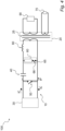
- FIG 1 is a schematic view of an arrangement 100 according to an embodiment of the present invention.
- the arrangement 100 comprises an electrical pulse generating module 10 which is configured to generate at least one electrical pulse.
- the arrangement 100 comprises a transformer 20.
- the transformer 20 is electrically connected to the electrical pulse generating module 10.
- the transformer 20 is configured to receive one or more electrical pulses generated by the at least one electrical pulse generating module 10.
- the arrangement 100 may - in accordance with one or more embodiments of the present invention - comprise several electrical pulse generating modules, each of which may be electrically connected with the transformer 20.
- the electrical pulse generating module 10 may be configured to generate a plurality of pulses by repeatedly or cyclically performing charging and discharging of an electrical energy storage module, such as, for example, a capacitor or a capacitor bank. Each time the electrical energy storage module is discharged, an electrical pulse may be generated which may be received by the transformer 20.
- the transformer 20 may for example include or be constituted by a voltage step-up transformer. In accordance with the embodiment of the present invention illustrated in Figure 1 , the transformer 20 may be connected to a load 90, which hence may receive the electrical pulse via the transformer 20.
- the electrical pulse generating module 10 comprises a power supply 30 and an electrical energy storage module 40 that can be charged or discharged.
- the power supply 30 may comprise a power converter.
- the power supply 30 could comprise or be connectable to an AC source (not shown in Figure 1 ), and could comprise a rectifier (not shown in Figure 1 ) for converting AC from the AC source into DC, which may be employed to charge the electrical energy storage module 40.
- the electrical energy storage module 40 is electrically connected to the transformer 20.
- the electrical energy storage module 40 may for example comprise a capacitor, or several capacitors, e.g., arranged in a capacitor bank.
- the electrical energy storage module 40 is not limited to being capacitor-based, but it could in alternative or in addition be based on another or other types of electrical energy storage means.
- the electrical pulse generating module 10 comprises a switch unit 50.
- the switch unit 50 is controllably switchable between at least a conducting state and a non-conducting state of the switch unit 50.
- the switch unit 50 could for example comprise one or more solid-state semiconductor switching devices, such as, for example, at least one IGCT, MOSFET, GTO and/or IGBT, and/or another or other types of electronic switching devices with turn-on and turn-off capability.
- the switch unit 50 is electrically connected to the power supply 30 and the electrical energy storage module 40, respectively, such that when the switch unit 50 is switched into the non-conducting state, the power supply 30 charges the electrical energy storage module 40 by way of a charging current supplied by the power supply 30 to the electrical energy storage module 40, and when the switch unit 50 is switched into the conducting state, the electrical energy storage module 40 is discharged so as to create an electrical pulse, which can be received by the transformer 20.
- the transformer 20 may comprise at least one winding by which the transformer 20 may be electrically connected to the electrical pulse generating module 10.
- the transformer 20 may be electrically connected to the electrical pulse generating module 10 by way of two terminals thereof, as illustrated in Figure 1 .
- the transformer 20 may comprise two windings by which the transformer 20 may be electrically connected to the electrical pulse generating module.
- the number of windings of the transformer 20 by which the transformer 20 may be electrically connected to the electrical pulse generating module 10 is not limited to two, but may for example be larger than two.
- the winding(s) of the transformer 20 may be configured to receive the electrical pulses generated by the electrical pulse generating module 10.
- the charging current that is supplied by the power supply 30 when the switch unit 50 is switched into the non-conducting state may flow out of the power supply 30 via the conductor of the two conductors connected to the power supply 30 that is uppermost in Figure 1 , and return to the power supply 30 via the conductor of the two conductors connected to the power supply 30 that is lowermost in Figure 1 , as indicated by the arrows IC in Figure 1 .
- the two above-mentioned conductors may for example be connected to two terminals of the power supply 30, as illustrated in Figure 1 .
- an electrical pulse which is generated when the electrical energy storage module 40 is discharged upon the switch unit 50 being switched into the conducting state, may flow in the direction indicated by the arrow IP in Figure 1 .
- the duration of an electrical pulse may for example be 1 ms or about 1 ms, but is not limited thereto, and could be longer, or shorter.
- the arrangement 100 e.g., the electrical pulse generating module 10, comprises a flyback protection unit 60.
- the flyback protection unit 60 is electrically connected to the switch unit 50.
- the flyback protection unit 60 is configured to protect the switch unit 50 against flyback, e.g., when the switch unit 50 is switched into the non-conducting state thereof.
- the switch unit 50 may during the delivery of an electrical pulse have been switched into the conducting state for such a period of time that an inductance 80 has been fully energized.
- the inductance 80 may possibly not be a separate electrical component in the electrical pulse generating module 10, but could for example be the inductance of the conductor between the flyback protection circuit 60 and the transformer 20.
- the switch unit 50 When the switch unit 50 is switched into the non-conducting state, the discharge from the electrical energy storage module 40 may be suddenly reduced or interrupted. This may entail that a surge of voltage, or voltage spike, is created, which in turn may cause an overvoltage condition in the switch unit 50 that may damage or even destroy the switch unit 50.
- the flyback protection unit 60 may protect against such an overvoltage condition in the switch unit 50 by allowing for the inductance 80 to draw current from itself in a continuous circuit until the energy in the inductance 80 has been sufficiently dissipated, e.g., by means of resistive losses in conductors in the electrical pulse generating module 10.
- the flyback protection unit 60 forms a current path, schematically indicated by reference numeral 65 in Figure 1 , which bypasses the transformer 20. This may for example be implemented by means of an electrical configuration such as illustrated in Figure 1 . In accordance with the embodiment of the present invention illustrated in Figure 1 , the flyback protection unit 60 and the switch unit 50 may be electrically connected in parallel, and the flyback protection unit 60 and the transformer 20 may in addition or alternatively be electrically connected in parallel.
- the flyback protection unit 60 is configured such that a relation between the voltage drop across the flyback protection unit 60 for the charging current and the voltage drop across the transformer 20 for the charging current is such so as to cause the charging current, which is supplied by the power supply 30 when the switch unit 50 is switched into the non-conducting state, to be directed via the transformer 20 at least to some extent.
- the charging current or at least a part or portion thereof, may be directed via the transformer 20 by means of the charging current or at least a part or portion thereof being conveyed through the winding(s) of the transformer 20.
- the voltage drop across the flyback protection unit 60 for the charging current may determine the voltage over the transformer 20 (e.g., the voltage over at least one (primary) winding of the transformer 20), which in turn may govern the extent to which the part or portion of the charging current that is directed via the transformer 20 contributes to the resetting of the core.
- the flyback protection unit 60 may be configured such that the voltage drop across the flyback protection unit 60 for the charging current is larger than the voltage drop across the transformer 20 for the charging current, so as to cause the charging current to be directed via the transformer 20, but not (or only to a very small extent) via the current path 65 formed by the flyback protection unit 60.
- the charging current may possibly be caused, by the configuration of the flyback protection unit 60 relatively to the transformer 20, to altogether avoid the current path 65 formed by the flyback protection unit 60.
- a configuration of the flyback protection unit 60 as described in the foregoing - i.e. such that a relation between the voltage drop across the flyback protection unit 60 for the charging current and the voltage drop across the transformer 20 for the charging current is such so as to cause the charging current to be directed via the transformer 20 at least to some extent - may be achieved in different manners.
- the flyback protection unit 60 may comprise several diodes arranged so as to achieve a configuration of the flyback protection unit 60 such that a relation between the voltage drop across the flyback protection unit 60 for the charging current and the voltage drop across the transformer 20 for the charging current is such so as to cause at least a part or portion of the charging current to be directed via the transformer 20.
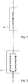
- FIGS 2 and 3 are schematic views of flyback protection units 60 in accordance with different embodiments of the present invention.
- the upper and lower conductors (of which only parts are shown) extending into the flyback protection unit 60 illustrated in the respective ones of Figures 2 and 3 correspond to the upper and lower conductors, respectively, extending into the flyback protection unit 60 illustrated in Figure 1 .
- the flyback protection unit 60 may, in accordance with an embodiment of the present invention, comprise a series connection of diodes.
- the number of diodes in the series connection of diodes may possibly be chosen such that the voltage drop across the series connection of diodes (or flyback protection unit 60) for the charging current is larger than the voltage drop across the transformer 20 for the charging current.
- the number of diodes in the series connection of diodes may for example be four, in accordance with the embodiment of the present invention illustrated in Figure 2 , but it may for example be larger than four, such as, for example, five, six, seven or an even larger number.
- the flyback protection unit 60 may comprise at least two series connections of diodes electrically connected in parallel, for example for the purpose of redundancy. This is illustrated in Figure 3 , wherein the flyback protection unit 60 comprises two series connections of diodes, each including four diodes, with the two series connections of diodes electrically connected in parallel.
- the flyback protection unit 60 may, depending on the voltage drop across the transformer 20 for the charging current, have to be configured so as to exhibit a larger voltage drop across the flyback protection unit 60 (for the charging current) than what might be sufficient for achieving a sufficient flyback protection functionality or capacity for the switch unit 50.
- the number of diodes in the series connection of diodes may be chosen to be larger than a number of diodes which might be sufficient for achieving a sufficient flyback protection functionality or capacity for the switch unit 50.
- the arrangement 100 comprises a transformer reset power supply 70.
- the transformer reset power supply 70 is electrically connected to the transformer 20.
- the transformer reset power supply 70 may be electrically connected to the transformer 20 by means of two reset windings, which may be arranged so as to at least in part surround the core 25 of the transformer 20.
- the number of reset windings illustrated in Figure 1 is according to an example, and that the transformer 20 could possibly comprise more than two reset windings, or even a single reset winding only, for electrically connecting the transformer reset power supply 70 with the transformer 20.
- the reset windings may for example be wound outside other windings of the transformer 20, and the reset windings may be electrically insulated from the other windings.
- the transformer reset power supply 70 is configured to supply a current to the transformer 20 for resetting the core 25 of the transformer 20 prior to that an electrical pulse generated by the electrical pulse generating module 10 is received by the transformer 20.
- the flyback protection unit 60 At least a part or portion of the charging current is directed via the transformer 20 (and not only via the current path 65 formed by the flyback protection unit 60).
- the (part of portion of) charging current directed via the transformer 20 may hence contribute to the resetting of the core 25 of the transformer 20.
- the supplying of a current by the transformer reset power supply 70 to the transformer 20 may be controlled so as to begin the supplying of the current upon the termination of an electrical pulse and ending the supplying of the current when the next electrical pulse is to be delivered.
- the arrangement 100 may comprise a control and/or processing unit (not shown in Figure 1 ) configured to control the supplying of a current by the transformer reset power supply 70 to the transformer 20.
- the control and/or processing unit may be communicatively coupled or connected with the electrical pulse generating module 10 and the transformer reset power supply 70, respectively (and/or with another or other components of the arrangement 100), employing for example any appropriate wired and/or wireless communication technique or means known in the art.
- the control and/or processing unit may for example include or be constituted by any suitable central processing unit (CPU), microcontroller, digital signal processor (DSP), Application Specific Integrated Circuit (ASIC), Field Programmable Gate Array (FPGA), etc., or any combination thereof.
- the control and/or processing unit may optionally be capable of executing software instructions stored in a computer program product e.g. in the form of a memory.
- the memory may for example be any combination of read and write memory (RAM) and read only memory (ROM).
- the memory may comprise persistent storage, which for example can be a magnetic memory, an optical memory, a solid state memory or a remotely mounted memory, or any combination thereof.
- the control and/or processing unit may, in alternative or in addition, be configured to control operation of other components of the arrangement 100, e.g., components of the electrical pulse generating module 10, such as for example, the switch unit 50.
- the control and/or processing unit could be configured to control operation of the switch unit 50 with respect to switching the switch unit 50 between the conducting state and the non-conducting state of the switch unit 50.
- Figure 4 is a schematic view of an arrangement 100 according to an embodiment of the present invention.
- the arrangement 100 illustrated in Figure 4 is similar to the arrangement 100 illustrated in Figure 1 , and the same reference numerals in Figures 1 and 3 indicate the same or similar components, having the same or similar function.
- the arrangement 100 illustrated in Figure 4 differs from the arrangement 100 illustrated in Figure 1 in that the arrangement 100 illustrated in Figure 4 comprises an additional switch unit 66, which in accordance with the illustrated embodiment of the present invention is arranged in the current path 65 and is electrically connected in series with the flyback protection unit 60.
- the switch unit 66 may be controllably switchable between at least a conducting state and a non-conducting state, and may for example comprise one or more solid-state semiconductor switching devices with turn-on and turn-off capability, such as, for example, at least one IGCT, MOSFET, GTO and/or IGBT.
- the flyback protection unit 60 may possibly be configured such that a relation between the voltage drop across the flyback protection unit 60 for the charging current and the voltage drop across the transformer 20 for the charging current is such so as to cause the charging current to be directed via the transformer 20, but not (or substantially not) via the current path 65.
- a relation between the voltage drop across the flyback protection unit 60 for the charging current and the voltage drop across the transformer 20 for the charging current is such so as to cause the charging current to be directed via the transformer 20, but not (or substantially not) via the current path 65.
- an arrangement comprising an electrical pulse generating module configured to generate at least one electrical pulse, and a transformer electrically connected to the electrical pulse generating module and configured to receive the at least one electrical pulse generated by the at least one electrical pulse generating module.
- the electrical pulse generating module comprises a power supply and an electrical energy storage module that can be charged or discharged.
- the electrical energy storage module is electrically connected to the transformer.
- the electrical pulse generating module comprises a switch unit that is controllably switchable between at least a conducting state and a non-conducting state.
- the switch unit is electrically connected to the power supply and the electrical energy storage module, respectively, such that the power supply charges the electrical energy storage module (partially or completely) by way of a charging current supplied by the power supply, or the electrical energy storage module is discharged (partially or completely) so as to create an electrical pulse to be received by the transformer, based on switching of the at least one switch unit between at least the conducting state and the non-conducting state thereof.
- the switch unit may be electrically connected to the power supply and the electrical energy storage module, respectively, such that when the switch unit is switched into the non-conducting state, the power supply charges the electrical energy storage module by way of a charging current supplied by the power supply, and when the switch unit is switched into the conducting state, the electrical energy storage module is discharged so as to create an electrical pulse to be received by the transformer.
- the arrangement comprises a flyback protection unit electrically connected to the switch unit and configured to protect the switch unit against flyback upon the switch unit being switched into the non-conducting state.
- the flyback protection unit is configured such that a relation between the voltage drop across the flyback protection unit for the charging current and the voltage drop across the transformer for the charging current is such so as to cause the charging current to be directed (or conveyed, or routed) via the transformer at least to some extent.
- an arrangement comprising an electrical pulse generating module configured to generate at least one electrical pulse, and a transformer electrically connected to the electrical pulse generating module.
- the electrical pulse generating module comprises an electrical energy storage module that can be charged or discharged, and a switch unit controllably switchable between at least a conducting state and a non-conducting state. Based on switching of the at least one switch unit between at least the conducting state and the non-conducting state thereof, the power supply charges the electrical energy storage module (partially or completely) by way of a charging current supplied by the power supply or the electrical energy storage module is discharged (partially or completely) so as to create an electrical pulse to be received by the transformer.
- a power supply charges the electrical energy storage module by way of a charging current
- the electrical energy storage module is discharged to create an electrical pulse to be received by the transformer.
- the electrical pulse generating module comprises a flyback protection unit configured to protect the switch unit against flyback upon the switch unit being switched into the non-conducting state.
- the flyback protection unit forms a current path that bypasses the transformer, and is configured such that a relation between the voltage drop across the flyback protection unit for the charging current and the voltage drop across the transformer for the charging current is such to cause the charging current to be directed via the transformer at least to some extent.
Landscapes
- Engineering & Computer Science (AREA)
- Power Engineering (AREA)
- Dc-Dc Converters (AREA)
Claims (8)
- Agencement (100) comprenant :un module de génération d'impulsions électriques (10) configuré pour générer au moins une impulsion électrique ; etun transformateur (20) connecté électriquement au générateur d'impulsions électriques et configuré pour recevoir la au moins une impulsion électrique générée par le au moins un module de génération d'impulsions électriques ;le module de génération d'impulsions électriques comprenant :une alimentation (30);un module de stockage d'énergie électrique (40) configuré pour être chargé ou déchargé, le module de stockage d'énergie électrique étant connecté électriquement au transformateur ;une unité de commutation (50) configurée pour être commutable de manière contrôlable entre au moins un état conducteur et un état non conducteur, dans laquelle l'unité de commutation est connectée électriquement à l'alimentation électrique et au module de stockage d'énergie électrique, respectivement, de sorte que lorsque l'unité de commutation est commutée dans l'état non conducteur, l'alimentation électrique charge le module de stockage d'énergie électrique au moyen d'un courant de charge fourni par l'alimentation électrique, et lorsque l'unité de commutation est commutée dans l'état conducteur, le module de stockage d'énergie électrique se décharge de façon à créer une impulsion électrique destinée à être reçue par le transformateur ; etune unité de protection contre les retours de fuite (60) connectée électriquement à l'unité de commutation et configurée pour protéger l'unité de commutation contre un retour de fuite lorsque l'unité de commutation est commutée dans l'état non conducteur ;dans lequel l'unité de protection contre les retours de fuite forme un trajet de courant (65) qui contourne le transformateur, et dans lequel l'unité de protection contre le retour est configurée de sorte qu'une relation entre la chute de tension à travers l'unité de protection contre le retour pour le courant de charge et la chute de tension aux bornes du transformateur pour le courant de charge est telle qu'elle amène le courant de charge à être dirigé via le transformateur au moins dans une certaine mesure ;caractérisé en ce que l'unité de protection contre les retours de fuite comprend au moins une connexion en série de diodes, et dans lequel le nombre de diodes dans la au moins une connexion en série de diodes est choisi de telle sorte que la chute de tension aux bornes de la au moins une connexion en série de diodes pour le courant de charge est supérieure à la chute de tension aux bornes du transformateur pour le courant de charge.
- Agencement selon la revendication 1, dans lequel la au moins une connexion en série de diodes comprend au moins quatre diodes connectées électriquement en série.
- Agencement selon une quelconque des revendications 1 à 2, dans lequel l'unité de protection contre les retours de fuite comprend au moins deux connexions en série de diodes connectées électriquement en parallèle.
- Agencement selon une quelconque des revendications 1 à 3, dans lequel l'unité de protection contre les retours de fuite est configurée de telle sorte qu'une relation entre la chute de tension aux bornes de l'unité de protection contre les retours de fuite du courant de charge et la chute de tension aux bornes du transformateur pour le courant de charge est telle qu'elle fait que le courant de charge est dirigé via le transformateur mais pas via le trajet de courant formé par l'unité de protection contre les retours de fuite.
- Agencement selon une quelconque des revendications 1 à 4, comprenant en outre au moins une unité de commutation supplémentaire (66) agencée dans le trajet de courant formé par l'unité de protection contre les retours de fuite, la au moins une unité de commutation supplémentaire pouvant être commutée de manière commandée entre au moins un état conducteur et un état non conducteur.
- Agencement selon une quelconque des revendications 1 à 5, dans lequel le transformateur comprend au moins un noyau (25), et dans lequel l'agencement comprend en outre une alimentation électrique de réinitialisation du transformateur (70) connectée électriquement au transformateur et configurée pour fournir un courant vers le transformateur pour réinitialiser le au moins un noyau du transformateur avant qu'une impulsion électrique générée par le au moins un module de génération d'impulsions électriques ne soit reçue par le transformateur, dans lequel le courant de charge dirigé via le transformateur contribue à la réinitialisation du au moins un noyau du transformateur.
- Agencement selon une quelconque des revendications 1 à 6, dans lequel l'unité de protection contre les retours de fuite et l'unité de commutation sont connectées électriquement en parallèle.
- Agencement selon une quelconque des revendications 1 à 7, dans lequel l'unité de protection contre les retours de fuite et le transformateur sont connectés électriquement en parallèle.
Applications Claiming Priority (2)
| Application Number | Priority Date | Filing Date | Title |
|---|---|---|---|
| EP16207286 | 2016-12-29 | ||
| PCT/EP2017/083529 WO2018122038A1 (fr) | 2016-12-29 | 2017-12-19 | Module de génération d'impulsions électriques avec condensateur-magasin, diode libre et réinitialisation de transformateur pendant la charge |
Publications (2)
| Publication Number | Publication Date |
|---|---|
| EP3563473A1 EP3563473A1 (fr) | 2019-11-06 |
| EP3563473B1 true EP3563473B1 (fr) | 2023-02-01 |
Family
ID=57749763
Family Applications (1)
| Application Number | Title | Priority Date | Filing Date |
|---|---|---|---|
| EP17835836.2A Active EP3563473B1 (fr) | 2016-12-29 | 2017-12-19 | Module de génération d'impulsions électriques avec condensateur stockage, diode de roue libre et reset de transformateur pendant la phase de chargement |
Country Status (4)
| Country | Link |
|---|---|
| US (1) | US10819320B2 (fr) |
| EP (1) | EP3563473B1 (fr) |
| CN (1) | CN110178298B (fr) |
| WO (1) | WO2018122038A1 (fr) |
Families Citing this family (6)
| Publication number | Priority date | Publication date | Assignee | Title |
|---|---|---|---|---|
| DE102018221518A1 (de) | 2018-12-12 | 2020-06-18 | Siemens Healthcare Gmbh | Hochspannungsgenerator zum Bereitstellen eines Hochspannungsimpulses |
| CN111193428B (zh) * | 2020-01-20 | 2022-09-20 | 南京理工大学 | 微细高频分组脉冲电源 |
| US20250175166A1 (en) * | 2021-12-06 | 2025-05-29 | Scandinova Systems Ab | An electrical pulse generating arrangement |
| US20240322696A1 (en) * | 2023-03-21 | 2024-09-26 | Sensata Technologies, Inc. | Isolated solid-state active pre-charger |
| EP4597839A1 (fr) * | 2024-01-30 | 2025-08-06 | Nodica Group AB | Appareil de génération d'impulsions électriques |
| EP4618116A1 (fr) * | 2024-03-13 | 2025-09-17 | Nodica Group AB | Conteneur, tel qu'un reservoir, pour un dispositif electrique tel qu'un transformateur, connecté à une unité de génération d'impulsion électriques |
Family Cites Families (9)
| Publication number | Priority date | Publication date | Assignee | Title |
|---|---|---|---|---|
| US6172383B1 (en) * | 1997-12-31 | 2001-01-09 | Siliconix Incorporated | Power MOSFET having voltage-clamped gate |
| US6529387B2 (en) * | 2001-06-06 | 2003-03-04 | Siemens Medical Solutions Usa. Inc. | Unified power architecture |
| JP2005295654A (ja) | 2004-03-31 | 2005-10-20 | Kobe Steel Ltd | パルス電源装置 |
| DE102010002231A1 (de) | 2010-02-23 | 2011-08-25 | TRUMPF Laser GmbH + Co. KG, 78713 | Verfahren und Schaltung zur Erzeugung eines Spannungspulses > 500V. |
| JPWO2012153764A1 (ja) * | 2011-05-12 | 2014-07-31 | 日本碍子株式会社 | パルス発生回路 |
| CN203504453U (zh) * | 2013-09-18 | 2014-03-26 | 杭州天明环保工程有限公司 | 一种脉冲电源装置 |
| CN103795286B (zh) | 2014-02-21 | 2016-04-20 | 南京冠亚电源设备有限公司 | 一种基于gl1551g型氢闸流管的高压重频脉冲源 |
| CN104734555B (zh) * | 2015-02-03 | 2017-04-12 | 西南交通大学 | 一种超导电感电容混合储能脉冲功率电源 |
| CN204886687U (zh) | 2015-08-12 | 2015-12-16 | 福建龙净环保股份有限公司 | 一种缓冲吸收电路、脉冲电源和静电除尘供电装置 |
-
2017
- 2017-12-19 EP EP17835836.2A patent/EP3563473B1/fr active Active
- 2017-12-19 US US16/474,948 patent/US10819320B2/en active Active
- 2017-12-19 CN CN201780080248.5A patent/CN110178298B/zh active Active
- 2017-12-19 WO PCT/EP2017/083529 patent/WO2018122038A1/fr not_active Ceased
Also Published As
| Publication number | Publication date |
|---|---|
| WO2018122038A1 (fr) | 2018-07-05 |
| EP3563473A1 (fr) | 2019-11-06 |
| US10819320B2 (en) | 2020-10-27 |
| CN110178298A (zh) | 2019-08-27 |
| CN110178298B (zh) | 2021-03-09 |
| US20190348973A1 (en) | 2019-11-14 |
Similar Documents
| Publication | Publication Date | Title |
|---|---|---|
| US10819320B2 (en) | Arrangement comprising an electrical pulse generating module | |
| US20130328541A1 (en) | Sub-module of a modular multi-stage converter | |
| US10354820B2 (en) | Device for switching a direct current | |
| EP4235738A1 (fr) | Générateur haute puissance et procédé de fourniture d'impulsions à haute puissance | |
| CN101611535B (zh) | 在直流电压中间电路短路时限制具有功率半导体的变流器损坏的方法 | |
| CN211930497U (zh) | 变换器模块和电压中间电路变换器 | |
| JP7802951B2 (ja) | 高出力発生器及び高出力パルス供給方法 | |
| CN106537776A (zh) | 具有可变脉冲宽度和脉冲重复频率的高压纳秒脉冲发生器 | |
| KR102227376B1 (ko) | 전류 경로를 분리하기 위한 스위칭 디바이스 | |
| CN1666415A (zh) | 电力调制器 | |
| CN118843920A (zh) | 一种高功率发生器及高功率脉冲的供应方法 | |
| EP4235739A1 (fr) | Générateur haute puissance et procédé de fourniture d'impulsions haute puissance | |
| JPWO2014132396A1 (ja) | 電力変換装置 | |
| EP1254516A1 (fr) | Modulateur a grande puissance | |
| US9774187B2 (en) | Coupling-in and coupling-out of power in a branch of a DC voltage network node comprising a longitudinal voltage source | |
| US9543932B2 (en) | Matrix stages solid state ultrafast switch | |
| US20190036346A1 (en) | Device and method for generating a high voltage pulse | |
| EP2768128A1 (fr) | Hacheur de freinage à trois niveaux et convertisseur à trois niveaux | |
| US10141732B2 (en) | Apparatus for switching in a DC voltage grid | |
| EP3621189A1 (fr) | Pied-de-biche cc modulaire | |
| WO2020245260A1 (fr) | Système destiné à générer des impulsions électriques | |
| Sack et al. | Design of a semiconductor-based bipolar Marx generator | |
| CN117614308A (zh) | 一种充放电一体化脉冲产生模块 | |
| US20250175166A1 (en) | An electrical pulse generating arrangement | |
| US11296529B2 (en) | Output rectifier and arrangement comprising an output rectifier |
Legal Events
| Date | Code | Title | Description |
|---|---|---|---|
| STAA | Information on the status of an ep patent application or granted ep patent |
Free format text: STATUS: UNKNOWN |
|
| STAA | Information on the status of an ep patent application or granted ep patent |
Free format text: STATUS: THE INTERNATIONAL PUBLICATION HAS BEEN MADE |
|
| PUAI | Public reference made under article 153(3) epc to a published international application that has entered the european phase |
Free format text: ORIGINAL CODE: 0009012 |
|
| STAA | Information on the status of an ep patent application or granted ep patent |
Free format text: STATUS: REQUEST FOR EXAMINATION WAS MADE |
|
| 17P | Request for examination filed |
Effective date: 20190709 |
|
| AK | Designated contracting states |
Kind code of ref document: A1 Designated state(s): AL AT BE BG CH CY CZ DE DK EE ES FI FR GB GR HR HU IE IS IT LI LT LU LV MC MK MT NL NO PL PT RO RS SE SI SK SM TR |
|
| AX | Request for extension of the european patent |
Extension state: BA ME |
|
| DAV | Request for validation of the european patent (deleted) | ||
| DAX | Request for extension of the european patent (deleted) | ||
| GRAP | Despatch of communication of intention to grant a patent |
Free format text: ORIGINAL CODE: EPIDOSNIGR1 |
|
| STAA | Information on the status of an ep patent application or granted ep patent |
Free format text: STATUS: GRANT OF PATENT IS INTENDED |
|
| INTG | Intention to grant announced |
Effective date: 20210215 |
|
| GRAJ | Information related to disapproval of communication of intention to grant by the applicant or resumption of examination proceedings by the epo deleted |
Free format text: ORIGINAL CODE: EPIDOSDIGR1 |
|
| STAA | Information on the status of an ep patent application or granted ep patent |
Free format text: STATUS: REQUEST FOR EXAMINATION WAS MADE |
|
| STAA | Information on the status of an ep patent application or granted ep patent |
Free format text: STATUS: EXAMINATION IS IN PROGRESS |
|
| INTC | Intention to grant announced (deleted) | ||
| 17Q | First examination report despatched |
Effective date: 20210705 |
|
| GRAP | Despatch of communication of intention to grant a patent |
Free format text: ORIGINAL CODE: EPIDOSNIGR1 |
|
| STAA | Information on the status of an ep patent application or granted ep patent |
Free format text: STATUS: GRANT OF PATENT IS INTENDED |
|
| INTG | Intention to grant announced |
Effective date: 20220913 |
|
| RAP3 | Party data changed (applicant data changed or rights of an application transferred) |
Owner name: SCANDINOVA SYSTEMS AB |
|
| RIN1 | Information on inventor provided before grant (corrected) |
Inventor name: ELMQUIST, KLAS |
|
| RAP3 | Party data changed (applicant data changed or rights of an application transferred) |
Owner name: SCANDINOVA SYSTEMS AB |
|
| GRAS | Grant fee paid |
Free format text: ORIGINAL CODE: EPIDOSNIGR3 |
|
| GRAA | (expected) grant |
Free format text: ORIGINAL CODE: 0009210 |
|
| STAA | Information on the status of an ep patent application or granted ep patent |
Free format text: STATUS: THE PATENT HAS BEEN GRANTED |
|
| AK | Designated contracting states |
Kind code of ref document: B1 Designated state(s): AL AT BE BG CH CY CZ DE DK EE ES FI FR GB GR HR HU IE IS IT LI LT LU LV MC MK MT NL NO PL PT RO RS SE SI SK SM TR |
|
| REG | Reference to a national code |
Ref country code: GB Ref legal event code: FG4D |
|
| REG | Reference to a national code |
Ref country code: CH Ref legal event code: EP Ref country code: AT Ref legal event code: REF Ref document number: 1547182 Country of ref document: AT Kind code of ref document: T Effective date: 20230215 |
|
| REG | Reference to a national code |
Ref country code: DE Ref legal event code: R096 Ref document number: 602017065905 Country of ref document: DE |
|
| REG | Reference to a national code |
Ref country code: IE Ref legal event code: FG4D |
|
| REG | Reference to a national code |
Ref country code: LT Ref legal event code: MG9D |
|
| REG | Reference to a national code |
Ref country code: NL Ref legal event code: MP Effective date: 20230201 |
|
| P01 | Opt-out of the competence of the unified patent court (upc) registered |
Effective date: 20230525 |
|
| REG | Reference to a national code |
Ref country code: AT Ref legal event code: MK05 Ref document number: 1547182 Country of ref document: AT Kind code of ref document: T Effective date: 20230201 |
|
| PG25 | Lapsed in a contracting state [announced via postgrant information from national office to epo] |
Ref country code: RS Free format text: LAPSE BECAUSE OF FAILURE TO SUBMIT A TRANSLATION OF THE DESCRIPTION OR TO PAY THE FEE WITHIN THE PRESCRIBED TIME-LIMIT Effective date: 20230201 Ref country code: PT Free format text: LAPSE BECAUSE OF FAILURE TO SUBMIT A TRANSLATION OF THE DESCRIPTION OR TO PAY THE FEE WITHIN THE PRESCRIBED TIME-LIMIT Effective date: 20230601 Ref country code: NO Free format text: LAPSE BECAUSE OF FAILURE TO SUBMIT A TRANSLATION OF THE DESCRIPTION OR TO PAY THE FEE WITHIN THE PRESCRIBED TIME-LIMIT Effective date: 20230501 Ref country code: NL Free format text: LAPSE BECAUSE OF FAILURE TO SUBMIT A TRANSLATION OF THE DESCRIPTION OR TO PAY THE FEE WITHIN THE PRESCRIBED TIME-LIMIT Effective date: 20230201 Ref country code: LV Free format text: LAPSE BECAUSE OF FAILURE TO SUBMIT A TRANSLATION OF THE DESCRIPTION OR TO PAY THE FEE WITHIN THE PRESCRIBED TIME-LIMIT Effective date: 20230201 Ref country code: LT Free format text: LAPSE BECAUSE OF FAILURE TO SUBMIT A TRANSLATION OF THE DESCRIPTION OR TO PAY THE FEE WITHIN THE PRESCRIBED TIME-LIMIT Effective date: 20230201 Ref country code: HR Free format text: LAPSE BECAUSE OF FAILURE TO SUBMIT A TRANSLATION OF THE DESCRIPTION OR TO PAY THE FEE WITHIN THE PRESCRIBED TIME-LIMIT Effective date: 20230201 Ref country code: ES Free format text: LAPSE BECAUSE OF FAILURE TO SUBMIT A TRANSLATION OF THE DESCRIPTION OR TO PAY THE FEE WITHIN THE PRESCRIBED TIME-LIMIT Effective date: 20230201 Ref country code: AT Free format text: LAPSE BECAUSE OF FAILURE TO SUBMIT A TRANSLATION OF THE DESCRIPTION OR TO PAY THE FEE WITHIN THE PRESCRIBED TIME-LIMIT Effective date: 20230201 |
|
| PG25 | Lapsed in a contracting state [announced via postgrant information from national office to epo] |
Ref country code: SE Free format text: LAPSE BECAUSE OF FAILURE TO SUBMIT A TRANSLATION OF THE DESCRIPTION OR TO PAY THE FEE WITHIN THE PRESCRIBED TIME-LIMIT Effective date: 20230201 Ref country code: PL Free format text: LAPSE BECAUSE OF FAILURE TO SUBMIT A TRANSLATION OF THE DESCRIPTION OR TO PAY THE FEE WITHIN THE PRESCRIBED TIME-LIMIT Effective date: 20230201 Ref country code: IS Free format text: LAPSE BECAUSE OF FAILURE TO SUBMIT A TRANSLATION OF THE DESCRIPTION OR TO PAY THE FEE WITHIN THE PRESCRIBED TIME-LIMIT Effective date: 20230601 Ref country code: GR Free format text: LAPSE BECAUSE OF FAILURE TO SUBMIT A TRANSLATION OF THE DESCRIPTION OR TO PAY THE FEE WITHIN THE PRESCRIBED TIME-LIMIT Effective date: 20230502 Ref country code: FI Free format text: LAPSE BECAUSE OF FAILURE TO SUBMIT A TRANSLATION OF THE DESCRIPTION OR TO PAY THE FEE WITHIN THE PRESCRIBED TIME-LIMIT Effective date: 20230201 |
|
| PG25 | Lapsed in a contracting state [announced via postgrant information from national office to epo] |
Ref country code: SM Free format text: LAPSE BECAUSE OF FAILURE TO SUBMIT A TRANSLATION OF THE DESCRIPTION OR TO PAY THE FEE WITHIN THE PRESCRIBED TIME-LIMIT Effective date: 20230201 Ref country code: RO Free format text: LAPSE BECAUSE OF FAILURE TO SUBMIT A TRANSLATION OF THE DESCRIPTION OR TO PAY THE FEE WITHIN THE PRESCRIBED TIME-LIMIT Effective date: 20230201 Ref country code: EE Free format text: LAPSE BECAUSE OF FAILURE TO SUBMIT A TRANSLATION OF THE DESCRIPTION OR TO PAY THE FEE WITHIN THE PRESCRIBED TIME-LIMIT Effective date: 20230201 Ref country code: DK Free format text: LAPSE BECAUSE OF FAILURE TO SUBMIT A TRANSLATION OF THE DESCRIPTION OR TO PAY THE FEE WITHIN THE PRESCRIBED TIME-LIMIT Effective date: 20230201 Ref country code: CZ Free format text: LAPSE BECAUSE OF FAILURE TO SUBMIT A TRANSLATION OF THE DESCRIPTION OR TO PAY THE FEE WITHIN THE PRESCRIBED TIME-LIMIT Effective date: 20230201 |
|
| REG | Reference to a national code |
Ref country code: DE Ref legal event code: R097 Ref document number: 602017065905 Country of ref document: DE |
|
| PG25 | Lapsed in a contracting state [announced via postgrant information from national office to epo] |
Ref country code: SK Free format text: LAPSE BECAUSE OF FAILURE TO SUBMIT A TRANSLATION OF THE DESCRIPTION OR TO PAY THE FEE WITHIN THE PRESCRIBED TIME-LIMIT Effective date: 20230201 |
|
| PLBE | No opposition filed within time limit |
Free format text: ORIGINAL CODE: 0009261 |
|
| STAA | Information on the status of an ep patent application or granted ep patent |
Free format text: STATUS: NO OPPOSITION FILED WITHIN TIME LIMIT |
|
| 26N | No opposition filed |
Effective date: 20231103 |
|
| PG25 | Lapsed in a contracting state [announced via postgrant information from national office to epo] |
Ref country code: SI Free format text: LAPSE BECAUSE OF FAILURE TO SUBMIT A TRANSLATION OF THE DESCRIPTION OR TO PAY THE FEE WITHIN THE PRESCRIBED TIME-LIMIT Effective date: 20230201 |
|
| PG25 | Lapsed in a contracting state [announced via postgrant information from national office to epo] |
Ref country code: IT Free format text: LAPSE BECAUSE OF FAILURE TO SUBMIT A TRANSLATION OF THE DESCRIPTION OR TO PAY THE FEE WITHIN THE PRESCRIBED TIME-LIMIT Effective date: 20230201 |
|
| REG | Reference to a national code |
Ref country code: CH Ref legal event code: PL |
|
| PG25 | Lapsed in a contracting state [announced via postgrant information from national office to epo] |
Ref country code: LU Free format text: LAPSE BECAUSE OF NON-PAYMENT OF DUE FEES Effective date: 20231219 |
|
| PG25 | Lapsed in a contracting state [announced via postgrant information from national office to epo] |
Ref country code: MC Free format text: LAPSE BECAUSE OF FAILURE TO SUBMIT A TRANSLATION OF THE DESCRIPTION OR TO PAY THE FEE WITHIN THE PRESCRIBED TIME-LIMIT Effective date: 20230201 |
|
| REG | Reference to a national code |
Ref country code: BE Ref legal event code: MM Effective date: 20231231 |
|
| PG25 | Lapsed in a contracting state [announced via postgrant information from national office to epo] |
Ref country code: MC Free format text: LAPSE BECAUSE OF FAILURE TO SUBMIT A TRANSLATION OF THE DESCRIPTION OR TO PAY THE FEE WITHIN THE PRESCRIBED TIME-LIMIT Effective date: 20230201 Ref country code: LU Free format text: LAPSE BECAUSE OF NON-PAYMENT OF DUE FEES Effective date: 20231219 |
|
| REG | Reference to a national code |
Ref country code: IE Ref legal event code: MM4A |
|
| PG25 | Lapsed in a contracting state [announced via postgrant information from national office to epo] |
Ref country code: IE Free format text: LAPSE BECAUSE OF NON-PAYMENT OF DUE FEES Effective date: 20231219 |
|
| PG25 | Lapsed in a contracting state [announced via postgrant information from national office to epo] |
Ref country code: BE Free format text: LAPSE BECAUSE OF NON-PAYMENT OF DUE FEES Effective date: 20231231 |
|
| PG25 | Lapsed in a contracting state [announced via postgrant information from national office to epo] |
Ref country code: CH Free format text: LAPSE BECAUSE OF NON-PAYMENT OF DUE FEES Effective date: 20231231 |
|
| PG25 | Lapsed in a contracting state [announced via postgrant information from national office to epo] |
Ref country code: IE Free format text: LAPSE BECAUSE OF NON-PAYMENT OF DUE FEES Effective date: 20231219 Ref country code: CH Free format text: LAPSE BECAUSE OF NON-PAYMENT OF DUE FEES Effective date: 20231231 Ref country code: BE Free format text: LAPSE BECAUSE OF NON-PAYMENT OF DUE FEES Effective date: 20231231 |
|
| PG25 | Lapsed in a contracting state [announced via postgrant information from national office to epo] |
Ref country code: BG Free format text: LAPSE BECAUSE OF FAILURE TO SUBMIT A TRANSLATION OF THE DESCRIPTION OR TO PAY THE FEE WITHIN THE PRESCRIBED TIME-LIMIT Effective date: 20230201 |
|
| PG25 | Lapsed in a contracting state [announced via postgrant information from national office to epo] |
Ref country code: BG Free format text: LAPSE BECAUSE OF FAILURE TO SUBMIT A TRANSLATION OF THE DESCRIPTION OR TO PAY THE FEE WITHIN THE PRESCRIBED TIME-LIMIT Effective date: 20230201 |
|
| REG | Reference to a national code |
Ref country code: DE Ref legal event code: R081 Ref document number: 602017065905 Country of ref document: DE Owner name: NODICA GROUP AB, SE Free format text: FORMER OWNER: SCANDINOVA SYSTEMS AB, UPPSALA, SE |
|
| PG25 | Lapsed in a contracting state [announced via postgrant information from national office to epo] |
Ref country code: CY Free format text: LAPSE BECAUSE OF FAILURE TO SUBMIT A TRANSLATION OF THE DESCRIPTION OR TO PAY THE FEE WITHIN THE PRESCRIBED TIME-LIMIT; INVALID AB INITIO Effective date: 20171219 |
|
| PG25 | Lapsed in a contracting state [announced via postgrant information from national office to epo] |
Ref country code: HU Free format text: LAPSE BECAUSE OF FAILURE TO SUBMIT A TRANSLATION OF THE DESCRIPTION OR TO PAY THE FEE WITHIN THE PRESCRIBED TIME-LIMIT; INVALID AB INITIO Effective date: 20171219 |
|
| PG25 | Lapsed in a contracting state [announced via postgrant information from national office to epo] |
Ref country code: TR Free format text: LAPSE BECAUSE OF FAILURE TO SUBMIT A TRANSLATION OF THE DESCRIPTION OR TO PAY THE FEE WITHIN THE PRESCRIBED TIME-LIMIT Effective date: 20230201 |
|
| PGFP | Annual fee paid to national office [announced via postgrant information from national office to epo] |
Ref country code: DE Payment date: 20251121 Year of fee payment: 9 |
|
| PGFP | Annual fee paid to national office [announced via postgrant information from national office to epo] |
Ref country code: GB Payment date: 20251117 Year of fee payment: 9 |
|
| PGFP | Annual fee paid to national office [announced via postgrant information from national office to epo] |
Ref country code: FR Payment date: 20251117 Year of fee payment: 9 |