EP3563763B1 - Résolution améliorée de localisation de tension active (avl) - Google Patents
Résolution améliorée de localisation de tension active (avl) Download PDFInfo
- Publication number
- EP3563763B1 EP3563763B1 EP19171540.8A EP19171540A EP3563763B1 EP 3563763 B1 EP3563763 B1 EP 3563763B1 EP 19171540 A EP19171540 A EP 19171540A EP 3563763 B1 EP3563763 B1 EP 3563763B1
- Authority
- EP
- European Patent Office
- Prior art keywords
- voltages
- avl
- calibration
- location
- region
- Prior art date
- Legal status (The legal status is an assumption and is not a legal conclusion. Google has not performed a legal analysis and makes no representation as to the accuracy of the status listed.)
- Active
Links
Images

Classifications
-
- A—HUMAN NECESSITIES
- A61—MEDICAL OR VETERINARY SCIENCE; HYGIENE
- A61B—DIAGNOSIS; SURGERY; IDENTIFICATION
- A61B5/00—Measuring for diagnostic purposes; Identification of persons
- A61B5/06—Devices, other than using radiation, for detecting or locating foreign bodies ; Determining position of diagnostic devices within or on the body of the patient
- A61B5/061—Determining position of a probe within the body employing means separate from the probe, e.g. sensing internal probe position employing impedance electrodes on the surface of the body
- A61B5/062—Determining position of a probe within the body employing means separate from the probe, e.g. sensing internal probe position employing impedance electrodes on the surface of the body using magnetic field
-
- A—HUMAN NECESSITIES
- A61—MEDICAL OR VETERINARY SCIENCE; HYGIENE
- A61B—DIAGNOSIS; SURGERY; IDENTIFICATION
- A61B5/00—Measuring for diagnostic purposes; Identification of persons
- A61B5/06—Devices, other than using radiation, for detecting or locating foreign bodies ; Determining position of diagnostic devices within or on the body of the patient
- A61B5/061—Determining position of a probe within the body employing means separate from the probe, e.g. sensing internal probe position employing impedance electrodes on the surface of the body
- A61B5/063—Determining position of a probe within the body employing means separate from the probe, e.g. sensing internal probe position employing impedance electrodes on the surface of the body using impedance measurements
-
- A—HUMAN NECESSITIES
- A61—MEDICAL OR VETERINARY SCIENCE; HYGIENE
- A61B—DIAGNOSIS; SURGERY; IDENTIFICATION
- A61B5/00—Measuring for diagnostic purposes; Identification of persons
- A61B5/05—Detecting, measuring or recording for diagnosis by means of electric currents or magnetic fields; Measuring using microwaves or radio waves
-
- A—HUMAN NECESSITIES
- A61—MEDICAL OR VETERINARY SCIENCE; HYGIENE
- A61B—DIAGNOSIS; SURGERY; IDENTIFICATION
- A61B5/00—Measuring for diagnostic purposes; Identification of persons
- A61B5/24—Detecting, measuring or recording bioelectric or biomagnetic signals of the body or parts thereof
- A61B5/30—Input circuits therefor
- A61B5/307—Input circuits therefor specially adapted for particular uses
- A61B5/308—Input circuits therefor specially adapted for particular uses for electrocardiography [ECG]
-
- A—HUMAN NECESSITIES
- A61—MEDICAL OR VETERINARY SCIENCE; HYGIENE
- A61N—ELECTROTHERAPY; MAGNETOTHERAPY; RADIATION THERAPY; ULTRASOUND THERAPY
- A61N1/00—Electrotherapy; Circuits therefor
- A61N1/02—Details
- A61N1/08—Arrangements or circuits for monitoring, protecting, controlling or indicating
-
- G—PHYSICS
- G01—MEASURING; TESTING
- G01R—MEASURING ELECTRIC VARIABLES; MEASURING MAGNETIC VARIABLES
- G01R33/00—Arrangements or instruments for measuring magnetic variables
- G01R33/02—Measuring direction or magnitude of magnetic fields or magnetic flux
- G01R33/0206—Three-component magnetometers
-
- A—HUMAN NECESSITIES
- A61—MEDICAL OR VETERINARY SCIENCE; HYGIENE
- A61B—DIAGNOSIS; SURGERY; IDENTIFICATION
- A61B2560/00—Constructional details of operational features of apparatus; Accessories for medical measuring apparatus
- A61B2560/02—Operational features
- A61B2560/0223—Operational features of calibration, e.g. protocols for calibrating sensors
-
- A—HUMAN NECESSITIES
- A61—MEDICAL OR VETERINARY SCIENCE; HYGIENE
- A61B—DIAGNOSIS; SURGERY; IDENTIFICATION
- A61B2560/00—Constructional details of operational features of apparatus; Accessories for medical measuring apparatus
- A61B2560/02—Operational features
- A61B2560/0223—Operational features of calibration, e.g. protocols for calibrating sensors
- A61B2560/0238—Means for recording calibration data
Definitions
- the present invention relates generally to systems and for tracking a location of a probe in the body, and specifically to catheter based cardiac location measuring systems.
- U.S. Patent 5,983,126 describes a system and method for catheter location mapping, and related procedures.
- Three substantially orthogonal alternating signals are applied through the patient, directed substantially toward the area of interest to be mapped, such as patient's heart.
- a catheter is equipped with at least a measuring electrode, which for cardiac procedures is positioned at various locations either against the patient's heart wall, or within a coronary vein or artery.
- a voltage is sensed between the catheter tip and a reference electrode, preferably a surface electrode on the patient, which voltage signal has components corresponding to the three orthogonally applied current signals.
- Three processing channels are used to separate out the three components as x, y and z signals, from which calculations are made for determination of the three-dimensional location of the catheter tip within the body.
- U.S. Patent Application Publication 2013/0267835 describes a system and method for localizing medical instruments during cardiovascular medical procedures is described.
- One embodiment comprises an electromagnetic field generator; an antenna reference instrument adapted to be introduced into the heart of a subject and including at least one electromagnetic sensor and at least one electrode; at least one roving instrument adapted to be introduced into the thorax cavity of the subject and including at least one electrode; and a control unit configured to determine position coordinates of the antenna reference instrument based on an electromagnetic signal from the electromagnetic field generator sensed by the electromagnetic sensor, measure an electrical-potential difference between the electrode of the antenna reference instrument and the electrode of the roving instrument, and calibrate the measured electrical-potential difference using the determined position coordinates of the antenna reference instrument to determine position coordinates of the roving instrument.
- U.S. Patent 7,536,218 describes a position tracking system includes a probe adapted to be introduced into a body cavity of a subject.
- the probe includes a magnetic field transducer and at least one probe electrodes.
- a control unit is configured to measure position coordinates of the probe using the magnetic field transducer.
- the control unit also measures an impedance between the at least one probe electrodes and one or more points on a body surface of the subject. Using the measured position coordinates, the control unit calibrates the measured impedance.
- U.S. Patent 8,456,182 describes a method that includes positioning surface-electrodes in galvanic contact with a body of a patient and positioning a calibration-tool, having a calibration-electrode, in a plurality of regions in the body. The method further includes tracking the calibration-tool at different positions in each of the regions using a magnetic based location-measuring system, and for each region, generating a respective set of calibration-currents between the surface-electrodes and the mapping-electrode at the different positions in the region. A respective relation is derived for each region between the respective set of the calibration-currents and the different magnetically tracked positions, and is used in determining the location of an investigation-tool in response to the different respective relations and investigation-tool-currents.
- US 2009/203992 A1 describes a position sensing system which includes a probe adapted to be introduced into a body cavity of a subject.
- the probe includes a magnetic field transducer and at least one probe electrodes.
- a control unit is configured to measure position coordinates of the probe using the magnetic field transducer.
- the control unit also measures an impedance between the at least one probe electrodes and one or more points on a body surface of the subject. Using the measured position coordinates, the control unit calibrates the measured impedance.
- US 6,050,267 A describes a system for detecting the position of a catheter in a patient which includes three sets of excitation electrodes, with one set disposed in each of three intersecting axes.
- a signal processor measures a voltage indicative of impedance between a detection electrode disposed on the catheter and each of the three sets of excitation signals in order to determine the X coordinate, Y coordinate and Z coordinate of the catheter.
- the detected position of the catheter is recorded and the detection of subsequent catheter positions is performed relative to the recorded catheter position.
- the difference between subsequent catheter positions and the recorded position relative to the X, Y and Z axes is displayed in order to facilitate repositioning of the catheter at the recorded position.
- Excitation electrode embodiments utilizing as few as four excitation electrodes are disclosed.
- the excitation electrodes may be surface, subcutaneous or intracardiac electrodes.
- WO 2016/049630 A1 describes an example method which includes applying a localization signal to a source electrode positioned within a conductive volume and a ground electrode at a known location. Electrical activity is sensed at a plurality of sensor electrodes distributed across an outer surface of the conductive volume. The locations of each of the sensor electrodes and the location of the ground electrode being stored in memory as part of geometry data. The electrical activity sensed at each of the sensor electrodes is stored in the memory as electrical measurement data. The method also includes computing a location of the source electrode by minimizing a difference between respective pairs of source voltages determined for the plurality of sensor electrodes. The source voltage for each of the sensor electrodes is determined based on the electrical measurement data and the geometry data.
- the invention is defined in claim 1, and provides a system able to transmit into a heart of a patient multiple voltages using multiple respective surface-electrodes attached externally to the patient.
- multiple respective calibration-voltages are measured in the region;
- a respective partial sub-set of the surface-electrodes is selected for the region, whose corresponding calibration-voltages minimize a cost-function, wherein the cost-function includes a first term that depends on magnitudes of gradients of the measured calibration-voltages, and a second term that depends on correlations among the gradients; and
- the partial sub-set of surface-electrodes selected for the region are recorded for use in a subsequent session; and, in the subsequent session, a position of a probe inserted into a given region of the heart is calculated based only on the sub-set selected for the given region.
- the calibration-voltages are measured by receiving location measurements from a location-measuring system that tracks a calibration-tool at multiple locations in the heart, and deriving respective relations between the multiple location measurements and respective sets of measured calibration-voltages.
- a magnetic location-tracking system is included in the location-measuring system.
- a medical imaging system is included in the location-measuring system.
- the position of the probe is calculated in a following steps: multiple investigation-voltages are measured using the probe; an identity of the given region is derived from the measured investigation-voltages and the derived relations; and the position of the probe is calculated based only on the measured investigation-voltages that originate from the surface-electrode belonging to the sub-set selected for the given region.
- the position of the probe is calculated by calculating the position of the probe based on the selected sub-set of measured investigation-voltages and based on a respective sub-set of the derived relations.
- the multiple voltages are transmitted by selecting one surface-electrode to serve as common ground, and applying the voltages between one or more remaining surface-electrodes and the common ground.
- the investigation-voltages are measured by measuring the investigation-voltages using one or more investigation-electrodes fitted at a distal end of the probe.
- a system including multiple surface-electrodes and a processor.
- the multiple surface-electrodes are attached externally to a patient and are configured to transmit multiple respective voltages into a heart of the patient.
- the processor is configured to: repeat per each region of a plurality of regions of the heart: (i) receiving multiple calibration-voltages measured in the region; (ii) selecting for the region a respective partial sub-set of the surface-electrodes whose corresponding calibration-voltages minimize a cost-function, wherein the cost-function includes a first term that depends on magnitudes of gradients of the measured calibration-voltages, and a second term that depends on correlations among the gradients; and (iii) recording the partial sub-set of surface-electrodes, selected for the region, for use in a subsequent session; and in the subsequent session, calculate a position of a probe inserted into a given region of the heart, based only on the sub-set selected for the given region.
- Embodiments of the present invention that are described hereinafter describe a system for improving the accuracy with which an Active Voltage Location (AVL) location-measuring system tracks the location of a probe, referred to herein as an investigation-tool, inside a cardiac cavity.
- the AVL system tracks the location based on the measurement of voltage signals by one or more investigation-electrodes of the investigation-tool, by way of example a mapping-catheter named hereinafter "AVL catheter.”
- the AVL system comprises a plurality of N surface-electrodes, named hereinafter "AVL patches," which are attached externally to the patient, typically to the skin.
- one of the AVL patches serves as a common ground, and up to N-1 remaining AVL patches transmit multiple modulated voltages into the patient's body.
- An investigation-electrode of the AVL catheter measures sets of voltages in a plurality of regions of the heart. Each set of voltages comprises the induced voltages in a respective location in a certain region. These voltages are named hereinafter “investigation-voltages.”
- a region of the heart is represented herein by a collection of adjacent measured locations in the heart.
- a given set of measured investigation-voltages is indicative of a respective location of the heart where the investigation-tool is located.
- AVL system calibration is done with a second system, which, by way of example, may be based on magnetic location-measurement.
- a magnetic location tracking system typically provides more accurate results than those provided by the AVL system when the latter operates alone.
- Calibration is performed using a calibration-tool, such as a calibration-catheter, which carries both magnetic position sensors and a calibration-electrode. During the calibration phase, the calibration-catheter is moved to multiple locations within each region of a heart of a patient. Magnetic location measurements, along with measured voltages induced by the AVL patches, named hereinafter "calibration-voltages," are recorded for these multiple locations.
- the location of the calibration-tool can be tracked using any suitable medical imaging system.
- the AVL system measures a set of calibration voltages using the calibration-electrode of the calibration-catheter, and, concurrently, the magnetic location-tracking system measures the position of the distal end of the catheter. These measurements are used for calculating the relationship between the magnetically measured locations and the respective measured calibration-voltages.
- a processor in the system selects, per region of the heart, a partial sub-set of the N AVL patches to be used for AVL location measurement.
- the selection of the AVL patches in the sub-set may vary from region to region, as described below.
- the use of a partial sub-set of the AVL patches is advantageous, for example, because it reduces both computational complexity and the signal-to-noise ratio of the acquired AVL measurements.
- the processor selects the sub-set of AVL patches per region by minimizing, over each region, a non-negative cost-function defined over the calibration-voltages.
- the cost-function is minimized by a sub-set of calibration-voltages, generated by a respective sub-set of AVL patches, so as to identify a sub-set of AVL patches that is best suited to measure a respective location of an AVL catheter at the given region.
- the processor may evaluate the cost-function over some or all possible sub-sets of a given set of calibration-voltages.
- the processor records (i.e., stores in memory) the identity of the sub-set of AVL patches selected per region (i.e., the sub-set that minimizes the cost-function per region).
- the arguments of the cost-function comprise (i) gradients of the measured calibration-voltages, and (ii) correlations between pairs of the gradients, as further elaborated below.
- the processor selects a single sub-set of AVL patches, whose calibration-voltages minimize the cost-function at the region.
- the processor stores the identity of the selected sub-set of AVL patches in memory.
- the processor also stores the identity of the patch that serves as a common ground throughout the process.
- the number N-1 of AVL patches that apply the modulated voltages equals five, and the number of a sub-set of AVL patches equals three. Generally, though, the number of calibration-voltages in a sub-set may be up to N-2.
- the sixth AVL patch serves as a common ground, and also as a fourth common ground electrode for the sub-set of three AVL patches. The identity of an AVL patch that serves as a common ground may change from region to region, although generally a fixed AVL patch may be kept as the common ground throughout the process. Additionally or alternatively, a supplemental reference surface-electrode may be attached to the skin to serve as a common electrode for the voltage measurements.
- the AVL system uses an AVL catheter (e.g., a catheter that does not have magnetic position sensors) to perform diagnostics and/or therapy in the heart.
- the AVL system first measures the investigation-voltages between N-1 surface-electrodes and an investigation-electrode fitted to the AVL catheter in order to track the location of the AVL catheter.
- the processor applies the calculated relationship noted above (between the magnetically measured locations and the respective measured calibration-voltages) so as to determine, from the N-1 investigation-voltages, the region in the heart where the AVL catheter is located.
- the processor selects the sub-set of investigation-voltages that was measured from the voltages applied by the recorded sub-set of patches for this region. Based on the selected sub-set of investigation-voltages, the processor calculates an accurate location of the AVL catheter within that region of the heart.
- the description that follows refers to a single investigation-electrode and a single calibration-electrode.
- the various catheters may be fitted with any suitable number of investigation-electrodes or calibration-electrodes.
- Using a cost-function to select a sub-set of AVL patches provides several benefits that enhance accurate determination of the AVL catheter location.
- the use of a small number of AVL patches improves measurement accuracy, in comparison with measurements that use all N-1 AVL patches because, at any given location, the additional AVL patches add considerable measurement noise with insignificant signal improvement.
- the disclosed techniques thus have the advantages of providing robust and accurate location tracking while using substantially fewer real-time calculations. These advantages may result in improving the accuracy of an electro-anatomical map of a moving organ such as the heart, and in shortening the duration of the invasive procedure. Another possible advantage is a reduction of computation hardware requirements for location-tracking systems employing the disclosed method, which may lower the costs of tracking systems.
- Fig. 1 is a schematic, pictorial illustration of an Active Voltage Location (AVL) location-measuring system 36, in accordance with an embodiment of the present invention.
- AVL system 36 is used for calibrating the location of a calibration-catheter 30, which is fitted at a distal end of a shaft 22, as seen in inset 25.
- various investigation-tools such as mapping-catheters, can use the calibrated location data for applications such as electro-anatomical mapping of at least part of the heart, and ablation of heart tissue.
- Calibration-catheter 30 is inserted by a physician 56 into an internal body cavity, such as a chamber of a heart 38 of a patient 40.
- calibration-catheter 30 comprises one or more calibration-electrodes 32, and a magnetic sensor 37, as further seen in inset 25.
- Calibration-electrodes 32 are connected by wires through shaft 22 to a driver circuitry 44 connected to a processor 46 included in a console 24, whereas driver circuitry 44 drives calibration-electrodes 32, as instructed by processor 46.
- driver circuitry 44 drives calibration-electrodes 32, as instructed by processor 46.
- Processor 46 typically comprises a general-purpose computer, with a suitable front end, interface circuits for transmitting and receiving signals from AVL surface-electrodes 60P, and appropriate signal processing circuits. This is accomplished by using a driver circuitry 44 connected by wires through cable 39 to six AVL surface-electrodes attached to the skin of the patient, which are named hereinafter AVL patches 60, 62, 64, 66, 68 and 70, or collectively named hereinafter "AVL patches 60P.”
- the number of AVL patches can be larger or smaller than six, thus the six patch set indicated above is brought by way of example.
- AVL patches 60P are distributed on the body of patient 40.
- AVL patch 60 is located on a thigh
- AVL patch 62 is located on the nape
- AVL patches 64 and 66 are located on both sides of the chest (under the arms)
- AVL patches 68 and 70 are located adjacent to a heart 38 on the chest and on the back, respectively.
- Console 24 receives position signals from magnetic sensor 37 in response to magnetic fields from external field generators 35. Based on the measured position signals, a processor 46 calculates the location of sensor 37 in the heart. Magnetic field generators 35 are placed at known locations external to patient 40, e.g., below the patient table. These position signals are indicative of the location of sensor 37 in the coordinate system of the location-measuring system. Console 24 also comprises a current circuity 34, configured to drive magnetic field generators 35.
- the method of position tracking using external magnetic fields is implemented in various medical applications, for example, in the CARTOTM system, produced by Biosense-Webster, Inc. (Irvine, California) and described in detail in U.S. Patents 5,391,199 , 6,690,963 , 6,484,118 , 6,239,724 , 6,618,612 and 6,332,089 , 7,756,576 , 7,869,865 , 7,848,787 , 7,848,789 and 8,456,182 , and in PCT Patent Publication WO 96/05768 , and in U.S. Patent Application Publications 2002/0065455 A1 , 2003/0120150 A1 and 2004/0068178 A1 .
- AVL patches 60P apply voltage signals modulated about five different carrier frequencies, while one AVL patch serves as a receiving electrode (e.g., is a common ground).
- calibration-electrode 32 in general, each of the one or more calibration-electrodes 32 fitted at calibration-catheter 30, measures five calibration-voltages (while, in parallel, sensor 37 provides position signals).
- processor 46 calculates Voltage-to-Position Mapping (VPM) matrices for each location in a given region.
- VPM Voltage-to-Position Mapping
- the VPM matrix holds the relations derived for each location between the respective set of the calibration-voltages and the magnetically tracked location.
- five investigation-voltages are processed by processor 46 by using the VPM matrix (functioning as a calibration table) so as to determine a region inside heart 38 where an AVL catheter is located.
- a similar tracking method, which uses a VPM matrix is applied in the CARTO®4 system, produced by Biosense-Webster, Inc.
- ACL Active Current Location
- CCM current to position mapping
- Location-measuring system 36 may be used in other body cavities, with probes similar to an AVL catheter.
- system 36 includes other elements, which are not shown in the figures for the sake of simplicity, and which are referred to, as necessary, in the following description.
- system 36 may include an ECG monitor, coupled to receive signals from one or more body surface ECG electrodes, so as to provide an ECG synchronization signal to console 24.
- system 36 may comprise one or more additional catheters, such as an ablation catheter and/or an additional mapping-catheter.
- the configuration of Fig. 1 is an example configuration, which is chosen purely for the sake of conceptual clarity. In alternative embodiments, any other suitable configuration can also be used.
- Processor 46 typically comprises a general-purpose processor, which is programmed in software to carry out the functions described herein.
- the software may be downloaded to the processor in electronic form, over a network, for example, or it may, alternatively or additionally, be provided and/or stored on tangible media, such as magnetic, optical, or electronic memory.
- processor 46 first evaluates, for each set of measured calibration-voltages, a cost-function defined over the calibration-voltages. In other words, some calibration-voltages serve as arguments of the cost-function. Then, processor 46 selects a sub-set of AVL patches 60P, whose corresponding sub-set of voltages minimizes the cost-function, as described below.
- the arguments of the cost-function comprise (i) gradients of the calibration-voltages at a location r within the region, and (ii) correlations between gradient pairs at the location.
- the gradients used in the cost-function are spatial gradients, i.e., each gradient is indicative of the variation of a certain calibration-voltage as a function of location.
- processor 46 selects a sub-set of three AVL patches, P i ( r )
- r ⁇ G, i a,b,c, such that calibration-voltages induced by the sub-set ⁇ P a ,P b ,P c ⁇ of AVL patches 60P minimize the cost-function at the region.
- the identity of the selected sub-set ⁇ P a ,P b ,P c ⁇ of AVL patches is stored in memory for subsequent use with AVL catheters.
- a and B are non-negative numbers.
- cost-function F ( ⁇ V a , ⁇ V b , ⁇ V c ) contains two non-negative parts. The first part comprises a root square sum of gradients of the measured three calibration-voltages. The second term represents a sum over correlations between gradients.
- processor 46 Per each location r ⁇ G, processor 46 checks part or all possible triplets ⁇ P a ,P b ,P c ⁇ of AVL patches out of ( N- 1) AVL patches and selects a triplet that its voltages minimize F ( ⁇ V a , ⁇ V b , ⁇ Vc ) over G.
- an AVL catheter measures investigation-voltages in the heart that are used for tracking its location.
- the AVL catheter measures five such voltages induced by the five AVL patches, which are indicative of the region of the AVL catheter in the heart.
- the AVL system determines the region G in the heart where the AVL catheter is located.
- the AVL system determines an accurate location r 0 of the AVL catheter within the region G of the heart.
- cost-function and methodology of searching and finding a minimal cost-function among a set of cost-functions is brought by way of example.
- Other cost-functions and minimum search methodologies may apply.
- a cost-function that best optimizes other computation requirements may occur to persons skilled in the art.
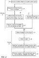
- Fig. 2 is a flow chart that schematically illustrates a method for operating an AVL location-measuring system.
- the process may begin with a calibration phase 71, after which the system is operated in an investigative tracking phase 72.
- the two phases may run at least partially in parallel while preforming a catheterization session.
- Calibration phase 71 may begin with processor 46 directing, at an acquisition step 74, the measurement of both calibration-voltages and magnetically induced position signals with calibration-catheter 30.
- the calibration-voltages are induced between AVL patches 60P and measured by electrode 32.
- the position signals are induced in magnetic sensor 37 in response to magnetic fields driven by generators 35.
- processor 46 uses the position signals received from magnetic sensor 37, and the five calibration-voltages received from electrode 32, to generate a VPM matrix for each measured location in the region, at a VPM calculation step 76.
- processor 46 evaluates the cost-function that will later be used to examine sub-sets of three AVL patches, per each location, in the given region, at a cost-function construction step 78.
- processor 46 identifies and selects the optimized sub-set of three AVL patches over the given region, at an AVL patch identification step 80.
- Processor 46 further records the selected AVL patch identities in memory for future use, at a storing step 82. The identity of a fourth AVL patch, serving as a common ground, is stored as well.
- processor 46 directs the application of modulated voltages by all five AVL patches, and receives investigation-voltages from an investigation-electrode of an AVL catheter, at an acquisition step 84. Based on the investigation-voltages and the VPM matrix, processor 46 calculates a region where the investigation-tool is located, at a region determination step 86.
- processor 46 selects (e.g., retrieves from memory the selection of) the three investigation-voltages that were measured using the three AVL patches stored at step 82.
- the AVL system directs the AVL patches belonging to the selected sub-set to generate modulated voltages, and the investigation-electrode to measure the investigation-voltages, at a location measurement step 88.
- all AVL patches generate their respective voltages.
- Processor 46 uses only the three investigation-voltages generated by the AVL patches belonging to the selected sub-set, and ignores the others.
- processor 46 calculates an exact location of the investigation-tool, at a location determining step 90.
- the process may loop back to step 74 in order to receive position signals, for example from a new region of heart 38, until mapping is completed.
- Fig. 2 The example flow chart shown in Fig. 2 is chosen purely for the sake of conceptual clarity. In alternative embodiments, additional steps may be performed, such as calibration steps and/or adjustment steps.
- the selection process of an optimized sub-set of AVL patches may be different, and, for example, steps 78 and 80 may run partially in parallel to shorten computation time.
Landscapes
- Health & Medical Sciences (AREA)
- Life Sciences & Earth Sciences (AREA)
- Engineering & Computer Science (AREA)
- Physics & Mathematics (AREA)
- Animal Behavior & Ethology (AREA)
- Veterinary Medicine (AREA)
- Public Health (AREA)
- Biomedical Technology (AREA)
- Heart & Thoracic Surgery (AREA)
- General Health & Medical Sciences (AREA)
- Pathology (AREA)
- Molecular Biology (AREA)
- Medical Informatics (AREA)
- Biophysics (AREA)
- Surgery (AREA)
- Radiology & Medical Imaging (AREA)
- Nuclear Medicine, Radiotherapy & Molecular Imaging (AREA)
- Human Computer Interaction (AREA)
- Cardiology (AREA)
- General Physics & Mathematics (AREA)
- Neurology (AREA)
- Condensed Matter Physics & Semiconductors (AREA)
- Measurement And Recording Of Electrical Phenomena And Electrical Characteristics Of The Living Body (AREA)
- Surgical Instruments (AREA)
Claims (6)
- Système (36), comprenant :de multiples électrodes de surface (60P), qui sont fixées de manière externe au patient (40) et qui sont configurées pour transmettre de multiples tensions respectives dans un cœur (38) du patient ;un processeur (46), qui est configuré pour :répéter pour chaque région d'une pluralité de régions du cœur :(i) la réception (74) de multiples tensions d'étalonnage mesurées dans la région par une électrode (32) portée par un outil d'étalonnage (30) ;(ii) la sélection (80) pour la région d'un sous-ensemble partiel respectif des électrodes de surface dont les tensions d'étalonnage correspondantes minimisent une fonction de coût, la fonction de coût comprenant un premier terme qui dépend de l'amplitude de gradients des tensions d'étalonnage mesurées, et un second terme qui dépend de corrélations entre les gradients ; et(iii) l'enregistrement (82) du sous-ensemble partiel d'électrodes de surface, sélectionnées pour la région, pour une utilisation lors d'une session suivante ; et recevoir de multiples mesures de localisation provenant d'un système de mesure de localisation qui suit l'outil d'étalonnage au niveau de multiples localisations du cœur, et dériver les relations respectives entre les multiples mesures de localisation et les ensembles respectifs de tensions d'étalonnage mesurées ; etdans la session suivante, calculer une position d'une sonde insérée dans une région donnée du cœur, par :réception (84) de multiples tensions d'investigation mesurées à l'aide de la sonde ;dérivation (86) d'une identité de la région donnée à partir des tensions d'investigation mesurées et des relations dérivées ; etcalcul (90) de la position de la sonde, sur la base uniquement des tensions d'investigation mesurées qui proviennent des électrodes de surface appartenant au sous-ensemble sélectionné pour la région donnée.
- Système selon la revendication 1, le système de mesure de localisation comprenant un système de localisation magnétique.
- Système selon la revendication 1, le système de mesure de localisation comprenant un système d'imagerie médicale.
- Système selon la revendication 1, le processeur étant configuré pour calculer la position de la sonde sur la base du sous-ensemble sélectionné de tensions d'investigation mesurées et sur la base d'un sous-ensemble respectif des relations dérivées.
- Système selon la revendication 1, le système étant configuré pour transmettre les multiples tensions par sélection d'une électrode de surface pour servir de masse commune, et par application des tensions entre une ou plusieurs électrodes de surface restantes et la masse commune.
- Système selon la revendication 1, le système étant configuré pour mesurer les tensions d'investigation à l'aide d'une ou plusieurs électrodes d'investigation montées au niveau d'une extrémité distale de la sonde.
Applications Claiming Priority (1)
| Application Number | Priority Date | Filing Date | Title |
|---|---|---|---|
| US15/966,514 US10722141B2 (en) | 2018-04-30 | 2018-04-30 | Active voltage location (AVL) resolution |
Publications (2)
| Publication Number | Publication Date |
|---|---|
| EP3563763A1 EP3563763A1 (fr) | 2019-11-06 |
| EP3563763B1 true EP3563763B1 (fr) | 2021-02-24 |
Family
ID=66323730
Family Applications (1)
| Application Number | Title | Priority Date | Filing Date |
|---|---|---|---|
| EP19171540.8A Active EP3563763B1 (fr) | 2018-04-30 | 2019-04-29 | Résolution améliorée de localisation de tension active (avl) |
Country Status (7)
| Country | Link |
|---|---|
| US (1) | US10722141B2 (fr) |
| EP (1) | EP3563763B1 (fr) |
| JP (1) | JP7305419B2 (fr) |
| CN (1) | CN110403605B (fr) |
| AU (1) | AU2019201809A1 (fr) |
| CA (1) | CA3038310A1 (fr) |
| IL (1) | IL265345B (fr) |
Families Citing this family (6)
| Publication number | Priority date | Publication date | Assignee | Title |
|---|---|---|---|---|
| US11660050B2 (en) | 2018-10-25 | 2023-05-30 | Biosense Webster (Israel) Ltd | Balloon catheter with diagnostic electrodes, far field electrodes, and guidewire |
| US11903639B2 (en) | 2020-04-17 | 2024-02-20 | Biosense Webster (Israel) Ltd. | Flexible distal-end assembly with double-sided electrode array and irrigation |
| US12285206B2 (en) | 2020-06-01 | 2025-04-29 | Biosense Webster (Israel) Ltd. | Application of irreversible electroporation (IRE) ablation using catheter with electrode array |
| US11918281B2 (en) | 2020-10-07 | 2024-03-05 | Biosense Webster (Israel) Ltd. | Folding fan catheter with electrodes |
| US12059535B2 (en) * | 2021-01-28 | 2024-08-13 | Biosense Webster (Israel) Ltd. | Managing medical device equipment by online magnetic calibration of a catheter |
| CN115721291B (zh) * | 2021-08-31 | 2024-12-17 | 上海微创电生理医疗科技股份有限公司 | 定位系统、方法、介入手术系统、电子设备和存储介质 |
Family Cites Families (23)
| Publication number | Priority date | Publication date | Assignee | Title |
|---|---|---|---|---|
| US5391199A (en) | 1993-07-20 | 1995-02-21 | Biosense, Inc. | Apparatus and method for treating cardiac arrhythmias |
| JP3708121B2 (ja) | 1994-08-19 | 2005-10-19 | バイオセンス・インコーポレイテッド | 医療用機器の診断及び取扱いならびに映像システム |
| US6690963B2 (en) | 1995-01-24 | 2004-02-10 | Biosense, Inc. | System for determining the location and orientation of an invasive medical instrument |
| US5697377A (en) | 1995-11-22 | 1997-12-16 | Medtronic, Inc. | Catheter mapping system and method |
| IL125761A (en) | 1996-02-15 | 2005-05-17 | Biosense Inc | Independently positionable transducers for location system |
| IL125757A (en) | 1996-02-15 | 2003-09-17 | Biosense Inc | Medical procedures and apparatus using intrabody probes |
| US6050267A (en) | 1997-04-28 | 2000-04-18 | American Cardiac Ablation Co. Inc. | Catheter positioning system |
| US6239724B1 (en) | 1997-12-30 | 2001-05-29 | Remon Medical Technologies, Ltd. | System and method for telemetrically providing intrabody spatial position |
| US6484118B1 (en) | 2000-07-20 | 2002-11-19 | Biosense, Inc. | Electromagnetic position single axis system |
| US7729742B2 (en) | 2001-12-21 | 2010-06-01 | Biosense, Inc. | Wireless position sensor |
| US20040068178A1 (en) | 2002-09-17 | 2004-04-08 | Assaf Govari | High-gradient recursive locating system |
| US7869865B2 (en) | 2005-01-07 | 2011-01-11 | Biosense Webster, Inc. | Current-based position sensing |
| US7848787B2 (en) | 2005-07-08 | 2010-12-07 | Biosense Webster, Inc. | Relative impedance measurement |
| US7536218B2 (en) * | 2005-07-15 | 2009-05-19 | Biosense Webster, Inc. | Hybrid magnetic-based and impedance-based position sensing |
| US7756576B2 (en) | 2005-08-26 | 2010-07-13 | Biosense Webster, Inc. | Position sensing and detection of skin impedance |
| US9737225B2 (en) | 2008-06-24 | 2017-08-22 | Biosense Webster, Inc. | Patch and sensor assembly for use in medical device localization and mapping systems |
| US8456182B2 (en) | 2008-09-30 | 2013-06-04 | Biosense Webster, Inc. | Current localization tracker |
| US8694074B2 (en) * | 2010-05-11 | 2014-04-08 | Rhythmia Medical, Inc. | Electrode displacement determination |
| US8478383B2 (en) * | 2010-12-14 | 2013-07-02 | Biosense Webster (Israel), Ltd. | Probe tracking using multiple tracking methods |
| US9002442B2 (en) * | 2011-01-13 | 2015-04-07 | Rhythmia Medical, Inc. | Beat alignment and selection for cardiac mapping |
| US9510772B2 (en) | 2012-04-10 | 2016-12-06 | Cardionxt, Inc. | System and method for localizing medical instruments during cardiovascular medical procedures |
| CN107148552B (zh) | 2014-09-26 | 2020-09-18 | 科迪影技术股份有限公司 | 导电体积内的物体的定位 |
| US11033201B2 (en) * | 2015-09-04 | 2021-06-15 | Biosense Webster (Israel) Ltd. | Inconsistent field-based patch location coordinate correction |
-
2018
- 2018-04-30 US US15/966,514 patent/US10722141B2/en active Active
-
2019
- 2019-03-13 IL IL265345A patent/IL265345B/en unknown
- 2019-03-15 AU AU2019201809A patent/AU2019201809A1/en not_active Abandoned
- 2019-03-28 CA CA3038310A patent/CA3038310A1/fr not_active Abandoned
- 2019-04-26 JP JP2019085186A patent/JP7305419B2/ja active Active
- 2019-04-29 EP EP19171540.8A patent/EP3563763B1/fr active Active
- 2019-04-30 CN CN201910359987.9A patent/CN110403605B/zh active Active
Also Published As
| Publication number | Publication date |
|---|---|
| EP3563763A1 (fr) | 2019-11-06 |
| CN110403605B (zh) | 2024-04-02 |
| JP2019193789A (ja) | 2019-11-07 |
| JP7305419B2 (ja) | 2023-07-10 |
| CA3038310A1 (fr) | 2019-10-30 |
| US20190328274A1 (en) | 2019-10-31 |
| AU2019201809A1 (en) | 2019-11-14 |
| US10722141B2 (en) | 2020-07-28 |
| IL265345B (en) | 2022-02-01 |
| CN110403605A (zh) | 2019-11-05 |
| IL265345A (en) | 2019-05-30 |
Similar Documents
| Publication | Publication Date | Title |
|---|---|---|
| EP3643223B1 (fr) | Système combinant localisation par courant actif (acl) et d'indication de proximité des tissus (tpi) | |
| US10722141B2 (en) | Active voltage location (AVL) resolution | |
| US9023027B2 (en) | Current localization tracker | |
| EP2168478B1 (fr) | Dispositif pour la détermination de la position d'un appareil d'observation à l'aide d'une compensation du drainage du courant involontaire | |
| EP1626660B1 (fr) | Systemes d'enregistrement d'une image echographique dans un systeme de coordonnees tridimensionnel | |
| JP6301051B2 (ja) | 複数の追跡方法を用いたプローブ追跡 | |
| JP2016105803A (ja) | インピーダンスおよび磁界の測定を使用するカテーテルのナビゲーション | |
| EP3505061B1 (fr) | Amélioration de la performance de suivi de position par impédance à l'aide de l'analyse en composantes principales | |
| EP3583895B1 (fr) | Identification d'ensembles orthogonaux de patchs de position actuelle active (acl) | |
| EP4129168B1 (fr) | Système et procédé de localisation automatique de la position spatiale d'électrodes sur un corps de conducteur | |
| JP7247055B2 (ja) | 能動電流位置(acl)における静電容量効果の低減 | |
| JP2021094388A (ja) | 二重電位問題の解決方法 |
Legal Events
| Date | Code | Title | Description |
|---|---|---|---|
| PUAI | Public reference made under article 153(3) epc to a published international application that has entered the european phase |
Free format text: ORIGINAL CODE: 0009012 |
|
| STAA | Information on the status of an ep patent application or granted ep patent |
Free format text: STATUS: THE APPLICATION HAS BEEN PUBLISHED |
|
| AK | Designated contracting states |
Kind code of ref document: A1 Designated state(s): AL AT BE BG CH CY CZ DE DK EE ES FI FR GB GR HR HU IE IS IT LI LT LU LV MC MK MT NL NO PL PT RO RS SE SI SK SM TR |
|
| AX | Request for extension of the european patent |
Extension state: BA ME |
|
| STAA | Information on the status of an ep patent application or granted ep patent |
Free format text: STATUS: REQUEST FOR EXAMINATION WAS MADE |
|
| 17P | Request for examination filed |
Effective date: 20200323 |
|
| RBV | Designated contracting states (corrected) |
Designated state(s): AL AT BE BG CH CY CZ DE DK EE ES FI FR GB GR HR HU IE IS IT LI LT LU LV MC MK MT NL NO PL PT RO RS SE SI SK SM TR |
|
| RIC1 | Information provided on ipc code assigned before grant |
Ipc: A61B 5/06 20060101AFI20200831BHEP |
|
| GRAP | Despatch of communication of intention to grant a patent |
Free format text: ORIGINAL CODE: EPIDOSNIGR1 |
|
| STAA | Information on the status of an ep patent application or granted ep patent |
Free format text: STATUS: GRANT OF PATENT IS INTENDED |
|
| INTG | Intention to grant announced |
Effective date: 20201019 |
|
| GRAS | Grant fee paid |
Free format text: ORIGINAL CODE: EPIDOSNIGR3 |
|
| GRAA | (expected) grant |
Free format text: ORIGINAL CODE: 0009210 |
|
| STAA | Information on the status of an ep patent application or granted ep patent |
Free format text: STATUS: THE PATENT HAS BEEN GRANTED |
|
| AK | Designated contracting states |
Kind code of ref document: B1 Designated state(s): AL AT BE BG CH CY CZ DE DK EE ES FI FR GB GR HR HU IE IS IT LI LT LU LV MC MK MT NL NO PL PT RO RS SE SI SK SM TR |
|
| REG | Reference to a national code |
Ref country code: CH Ref legal event code: EP |
|
| REG | Reference to a national code |
Ref country code: DE Ref legal event code: R096 Ref document number: 602019002698 Country of ref document: DE |
|
| REG | Reference to a national code |
Ref country code: AT Ref legal event code: REF Ref document number: 1363471 Country of ref document: AT Kind code of ref document: T Effective date: 20210315 |
|
| REG | Reference to a national code |
Ref country code: IE Ref legal event code: FG4D |
|
| REG | Reference to a national code |
Ref country code: NL Ref legal event code: FP |
|
| REG | Reference to a national code |
Ref country code: LT Ref legal event code: MG9D |
|
| PG25 | Lapsed in a contracting state [announced via postgrant information from national office to epo] |
Ref country code: BG Free format text: LAPSE BECAUSE OF FAILURE TO SUBMIT A TRANSLATION OF THE DESCRIPTION OR TO PAY THE FEE WITHIN THE PRESCRIBED TIME-LIMIT Effective date: 20210524 Ref country code: HR Free format text: LAPSE BECAUSE OF FAILURE TO SUBMIT A TRANSLATION OF THE DESCRIPTION OR TO PAY THE FEE WITHIN THE PRESCRIBED TIME-LIMIT Effective date: 20210224 Ref country code: FI Free format text: LAPSE BECAUSE OF FAILURE TO SUBMIT A TRANSLATION OF THE DESCRIPTION OR TO PAY THE FEE WITHIN THE PRESCRIBED TIME-LIMIT Effective date: 20210224 Ref country code: GR Free format text: LAPSE BECAUSE OF FAILURE TO SUBMIT A TRANSLATION OF THE DESCRIPTION OR TO PAY THE FEE WITHIN THE PRESCRIBED TIME-LIMIT Effective date: 20210525 Ref country code: NO Free format text: LAPSE BECAUSE OF FAILURE TO SUBMIT A TRANSLATION OF THE DESCRIPTION OR TO PAY THE FEE WITHIN THE PRESCRIBED TIME-LIMIT Effective date: 20210524 Ref country code: PT Free format text: LAPSE BECAUSE OF FAILURE TO SUBMIT A TRANSLATION OF THE DESCRIPTION OR TO PAY THE FEE WITHIN THE PRESCRIBED TIME-LIMIT Effective date: 20210624 Ref country code: LT Free format text: LAPSE BECAUSE OF FAILURE TO SUBMIT A TRANSLATION OF THE DESCRIPTION OR TO PAY THE FEE WITHIN THE PRESCRIBED TIME-LIMIT Effective date: 20210224 |
|
| REG | Reference to a national code |
Ref country code: AT Ref legal event code: MK05 Ref document number: 1363471 Country of ref document: AT Kind code of ref document: T Effective date: 20210224 |
|
| PG25 | Lapsed in a contracting state [announced via postgrant information from national office to epo] |
Ref country code: PL Free format text: LAPSE BECAUSE OF FAILURE TO SUBMIT A TRANSLATION OF THE DESCRIPTION OR TO PAY THE FEE WITHIN THE PRESCRIBED TIME-LIMIT Effective date: 20210224 Ref country code: RS Free format text: LAPSE BECAUSE OF FAILURE TO SUBMIT A TRANSLATION OF THE DESCRIPTION OR TO PAY THE FEE WITHIN THE PRESCRIBED TIME-LIMIT Effective date: 20210224 Ref country code: LV Free format text: LAPSE BECAUSE OF FAILURE TO SUBMIT A TRANSLATION OF THE DESCRIPTION OR TO PAY THE FEE WITHIN THE PRESCRIBED TIME-LIMIT Effective date: 20210224 Ref country code: SE Free format text: LAPSE BECAUSE OF FAILURE TO SUBMIT A TRANSLATION OF THE DESCRIPTION OR TO PAY THE FEE WITHIN THE PRESCRIBED TIME-LIMIT Effective date: 20210224 |
|
| PG25 | Lapsed in a contracting state [announced via postgrant information from national office to epo] |
Ref country code: IS Free format text: LAPSE BECAUSE OF FAILURE TO SUBMIT A TRANSLATION OF THE DESCRIPTION OR TO PAY THE FEE WITHIN THE PRESCRIBED TIME-LIMIT Effective date: 20210624 |
|
| PG25 | Lapsed in a contracting state [announced via postgrant information from national office to epo] |
Ref country code: SM Free format text: LAPSE BECAUSE OF FAILURE TO SUBMIT A TRANSLATION OF THE DESCRIPTION OR TO PAY THE FEE WITHIN THE PRESCRIBED TIME-LIMIT Effective date: 20210224 Ref country code: AT Free format text: LAPSE BECAUSE OF FAILURE TO SUBMIT A TRANSLATION OF THE DESCRIPTION OR TO PAY THE FEE WITHIN THE PRESCRIBED TIME-LIMIT Effective date: 20210224 Ref country code: EE Free format text: LAPSE BECAUSE OF FAILURE TO SUBMIT A TRANSLATION OF THE DESCRIPTION OR TO PAY THE FEE WITHIN THE PRESCRIBED TIME-LIMIT Effective date: 20210224 Ref country code: CZ Free format text: LAPSE BECAUSE OF FAILURE TO SUBMIT A TRANSLATION OF THE DESCRIPTION OR TO PAY THE FEE WITHIN THE PRESCRIBED TIME-LIMIT Effective date: 20210224 |
|
| REG | Reference to a national code |
Ref country code: DE Ref legal event code: R097 Ref document number: 602019002698 Country of ref document: DE |
|
| PG25 | Lapsed in a contracting state [announced via postgrant information from national office to epo] |
Ref country code: MC Free format text: LAPSE BECAUSE OF FAILURE TO SUBMIT A TRANSLATION OF THE DESCRIPTION OR TO PAY THE FEE WITHIN THE PRESCRIBED TIME-LIMIT Effective date: 20210224 Ref country code: SK Free format text: LAPSE BECAUSE OF FAILURE TO SUBMIT A TRANSLATION OF THE DESCRIPTION OR TO PAY THE FEE WITHIN THE PRESCRIBED TIME-LIMIT Effective date: 20210224 Ref country code: RO Free format text: LAPSE BECAUSE OF FAILURE TO SUBMIT A TRANSLATION OF THE DESCRIPTION OR TO PAY THE FEE WITHIN THE PRESCRIBED TIME-LIMIT Effective date: 20210224 Ref country code: DK Free format text: LAPSE BECAUSE OF FAILURE TO SUBMIT A TRANSLATION OF THE DESCRIPTION OR TO PAY THE FEE WITHIN THE PRESCRIBED TIME-LIMIT Effective date: 20210224 |
|
| PG25 | Lapsed in a contracting state [announced via postgrant information from national office to epo] |
Ref country code: LU Free format text: LAPSE BECAUSE OF NON-PAYMENT OF DUE FEES Effective date: 20210429 |
|
| PLBE | No opposition filed within time limit |
Free format text: ORIGINAL CODE: 0009261 |
|
| STAA | Information on the status of an ep patent application or granted ep patent |
Free format text: STATUS: NO OPPOSITION FILED WITHIN TIME LIMIT |
|
| REG | Reference to a national code |
Ref country code: BE Ref legal event code: MM Effective date: 20210430 |
|
| PG25 | Lapsed in a contracting state [announced via postgrant information from national office to epo] |
Ref country code: AL Free format text: LAPSE BECAUSE OF FAILURE TO SUBMIT A TRANSLATION OF THE DESCRIPTION OR TO PAY THE FEE WITHIN THE PRESCRIBED TIME-LIMIT Effective date: 20210224 Ref country code: ES Free format text: LAPSE BECAUSE OF FAILURE TO SUBMIT A TRANSLATION OF THE DESCRIPTION OR TO PAY THE FEE WITHIN THE PRESCRIBED TIME-LIMIT Effective date: 20210224 |
|
| 26N | No opposition filed |
Effective date: 20211125 |
|
| PG25 | Lapsed in a contracting state [announced via postgrant information from national office to epo] |
Ref country code: SI Free format text: LAPSE BECAUSE OF FAILURE TO SUBMIT A TRANSLATION OF THE DESCRIPTION OR TO PAY THE FEE WITHIN THE PRESCRIBED TIME-LIMIT Effective date: 20210224 |
|
| PG25 | Lapsed in a contracting state [announced via postgrant information from national office to epo] |
Ref country code: IE Free format text: LAPSE BECAUSE OF NON-PAYMENT OF DUE FEES Effective date: 20210429 |
|
| PG25 | Lapsed in a contracting state [announced via postgrant information from national office to epo] |
Ref country code: IS Free format text: LAPSE BECAUSE OF FAILURE TO SUBMIT A TRANSLATION OF THE DESCRIPTION OR TO PAY THE FEE WITHIN THE PRESCRIBED TIME-LIMIT Effective date: 20210624 |
|
| PGFP | Annual fee paid to national office [announced via postgrant information from national office to epo] |
Ref country code: NL Payment date: 20220314 Year of fee payment: 4 |
|
| PG25 | Lapsed in a contracting state [announced via postgrant information from national office to epo] |
Ref country code: BE Free format text: LAPSE BECAUSE OF NON-PAYMENT OF DUE FEES Effective date: 20210430 |
|
| REG | Reference to a national code |
Ref country code: CH Ref legal event code: PL |
|
| PG25 | Lapsed in a contracting state [announced via postgrant information from national office to epo] |
Ref country code: LI Free format text: LAPSE BECAUSE OF NON-PAYMENT OF DUE FEES Effective date: 20220430 Ref country code: CH Free format text: LAPSE BECAUSE OF NON-PAYMENT OF DUE FEES Effective date: 20220430 |
|
| PG25 | Lapsed in a contracting state [announced via postgrant information from national office to epo] |
Ref country code: CY Free format text: LAPSE BECAUSE OF FAILURE TO SUBMIT A TRANSLATION OF THE DESCRIPTION OR TO PAY THE FEE WITHIN THE PRESCRIBED TIME-LIMIT Effective date: 20210224 |
|
| PG25 | Lapsed in a contracting state [announced via postgrant information from national office to epo] |
Ref country code: HU Free format text: LAPSE BECAUSE OF FAILURE TO SUBMIT A TRANSLATION OF THE DESCRIPTION OR TO PAY THE FEE WITHIN THE PRESCRIBED TIME-LIMIT; INVALID AB INITIO Effective date: 20190429 |
|
| REG | Reference to a national code |
Ref country code: NL Ref legal event code: MM Effective date: 20230501 |
|
| PG25 | Lapsed in a contracting state [announced via postgrant information from national office to epo] |
Ref country code: NL Free format text: LAPSE BECAUSE OF NON-PAYMENT OF DUE FEES Effective date: 20230501 |
|
| PG25 | Lapsed in a contracting state [announced via postgrant information from national office to epo] |
Ref country code: MK Free format text: LAPSE BECAUSE OF FAILURE TO SUBMIT A TRANSLATION OF THE DESCRIPTION OR TO PAY THE FEE WITHIN THE PRESCRIBED TIME-LIMIT Effective date: 20210224 |
|
| PG25 | Lapsed in a contracting state [announced via postgrant information from national office to epo] |
Ref country code: MT Free format text: LAPSE BECAUSE OF FAILURE TO SUBMIT A TRANSLATION OF THE DESCRIPTION OR TO PAY THE FEE WITHIN THE PRESCRIBED TIME-LIMIT Effective date: 20210224 |
|
| PGFP | Annual fee paid to national office [announced via postgrant information from national office to epo] |
Ref country code: GB Payment date: 20250306 Year of fee payment: 7 |
|
| PGFP | Annual fee paid to national office [announced via postgrant information from national office to epo] |
Ref country code: DE Payment date: 20250305 Year of fee payment: 7 |
|
| PG25 | Lapsed in a contracting state [announced via postgrant information from national office to epo] |
Ref country code: TR Free format text: LAPSE BECAUSE OF FAILURE TO SUBMIT A TRANSLATION OF THE DESCRIPTION OR TO PAY THE FEE WITHIN THE PRESCRIBED TIME-LIMIT Effective date: 20210224 |
|
| PGFP | Annual fee paid to national office [announced via postgrant information from national office to epo] |
Ref country code: IT Payment date: 20260320 Year of fee payment: 8 |
|
| PGFP | Annual fee paid to national office [announced via postgrant information from national office to epo] |
Ref country code: FR Payment date: 20260309 Year of fee payment: 8 |