EP3563992A1 - Dispositif et procédé de diagnostic de défaut pour réducteurs de vitesse et dispositif mécanique comprenant ledit dispositif de diagnostic de défaut - Google Patents
Dispositif et procédé de diagnostic de défaut pour réducteurs de vitesse et dispositif mécanique comprenant ledit dispositif de diagnostic de défaut Download PDFInfo
- Publication number
- EP3563992A1 EP3563992A1 EP17885804.9A EP17885804A EP3563992A1 EP 3563992 A1 EP3563992 A1 EP 3563992A1 EP 17885804 A EP17885804 A EP 17885804A EP 3563992 A1 EP3563992 A1 EP 3563992A1
- Authority
- EP
- European Patent Office
- Prior art keywords
- motor
- reduction gear
- motor current
- rotation speed
- acceleration
- Prior art date
- Legal status (The legal status is an assumption and is not a legal conclusion. Google has not performed a legal analysis and makes no representation as to the accuracy of the status listed.)
- Granted
Links
Images





Classifications
-
- G—PHYSICS
- G01—MEASURING; TESTING
- G01M—TESTING STATIC OR DYNAMIC BALANCE OF MACHINES OR STRUCTURES; TESTING OF STRUCTURES OR APPARATUS, NOT OTHERWISE PROVIDED FOR
- G01M13/00—Testing of machine parts
- G01M13/02—Gearings; Transmission mechanisms
- G01M13/021—Gearings
-
- B—PERFORMING OPERATIONS; TRANSPORTING
- B25—HAND TOOLS; PORTABLE POWER-DRIVEN TOOLS; MANIPULATORS
- B25J—MANIPULATORS; CHAMBERS PROVIDED WITH MANIPULATION DEVICES
- B25J19/00—Accessories fitted to manipulators, e.g. for monitoring, for viewing; Safety devices combined with or specially adapted for use in connection with manipulators
- B25J19/0095—Means or methods for testing manipulators
-
- B—PERFORMING OPERATIONS; TRANSPORTING
- B25—HAND TOOLS; PORTABLE POWER-DRIVEN TOOLS; MANIPULATORS
- B25J—MANIPULATORS; CHAMBERS PROVIDED WITH MANIPULATION DEVICES
- B25J19/00—Accessories fitted to manipulators, e.g. for monitoring, for viewing; Safety devices combined with or specially adapted for use in connection with manipulators
- B25J19/06—Safety devices
-
- G—PHYSICS
- G01—MEASURING; TESTING
- G01M—TESTING STATIC OR DYNAMIC BALANCE OF MACHINES OR STRUCTURES; TESTING OF STRUCTURES OR APPARATUS, NOT OTHERWISE PROVIDED FOR
- G01M13/00—Testing of machine parts
- G01M13/02—Gearings; Transmission mechanisms
Definitions
- the present disclosure relates to a failure diagnosis device for a reduction gear, a method of diagnosing failure, and a mechanical apparatus provided with the failure diagnosis device.
- a diagnosis device for such an abnormality of the reduction gear it is known that, for example, a device which estimates a disturbance estimated value of the reduction gear based on a torque command and a speed feedback, and then diagnoses the abnormality of the reduction gear based on an amplitude of a specific spectrum extracted from a frequency component of the disturbance estimated value (for example, refer to Patent Document 1).
- the abnormality diagnosis device requires for a driven member, which is rotated by a motor, to be rotated at a constant speed.
- the constant speed period does not always exist, while a robot operates variously.
- the abnormal diagnostic method for example, before the robot starts a work, it is necessary to carry out the abnormality diagnosis, while causing the robot to perform a given operation which includes the constant speed period.
- the conventional abnormality (failure) diagnosis device has a problem that the abnormality (failure) diagnosis cannot be performed during the work of the robot. Moreover, this is a common problem to entire mechanical apparatuses provided with a reduction gear, including robots.
- the present disclosure is made in view of solving such a problem, and one purpose thereof is to provide a failure diagnosis device for a reduction gear, a method of diagnosing failure, and a mechanical apparatus provided with the failure diagnosis device, capable of performing a failure diagnosis during a work of the mechanical apparatus provided with the reduction gear.
- a failure diagnosis device for a reduction gear is a failure diagnosis device for a reduction gear provided to a mechanical apparatus driven by a motor so that the reduction gear slows down rotation power of the motor and transmits the power to an operating part of the mechanical apparatus.
- the device identifies an acceleration/deceleration period during which operation of the mechanical apparatus accelerates and/or decelerates, and determines whether the reduction gear indicates a sign of failure based on a change in frequency spectrum of one of load current of the motor and a current value having a correlation with the load current (hereinafter, referred to as "the motor current") with respect to a change in a rotation speed of the motor during the acceleration/deceleration period.
- slow down rotation power of the motor includes both of slowing down the rotation power inputted from the motor directly to the reduction gear, and slowing down the rotation power inputted from the motor indirectly to the reduction gear.
- transmits the power to the operating part of the mechanical apparatus includes both of transmitting directly to the operating part of the mechanical apparatus, and transmitting indirectly to the operating part of the mechanical apparatus.
- rotation speed of the motor includes both of an actual rotation speed of the motor, and a physical amount having a correlation with the actual rotation speed (e.g., a rotation speed of an output shaft of the reduction gear, a rotation speed of a rotation shaft of the operating part of the mechanical apparatus driven by the motor, etc.).
- the acceleration/deceleration period during which the operation of the mechanical apparatus accelerates and/or decelerates can be identified.
- the current amplitude within a particular frequency range corresponding to the specific frequency of the reduction gear increases by resonance of the reduction gear, and presents the peak value.
- This peak value has the correlation with the sign of failure of the reduction gear. Therefore, it can be determined whether the reduction gear indicates the sign of failure based on the change in the frequency spectrum of the motor current data with respect to the change in the rotation speed of the motor. Therefore, the failure diagnosis can be performed during the work of the mechanical apparatus provided with the reduction gear.
- the failure diagnosis device may include a rotation speed acquiring module configured to acquire the rotation speed of the motor, an acceleration/deceleration period identifying module configured to identify the acceleration/deceleration period based on the rotation speed of the motor acquired by the rotation speed acquiring module, a motor current acquiring module configured to acquire the motor current, a time series rotation speed data generating module configured to sequentially sample the rotation speed of the motor acquired by the rotation speed acquiring module during the acceleration/deceleration period, and generate a group of time series rotation speed data, a time series motor current data generating module configured to sequentially sample the motor current acquired by the motor current acquiring module during the acceleration/deceleration period, and generate a group of time series motor current data, a FFT analyzing module configured to make the group of time series motor current data correspond to the group of time series rotation speed data, conduct a frequency analysis of the group of time series motor current data, and generate the frequency spectra of the group of motor current data corresponding to the group of time series rotation speed data, an amplitude peak value extracting
- the failure diagnosis device capable of performing the failure diagnosis during the work of the mechanical apparatus provided with the reduction gear, is suitably implemented.
- the amplitude threshold may be an allowable amplitude threshold corresponding to an allowable abrasion amount threshold indicative of an acceptable limit of an amount of abrasion of the reduction gear.
- the sign of failure of the reduction gear can be determined accurately.
- the determination may be performed when the motor current is above a given value.
- the reduction gear may be configured so that an output shaft thereof only rotates within a rotation range less than one revolution in an operating range of the mechanical apparatus.
- the failure diagnosis can be performed during the work of the mechanical apparatus provided with the reduction gear.
- the acceleration/deceleration period may be an acceleration period.
- the existence of the sign of failure is determined during the acceleration period of the operation of the mechanical apparatus.
- the peak value of the current amplitude within the particular frequency range by the resonance of the reduction gear appears more clearly. Therefore, the existence of the sign of failure can be determined more accurately.
- the acceleration/deceleration period may be a deceleration period.
- a mechanical apparatus includes any one of the failure diagnosis devices described above.
- the failure determination can be performed during the work of the mechanical apparatus.
- a method of diagnosing failure of a reduction gear is a method of diagnosing failure of a reduction gear provided to a mechanical apparatus driven by a motor so that the reduction gear slows down the rotation power of the motor and transmits the power to an operating part of the mechanical apparatus.
- the method includes the steps of (a) identifying an acceleration/deceleration period during which operation of the mechanical apparatus accelerates and/or decelerates, and (b) determining whether the reduction gear indicates a sign of failure based on a change in frequency spectrum of one of load current of the motor and a current value having a correlation with the load current (hereinafter, referred to as "the motor current") with respect to a change in a rotation speed of the motor during the acceleration/deceleration period.
- the failure determination can be performed during the work of the mechanical apparatus provided with the reduction gear.
- the present disclosure has effects of providing the failure diagnosis device for the reduction gear, the method of diagnosing the failure, and the mechanical apparatus provided with the failure diagnosis device, capable of performing the failure diagnosis during the work of the mechanical apparatus provided with the reduction gear.
- the present inventors examined diligently in order to enable a failure diagnosis to be performed during a work of a mechanical apparatus provided with a reduction gear.
- the present inventors set a first premise to find out a failure diagnosis specialized for the reduction gear. Moreover, for example, an output shaft of a reduction gear for an industrial robot only rotates within a rotation range less than one revolution, in an operating range of the robot. Thus, the present inventors set a second premise to find out a failure diagnosis which is also effective for such a reduction gear. Further, for example, since the industrial robot is driven by a motor, and operation of the robot is controlled by controlling motor current, a sensor which detects basic data for the analysis can be omitted, if the motor current can be used as the basic data for analyzing the failure. Thus, the present inventors set a third premise to use the motor current as the basic data for analyzing the failure.
- motor current is a concept on the control and includes load current of the motor, and a current value having a correlation with the load current (for example, a current instruction value outputted from a controller to a drive circuit (power converter) for the motor).
- the present inventors found out in the industrial robot having the reduction gear in which the output shaft only rotates within the rotation range less than one revolution in the operating range of the robot, that in a change of frequency spectrum of the motor current with respect to a change in a rotation speed of the motor (refer to Fig. 2 ), current amplitude within a particular frequency range corresponding to the specific frequency of the reduction gear increases by the resonance of the reduction gear, and indicates a well-defined peak value (refer to Figs. 4A to 4E ).
- the present inventors examined by an experiment a change in the amplitude of the motor current within the particular frequency range corresponding to the specific frequency of the reduction gear with respect to a change in concentration of iron powder in grease (hereinafter, referred to as the "iron powder concentration of grease”) for the reduction gear (refer to Figs. 4A to 4E ).
- the iron powder concentration of the grease for the reduction gear has a relation with degradation (a sign of failure) of the reduction gear.
- the present inventors found out that there is a correlation between the iron powder concentration of the grease for the reduction gear, and the peak value of the amplitude of the motor current within the particular frequency range corresponding to the specific frequency of the reduction gear (refer to Fig. 5 ).
- the present inventors found out that the peak value of the amplitude of the motor current within the particular frequency range has a correlation with the sign of failure of the reduction gear.
- the reduction gear can be determined whether it indicates the sign of failure based on the change in the frequency spectrum of the motor current with respect to the change in the rotation speed of the motor. Note that it is apparent that the above knowledge is also applicable to the mechanical apparatus having the reduction gear, other than the industrial robot. Moreover, it is apparent that the above knowledge is also applicable to the reduction gear of which the output shaft rotates more than one revolution in an operating range of the mechanical apparatus.
- Fig. 1 is a functional block diagram illustrating a configuration of a failure diagnosis device for a reduction gear according to Embodiment 1 of the present disclosure.
- a failure diagnosis device 1 for the reduction gear (hereinafter, simply referred to as the "failure diagnosis device") is a failure diagnosis device 1 in which a mechanical apparatus 11 driven by a motor 14 is provided with a reduction gear 13 so that the reduction gear 13 slows down the rotation power of the motor 14 and transmits it to an operating part 12 of the mechanical apparatus 11.
- the failure diagnosis device 1 is configured to identify an acceleration/deceleration period during which the operation of the mechanical apparatus 11 accelerates and/or decelerates (hereinafter, simply referred to as the "acceleration/deceleration period"), and determine whether the reduction gear 13 indicates a sign of failure based on a change in frequency spectrum of the motor current of the motor 14 with respect to a change in a rotation speed of the motor 14 during the acceleration/deceleration period. Below, this will be described concretely.
- the reduction gear 13 which is a target of diagnosis of the failure diagnosis device 1, and the mechanical apparatus 11 provided with the reduction gear 13 are described.
- the mechanical apparatus 11 includes the operating part 12, the motor 14 which drives the operating part 12, the reduction gear 13 which slows down the rotation power of the motor 14 and transmits it to the processing part 12, an encoder 16 which detects a rotational position of the motor 14, and a power converter 15 which controls electric power (here, current) supplied to the motor 14 to control the rotation of the motor 14.
- the mechanical apparatus 11 is an arbitrary apparatus as long as it includes the operating part 12.
- the mechanical apparatus 11 may typically include an industrial robot.
- the mechanical apparatus 11 may be, for example, a machine tool, other than the industrial robot.
- the reduction gear 13 is an arbitrary reduction gear as long as it slows down the rotation power of the motor 14 and transmits it to the operating part 12.
- the reduction gear 13, for example, slows down the rotation power of an input shaft by a speed-reduction mechanism (not illustrated) and outputs the slowed-down rotation power to an output shaft 13a.
- a rotation shaft 14a of the motor 14 is illustrated as the input shaft in Fig. 1 , it may be an output shaft of other operating parts, for example.
- a gear transmission mechanism is typically illustrated as the speed-reduction mechanism, it may be other speed-reduction mechanisms.
- the motor 14 is a servo motor, but may be a brushless motor or a DC motor. However, it may be other motors, such as an induction motor. If the servo motor is used, and a position control of the operating part 12 is performed, also using the encoder 16.
- the installing location of the motor 14 may be a stationary part or the processing part of the mechanical apparatus 11. In the case of the industrial robot, since the motor 14 is provided in each joint to drive a tip-end-side arm member of the joint, except for the first joint, the motor 14 is provided to the processing part in the joints other than the first joint. In the first joint, the motor 14 is provided to the stationary part.
- the encoder 16 is provided to the rotation shaft 14a of the motor 14.
- the encoder 16 is an arbitrary encoder as long as it detects the rotation angle (rotational position) of the motor 14. Note that, if the motor 14 is comprised of the induction motor and the position control of the operating part 12 is not performed, a rotation speed detector may be used, instead of the encoder 16, for example.
- the power converter 15 supplies the electric power of which voltage or current is controlled (current is controlled in Fig. 1 ) to the motor 14 to drive the motor 14. Since the power converter 15 is well-known in the art, the concrete description is omitted. In Fig. 1 , the power converter 15 is provided with a current sensor (not illustrated), detects current supplied to the motor 14 (load current of the motor 14), and outputs the detected current 19 to the controller 17. The current sensor may be provided outside the power converter 15.
- the controller 17 generates a current instruction value 20 based on a rotation angle of the motor 14 inputted from the encoder 16, and the motor current 19 inputted from the current sensor of the power converter 15, and outputs it to the power converter 15.
- the power converter 15 outputs to the motor 14 electric power with current according to the current instruction value 20. In this way, the controller 17 carries out a feedback control of the rotation angle and torque of the motor 14.
- the failure diagnosis device 1 is comprised of an arithmetic unit.
- the arithmetic unit includes, for example, a personal computer and a micro controller which operate according to a program (software), and hardware, such as a logic circuit, and an electronic circuit.
- the failure diagnosis device 1 is comprised of a processor which operates according to the program.
- the failure diagnosis device 1 includes a processing part and a memory part. The processing part reads and executes a given failure diagnosis program stored in the memory part to perform a given failure diagnosis.
- the failure diagnosis device 1 includes a rotation speed acquiring module 2, an acceleration/deceleration period identifying module 3, a motor current acquiring module 4, a time series rotation speed data generating module 5, a time series motor current data generating module 6, a FFT analyzing module 7, an amplitude peak value extracting module 8, a determining module 9, and an outputting module 10.
- the functional parts 2 to 9 are functional parts implemented by executing the given failure diagnosis program described above, and in fact, the processor operates as the functional parts 2 to 9.
- the rotation speed acquiring module 2 acquires (and stores temporarily) the rotation speed of the motor 14 based on the rotation angle of the motor 14 inputted from the encoder 16. Note that, if the rotation speed detector is provided instead of the encoder 16, the rotation speed of the motor 14 is acquired based on the rotation speed inputted from the rotation speed detector.
- the acceleration/deceleration period identifying module 3 identifies an acceleration/deceleration period based on the rotation speed of the motor acquired by the rotation speed acquiring module 2.
- the motor current acquiring module 4 acquires (and stores temporarily) the current instruction value 20 inputted from the controller 17 as the motor current.
- the motor current 19 inputted from the current sensor (not illustrated) of the power converter 15 may be acquired as the "motor current.”
- the current instruction value is a command signal according to a deviation of the present value from the load current of the motor, from which a result which is not inferior to the load current of the motor can be obtained.
- the time series rotation speed data generating module 5 sequentially samples the rotation speed of the motor acquired by the rotation speed acquiring module 2 during an acceleration/deceleration period, and generates a group of time series rotation speed data.
- the time series motor current data generating module 6 sequentially samples the motor current acquired by the motor current acquiring module 4 during the acceleration/deceleration period, and generates a group of time series motor current data.
- the rotation speed acquiring module 2 and the motor current acquiring module 4 acquire the motor rotation speed and the motor current as time series data, respectively. Although it is necessary to perform the logging and the sampling of a portion of the acceleration/deceleration period for the time series data, either can be performed first. Moreover, as for the sampling, the number of sampling points in one revolution of the motor is defined and, the sampling frequency is determined according to the rotation speed of the motor so that the defined number of samplings is performed even if the rotation speed of the motor changes.
- the FFT analyzing module 7 makes the group of time series motor current data correspond to the group of time series rotation speed data, conducts a frequency analysis of the group of time series motor current data, and generates frequency spectra of the group of the motor current data corresponding to the group of time series rotation speed data.
- This frequency analysis (hereinafter, may be referred to as a three-dimensional (3D) frequency analysis) is conducted by, for example, a FFT (Fast Fourier Transform).
- Fig. 2 is a view schematically (conceptually) illustrating a change in the frequency spectrum of the motor current with respect to the change in the rotation speed of the motor, where the frequency analysis is indicated in 3D.
- X-axis expresses the rotation speed (rpm)
- Y-axis expresses the frequency (Hz)
- Z-axis expresses the amplitude (A) of the motor current.
- a group of time series rotation speed data 21 is located on the X-axis.
- the reference character R indicates each rotation speed data.
- Frequency spectra 22 of the group of motor current data exist corresponding to the group of time series rotation speed data 21.
- the reference character S indicates the frequency spectrum of each motor current data.
- the reference character f indicates a frequency
- f0 indicates a specific frequency (resonance frequency) of the reduction gear 13.
- a range where the frequency is (f0- ⁇ f) ⁇ f ⁇ (f0+ ⁇ f) indicates a given frequency range fr. In this given frequency range fr, the amplitude of the current in the frequency spectrum S of the motor current data increases by the resonance of the reduction gear 13, and presents a peak value 24.
- the rotation speed data 21 may be located only in a partial range on the X-axis, and only the frequency spectrum 22 of the motor current data corresponding to the rotation speed data 21 may exist.
- the amplitude peak value extracting module 8 extracts the peak value of the amplitude of the motor current within the given frequency range fr corresponding to the given specific frequency f0 of the reduction gear 13 from the frequency spectra S of the group of motor current data.
- the given specific frequency f0 is determined beforehand by an experiment, a simulation, calculation, etc., and is stored in the memory part (not illustrated) of the failure diagnosis device 1.
- the determining module 9 compares the peak value 24 of the extracted amplitude of the motor current with a given amplitude threshold, and determines whether the reduction gear 13 indicates the sign of failure based on the determination result. Specifically, if the peak value 24 of the amplitude of the motor current is above the given amplitude threshold, the determining module 9 determines that the reduction gear 13 indicates the sign of failure, and if the peak value 24 of the amplitude of the motor current is below the given amplitude threshold, the determining module 9 determines that the reduction gear 13 does not indicate the sign of failure.
- This amplitude threshold is determined by an experiment, a simulation, etc.
- the amplitude threshold is determined so as to correspond to an allowable threshold indicative of an acceptable limit of a physical quantity (parameter) relevant to the degradation (sign of failure) of the reduction gear 13.
- the amplitude threshold is determined so as to correspond to an allowable threshold of an iron powder concentration of grease for the reduction gear.
- the outputting module 10 outputs the determination result by the determining module 9.
- the outputting module 10 is comprised of, for example, a display unit which displays the determination result, or an alarm, a transmitter which transmits the determination result to an external device, a printer which prints the determination result, etc.
- the operation of the failure diagnosis device 1 is also a method of diagnosing the failure according to Embodiment 1.
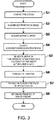
- Fig. 3 is a flowchart illustrating the operation of the failure diagnosis device of Fig. 1 .
- the failure diagnosis device 1 acquires time (cycle) (Step S1).
- the rotation speed acquiring module 2 acquires the rotation speed of the motor 14 (Step S2).
- the motor current acquiring module 4 acquires the motor current of the motor 14 (Step S3).
- Step S1 time acquisition
- Step S2 rotation speed acquisition
- Step S3 motor current acquisition
- the acceleration/deceleration period identifying module 3 identifies the acceleration/deceleration period based on the rotation speed of the motor acquired by the rotation speed acquiring module 2 (Step S4).
- the time series rotation speed data generating module 5 sequentially samples the rotation speed of the motor acquired by the rotation speed acquiring module 2 during the acceleration/deceleration period, and generates the group of time series rotation speed data.
- the time series motor current data generating module 6 sequentially samples the motor current acquired by the motor current acquiring module 4 during the acceleration/deceleration period, and generates the group of time series motor current data (Step S5).
- the failure diagnosis device 1 determines the sampling frequency beforehand. Moreover, the number of sampling points in one revolution of the motor is defined.
- the FFT analyzing module 7 makes the group of time series motor current data correspond to the group of time series rotation speed data, conducts a frequency analysis of the group of time series motor current data, and generates the frequency spectra 22 of the group of motor current data corresponding to the group of time series rotation speed data 21 (Step S6).
- the amplitude peak value extracting module 8 extracts the peak value 24 of the amplitude of the motor current within the given frequency range fr corresponding to the given specific frequency f0 of the reduction gear 13 from the frequency spectra 22 of the group of motor current data.
- the determining module 9 compares the extracted peak value 24 of the amplitude of the motor current with the given amplitude threshold, and then determines whether the reduction gear 13 indicates the sign of failure based on the determination result. Specifically, if the peak value 24 of the amplitude of the motor current is above the given amplitude threshold, the determining module 9 determines that the reduction gear 13 indicates the sign of failure, and if the peak value 24 of the amplitude of the motor current is below the given amplitude threshold, the determining module 9 determines that the reduction gear 13 does not indicate the sign of failure.
- the acceleration/deceleration period during which the operation of the mechanical apparatus 11 accelerates and/or decelerates can be identified.
- the current amplitude within the particular frequency range fr corresponding to the specific frequency f0 of the reduction gear 13 increases by the resonance of the reduction gear 13, and presents the peak value 24.
- This peak value 24 has the correlation with the sign of failure of the reduction gear 13. Therefore, it can be determined whether the reduction gear 13 indicates the sign of failure based on the change in the frequency spectrum S of the motor current data with respect to the change in the rotation speed data R of the motor 14. Therefore, the failure diagnosis can be performed during the work of the mechanical apparatus 11 provided with the reduction gear 13.
- the failure diagnosis device 1 is configured to determine whether the reduction gear 13 indicates the sign of failure when the motor current is above the given value.
- the given value is determined by an experiment, a simulation, etc.
- the timing at which the failure diagnosis device 1 determines whether the motor current is above the given value may be any timing as long as the timing is between Step S3 where the motor current is acquired and Step S8 where the existence of the sign of failure is determined.
- the acceleration/deceleration period is used as an acceleration period.
- the existence of the sign of failure is determined during the acceleration period of the operation of the mechanical apparatus 11.
- the peak value 24 of the current amplitude within the particular frequency range fr by the resonance of the reduction gear appears more clearly. Therefore, the existence of the sign of failure can be determined more accurately.
- a mechanical apparatus 11 according to Embodiment 2 of the present disclosure is provided with the failure diagnosis device 1 for the reduction gear 13 of any one of Embodiment 1, Modification 1 and Modification 2.
- the failure diagnosis can be performed during the work of the mechanical apparatus 11.
- the present inventors conducted a durability test of a reduction gear for an industrial robot, in order to examine the validity of the failure diagnosis device and the method of diagnosing the failure of the present disclosure.
- a reduction gear of the second joint is used as a target of the durability test.
- the change in the amplitude of the motor current within the particular frequency range corresponding to the specific frequency of the reduction gear with respect to the change in the iron powder concentration of the grease filled in the reduction gear was examined.
- a 6-axis articulated robot was used as the industrial robot.
- the durability test was conducted with the robot taking a posture in which a large load is applied to the reduction gear and the motor of the second joint. That is, the robot took the posture in which a robotic arm is stretched substantially horizontally.
- an abrasion (worn) state of the reduction gear of the second joint was examined.
- the examination of the abrasion state was conducted by periodically examining the iron powder concentration of the grease filled in the reduction gear.
- the 3D frequency analysis (refer to Fig. 2 ) described above was also conducted for the current instruction value of the motor to drive the reduction gear.
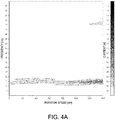
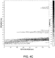
- Figs. 4A to 4E are views illustrating a correlation between the iron powder concentration of the grease for the reduction gear in the durability test and the peak value of the amplitude of the motor current within the particular frequency range corresponding to the specific frequency of the reduction gear.
- Figs. 4A to 4E are a view of the iron powder concentration being 0.008wt%, a view of the iron powder concentration being 0.057wt%, a view of the iron powder concentration being 0.104wt%, a view of the iron powder concentration being 0.176wt%, and a view of the iron powder concentration being 0.290wt%, respectively.
- the durability test advances from Fig. 4A to Fig. 4E .
- X-axis expresses the rotation speed (rpm) of the motor
- Y-axis expresses the frequency
- a gradation of the image expresses the amplitude (A) of the motor current.
- the amplitude of the motor current is larger as the image becomes deeper (black), and the amplitude of the motor current is smaller as the image is lighter (white).
- a range where the amplitude of the motor current is large appears near 14Hz, and it can be seen that the amplitude of the motor current becomes larger (the image becomes deeper) as the durability test advances. That is, it can be seen that the amplitude of the motor current presents the peak value. Moreover, it can be seen that the iron powder concentration of the grease increases as the durability test advances.
- Fig. 5 is a view illustrating the correlation between the iron powder concentration of the grease for the reduction gear in the durability test and the peak value of the amplitude of the motor current within the particular frequency range corresponding to the specific frequency of the reduction gear.
- the horizontal axis expresses the iron powder concentration
- the vertical axis expresses the peak value of the amplitude of the motor current. From Fig. 5 , it can be seen that a correlation exists between the iron powder concentration of the grease for the reduction gear and the peak value of the amplitude of the motor current within the particular frequency range corresponding to the specific frequency of the reduction gear. In other words, it can be seen that the peak value of the amplitude of the motor current within the particular frequency range correlates with the sign of failure of the reduction gear.
- the failure diagnosis device etc. for the reduction gear of the present disclosure is useful as the failure diagnosis device etc. for the reduction gear which is capable of performing the failure diagnosis during the work of the mechanical apparatus provided with the reduction gear.
Landscapes
- Engineering & Computer Science (AREA)
- Robotics (AREA)
- Mechanical Engineering (AREA)
- Physics & Mathematics (AREA)
- General Physics & Mathematics (AREA)
- Testing Of Devices, Machine Parts, Or Other Structures Thereof (AREA)
- Control Of Electric Motors In General (AREA)
- Manipulator (AREA)
Applications Claiming Priority (2)
| Application Number | Priority Date | Filing Date | Title |
|---|---|---|---|
| JP2016253970A JP6144404B1 (ja) | 2016-12-27 | 2016-12-27 | 減速機の故障診断装置及び故障診断方法並びに前記故障診断装置を備える機械装置 |
| PCT/JP2017/046908 WO2018124182A1 (fr) | 2016-12-27 | 2017-12-27 | Dispositif et procédé de diagnostic de défaut pour réducteurs de vitesse et dispositif mécanique comprenant ledit dispositif de diagnostic de défaut |
Publications (3)
| Publication Number | Publication Date |
|---|---|
| EP3563992A1 true EP3563992A1 (fr) | 2019-11-06 |
| EP3563992A4 EP3563992A4 (fr) | 2020-08-19 |
| EP3563992B1 EP3563992B1 (fr) | 2025-04-23 |
Family
ID=59012069
Family Applications (1)
| Application Number | Title | Priority Date | Filing Date |
|---|---|---|---|
| EP17885804.9A Active EP3563992B1 (fr) | 2016-12-27 | 2017-12-27 | Dispositif et procédé de diagnostic de défaut pour réducteurs de vitesse et dispositif mécanique comprenant ledit dispositif de diagnostic de défaut |
Country Status (6)
| Country | Link |
|---|---|
| US (2) | US12152960B2 (fr) |
| EP (1) | EP3563992B1 (fr) |
| JP (1) | JP6144404B1 (fr) |
| KR (3) | KR20210043738A (fr) |
| CN (1) | CN110139733B (fr) |
| WO (1) | WO2018124182A1 (fr) |
Families Citing this family (38)
| Publication number | Priority date | Publication date | Assignee | Title |
|---|---|---|---|---|
| US11314241B2 (en) | 2016-06-07 | 2022-04-26 | Mitsubishi Electric Corporation | Abnormality diagnosis apparatus and abnormality diagnosis method |
| JP6628905B2 (ja) * | 2016-12-15 | 2020-01-15 | 三菱電機株式会社 | 動力伝達機構の異常診断装置および動力伝達機構の異常診断方法 |
| CN107228764A (zh) * | 2017-06-28 | 2017-10-03 | 重庆大学 | 精密行星减速器扭转刚度及回差测量系统 |
| WO2019017345A1 (fr) * | 2017-07-18 | 2019-01-24 | 日本電気株式会社 | Dispositif, procédé et programme d'estimation d'état |
| CN107271183A (zh) * | 2017-07-18 | 2017-10-20 | 芜湖赛宝机器人产业技术研究院有限公司 | 一种工业机器人减速机扭转刚度试验台 |
| JP6812925B2 (ja) * | 2017-08-01 | 2021-01-13 | トヨタ自動車株式会社 | ロボットアーム、鉄粉量推定方法及び異常予兆判定システム |
| EP3444585B1 (fr) * | 2017-08-17 | 2020-05-27 | ALSTOM Transport Technologies | Procédé pour déterminer l'état d'un palier, module pour déterminer l'état d'un palier, véhicule ferroviaire et système |
| EP3760999A4 (fr) * | 2018-02-28 | 2021-03-17 | Nissan Motor Co., Ltd. | Dispositif de détermination de type d'anomalie et procédé de détermination de type d'anomalie |
| JP6940820B2 (ja) * | 2018-05-08 | 2021-09-29 | オムロン株式会社 | ロボット制御装置、保守管理方法、及び保守管理プログラム |
| JP7516013B2 (ja) * | 2018-07-24 | 2024-07-16 | キヤノン株式会社 | 処理装置、生産システム、ロボット装置、物品の製造方法、処理方法、プログラム及び記録媒体 |
| US11789437B2 (en) | 2018-07-24 | 2023-10-17 | Canon Kabushiki Kaisha | Processing apparatus and processing method for processing portion |
| JP2020067334A (ja) * | 2018-10-23 | 2020-04-30 | 三菱重工業株式会社 | 異常診断装置及び異常診断方法 |
| JP7309344B2 (ja) * | 2018-11-13 | 2023-07-18 | 川崎重工業株式会社 | 駆動機構の故障診断装置及び故障診断方法並びに前記故障診断装置を備える機械装置 |
| KR102154987B1 (ko) * | 2018-12-31 | 2020-09-11 | 주식회사 인팩 | 기어구동 액추에이터 장치의 고장 판별 방법 및 장치 |
| JP7280703B2 (ja) * | 2019-01-31 | 2023-05-24 | 住友重機械工業株式会社 | 診断システム |
| EP3901723A4 (fr) | 2019-02-07 | 2022-01-05 | Honda Motor Co., Ltd. | Machine de travail, procédé de commande de machine de travail, et programme |
| CN110056640B (zh) * | 2019-04-12 | 2021-07-06 | 苏芯物联技术(南京)有限公司 | 基于加速度信号和边缘计算的减速机无线故障诊断方法 |
| JP7351656B2 (ja) * | 2019-06-28 | 2023-09-27 | 川崎重工業株式会社 | 減速機の故障診断装置及び故障診断方法 |
| KR102254934B1 (ko) * | 2019-07-30 | 2021-05-25 | 한국생산기술연구원 | 로봇 관절부 고장진단 방법 및 이를 적용한 로봇 관절부 고장 진단 시스템 |
| CN110793771A (zh) * | 2019-10-18 | 2020-02-14 | 中国直升机设计研究所 | 一种模拟直升机主减速器故障的试验台 |
| CN110871458B (zh) * | 2019-11-29 | 2022-03-25 | 北京猎户星空科技有限公司 | 机器人传动机构的测试方法、装置、设备及介质 |
| CN111145388B (zh) * | 2019-12-30 | 2021-11-19 | 潍柴动力股份有限公司 | 一种缓速器诊断方法、装置、设备及存储介质 |
| CN111337767B (zh) * | 2020-02-25 | 2023-07-18 | 河北工业大学 | 一种谐振波减速器故障分析方法 |
| KR102322748B1 (ko) | 2020-04-13 | 2021-11-08 | 케이티엠엔지니어링(주) | 동력 대차, 차축 베어링 및 감속기용 탐지 장치 |
| JP2021197158A (ja) * | 2020-06-15 | 2021-12-27 | 三菱パワー株式会社 | 予兆判定装置、予兆判定システム、予兆判定方法及びプログラム |
| KR102383001B1 (ko) | 2020-07-27 | 2022-04-05 | 케이티엠엔지니어링(주) | 감속기 탐지 시스템 |
| KR102524833B1 (ko) * | 2020-11-20 | 2023-04-24 | 주식회사 제우스 | 액추에이터 모듈의 성능을 평가하기 위한 평가 장치 |
| CN113021413A (zh) * | 2021-02-23 | 2021-06-25 | 埃夫特智能装备股份有限公司 | 一种工业机器人用谐波减速器刚度一致性测量装置 |
| JP7245866B2 (ja) * | 2021-04-26 | 2023-03-24 | 三菱重工業株式会社 | 風車翼の診断方法 |
| KR102574551B1 (ko) | 2021-05-04 | 2023-09-06 | 케이티엠엔지니어링(주) | 철도 차량용 감속기 작동 상태 진단 시스템 |
| CN113341914B (zh) * | 2021-05-24 | 2022-06-28 | 潍柴动力股份有限公司 | 一种发动机的计时处理方法、系统及装置 |
| KR102669406B1 (ko) | 2021-09-06 | 2024-05-27 | 케이티엠엔지니어링(주) | 인공지능 적용 방식의 감속기 모니터링 시스템 |
| KR102558023B1 (ko) | 2021-10-14 | 2023-07-20 | 케이티엠엔지니어링(주) | 열차 감속기의 작동 상태 탐지에 따른 구조 진단 시스템 |
| CN115042227B (zh) * | 2022-05-30 | 2025-09-19 | 广州风神汽车有限公司 | 减速机的维护方法、维护装置以及存储介质 |
| CN115638979B (zh) * | 2022-11-14 | 2026-04-07 | 江苏师范大学 | 一种基于机电耦合模型的齿轮裂纹故障诊断方法 |
| CN118655400B (zh) * | 2024-08-16 | 2024-10-29 | 河北工业大学 | 一种重载工业机器人关节减速器故障检测方法 |
| JP2026047561A (ja) | 2024-09-04 | 2026-03-16 | 日立Geベルノバニュークリアエナジー株式会社 | 制御棒駆動装置の異常検知装置、異常検知方法、及び、プログラム |
| CN120105356B (zh) * | 2025-05-09 | 2025-09-02 | 唐智科技湖南发展有限公司 | 一种齿轮崩断识别方法、装置、设备及介质 |
Family Cites Families (13)
| Publication number | Priority date | Publication date | Assignee | Title |
|---|---|---|---|---|
| JP2000146771A (ja) * | 1998-11-18 | 2000-05-26 | Nippon Steel Corp | 加減速型回転機械設備の簡易異常診断方法 |
| JP4112594B2 (ja) | 2006-07-27 | 2008-07-02 | ファナック株式会社 | 減速機異常診断方法及び減速機異常診断装置 |
| JP5069923B2 (ja) * | 2007-02-28 | 2012-11-07 | 株式会社日立産機システム | 異常診断機能付きホイストクレーン装置 |
| US8384332B2 (en) * | 2008-12-22 | 2013-02-26 | Texas Instruments Incorporated | Integrated gearbox/encoder and control system |
| SE534091C2 (sv) * | 2009-05-20 | 2011-04-26 | Ind Service Applic Isa Ab | Metod och system för att utvärdera spelet mellan två gängade komponenter. |
| JP5482699B2 (ja) * | 2011-03-16 | 2014-05-07 | トヨタ自動車株式会社 | 減速機異常診断装置および減速機異常診断方法 |
| JP2013144325A (ja) * | 2012-01-13 | 2013-07-25 | Seiko Epson Corp | ロボット装置、故障検出方法 |
| FR2986070B1 (fr) * | 2012-01-24 | 2014-11-28 | Snecma | Systeme d'acquisition d'un signal vibratoire d'un moteur rotatif |
| JP6120720B2 (ja) * | 2013-08-09 | 2017-04-26 | 株式会社神戸製鋼所 | 周波数分析方法、及びこの周波数分析方法を用いた回転機器の診断方法 |
| JP6418782B2 (ja) * | 2014-05-16 | 2018-11-07 | キヤノン株式会社 | ロボットシステムの制御方法、プログラム、記録媒体、ロボットシステム、及び診断装置 |
| JP2016179527A (ja) * | 2015-03-24 | 2016-10-13 | ファナック株式会社 | ロボットの異常診断を行う機能を有するロボット制御装置 |
| JP6017649B2 (ja) * | 2015-08-10 | 2016-11-02 | 株式会社高田工業所 | 回転機械系の異常診断方法 |
| US11314241B2 (en) * | 2016-06-07 | 2022-04-26 | Mitsubishi Electric Corporation | Abnormality diagnosis apparatus and abnormality diagnosis method |
-
2016
- 2016-12-27 JP JP2016253970A patent/JP6144404B1/ja active Active
-
2017
- 2017-12-27 KR KR1020217010842A patent/KR20210043738A/ko not_active Ceased
- 2017-12-27 KR KR1020227033162A patent/KR20220134665A/ko not_active Ceased
- 2017-12-27 CN CN201780080460.1A patent/CN110139733B/zh active Active
- 2017-12-27 WO PCT/JP2017/046908 patent/WO2018124182A1/fr not_active Ceased
- 2017-12-27 KR KR1020197011505A patent/KR20190083648A/ko not_active Ceased
- 2017-12-27 US US16/474,477 patent/US12152960B2/en active Active
- 2017-12-27 EP EP17885804.9A patent/EP3563992B1/fr active Active
-
2024
- 2024-10-17 US US18/918,776 patent/US20250035512A1/en active Pending
Also Published As
| Publication number | Publication date |
|---|---|
| US20250035512A1 (en) | 2025-01-30 |
| JP2018105782A (ja) | 2018-07-05 |
| KR20210043738A (ko) | 2021-04-21 |
| US12152960B2 (en) | 2024-11-26 |
| CN110139733B (zh) | 2023-01-03 |
| KR20190083648A (ko) | 2019-07-12 |
| JP6144404B1 (ja) | 2017-06-07 |
| KR20220134665A (ko) | 2022-10-05 |
| EP3563992B1 (fr) | 2025-04-23 |
| CN110139733A (zh) | 2019-08-16 |
| WO2018124182A1 (fr) | 2018-07-05 |
| US20190339161A1 (en) | 2019-11-07 |
| EP3563992A4 (fr) | 2020-08-19 |
Similar Documents
| Publication | Publication Date | Title |
|---|---|---|
| US20250035512A1 (en) | Failure diagnosis device for reduction gear, method of diagnosing failure, and mechanical apparatus provided with the failure diagnosis device | |
| EP1882922B1 (fr) | Procédé de diagnostic des anomalies d'engrenage de réduction et appareil pour mettre en oeuvre le procédé | |
| EP3881989A1 (fr) | Dispositif de diagnostic de défaillance pour mécanisme d'entraînement, procédé de diagnostic de défaillance et appareil mécanique pourvu d'un dispositif de diagnostic de défaillance | |
| EP3888855B1 (fr) | Procédé et appareil de prédiction de défaillance | |
| EP3462602B1 (fr) | Procédé et appareil de surveillance de l'état en ligne d'applications de moteur à vitesse variable | |
| US20170242076A1 (en) | Abnormality determining apparatus, abnormality determining method, and abnormality determining system | |
| JP7351656B2 (ja) | 減速機の故障診断装置及び故障診断方法 | |
| KR20180073500A (ko) | 잔여 공간 내의 진동 역학의 모델링 및 시각화 | |
| JP2002268728A (ja) | 同期診断監視システム、同期診断監視装置、および同期診断監視プログラム | |
| EP3760999A1 (fr) | Dispositif de détermination de type d'anomalie et procédé de détermination de type d'anomalie | |
| JP2019024305A (ja) | モータ制御システム | |
| JP4073902B2 (ja) | 電動弁装置の異常および劣化診断手法ならびに装置 | |
| CN119734311A (zh) | 用于诊断机器人的方法和设备 | |
| US20240411283A1 (en) | Anomaly diagnosis apparatus and anomaly diagnosis method | |
| JP7245994B2 (ja) | 異常診断装置及びそれを備えたロボット制御装置 | |
| CN106940540B (zh) | 控制器、设备的控制和状态监测方法 | |
| JP2020025461A (ja) | モータ制御システム | |
| JP2007122575A (ja) | モータ制御装置 | |
| Epure et al. | VIBROGEN-An experimental system to study vibration waveforms generated by faults under arbitrary load conditions | |
| EP4235197A1 (fr) | Procédé et système de diagnostic d'une machine | |
| JP2005346455A (ja) | モータ制御装置 | |
| JP2010169421A (ja) | ジンバルのマスアンバランス測定装置および方法 |
Legal Events
| Date | Code | Title | Description |
|---|---|---|---|
| STAA | Information on the status of an ep patent application or granted ep patent |
Free format text: STATUS: THE INTERNATIONAL PUBLICATION HAS BEEN MADE |
|
| PUAI | Public reference made under article 153(3) epc to a published international application that has entered the european phase |
Free format text: ORIGINAL CODE: 0009012 |
|
| STAA | Information on the status of an ep patent application or granted ep patent |
Free format text: STATUS: REQUEST FOR EXAMINATION WAS MADE |
|
| 17P | Request for examination filed |
Effective date: 20190722 |
|
| AK | Designated contracting states |
Kind code of ref document: A1 Designated state(s): AL AT BE BG CH CY CZ DE DK EE ES FI FR GB GR HR HU IE IS IT LI LT LU LV MC MK MT NL NO PL PT RO RS SE SI SK SM TR |
|
| AX | Request for extension of the european patent |
Extension state: BA ME |
|
| DAV | Request for validation of the european patent (deleted) | ||
| DAX | Request for extension of the european patent (deleted) | ||
| A4 | Supplementary search report drawn up and despatched |
Effective date: 20200716 |
|
| RIC1 | Information provided on ipc code assigned before grant |
Ipc: B25J 19/06 20060101AFI20200710BHEP Ipc: G01M 13/021 20190101ALI20200710BHEP |
|
| STAA | Information on the status of an ep patent application or granted ep patent |
Free format text: STATUS: EXAMINATION IS IN PROGRESS |
|
| 17Q | First examination report despatched |
Effective date: 20221020 |
|
| GRAP | Despatch of communication of intention to grant a patent |
Free format text: ORIGINAL CODE: EPIDOSNIGR1 |
|
| STAA | Information on the status of an ep patent application or granted ep patent |
Free format text: STATUS: GRANT OF PATENT IS INTENDED |
|
| INTG | Intention to grant announced |
Effective date: 20241125 |
|
| GRAS | Grant fee paid |
Free format text: ORIGINAL CODE: EPIDOSNIGR3 |
|
| GRAA | (expected) grant |
Free format text: ORIGINAL CODE: 0009210 |
|
| STAA | Information on the status of an ep patent application or granted ep patent |
Free format text: STATUS: THE PATENT HAS BEEN GRANTED |
|
| AK | Designated contracting states |
Kind code of ref document: B1 Designated state(s): AL AT BE BG CH CY CZ DE DK EE ES FI FR GB GR HR HU IE IS IT LI LT LU LV MC MK MT NL NO PL PT RO RS SE SI SK SM TR |
|
| REG | Reference to a national code |
Ref country code: GB Ref legal event code: FG4D |
|
| REG | Reference to a national code |
Ref country code: CH Ref legal event code: EP |
|
| REG | Reference to a national code |
Ref country code: DE Ref legal event code: R096 Ref document number: 602017089103 Country of ref document: DE |
|
| REG | Reference to a national code |
Ref country code: IE Ref legal event code: FG4D |
|
| REG | Reference to a national code |
Ref country code: NL Ref legal event code: MP Effective date: 20250423 |
|
| PG25 | Lapsed in a contracting state [announced via postgrant information from national office to epo] |
Ref country code: NL Free format text: LAPSE BECAUSE OF FAILURE TO SUBMIT A TRANSLATION OF THE DESCRIPTION OR TO PAY THE FEE WITHIN THE PRESCRIBED TIME-LIMIT Effective date: 20250423 |
|
| REG | Reference to a national code |
Ref country code: AT Ref legal event code: MK05 Ref document number: 1787359 Country of ref document: AT Kind code of ref document: T Effective date: 20250423 |
|
| PG25 | Lapsed in a contracting state [announced via postgrant information from national office to epo] |
Ref country code: FI Free format text: LAPSE BECAUSE OF FAILURE TO SUBMIT A TRANSLATION OF THE DESCRIPTION OR TO PAY THE FEE WITHIN THE PRESCRIBED TIME-LIMIT Effective date: 20250423 Ref country code: ES Free format text: LAPSE BECAUSE OF FAILURE TO SUBMIT A TRANSLATION OF THE DESCRIPTION OR TO PAY THE FEE WITHIN THE PRESCRIBED TIME-LIMIT Effective date: 20250423 Ref country code: PT Free format text: LAPSE BECAUSE OF FAILURE TO SUBMIT A TRANSLATION OF THE DESCRIPTION OR TO PAY THE FEE WITHIN THE PRESCRIBED TIME-LIMIT Effective date: 20250825 |
|
| REG | Reference to a national code |
Ref country code: LT Ref legal event code: MG9D |
|
| PG25 | Lapsed in a contracting state [announced via postgrant information from national office to epo] |
Ref country code: NO Free format text: LAPSE BECAUSE OF FAILURE TO SUBMIT A TRANSLATION OF THE DESCRIPTION OR TO PAY THE FEE WITHIN THE PRESCRIBED TIME-LIMIT Effective date: 20250723 Ref country code: GR Free format text: LAPSE BECAUSE OF FAILURE TO SUBMIT A TRANSLATION OF THE DESCRIPTION OR TO PAY THE FEE WITHIN THE PRESCRIBED TIME-LIMIT Effective date: 20250724 |
|
| PG25 | Lapsed in a contracting state [announced via postgrant information from national office to epo] |
Ref country code: PL Free format text: LAPSE BECAUSE OF FAILURE TO SUBMIT A TRANSLATION OF THE DESCRIPTION OR TO PAY THE FEE WITHIN THE PRESCRIBED TIME-LIMIT Effective date: 20250423 |
|
| PG25 | Lapsed in a contracting state [announced via postgrant information from national office to epo] |
Ref country code: BG Free format text: LAPSE BECAUSE OF FAILURE TO SUBMIT A TRANSLATION OF THE DESCRIPTION OR TO PAY THE FEE WITHIN THE PRESCRIBED TIME-LIMIT Effective date: 20250423 |
|
| PG25 | Lapsed in a contracting state [announced via postgrant information from national office to epo] |
Ref country code: HR Free format text: LAPSE BECAUSE OF FAILURE TO SUBMIT A TRANSLATION OF THE DESCRIPTION OR TO PAY THE FEE WITHIN THE PRESCRIBED TIME-LIMIT Effective date: 20250423 |
|
| PG25 | Lapsed in a contracting state [announced via postgrant information from national office to epo] |
Ref country code: AT Free format text: LAPSE BECAUSE OF FAILURE TO SUBMIT A TRANSLATION OF THE DESCRIPTION OR TO PAY THE FEE WITHIN THE PRESCRIBED TIME-LIMIT Effective date: 20250423 |
|
| PG25 | Lapsed in a contracting state [announced via postgrant information from national office to epo] |
Ref country code: RS Free format text: LAPSE BECAUSE OF FAILURE TO SUBMIT A TRANSLATION OF THE DESCRIPTION OR TO PAY THE FEE WITHIN THE PRESCRIBED TIME-LIMIT Effective date: 20250723 |
|
| PG25 | Lapsed in a contracting state [announced via postgrant information from national office to epo] |
Ref country code: IS Free format text: LAPSE BECAUSE OF FAILURE TO SUBMIT A TRANSLATION OF THE DESCRIPTION OR TO PAY THE FEE WITHIN THE PRESCRIBED TIME-LIMIT Effective date: 20250823 |
|
| PG25 | Lapsed in a contracting state [announced via postgrant information from national office to epo] |
Ref country code: LV Free format text: LAPSE BECAUSE OF FAILURE TO SUBMIT A TRANSLATION OF THE DESCRIPTION OR TO PAY THE FEE WITHIN THE PRESCRIBED TIME-LIMIT Effective date: 20250423 |
|
| PGFP | Annual fee paid to national office [announced via postgrant information from national office to epo] |
Ref country code: GB Payment date: 20251223 Year of fee payment: 9 |
|
| PG25 | Lapsed in a contracting state [announced via postgrant information from national office to epo] |
Ref country code: DK Free format text: LAPSE BECAUSE OF FAILURE TO SUBMIT A TRANSLATION OF THE DESCRIPTION OR TO PAY THE FEE WITHIN THE PRESCRIBED TIME-LIMIT Effective date: 20250423 Ref country code: SM Free format text: LAPSE BECAUSE OF FAILURE TO SUBMIT A TRANSLATION OF THE DESCRIPTION OR TO PAY THE FEE WITHIN THE PRESCRIBED TIME-LIMIT Effective date: 20250423 |
|
| PGFP | Annual fee paid to national office [announced via postgrant information from national office to epo] |
Ref country code: FR Payment date: 20251223 Year of fee payment: 9 |
|
| PG25 | Lapsed in a contracting state [announced via postgrant information from national office to epo] |
Ref country code: CZ Free format text: LAPSE BECAUSE OF FAILURE TO SUBMIT A TRANSLATION OF THE DESCRIPTION OR TO PAY THE FEE WITHIN THE PRESCRIBED TIME-LIMIT Effective date: 20250423 |
|
| PG25 | Lapsed in a contracting state [announced via postgrant information from national office to epo] |
Ref country code: EE Free format text: LAPSE BECAUSE OF FAILURE TO SUBMIT A TRANSLATION OF THE DESCRIPTION OR TO PAY THE FEE WITHIN THE PRESCRIBED TIME-LIMIT Effective date: 20250423 |
|
| REG | Reference to a national code |
Ref country code: DE Ref legal event code: R097 Ref document number: 602017089103 Country of ref document: DE |
|
| PG25 | Lapsed in a contracting state [announced via postgrant information from national office to epo] |
Ref country code: SK Free format text: LAPSE BECAUSE OF FAILURE TO SUBMIT A TRANSLATION OF THE DESCRIPTION OR TO PAY THE FEE WITHIN THE PRESCRIBED TIME-LIMIT Effective date: 20250423 Ref country code: RO Free format text: LAPSE BECAUSE OF FAILURE TO SUBMIT A TRANSLATION OF THE DESCRIPTION OR TO PAY THE FEE WITHIN THE PRESCRIBED TIME-LIMIT Effective date: 20250423 |
|
| PG25 | Lapsed in a contracting state [announced via postgrant information from national office to epo] |
Ref country code: IT Free format text: LAPSE BECAUSE OF FAILURE TO SUBMIT A TRANSLATION OF THE DESCRIPTION OR TO PAY THE FEE WITHIN THE PRESCRIBED TIME-LIMIT Effective date: 20250423 |
|
| PLBE | No opposition filed within time limit |
Free format text: ORIGINAL CODE: 0009261 |
|
| STAA | Information on the status of an ep patent application or granted ep patent |
Free format text: STATUS: NO OPPOSITION FILED WITHIN TIME LIMIT |
|
| REG | Reference to a national code |
Ref country code: CH Ref legal event code: L10 Free format text: ST27 STATUS EVENT CODE: U-0-0-L10-L00 (AS PROVIDED BY THE NATIONAL OFFICE) Effective date: 20260304 |
|
| 26N | No opposition filed |
Effective date: 20260126 |
|
| PGFP | Annual fee paid to national office [announced via postgrant information from national office to epo] |
Ref country code: DE Payment date: 20251223 Year of fee payment: 9 |