EP3564006A1 - Vorrichtung zum transport und prüfen von vorformlingen - Google Patents
Vorrichtung zum transport und prüfen von vorformlingen Download PDFInfo
- Publication number
- EP3564006A1 EP3564006A1 EP19171304.9A EP19171304A EP3564006A1 EP 3564006 A1 EP3564006 A1 EP 3564006A1 EP 19171304 A EP19171304 A EP 19171304A EP 3564006 A1 EP3564006 A1 EP 3564006A1
- Authority
- EP
- European Patent Office
- Prior art keywords
- preforms
- preform
- conveyor belt
- transport
- conveyor
- Prior art date
- Legal status (The legal status is an assumption and is not a legal conclusion. Google has not performed a legal analysis and makes no representation as to the accuracy of the status listed.)
- Granted
Links
Images

Classifications
-
- B—PERFORMING OPERATIONS; TRANSPORTING
- B29—WORKING OF PLASTICS; WORKING OF SUBSTANCES IN A PLASTIC STATE IN GENERAL
- B29C—SHAPING OR JOINING OF PLASTICS; SHAPING OF MATERIAL IN A PLASTIC STATE, NOT OTHERWISE PROVIDED FOR; AFTER-TREATMENT OF THE SHAPED PRODUCTS, e.g. REPAIRING
- B29C49/00—Blow-moulding, i.e. blowing a preform or parison to a desired shape within a mould; Apparatus therefor
- B29C49/42—Component parts, details or accessories; Auxiliary operations
- B29C49/4205—Handling means, e.g. transfer, loading or discharging means
-
- B—PERFORMING OPERATIONS; TRANSPORTING
- B29—WORKING OF PLASTICS; WORKING OF SUBSTANCES IN A PLASTIC STATE IN GENERAL
- B29C—SHAPING OR JOINING OF PLASTICS; SHAPING OF MATERIAL IN A PLASTIC STATE, NOT OTHERWISE PROVIDED FOR; AFTER-TREATMENT OF THE SHAPED PRODUCTS, e.g. REPAIRING
- B29C2949/00—Indexing scheme relating to blow-moulding
- B29C2949/07—Preforms or parisons characterised by their configuration
- B29C2949/0715—Preforms or parisons characterised by their configuration the preform having one end closed
-
- B—PERFORMING OPERATIONS; TRANSPORTING
- B29—WORKING OF PLASTICS; WORKING OF SUBSTANCES IN A PLASTIC STATE IN GENERAL
- B29C—SHAPING OR JOINING OF PLASTICS; SHAPING OF MATERIAL IN A PLASTIC STATE, NOT OTHERWISE PROVIDED FOR; AFTER-TREATMENT OF THE SHAPED PRODUCTS, e.g. REPAIRING
- B29C49/00—Blow-moulding, i.e. blowing a preform or parison to a desired shape within a mould; Apparatus therefor
- B29C49/02—Combined blow-moulding and manufacture of the preform or the parison
- B29C49/06—Injection blow-moulding
-
- B—PERFORMING OPERATIONS; TRANSPORTING
- B29—WORKING OF PLASTICS; WORKING OF SUBSTANCES IN A PLASTIC STATE IN GENERAL
- B29C—SHAPING OR JOINING OF PLASTICS; SHAPING OF MATERIAL IN A PLASTIC STATE, NOT OTHERWISE PROVIDED FOR; AFTER-TREATMENT OF THE SHAPED PRODUCTS, e.g. REPAIRING
- B29C49/00—Blow-moulding, i.e. blowing a preform or parison to a desired shape within a mould; Apparatus therefor
- B29C49/42—Component parts, details or accessories; Auxiliary operations
- B29C49/4205—Handling means, e.g. transfer, loading or discharging means
- B29C49/42073—Grippers
- B29C49/42079—Grippers using vacuum for gripping
-
- B—PERFORMING OPERATIONS; TRANSPORTING
- B29—WORKING OF PLASTICS; WORKING OF SUBSTANCES IN A PLASTIC STATE IN GENERAL
- B29C—SHAPING OR JOINING OF PLASTICS; SHAPING OF MATERIAL IN A PLASTIC STATE, NOT OTHERWISE PROVIDED FOR; AFTER-TREATMENT OF THE SHAPED PRODUCTS, e.g. REPAIRING
- B29C49/00—Blow-moulding, i.e. blowing a preform or parison to a desired shape within a mould; Apparatus therefor
- B29C49/42—Component parts, details or accessories; Auxiliary operations
- B29C49/4205—Handling means, e.g. transfer, loading or discharging means
- B29C49/42073—Grippers
- B29C49/42089—Grippers holding body portion
-
- B—PERFORMING OPERATIONS; TRANSPORTING
- B29—WORKING OF PLASTICS; WORKING OF SUBSTANCES IN A PLASTIC STATE IN GENERAL
- B29C—SHAPING OR JOINING OF PLASTICS; SHAPING OF MATERIAL IN A PLASTIC STATE, NOT OTHERWISE PROVIDED FOR; AFTER-TREATMENT OF THE SHAPED PRODUCTS, e.g. REPAIRING
- B29C49/00—Blow-moulding, i.e. blowing a preform or parison to a desired shape within a mould; Apparatus therefor
- B29C49/42—Component parts, details or accessories; Auxiliary operations
- B29C49/4205—Handling means, e.g. transfer, loading or discharging means
- B29C49/42093—Transporting apparatus, e.g. slides, wheels or conveyors
- B29C49/42097—Sliding rails, e.g. inclined
-
- B—PERFORMING OPERATIONS; TRANSPORTING
- B29—WORKING OF PLASTICS; WORKING OF SUBSTANCES IN A PLASTIC STATE IN GENERAL
- B29C—SHAPING OR JOINING OF PLASTICS; SHAPING OF MATERIAL IN A PLASTIC STATE, NOT OTHERWISE PROVIDED FOR; AFTER-TREATMENT OF THE SHAPED PRODUCTS, e.g. REPAIRING
- B29C49/00—Blow-moulding, i.e. blowing a preform or parison to a desired shape within a mould; Apparatus therefor
- B29C49/42—Component parts, details or accessories; Auxiliary operations
- B29C49/4205—Handling means, e.g. transfer, loading or discharging means
- B29C49/42093—Transporting apparatus, e.g. slides, wheels or conveyors
- B29C49/42101—Conveyors, e.g. flat conveyor or clamping between two bands
-
- B—PERFORMING OPERATIONS; TRANSPORTING
- B29—WORKING OF PLASTICS; WORKING OF SUBSTANCES IN A PLASTIC STATE IN GENERAL
- B29C—SHAPING OR JOINING OF PLASTICS; SHAPING OF MATERIAL IN A PLASTIC STATE, NOT OTHERWISE PROVIDED FOR; AFTER-TREATMENT OF THE SHAPED PRODUCTS, e.g. REPAIRING
- B29C49/00—Blow-moulding, i.e. blowing a preform or parison to a desired shape within a mould; Apparatus therefor
- B29C49/42—Component parts, details or accessories; Auxiliary operations
- B29C49/42378—Handling malfunction
- B29C49/4238—Ejecting defective preforms or products
-
- B—PERFORMING OPERATIONS; TRANSPORTING
- B29—WORKING OF PLASTICS; WORKING OF SUBSTANCES IN A PLASTIC STATE IN GENERAL
- B29L—INDEXING SCHEME ASSOCIATED WITH SUBCLASS B29C, RELATING TO PARTICULAR ARTICLES
- B29L2031/00—Other particular articles
- B29L2031/712—Containers; Packaging elements or accessories, Packages
- B29L2031/7158—Bottles
Definitions
- the invention relates to a device for occasional transport and testing of at least one test criterion of preforms during transport in a transport direction according to the preamble of claim 1.
- the invention relates to a device and a method for mass testing of geometrically matching preforms, so-called preforms, for the production of beverage bottles made of polyethylene terephthalate (PET).
- PET polyethylene terephthalate
- preforms are first produced by injection molding, including their closure thread. Subsequently, the preforms are processed into finished containers. For this purpose, the preform is heated, clamped in a mold, stretched to the final length and then brought into the final shape with compressed air. After cooling, the mold is opened and the finished container ejected.
- Faulty preforms cause production losses as well as additional material, energy and manufacturing costs. It is therefore desirable that the preforms used for container production are virtually error-free.
- Typical errors include dimensional errors, material defects and color errors. Dimensional errors can relate to the length, shape and diameter of the preforms. Material defects can be, for example, a faulty length of the injection point, incomplete molten material, bubbles, oil splashes and Impurities result. Color errors include color and intensity deviations as well as erroneous amounts of UV blockers.
- the examination unit has at least one control camera, a control unit connected thereto and a clamping conveyor.
- the clamping conveyor has two prestressed belts circulating around a respective drive wheel and a further wheel, which define a conveying path between them and which transport the separated, non-contacting hollow bodies in matching orientation to the at least one control camera along the transport path.
- the inspection camera looks from above on the front side of each hollow body and is connected to the control unit.
- the control unit receives data from the control camera, namely the image data of the individual hollow bodies and compares these with nominal values.
- the screening device is arranged so that it can act on the hollow body, the have left the examination unit.
- the rejection device ejects the hollow bodies approximately in the free throw, wherein the rejection device changes the trajectories of hollow bodies recognized as faulty and of hollow bodies recognized as faultless relative to one another by means of a non-contact exertion of force.
- the screening device has for this purpose a valve-controlled nozzle whose nozzle opening is directed to the trajectory of the hollow body.
- control unit If the control unit has identified a hollow body as having errors on the basis of the image data of the control camera, it sends a control signal to the valve and opens the nozzle at a time which is selected such that a compressed-air blast emerging from the nozzle strikes the hollow body when the latter has reached its effective range the nozzle of the screening device enters.
- the trajectory of a faulty hollow body thus differs from the trajectory of a recognized as faultless hollow body, so that error-free from faulty bodies can be separated.
- a disadvantage of the known device is that the instability of the hollow body during flight can lead to incorrect sorting.
- the separation of the faulty from the error-free hollow body by a change in their trajectory also has the consequence that completely coincide with the supply of the hollow body to the examination unit orientation of the hollow body and the information about the sequential order.
- An automated further processing of the sorted hollow body is therefore associated with great expense.
- the known device is only for Separation of faulty and error-free hollow bodies suitable.
- the EP 2 112 502 A1 discloses another method and apparatus for testing and sorting out preforms, wherein the preforms are checked for mechanical and optical defects and defective preforms are eliminated.
- the apparatus comprises a container for delivered preforms, a gripping device for receiving preforms from the container and their orientation with the mouth upwards, a belt conveyor for stabilizing the preforms and an optical examination unit with a device for rejecting unusable preforms.
- the optical examination unit has a vacuum conveying device with a perforated vacuum conveyor belt acted upon with vacuum on the rear, as well as various cameras and image processing. The rejection device releases the holding vacuum of the preforms identified as defective.
- the device has a container for unusable preforms and a container for tested and found to be perfect preforms.
- the belt conveyor transfers the vertically stabilized preforms successively to the vacuum conveyor of the optical inspection unit, which transports the preforms at their mouth and held exclusively by vacuum.
- the optical examination unit has three cameras, which are each offset at an angle of 120 ° in the image plane and a camera, which receives each preform from below. The cameras of the optical inspection unit allow a complete imaging of the outer surface of the preforms but not of the mouth area adjacent to the vacuum conveyor belt. In addition, this is also in this Tester lost the information about the sequential order of the tested and found faultless preforms.
- the invention has the object to provide a generic device, are avoided in the wrong sorting and the orientation of preforms with certain detected test criteria and their sequential order is maintained.
- a separation of the preforms for more than two test criteria is to be made possible with the device.
- a clamping conveyor belt in the examination unit ensures that the areas of each preform relevant to the test are not covered by components of the conveyor.
- the use of the clamping conveyor belt in the examination unit allows an arrangement of digital cameras which not only allow a preferably complete image of the outer surface of the preforms, but also the mouth region.
- the clamping conveyor which clamps the preforms close to the mouth, an unfavorable for the pictures of the images swing largely excluded.
- the rejection device has a vacuum conveyor belt, which connects the preforms with their mouth the vacuum conveyor belt by the prevailing negative pressure holds.
- the preforms therefore also adhere to the predetermined orientation and position in the screening device.
- a starting section of the vacuum conveyor belt is spaced above an end section of the clamping conveyor in the transport direction, in that the upwardly facing orifices of each preform on the vacuum conveyor belt in the overlapping region of the two conveyors get to the plant.
- the transport planes defined by the clamping conveyor and the vacuum conveyor are parallel to each other.
- All of the mouths of the preforms conveyed in the same position and orientation by the clamping conveyor are located a short distance below the transport plane defined by the vacuum conveyor belt, so that the preforms are sucked by the prevailing negative pressure and taken over by the vacuum conveyor belt.
- the screening device also has at least one release device that can be activated by a controller and that is set up to detach individual preforms from the vacuum conveyor belt. If, for example, individual preforms are identified as being defective by the data processing unit as a function of the evaluation of the image information representing the at least one test criterion, the control of the detachment device is activated and selectively removes the defective preform from the vacuum conveyor belt.
- the defect-free preforms are, however, transported further while maintaining their orientation and sequential order through the vacuum conveyor belt.
- a discharge conveyor arranged which takes over the preforms originating from the screening device, for example the preforms identified as faultless.
- the outlet conveyor has for this purpose two parallel spaced guide rails, wherein in the transport direction, an initial portion of the outlet conveyor is disposed below an end portion of the vacuum conveyor belt, so that the support ring of each preform arrives at the latest with the detachment of the preform at the end of the vacuum conveyor belt on the guide rails.
- a drive for the further transport of lying with the support ring on the guide rails preform can be omitted if the guide rails are inclined starting from the end portion of the vacuum belt down to effect the further transport of the preforms due to gravity.
- a separate drive for further transport of the preforms located in the guide rails may be provided, for example a compressed air drive.
- the preforms supplied to the outlet transport device retain their orientation and position as well as sequential order and can therefore be fed to automatic further processing with little effort, without the need for reorientation.
- the invention is based on the knowledge that a continuation of the form-fitting lateral guidance of the preforms in the examination unit by means of the clamping conveyors in the outlet conveyor device by means of the guide rails is possible, although temporarily abandoned in the intermediately arranged screening device, the positive lateral guidance of the preforms becomes.
- the guides can be designed as extensions of the guide rails.
- the vacuum conveyor belt also referred to as overhead conveyor, usually comprises at least one circulating conveyor belt with a rubber-elastic surface which is perforated along a center line. On the back of the perforated conveyor belt is located on a partial vacuum, which holds each preform hanging down and continues to move in the transport direction.
- the vacuum conveyor belt has two parallel to each other extending bands, wherein the distance between the bands is determined such that the mouth of each test preform partially rests on one and partly on the other of the two bands.
- a vacuum generating means for generating the partial vacuum extending in the transporting direction is acted upon by the gap between the spaced belts in the preforms.
- the screening device has at least two independently activatable detachment devices, which are arranged along the transport path of the vacuum conveyor at different positions.
- the data processing unit is set up such that control commands for the plurality of detachment devices are generated as a function of an evaluation of different test criteria.
- the device according to the invention is therefore able not only to distinguish faulty from faultless preforms, but also to selectively detach preforms from the belt at different positions of the vacuum conveyor belt depending on image information representing different defects and / or properties of the preform.
- the first removal device in the transport direction for example, all defective preforms can be released from the vacuum belt conveyor and thrown off.
- flawless preforms with a certain surface finish or restoring pattern can be detached from the vacuum belt conveyor and discarded while all other, error-free preforms while maintaining their position and orientation and get sequential order in the outlet conveyor.
- the examination unit has, in an advantageous embodiment of the invention, several digital cameras. At least one digital camera is preferably aligned such that the mouth of each preform enters its field of view, while at least one further digital camera is oriented such that the lateral surface of each preform enters its field of view. For example, the digital camera looking from the top of the mouth serves to examine the diameter of the preform, while the digital camera looking at the side of each preform images defects or a surface condition of the lateral surface.
- the data processing unit generates the control commands depending on an evaluation of the image information representing the at least one check criterion.
- the control command is transmitted from the data processing unit to the controller of the at least one detachment device of the rejection device. Since the preforms cover a transport path between the time of pickup and the optionally required detachment from the vacuum conveyor belt, the data processing unit must determine the time for activating the detachment device taking into account the transport path, the reaction time of the detachment device and the transport speed. In order to simplify this determination, the clamping conveyor belt and the transferring vacuum conveyor convey the Preforms preferably with matching and constant speed.
- a position tracking system is also disposed on the clip conveyor to determine the position of each preform relative to each digital camera and stripper.
- the position tracking system preferably includes a trigger sensor.
- the trigger sensor for example a light barrier triggers the recording of an image or a series of images of each preform at a defined time. The time is selected such that the areas of the preform representing the test criterion are within the field of view of the digital camera. Maintaining a constant transport speed ensures that the preforms to be tested are recorded synchronously at the right moment in the image.
- the position tracking system may include a displacement sensor that detects the position of the preform after a triggered capture relative to the trigger sensor.
- the detaching device preferably comprises a nozzle which can be acted upon temporarily by a gas whose gas jet is aligned in or on the preform to be detached.
- the temporary admission is preferably carried out by means of electrically controllable valves.
- the gas jet of the detaching device preferably strikes the jacket surface at an approximately right angle to the longitudinal axis of the preform.
- the detachment can also take place by means of a mechanical ejector, provided that due to the material properties of the preform damage to the surface by the ejector is not to be feared.
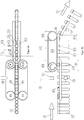
- FIG. 1 shows a device (1) for isolated transport and testing of preforms (2), hereinafter also referred to as preforms.
- preforms (2) have a lateral surface (2.1), an end-side mouth (2.2), a closure thread (2.3) and a support ring (2.4).
- the preforms are made by means of a in FIG. 1 Feed device, not shown, fed to an examination unit (3).
- the examination unit comprises a clamping conveyor with parallel opposite sections (4.1, 4.2) of in each case by two wheels (4.3, 4.4) rotating clamping conveyor belts (4.5, 4.6).
- the wheels (4.4) are each connected to a drive, not shown (see. FIG. 2a ).
- the distance between the parallel sections (4.1, 4.2) of the clamping conveyors is determined such that the preforms (2) on the lateral surface (2.1) directly below the support ring (2.4) laterally between the clamping conveyor belts (4.5, 4.6) clamped and in the transport direction ( 5) are transported by an inlet arranged separating device (6) in the direction of an end portion (4.7) of the clamping conveyor (4) (see. FIG. 2b ).
- the separating device (6) has the effect that the preforms (2) are transported at uniform spacing without touching the lateral surface (2.1) in the transport direction (5) by means of the clamping conveyor (4).
- the support ring (2.4) of each preform (2) lying on the revolving belts (4.5, 4.6) ensures that all preforms fed in the same orientation have a matching position.
- the preforms (2) arrive one after the other in the field of view of a first and second digital camera (7.1, 7.2).
- Digital camera (7.1) looks from the top of the mouth (2.2) and the support ring (2.4) of each preform (2) and digital camera (7.2) from the side of the lateral surface (2.1).
- the images taken by the digital camera (7.1) contain image information representing a first test criterion, such as the diameter of the mouth.
- the images taken by the second digital camera (7.2) contain image information representing a second test criterion, for example information about the surface condition of the lateral surface.
- Both digital cameras (7.1, 7.2) are connected to a data processing unit (8), which depends on an evaluation of the two test criteria representing image information control commands generated.
- a screening device (9) In the transport direction (5) behind the examination unit (4), a screening device (9) is arranged which takes over the preforms (2) originating from the examination unit (3).
- the screening device (9) has a double-track vacuum conveyor belt (10) which holds the preforms (2) with their mouth (2.2) on the two mutually parallel bands (10.1, 10.2) of the vacuum conveyor belt (10) by the prevailing negative pressure.
- the distance between the belts (10.1, 10.2) of the vacuum conveyor belt (10) is determined such that the mouth (2.2) of each preform (2) bears partially against one and partly against the other of the two belts (10.1, 10.2), such as this in particular FIG. 2a is recognizable.
- a vacuum generating device (10.4) is arranged with a suction opening (10.3) for generating a partial vacuum, which via the suction opening (10.3) in the preforms (2 ) is brought into effect.
- the suction opening (10.3) opens into the space between the spaced bands (10.1, 10.2).
- the flat surface of the negative pressure generating device (10.4) on both sides of the suction opening (10.3) at the same time forms the support for the circulating belts (10.2, 10.2) of the vacuum conveyor belt (10).
- each Removal device (11.1, 11.2) can be individually activated via a controller (11.3, 11.4). If the detachment devices (11.1, 11.2) are, for example, temporary nozzles which can be acted upon by compressed air, the controls (11.3, 11.4) can be configured as electrically controllable valves for the compressed air.
- the controls (11.3, 11.4) are connected to the data processing unit (8), which activates the detachment devices (11.1, 11.2) depending on the control commands.
- each preform (2) in the vertical direction performs only a slight and coincident positional change by the negative pressure acting in the region of the vacuum belt conveyor (10).
- a discharge conveyor (12) is arranged, the preforms (2) originating from the screening device (9), unless they previously by means of the removal devices (11.1, 11.2) from the vacuum belt conveyor (10). replaced.
- the outlet conveyor device (12) has two guide rails (13.1, 13.2) arranged parallel to one another at a parallel spacing, an initial section (12.1) of the outlet conveyor device (12) being below one Endabêtes (10.6) of the vacuum conveyor belt (10) is arranged so that the support ring (2.4) of each preform (2) on the parallel guide rails (13.1, 13.2) comes into abutment.
- a position tracking system (14) is also arranged on the clamping conveyor (4) for controlling the position of each preform (2) with respect to the digital cameras (7.1, 7.2) and the detachment devices (11.1, 11.2) determine.
- the position tracking system has a trigger sensor (14.1).
- the trigger sensor (14.1) for example a photocell interruptible by each preform (2), triggers the taking of an image of each preform (2) at a time when the preform (2) is within the field of view of the two digital cameras (7.1, 7.2)
- the position tracking system (14) has a displacement sensor (14.2) which detects the position of the preform (2) after a triggered capture with respect to the trigger sensor (14.1).
Landscapes
- Engineering & Computer Science (AREA)
- Manufacturing & Machinery (AREA)
- Mechanical Engineering (AREA)
- Blow-Moulding Or Thermoforming Of Plastics Or The Like (AREA)
Abstract
Description
- Die Erfindung betrifft eine Vorrichtung zum vereinzelten Transport und Prüfen mindestens eines Prüfkriteriums von Vorformlingen während des Transports in einer Transportrichtung gemäß dem Oberbegriff des Anspruchs 1.
- Insbesondere betrifft die Erfindung eine Vorrichtung und ein Verfahren zur Massenprüfung von geometrisch übereinstimmenden Vorformlingen, sogenannten Preforms, zur Herstellung von Getränkeflaschen aus Polyethylenterephthalat (PET).
- Bei der Herstellung von Behältern aus Kunststoff, insbesondere von Getränkeflaschen, werden zunächst Vorformlinge einschließlich ihres Verschlussgewindes im Spritzguss hergestellt. Anschließend werden die Vorformlinge zu fertigen Behältern weiterverarbeitet. Der Vorformling wird hierzu erwärmt, in ein Formwerkzeug eingespannt, auf die endgültige Länge gestreckt und anschließend mit Druckluft in die endgültige Form gebracht. Nach dem Abkühlen wird das Formwerkzeug geöffnet und der fertige Behälter ausgeworfen.
- Fehlerhafte Vorformlinge verursachen Produktionsausfälle sowie zusätzliche Material-, Energie- und Herstellungskosten. Es wird daher angestrebt, dass die zur Behälterherstellung verwendeten Vorformlinge nahezu fehlerfrei sind. Typische Fehler sind Dimensionsfehler, Materialfehlstellen sowie Farbfehler. Dimensionsfehler können sich auf die Länge, Form und den Durchmesser der Vorformlinge beziehen. Materialfehlstellen können sich beispielsweise aus einer fehlerhafte Länge des Anspritzpunktes, unvollständig geschmolzenem Material, Blasen, Ölspritzern sowie Verunreinigungen ergeben. Farbfehler umfassen Farb- und Intensitätsabweichungen sowie fehlerhafte Mengen an UV-Blockern.
- Aus dem Stand der Technik sind Vorrichtungen und Verfahren zur Prüfung und Aussortierung von Vorformlingen bekannt, die die Vorformlinge im kontinuierlichen Durchlauf auf mechanische und optische Fehler überprüfen und fehlerhafte Vorformlinge aussortieren.
- Aus der
EP 3 263 235 A1 ist ein Verfahren und eine gattungsgemäße Vorrichtung zum Transport und zur Untersuchung von schnelllaufenden Behandlungsgütern bekannt, die eine Untersuchungseinheit und eine Aussonderungsvorrichtung aufweist. Bei den Behandlungsgütern handelt es sich beispielsweise um Preforms für Blasformverfahren oder andere zylindrische, einseitig geschlossene Hohlkörper. Die Untersuchungseinheit, weist mindestens eine Kontrollkamera, eine mit dieser verbundene Steuereinheit sowie einen Klemmförderer auf. Der Klemmförderer verfügt über zwei, um je ein Antriebsrad und ein weiteres Rad umlaufende vorgespannte Bänder, die zwischen sich einen Förderweg definieren und die vereinzelten, sich nicht berührenden Hohlkörper in übereinstimmender Orientierung an der mindestens einen Kontrollkamera entlang des Transportwegs vorbei transportieren. Die Kontrollkamera blickt von oben auf die Stirnseite jedes Hohlkörpers und ist mit der Steuereinheit verbunden. Die Steuereinheit erhält Daten der Kontrollkamera, nämlich die Bilddaten der einzelnen Hohlkörper und vergleicht diese mit Sollwerten. Am Ende des Transportweges der Untersuchungseinheit ist die Aussonderungsvorrichtung so angeordnet, dass sie auf die Hohlkörper einwirken kann, die die Untersuchungseinheit verlassen haben. Die Aussonderungsvorrichtung wirft die Hohlkörper annähernd im freien Wurf aus, wobei die Aussonderungsvorrichtung die Flugbahnen von als fehlerhaft erkannten Hohlkörpern und von als fehlerfrei erkannten Hohlkörpern relativ zueinander mittels einer berührungslosen Kraftausübung ändert. Die Aussonderungsvorrichtung weist zu diesem Zweck eine ventilgesteuerte Düse auf, deren Düsenöffnung auf die Flugbahn der Hohlkörper gerichtet ist. Hat die Steuereinheit anhand der Bilddaten der Kontrollkamera einen Hohlkörper als fehlerbehaftet erkannt, schickt sie ein Steuersignal an das Ventil und öffnet die Düse zu einem Zeitpunkt, der so gewählt ist, dass ein aus der Düse austretender Druckluftstoß auf den Hohlkörper trifft, wenn dieser den Wirkbereich der Düse der Aussonderungsvorrichtung eintritt. Die Flugbahn eines fehlerbehafteten Hohlkörpers unterscheidet sich damit von der Flugbahn eines als fehlerfrei erkannten Hohlkörpers, sodass fehlerfreie von fehlerbehafteten Körpern getrennt werden können. - Ein Nachteil der bekannten Vorrichtung besteht darin, dass die Instabilität der Hohlkörper während des Fluges zu Fehlsortierungen führen können. Die Trennung der fehlerbehafteten von den fehlerfreien Hohlkörper durch eine Veränderung ihrer Flugbahn hat darüber hinaus zur Folge, dass die bei Zufuhr der Hohlkörper zu der Untersuchungseinheit übereinstimmende Orientierung der Hohlkörper und die Informationen über deren sequentielle Ordnung vollständig verloren gehen. Eine automatisierte Weiterverarbeitung der sortierten Hohlkörper ist daher mit hohem Aufwand verbunden. Schließlich ist die bekannte Vorrichtung lediglich zur Trennung von fehlerbehafteten und fehlerfreien Hohlkörpern geeignet.
- Die
EP 2 112 502 A1 offenbart ein weiteres Verfahren und eine Vorrichtung zur Prüfung und Aussortierung von Preforms, wobei die Preforms im Durchlauf auf mechanische und optische Defekte überprüft und defekte Preforms ausgeschieden werden. Die Vorrichtung umfasst einen Behälter für angelieferte Preforms, eine Greifeinrichtung zur Aufnahme von Preforms aus dem Behälter und deren Ausrichtung mit der Mündung nach oben, einen Riemenförderer zur Stabilisierung der Preforms und eine optische Untersuchungseinheit mit einer Vorrichtung zur Aussonderung unbrauchbarer Preforms. Die optische Untersuchnungseinheit weist eine Vakuumfördereinrichtung mit einem rückseitig mit Vakuum beaufschlagten perforierten Vakuumförderband sowie verschiedene Kameras und eine Bildverarbeitung auf. Die Aussonderungsvorrichtung hebt das Haltevakuum der als fehlerhaft erkannten Preforms auf. Ferner weist die Vorrichtung einen Behälter für unbrauchbare Preforms und einem Behälter für geprüfte und als einwandfrei befundene Preforms auf. Der Riemenförderer übergibt die in senkrechter Lage stabilisierten Preforms nacheinander an die Vakuumfördereinrichtung der optischen Untersuchnungseinheit, welche die Preforms an ihrer Mündung und ausschließlich durch Vakuum gehalten transportiert. Die optische Untersuchnungseinheit weist drei Kameras auf, welche jeweils in einem Winkel von 120° in der Bildebene versetzt angeordnet sind und eine Kamera, die jeden Preform von unten aufnimmt. Die Kameras der optischen Untersuchnungseinheit ermöglichen eine vollständige Abbildung der äußeren Oberfläche der Preforms, nicht jedoch des an dem Vakuumförderband anliegenden Mündungsbereichs. Zudem geht auch in dieser Prüfvorrichtung die Information über die sequentielle Ordnung der geprüften und als einwandfrei befundenen Preforms verloren. - Ausgehend von der
EP 3 263 235 A1 als nächstliegendem Stand der Technik liegt der Erfindung die Aufgabe zugrunde, eine gattungsgemäße Vorrichtung zu schaffen, bei der Fehlsortierungen vermieden werden und die Orientierung von Preforms mit bestimmten detektierten Prüfkriterien sowie deren sequentielle Ordnung beibehalten wird. In einer vorteilhaften Ausgestaltung der Erfindung soll mit der Vorrichtung eine Trennung der Vorformlinge nach mehr als zwei Prüfungskriterien ermöglicht werden. - Diese Aufgabe wird durch eine Vorrichtung mit den Merkmalen des Anspruchs 1 gelöst.
- Die Nutzung eines Klemmförderbandes in der Untersuchungseinheit gewährleistet, dass die für die Prüfung relevanten Bereiche jedes Vorformlings nicht durch Komponenten des Förderers verdeckt werden. Insbesondere erlaubt die Nutzung des Klemmförderbandes in der Untersuchungseinheit eine Anordnung von Digitalkameras, welche nicht nur eine vorzugsweise vollständige Abbildung der äußeren Oberfläche der Preforms, sondern auch des Mündungsbereichs ermöglichen. Des Weiteren wird durch den Klemmförderer, der die Vorformlinge mündungsnah einklemmt, ein für die Aufnahmen der Bilder ungünstiges Schwingen weitgehend ausgeschlossen.
- Die Aussonderungsvorrichtung weist erfindungsgemäß ein Vakuumförderband auf, das die Preforms mit ihrer Mündung an dem Vakuumförderband durch den herrschenden Unterdruck hält. Die Preforms halten daher auch in der Aussonderungsvorrichtung die vorgegebene Orientierung und Lage bei. Um die Preforms ohne Änderung der Lage und Orientierung kontrolliert an die Aussonderungsvorrichtung zu übergeben, ist in Transportrichtung ein Anfangsabschnitt des Vakuumförderbandes oberhalb eines Endabschnitts des Klemmförderers in einem Abstand angeordnet, dass die nach oben weisenden Mündungen jedes Preforms an dem Vakuumförderband in dem Überlappungsbereich der beiden Förderer zur Anlage gelangen. Die durch den Klemmförderer und das Vakuumförderband definierten Transportebenen sind parallel zueinander. Sämtliche Mündungen der in gleicher Lage und Orientierung von dem Klemmförderer geförderten Preforms liegen in geringem Abstand unter der durch das Vakuumförderband definierten Transportebene, so dass die Preforms von dem herrschenden Unterdruck angesaugt und von dem Vakuumförderband übernommen werden.
- Die Aussonderungsvorrichtung verfügt außerdem über mindestens eine von einer Steuerung aktivierbare Ablöseeinrichtung, die zum Ablösen einzelner Preforms von dem Vakuumförderband eingerichtet ist. Werden von der Datenverarbeitungseinheit abhängig von der Auswertung der das mindestens eine Prüfkriterium repräsentierenden Bildinformationen beispielsweise einzelne Preforms als fehlerhaft erkannt, wird die Steuerung der Ablöseeinrichtung aktiviert und löst gezielt den fehlerhaften Vorformling von dem Vakuumförderband ab. Die fehlerfreien Vorformlinge werden indes unter Beibehaltung ihrer Orientierung und sequentiellen Ordnung durch das Vakuumförderband weiter transportiert. In Transportrichtung hinter der Aussonderungsvorrichtung ist eine Auslauftransporteinrichtung angeordnet, die die von der Aussonderungsvorrichtung stammenden Vorformlinge übernimmt, beispielsweise die als fehlerfrei erkannten Vorformlinge. Die Auslauftransportvorrichtung weist hierzu zwei in parallelem Abstand angeordnete Führungsschienen auf, wobei in Transportrichtung ein Anfangsabschnitt der Auslauftransporteinrichtung unterhalb eines Endabschnitts des Vakuumförderbandes angeordnet ist, sodass der Tragring jedes Vorformlings spätestens mit dem Ablösen des Vorformlings am Ende des Vakuumförderbandes auf den Führungsschienen zur Anlage gelangt. Auf einen Antrieb für den Weitertransport der mit dem Tragring auf den Führungsschienen aufliegenden Vorformling kann verzichtet werden, wenn die Führungsschienen ausgehend von dem Endabschnitt des Vakuumbandes nach unten geneigt sind, um den Weitertransport der Vorformlinge aufgrund der Schwerkraft zu bewirken. Alternativ kann jedoch auch ein gesonderter Antrieb zum Weitertransport der in den Führungsschienen befindlichen Vorformlinge vorgesehen sein, beispielsweise ein Druckluftantrieb.
- Erfindungsgemäß behalten die der Auslauftransporteinrichtung zugeführten Vorformlinge ihre Orientierung und Lage sowie sequentielle Ordnung bei und können daher mit geringem Aufwand einer automatischen Weiterverarbeitung zugeführt werden, ohne dass eine erneute Ausrichtung erforderlich ist. Die Erfindung beruht insoweit auf der Erkenntnis, dass eine Fortsetzung der in der Untersuchnungseinheit formschlüssigen seitlichen Führung der Preforms mittels der Klemmförderbänder in der Auslauftransportvorrichtung mittels der Führungsschienen möglich ist, obwohl in der dazwischen angeordneten Aussonderungsvorrichtung zeitweilig die formschlüssige seitliche Führung der Preforms aufgegeben wird. Überraschend hat sich gezeigt, dass die zeitweilige Aufhebung der formschlüssigen seitlichen Führung der an dem Vakuumförderband hängenden Preforms in der Aussonderungsvorrichtung nicht zu Problemen beim Einlauf in die Auslauftransportvorrichtung führt, wie beispielsweise ein Ablösen von als einwandfrei befundenen Preforms beim Einlauf in die Führungsschienen und/oder ein unvollständiges Einsortieren. Mit der Sequenz aus Riemenbandförderer mit formschlüssiger seitlicher Führung, Vakuumbandförderer ausschließlich mit Reibschluss und Führungsschienentransport mit formschlüssiger seitlicher Führung kann die Orientierung von Preforms mit bestimmten detektierten Prüfkriterien sowie deren sequentielle Ordnung in der Transport- und Prüfvorrichtung beibehalten und zugleich eine vollständige Abbildung jedes Preforms einschließlich des Mündungsbereichs in der Untersuchungseinheit gewährleistet werden .
- Vorzugsweise weist die Auslauftransportvorrichtung in dem Anfangsabschnitt in Richtung der im parallelen Abstand angeordneten Führungsschienen aufeinander zulaufende Führungen auf, die den störungsfreien Einlauf der Vorformlinge zwischen den Führungsschienen unterstützen. Die Führungen können als Verlängerungen der Führungsschienen ausgeführt sein.
- Das Vakuumförderband, auch als Überkopfförderer bezeichnet, umfasst üblicherweise mindestens ein umlaufendes Förderband mit gummielastischer Oberfläche die entlang einer Mittellinie perforiert ist. Auf der Rückseite des perforierten Förderbandes liegt ein partielles Vakuum an, welches jeden Vorformling nach unten hängend hält und in Transportrichtung weiter bewegt. Alternativ weist das Vakuumförderband zwei parallel zu einander verlaufende Bänder auf, wobei der Abstand zwischen den Bändern derart bestimmt ist, dass die Mündung jedes zu prüfenden Preforms teilweise an dem einen und teilweise an dem anderen der beiden Bänder anliegt. Eine sich in Transportrichtung erstreckende Unterdruckerzeugungseinrichtung zur Erzeugung des partiellen Vakuums wird durch den Zwischenraum zwischen den beabstandeten Bändern in den Vorformlingen zur Wirkung gebracht.
- In einer vorteilhaften Ausgestaltung der Erfindung weist die Aussonderungsvorrichtung mindestens zwei unabhängig voneinander aktivierbare Ablöseeinrichtungen auf, die entlang des Transportweges des Vakuumförderers an unterschiedlichen Positionen angeordnet sind. Die Datenverarbeitungseinheit ist in diesem Fall derart eingerichtet, dass Steuerungsbefehle für die mehreren Ablöseeinrichtungen abhängig von einer Auswertung von unterschiedlichen Prüfkriterien erzeugt werden. Die erfindungsgemäße Vorrichtung ist damit in der Lage, nicht nur fehlerhafte von fehlerfreien Vorformlingen zu unterscheiden, sondern Vorformlinge abhängig von Bildinformationen, die unterschiedliche Fehler und/oder Eigenschaften des Preforms repräsentieren, an unterschiedlichen Positionen des Vakuumförderbands gezielt von dem Band abzulösen. An der in Transportrichtung ersten Ablöseeinrichtung können beispielsweise sämtliche fehlerhaften Vorformlinge von dem Vakuumbandförderer gelöst und abgeworfen werden. An einer in Transportrichtung nachfolgenden Ablöseeinrichtung können sodann fehlerfreie Vorformlinge mit einer bestimmten Oberflächenbeschaffenheit oder Rückstellmuster von dem Vakuumbandförderer abgelöst und abgeworfen werden, während alle weiteren, fehlerfreien Vorformlinge unter Beibehaltung ihrer Lage und Orientierung sowie sequentiellen Ordnung in die Auslauftransporteinrichtung gelangen.
- Um unterschiedliche Prüfkriterien zu erfassen weist die Untersuchungseinheit in vorteilhafter Ausgestaltung der Erfindung mehrere Digitalkameras auf. Mindestens eine Digitalkamera ist vorzugsweise derart ausgerichtet, dass die Mündung jedes Vorformlings in deren Sichtfeld gelangt, während mindestens eine weitere Digitalkamera derart ausgerichtet ist, dass die Mantelfläche jedes Vorformlings in deren Sichtfeld gelangt. Die von oben auf die Mündung schauende Digitalkamera dient beispielsweise zur Untersuchung des Durchmessers des Vorformlings, während die auf die Seite jedes Vorformlings blickende Digitalkamera Fehler beziehungsweise eine Oberflächenbeschaffenheit der Mantelfläche abbildet.
- Die Datenverarbeitungseinheit erzeugt die Steuerungsbefehle abhängig von einer Auswertung der das mindestens eine Prüfkriterium repräsentierenden Bildinformationen. Der Steuerungsbefehl wird von der Datenverarbeitungseinheit an die Steuerung der mindestens einen Ablöseeinrichtung der Aussonderungsvorrichtung übertragen. Da die Vorformlinge zwischen dem Zeitpunkt der Aufnahme und der gegebenenfalls erforderlichen Ablösung von dem Vakuumförderband einen Transportweg zurücklegen, muss die Datenverarbeitungseinheit den Zeitpunkt zur Aktivierung der Ablöseeinrichtung unter Berücksichtigung des Transportwegs, der Reaktionszeit der Ablöseeinrichtung und der Transportgeschwindigkeit ermitteln. Um diese Ermittlung zu vereinfachen transportieren das Klemmförderband und das übernehmende Vakuumförderband die Vorformlinge vorzugsweise mit übereinstimmender und konstanter Geschwindigkeit.
- Zur gezielten Aussonderung von Vorformlingen an jeder Ablöseeinrichtung ist außerdem an dem Klemmförderband ein Positionsverfolgungssystem angeordnet, um die Position jedes Preforms in Bezug zu jeder Digitalkamera und jeder Ablöseeinrichtung zu bestimmen. Das Positionsverfolgungssystem weist vorzugsweise einen Triggersensor auf. Der Triggersensor, beispielsweise eine Lichtschranke löst die Aufnahme eines Bildes oder einer Bildserie jedes Preforms zu einem definierten Zeitpunkt aus. Der Zeitpunkt wird derart gewählt, dass die das Prüfkriterium repräsentierenden Bereiche des Vorformlings im Sichtbereich der Digitalkamera liegen. Durch Beibehaltung einer konstanten Transportgeschwindigkeit ist gewährleistet, dass die zu prüfenden Vorformlinge synchron im richtigen Moment in dem Bild erfasst werden. Zusätzlich kann das Positionsverfolgungssystem einen Wegsensor aufweisen, der die Position des Vorformlings nach einer getriggerten Aufnahme in Bezug zu dem Trigger-Sensor erfasst.
- Um die Vorformlinge berührungslos, verschleißarm und ohne das Risiko von Beschädigungen von dem Vakuumband abzulösen umfasst die Ablöseeinrichtung vorzugsweise eine zeitweilig mittels eines Gases beaufschlagbare Düse, deren Gasstrahl in oder auf den abzulösenden Vorformling ausgerichtet ist. Die zeitweilige Beaufschlagung erfolgt vorzugsweise mittels elektrisch ansteuerbarer Ventile. Vorzugsweise trifft der Gasstrahl der Ablöseeinrichtung in einem etwa rechten Winkel zur Längsachse des Vorformlings auf dessen Mantelfläche. Grundsätzlich kann die Ablösung auch mittels eines mechanischen Ausstoßers erfolgen, sofern aufgrund der Materialeigenschaften des Vorformlings eine Beschädigung von dessen Oberfläche durch den Ausstoßer nicht zu befürchten ist.
- Nachfolgend wird die Erfindung anhand der Figuren näher erläutert. Es zeigen
- Figur 1
- eine perspektivische schematische Ansicht einer erfindungsgemäßen Vorrichtung,
- Figur 2a
- eine schematische Unteransicht sowie
- Figur 2b
- eine schematische Seitenansicht der Vorrichtung nach
Figur 1 . -
Figur 1 zeigt eine Vorrichtung (1) zum vereinzelten Transport und Prüfen von Vorformlingen (2), nachfolgend auch als Preforms bezeichnet. Jeder Preform (2) weist eine Mantelfläche (2.1), eine stirnseitige Mündung (2.2), ein Verschlussgewinde (2.3) sowie einen Tragring (2.4) auf. - Die Vorformlinge werden mittels einer in
Figur 1 nicht dargestellten Zuführeinrichtung einer Untersuchungseinheit (3) zugeführt. Die Untersuchungseinheit umfasst einen Klemmförderer mit parallel gegenüberliegenden Abschnitten (4.1, 4.2) von jeweils um zwei Räder (4.3, 4.4) umlaufenden Klemmförderbändern (4.5, 4.6). Die Räder (4.4) sind jeweils mit einem nicht dargestellten Antrieb verbunden (vgl.Figur 2a ) . - Der Abstand zwischen den parallelen Abschnitten (4.1, 4.2) der Klemmförderbänder ist derart bestimmt, dass die Vorformlinge (2) an der Mantelfläche (2.1) direkt unterhalb des Tragrings (2.4) seitlich zwischen den Klemmförderbändern (4.5, 4.6) eingeklemmt und in Transportrichtung (5) von einer Eingangs angeordneten Vereinzelungsvorrichtung (6) in Richtung eines Endabschnittes (4.7) des Klemmförderers (4) transportiert werden (vgl.
Figur 2b ). Die Vereinzelungseinrichtung (6) bewirkt, dass die Vorformlinge (2) in gleichmäßigem Abstand, ohne sich an der Mantelfläche (2.1) zu berühren in Transportrichtung (5) mittels des Klemmförderers (4) transportiert werden. Der auf den umlaufene Bändern (4.5, 4.6) aufliegende Tragring (2.4) jedes Preforms (2) bewirkt, dass sämtliche in gleicher Orientierung zugeführten Preforms eine übereinstimmende Lage aufweisen. Während des Transportes der Vorformlinge (2) in Transportrichtung (5) mittels des Klemmförderers (4) gelangen die Vorformlinge (2) vereinzelt nacheinander in den Sichtbereich einer ersten und zweiten Digitalkamera (7.1, 7.2). Digitalkamera (7.1) blickt von oben auf die Mündung (2.2) und den Tragring (2.4) jedes Vorformlings (2) und Digitalkamera (7.2) von der Seite auf die Mantelfläche (2.1). Die von der Digitalkamera (7.1) aufgenommenen Bilder enthalten ein erstes Prüfkriterium repräsentierende Bildinformationen, wie beispielsweise den Durchmesser der Mündung. Die von der zweiten Digitalkamera (7.2) aufgenommenen Bilder enthalten ein zweites Prüfkriterium repräsentierenden Bildinformationen, beispielsweise Informationen zur Oberflächenbeschaffenheit der Mantelfläche. Beide Digitalkameras (7.1, 7.2) sind mit einer Datenverarbeitungseinheit (8) verbunden, die abhängig von einer Auswertung der die beiden Prüfkriterien repräsentierenden Bildinformationen Steuerungsbefehle erzeugt. - In Transportrichtung (5) hinter der Untersuchungseinheit (4) ist eine Aussonderungsvorrichtung (9) angeordnet, die die von der Untersuchungseinheit (3) stammenden Vorformlinge (2) übernimmt. Die Aussonderungsvorrichtung (9) weist ein doppelspuriges Vakuumförderband (10) auf, das die Vorformlinge (2) mit ihrer Mündung (2.2) an den beiden parallel zueinander laufenden Bändern (10.1, 10.2) des Vakuumförderbandes (10) durch den herrschenden Unterdruck hält. Der Abstand zwischen den Bändern (10.1, 10.2) des Vakuumförderbandes (10) ist derart bestimmt, dass die Mündung (2.2) jedes Vorformlings (2) teilweise an dem einen und teilweise an dem anderen der beiden Bänder (10.1, 10.2) anliegt, wie dies insbesondere aus
Figur 2a erkennbar ist. - Zwischen dem Ober- und Untertrum der umlaufenden Bänder (10.1, 10.2) des Vakuumförderbandes (10) ist eine Unterdruckerzeugungseinrichtung (10.4) mit einer Ansaugöffnung (10.3) zur Erzeugung eines partiellen Vakuums angeordnet, das über die Ansaugöffnung (10.3) in den Vorformlingen (2) zur Wirkung gebracht wird. Die Ansaugöffnung (10.3) mündet in dem Zwischenraum zwischen den beabstandeten Bändern (10.1, 10.2). Die ebene Oberfläche der Unterdruckerzeugungseinrichtung (10.4) zu beiden Seiten der Ansaugöffnung (10.3) bildet zugleich die Auflage für die umlaufenden Bänder (10.2, 10.2) des Vakuumförderbandes (10).
- Unterhalb des Untertrums des Vakuumförderbandes sind in Transportrichtung (5) versetzt zueinander zwei Ablöseeinrichtungen (11.1, 11.2) angeordnet. Jede Ablöseeinrichtung (11.1, 11.2) ist über eine Steuerung (11.3, 11.4) einzeln aktivierbar. Handelt es sich bei den Ablöseeinrichtungen (11.1, 11.2) beispielsweise um zeitweilig mittels Druckluft beaufschlagbare Düsen, können die Steuerungen(11.3, 11.4) als elektrisch ansteuerbare Ventile für die Druckluft ausgestaltet sein. Die Steuerungen (11.3, 11.4) sind mit der Datenverarbeitungseinheit (8) verbunden, die die Ablöseeinrichtungen (11.1, 11.2) abhängig von den Steuerungsbefehlen aktiviert.
- Aus der Seitenansicht nach
Figur 2b ist erkennbar, dass ein Anfangsabschnitt (10.5) des Vakuumförderbandes (10) oberhalb des Endabschnittes (4.7) des Klemmförderers (4) in einem vertikalen Abstand angeordnet ist, der derart bemessen ist, dass die nach oben weisenden Mündungen (2.2) jedes Vorformlings (2) in dem Endabschnitt (4.7) an dem Anfangsabschnitt (10.5) des Vakuumförderbandes (10) zur Anlage gelangen. Hierbei vollzieht jeder Vorformling (2) in vertikaler Richtung lediglich eine geringfügige und übereinstimmende Lageänderung durch den zur Wirkung gelangenden Unterdruck im Bereich des Vakuumbandförderers (10) . - In Transportrichtung (5) hinter der Aussonderungsvorrichtung (9) ist eine Auslauftransporteinrichtung (12) angeordnet, die von der Aussonderungsvorrichtung (9) stammende Vorformlinge (2), soweit sie nicht zuvor mittels der Ablöseeinrichtungen (11.1, 11.2) von dem Vakuumbandförderer (10) abgelöst wurden, übernimmt. Die Auslauftransportvorrichtung (12) weist zwei in parallelem Abstand nebeneinander angeordnete Führungsschienen (13.1, 13.2) auf, wobei ein Anfangsabschnitt (12.1) der Auslauftransporteinrichtung (12) unterhalb eines Endabschnittes (10.6) des Vakuumförderbandes (10) angeordnet ist, sodass der Tragring (2.4) jedes Vorformlings (2) auf den parallelen Führungsschienen (13.1, 13.2) zur Anlage gelangt. An den Anfangsabschnitt (12.1) schließt sich ein nach unten geneigter Abschnitt (12.2) der Führungsschienen (13.1, 13.2) an, der in den Zeichnungen nur schematisch und nicht in voller Länge dargestellt ist. Aufgrund der Hangabtriebskräfte gleiten die an die Auslauftransporteinrichtung (12) übergebenen Vorformlinge (2) in Transportrichtung (5) weiter und können einem nachgelagerten Verarbeitungsprozess unmittelbar zugeführt werden, ohne dass sich deren Orientierung und sequentielle Ordnung aufgrund des Prüf- und Aussortiervorgangs in der erfindungsgemäßen Vorrichtung (1) zum Transport und Prüfen der Vorformlinge geändert hat.
- Zur gezielten Aussonderung von Vorformlingen an jeder Ablöseeinrichtung ist außerdem an dem Klemmförderer (4) ein Positionsverfolgungssystem (14) angeordnet, um die Position jedes Preforms (2) in Bezug zu den Digitalkameras (7.1, 7.2) und den Ablöseeinrichtungen (11.1, 11.2) zu bestimmen. Das Positionsverfolgungssystem weist einen Triggersensor (14.1) auf. Der Triggersensor (14.1), beispielsweise eine durch jeden Preform (2) unterbrechbare Lichtschranke, löst die Aufnahme eines Bildes jedes Preforms (2) zu einem Zeitpunkt aus, wenn sich der Preform (2) im Sichtbereich der beiden Digitalkameras (7.1, 7.2) befindet. Zusätzlich weist das Positionsverfolgungssystem (14) einen Wegsensor (14.2) auf, der die Position des Preforms (2) nach einer getriggerten Aufnahme in Bezug zu dem Trigger-Sensor (14.1) erfasst.
Nr. Bezeichnung 1. Vorrichtung 2. Vorformling (Preform) 2.1 Mantelfläche 2.2 Mündung 2.3 Verschlussgewinde 2.4 Tragring 3. Untersuchungseinheit 4 . Klemmförderer 4.1 Parallele Abschnitte 4.2 Parallele Abschnitte 4.3 Räder 4.4 Räder 4.5 Klemmförderbänder 4.6 Klemmförderbänder 4.7 Endabschnitt 5. Transportrichtung 6. Vereinzelungsvorrichtung 7.1 Digitalkamera 7.2 Digitalkamera 8 . Datenverarbeitungseinheit 9. Aussonderungsvorrichtung 10. Vakuumförderband 10.1 Band 10.2 Band 10.3 Ansaugöffnung 10.4 Unterdruckerzeugungseinrichtung 10.5 Anfangsabschnitt 10.6 Endabschnitt 11.1 Ablöseeinrichtung 11.2 Ablöseeinrichtung 11.3 Steuerung 11.4 Steuerung 12 Auslauftransporteinrichtung 12.1 Anfangsabschnitt 12.2 Geneigter Abschnitt 13.1 Führungsschiene 13.2 Führungsschiene 14. Positionsverfolgungssystem 14.1 Triggersensor 14.2 Wegsensor
Claims (11)
- Vorrichtung (1) zum vereinzelten Transport und Prüfen mindestens eines Prüfkriteriums von Vorformlingen (2) während des Transports in einer Transportrichtung (5), umfassend- eine Untersuchungseinheit (3), die mindestens eine Digitalkamera (7.1, 7.2), eine mit jeder Digitalkamera (7.1, 7.2) verbundene Datenverarbeitungseinheit (8) sowie einen Klemmförderer (4) aufweist, wobei- die mindestens eine Digitalkamera (7.1, 7.2) derart ausgerichtet ist, dass ein zu prüfender Vorformling (2) während des Transports mittels des Klemmförderers (4) ganz oder teilweise in deren Sichtfeld gelangt und jedes von der Digitalkamera (7.1, /.2) aufgenommene Bild das mindestens eine Prüfkriterium repräsentierende Bildinformationen enthält,- die Datenverarbeitungseinheit (8) eingerichtet ist, um abhängig von einer Auswertung der das mindestens eine Prüfkriterium repräsentierenden Bildinformationen Steuerungsbefehle zu erzeugen,- parallel gegenüberliegende Abschnitte (4.1, 4.2) von angetriebenen Klemmförderbändern (4.5, 4.6) des Klemmförderers (4) die Vorformlinge (2) mit der Mündung (2.2) nach oben weisend und in übereinstimmender Lage seitlich einklemmen,- eine Aussonderungsvorrichtung (9), die in Transportrichtung (5) hinter der Untersuchungseinheit (3) angeordnet ist und die von der Untersuchungseinheit (3) stammenden Vorformlinge (2) übernimmt,
dadurch gekennzeichnet, dass- die Vorformlinge (2) eine Mantelfläche (2.1), eine stirnseitige Mündung (2.2), ein Verschlussgewinde (2.3) sowie einen Tragring (2.4) aufweisen,- die Aussonderungsvorrichtung (9) ein Vakuumförderband (10) aufweist, eingerichtet um die Vorformlinge (2) mit ihrer Mündung (2.2) an dem Vakuumförderband (10) durch den herrschenden Unterdruck zu halten, wobei in Transportrichtung (5) ein Anfangsabschnitt (10.5) des Vakuumförderbandes (10) oberhalb eines Endabschnitts (4.7) des Klemmförderers (4) in einem Abstand angeordnet ist, so dass die nach oben weisenden Mündungen (2.2) jedes Vorformlings (2) an dem Vakuumförderband (10) zur Anlage gelangen,- die Aussonderungsvorrichtung (9) mindestens eine von einer Steuerung (11.3, 11.4) aktivierbare Ablöseeinrichtung (11.1, 11.2) aufweist, die zum Ablösen einzelner Vorformlinge (2) von dem Vakuumförderband (10) eingerichtet ist, wobei jede Steuerung (11.3, 11.4) mit der Datenverarbeitungseinheit (8) verbunden ist und die Ablöseeinrichtung (11.1, 11.2) abhängig von den Steuerungsbefehlen der Datenverarbeitungseinheit (8) aktiviert und- in Transportrichtung (5) hinter der Aussonderungsvorrichtung (9) eine Auslauftransporteinrichtung (12) angeordnet ist, die die von der Aussonderungsvorrichtung (9) stammenden Vorformlinge übernimmt, wobei- die Auslauftransporteinrichtung (12) zwei in parallelem Anstand angeordnete Führungsschienen (13.1, 13.2) aufweist und- in Transportrichtung (5) ein Anfangsabschnitt(12.1) der Auslauftransporteinrichtung (12) unterhalb eines Endabschnitts (10.6) des Vakuumförderbands (10) angeordnet ist, so dass der Tragring (2.4) jedes Vorformlings (2) auf den Führungsschienen (13.1, 13.2) zur Anlage gelangt. - Vorrichtung nach Anspruch 1, dadurch gekennzeichnet, dass das Vakuumförderband (10) zwei parallel zueinander verlaufende umlaufende Bänder (10.1, 10.2) aufweist, wobei der Abstand zwischen den Bändern (10.1, 10.2) derart bestimmt ist, dass die Mündung (2.2) jedes Vorformlings (2) teilweise an dem einen und teilweise an dem anderen der beiden Bänder (10.1, 10.2) im Untertrum anliegt.
- Vorrichtung nach Anspruch 1 oder 2, dadurch gekennzeichnet, dass die Aussonderungsvorrichtung (9) mindestens zwei unabhängig voneinander aktivierbare Ablöseeinrichtungen (11.1, 11.2) aufweist, die entlang des Transportwegs des Vakuumförderbandes (10) an unterschiedlichen Positionen angeordnet sind.
- Vorrichtung nach Anspruch 3, dadurch gekennzeichnet, dass die Datenverarbeitungseinheit (8) derart eingerichet ist, Steuerungsbefehle für die mehreren Ablöseeinrichtungen (11.1, 11.2) abhängig von einer Auswertung von unterschiedlichen Prüfkriterien zu erzeugen.
- Vorrichtung nach einem der Ansprüche 1 bis 4, dadurch gekennzeichnet, dass die mindestens eine Digitalkamera (7.1, 7.2) derart ausgerichtet ist, dass die Mündung (2.2) jedes Vorformlings (2) und/oder dessen Mantelfläche (2.1) in deren Sichtfeld gelangt.
- Vorrichtung nach einem der Ansprüche 1 bis 5, dadurch gekennzeichnet, dass der Klemmförderer (4) und das Vakuumförderband (10) die Vorformlinge (2) mit übereinstimmender Geschwindigkeit transportieren.
- Vorrichtung nach einem der Ansprüche 1 bis 6, dadurch gekennzeichnet, dass an dem Klemmförder (4) ein Positionsverfolgungssystem (14) angeordnet ist, eingerichet um die Position jedes Vorformlinge (2) in Bezug zu jeder Digitalkamera (7.1, 7.2) und jeder Ablöseeinrichtung (11.1, 11.2) zu bestimmen.
- Vorrichtung nach Anspruch 7, dadurch gekennzeichnet, dass das Positionsverfolgungssystem (14) einen Triggersensor (14.1) für eine getriggerte Aufnahme des Bildes eines Vorformlings (2) mittels der mindestens einen Digitalkamera (7.1, 7.2) aufweist.
- Vorrichtung nach Anspruch 7, dadurch gekennzeichnet, dass das Positionsverfolgungssystem (14) einen Wegsensor (14.2) aufweist.
- Vorrichtung nach einem der Ansprüche 1 bis 9, dadurch gekennzeichnet, dass jede Ablöseeinrichtung (11.1, 11.2) eine zeitweilig mittels eines Gases beaufschlagbare Düse umfasst, deren Gasstrahl in oder auf einen abzulösenden Vorformling (2) ausgerichtet ist.
- Vorrichtung nach einem der Ansprüche 1 bis 10, dadurch gekennzeichnet, dass die Auslauftransportvorrichtung (12) in dem Anfangsabschnitt (12.1) in Richtung der Führungsschienen (13.1, 13.2) aufeinander zulaufende Führungen aufweist.
Applications Claiming Priority (1)
| Application Number | Priority Date | Filing Date | Title |
|---|---|---|---|
| DE102018110803.6A DE102018110803A1 (de) | 2018-05-04 | 2018-05-04 | Vorrichtung zum Transport und Prüfen von Vorformlingen |
Publications (2)
| Publication Number | Publication Date |
|---|---|
| EP3564006A1 true EP3564006A1 (de) | 2019-11-06 |
| EP3564006B1 EP3564006B1 (de) | 2020-10-14 |
Family
ID=66290273
Family Applications (1)
| Application Number | Title | Priority Date | Filing Date |
|---|---|---|---|
| EP19171304.9A Active EP3564006B1 (de) | 2018-05-04 | 2019-04-26 | Vorrichtung zum transport und prüfen von vorformlingen |
Country Status (2)
| Country | Link |
|---|---|
| EP (1) | EP3564006B1 (de) |
| DE (1) | DE102018110803A1 (de) |
Cited By (3)
| Publication number | Priority date | Publication date | Assignee | Title |
|---|---|---|---|---|
| CN113210277A (zh) * | 2021-06-09 | 2021-08-06 | 昆山广辉精密五金有限公司 | 一种适用于电感线圈的不良品分拣设备 |
| US20240009916A1 (en) * | 2020-12-22 | 2024-01-11 | Sidel Participations | Method for automatically verifying the presence of members for holding preforms in a heating station |
| CN117686826A (zh) * | 2024-01-31 | 2024-03-12 | 四川辰宇微视科技有限公司 | 一种融合相机的紫外镜头电性能检测装置及方法 |
Families Citing this family (7)
| Publication number | Priority date | Publication date | Assignee | Title |
|---|---|---|---|---|
| CH718562A1 (de) * | 2021-04-23 | 2022-10-31 | M Tanner Ag | Zulaufvorrichtung für eine Förderanlage für Vorformlinge. |
| IT202100030506A1 (it) * | 2021-12-02 | 2023-06-02 | Sacmi Imola Sc | Dispositivo di presa per il supporto e la movimentazione di preforme. |
| JP2023082680A (ja) * | 2021-12-02 | 2023-06-14 | サクミ・イモラ・ソシエタ・コーペラティバ | 容器をブロー成形するための機器 |
| DE102022111523A1 (de) | 2022-05-09 | 2023-11-09 | Krones Aktiengesellschaft | Verfahren und Vorrichtung zur Herstellung von Kunststoffbehältnissen mit zonenweiser Inspektion von Kunststoffvorformlingen |
| DE102024101047A1 (de) | 2024-01-15 | 2025-07-17 | Krones Aktiengesellschaft | Vorrichtung und Verfahren zum Behandeln von Kunststoffvorformlingen |
| DE102024103090A1 (de) * | 2024-02-05 | 2025-08-07 | Khs Gmbh | Transportanordnung, Blasmaschinenanordnung sowie Verfahren zum Transport von Behältern |
| DE102024116868A1 (de) * | 2024-06-14 | 2025-12-18 | Khs Gmbh | Transportanordnung, Blasmaschinenanordnung sowie Verfahren zum Transport von Vorformlingen |
Citations (4)
| Publication number | Priority date | Publication date | Assignee | Title |
|---|---|---|---|---|
| DE19821105A1 (de) * | 1998-05-12 | 1999-11-18 | Krones Ag | Vorrichtung und Verfahren zur Herstellung von Kunststoffhohlkörpern |
| EP2112502A1 (de) * | 2008-04-23 | 2009-10-28 | Finatec Holding AG | Verfahren und Vorrichtung zur Prüfung von Behälter-Preforms |
| US20120007289A1 (en) * | 2010-07-07 | 2012-01-12 | Graham Packaging Company, L.P. | Method and system for thermally monitoring process for forming plastic blow-molded containers |
| US20160001328A1 (en) * | 2013-03-14 | 2016-01-07 | Finatec Holding Ag | Device and method for transporting and examining fast-moving objects to be treated |
Family Cites Families (16)
| Publication number | Priority date | Publication date | Assignee | Title |
|---|---|---|---|---|
| US3932042A (en) * | 1974-05-20 | 1976-01-13 | Barry-Wehmiller Company | Container inspection apparatus and method of inspection |
| JPS54126263A (en) | 1978-03-24 | 1979-10-01 | Mitsubishi Rayon Co Ltd | Continous manufacturing of synthetic resin plate |
| JP3104151B2 (ja) * | 1993-06-08 | 2000-10-30 | 善彦 高嶋 | カラーラインセンサカメラ使用の缶内面外面の欠陥検査方法 |
| JPH0957824A (ja) * | 1995-08-25 | 1997-03-04 | Mitsubishi Heavy Ind Ltd | パリソン搬送装置 |
| DE19737527C2 (de) | 1997-08-28 | 2002-10-24 | Krones Ag | Vorrichtung zur Herstellung von Kunststoffhohlkörpern |
| JP2000168945A (ja) | 1998-12-07 | 2000-06-20 | Kirin Techno System:Kk | プリフォーム検査用搬送装置 |
| JP2001091472A (ja) | 1999-09-22 | 2001-04-06 | Ishizuka Glass Co Ltd | Petプリフォームの検査装置 |
| JP3614326B2 (ja) | 1999-09-22 | 2005-01-26 | ヤマキューオートマチックス株式会社 | 中空成形品の検査装置 |
| IT1311712B1 (it) | 1999-10-05 | 2002-03-19 | Sipa Spa | Apparato ottico-elettronico perfezionato per il controllo automaticodi preforme |
| ES2290422T5 (es) | 2003-05-22 | 2011-04-08 | M. & G. POLYMERS U.S.A. LLC | Aparato y método para controlar la calidad de preformas que tienen cada una un cuerpo de material plástico. |
| DE102004009698A1 (de) | 2004-02-27 | 2005-09-15 | Krones Ag | Inspektionsmaschine mit einer Vorrichtung zum Transportieren von Hohlkörpern |
| JP4809168B2 (ja) | 2006-09-19 | 2011-11-09 | アサヒ飲料株式会社 | ボトル容器検査装置 |
| DE502007003998D1 (de) | 2006-11-27 | 2010-07-15 | M Tanner Ag | Fördermittel und automatische Transportstrecke für zylindrische Körper |
| GB2482473A (en) | 2010-06-29 | 2012-02-08 | Constar Internat Uk Ltd | Inspection of articles |
| DE102012102073A1 (de) | 2012-03-12 | 2013-09-12 | A20 Ag | Kontrollmodul |
| CH708561A1 (de) | 2013-09-10 | 2015-03-13 | M Tanner Ag | Inspektions- und Auswerfereinheit für Vorformlinge für Kunststoffbehälter in einer Transportstrecke. |
-
2018
- 2018-05-04 DE DE102018110803.6A patent/DE102018110803A1/de not_active Withdrawn
-
2019
- 2019-04-26 EP EP19171304.9A patent/EP3564006B1/de active Active
Patent Citations (4)
| Publication number | Priority date | Publication date | Assignee | Title |
|---|---|---|---|---|
| DE19821105A1 (de) * | 1998-05-12 | 1999-11-18 | Krones Ag | Vorrichtung und Verfahren zur Herstellung von Kunststoffhohlkörpern |
| EP2112502A1 (de) * | 2008-04-23 | 2009-10-28 | Finatec Holding AG | Verfahren und Vorrichtung zur Prüfung von Behälter-Preforms |
| US20120007289A1 (en) * | 2010-07-07 | 2012-01-12 | Graham Packaging Company, L.P. | Method and system for thermally monitoring process for forming plastic blow-molded containers |
| US20160001328A1 (en) * | 2013-03-14 | 2016-01-07 | Finatec Holding Ag | Device and method for transporting and examining fast-moving objects to be treated |
Cited By (5)
| Publication number | Priority date | Publication date | Assignee | Title |
|---|---|---|---|---|
| US20240009916A1 (en) * | 2020-12-22 | 2024-01-11 | Sidel Participations | Method for automatically verifying the presence of members for holding preforms in a heating station |
| US12434425B2 (en) * | 2020-12-22 | 2025-10-07 | Sidel Participations | Method for automatically verifying the presence of members for holding preforms in a heating station |
| CN113210277A (zh) * | 2021-06-09 | 2021-08-06 | 昆山广辉精密五金有限公司 | 一种适用于电感线圈的不良品分拣设备 |
| CN117686826A (zh) * | 2024-01-31 | 2024-03-12 | 四川辰宇微视科技有限公司 | 一种融合相机的紫外镜头电性能检测装置及方法 |
| CN117686826B (zh) * | 2024-01-31 | 2024-04-09 | 四川辰宇微视科技有限公司 | 一种融合相机的紫外镜头电性能检测装置及方法 |
Also Published As
| Publication number | Publication date |
|---|---|
| EP3564006B1 (de) | 2020-10-14 |
| DE102018110803A1 (de) | 2019-11-07 |
Similar Documents
| Publication | Publication Date | Title |
|---|---|---|
| EP3564006B1 (de) | Vorrichtung zum transport und prüfen von vorformlingen | |
| EP2509894B1 (de) | Vorrichtung zum aussortieren von falsch positionierten zylindrischen körpern in einer vereinzelungs- und fördereinrichtung | |
| EP2112502B1 (de) | Verfahren und Vorrichtung zur Prüfung von Behälter-Preforms | |
| EP2845715B1 (de) | Inspektions- und Auswerfereinheit | |
| EP3183073B1 (de) | Vorrichtung und verfahren zum transport von vorformlingen im bereich einer blasmaschine | |
| EP3263235B1 (de) | Vorrichtung und verfahren zum transport und zur untersuchung von schnelllaufenden behandlungsgütern | |
| EP2295157B1 (de) | Vorrichtung und Verfahren zum Kontrollieren von Gefäßverschlüssen | |
| EP2861403B1 (de) | Vereinzelungsvorrichtung für vorformlinge mit einer einrichtung zum aussondern von falsch positionierten vorformlingen | |
| EP0996531B1 (de) | Vorrichtung und verfahren zur herstellung von kunststoffhohlkörpern | |
| DE102017123888B3 (de) | Vorrichtung und Verfahren zum Prüfen von Hohlkörpern | |
| DE102014012528A1 (de) | Vorrichtung und Verfahren zum Transport von Vorformlingen im Bereich einer Blasmaschine | |
| DE102005060814B4 (de) | Vorrichtung und Verfahren zum Formblasen von Behältern | |
| DE19737527C2 (de) | Vorrichtung zur Herstellung von Kunststoffhohlkörpern | |
| EP3954529A1 (de) | Vorrichtung und verfahren zum behandeln von kunststoffvorformlingen mit inspektionseinrichtung | |
| DE202019106352U1 (de) | Sternradeinheit | |
| EP4194110B1 (de) | Verfahren zum entfernen eines stückgutes von einem fördermittel, abblaseinrichtung und sortiersystem | |
| DE102023135939A1 (de) | Ausleitvorrichtung zum stehenden Ausleiten von Dosen, Behälterbehandlungsanlage mit einer entsprechenden Ausleitvorrichtung, Verfahren zum stehenden Ausleiten von Dosen und Verwendung einer Ausleitvorrichtung | |
| DE69804868T2 (de) | Vorrichtung zum sequentiellen transport von flaschen aus plastikmaterial | |
| DE4200546A1 (de) | Verfahren und vorrichtung zum behandeln von flaschen | |
| EP4585393A1 (de) | Vorrichtung und verfahren zum herstellen von kunststoffbehältnissen mit inspektion von kunststoffvorformlingen | |
| EP4585392A2 (de) | Vorrichtung und verfahren zum behandeln von kunststoffvorformlingen | |
| DE102023122563A1 (de) | Behältertransportvorrichtung zum Transport von Behältern | |
| DE102022114820A1 (de) | Rollensortierer DirectLink | |
| DE102024101054A1 (de) | Vorrichtung und Verfahren zum Herstellen von Kunststoffbehältnissen mit Inspektion von Kunststoffvorformlingen |
Legal Events
| Date | Code | Title | Description |
|---|---|---|---|
| PUAI | Public reference made under article 153(3) epc to a published international application that has entered the european phase |
Free format text: ORIGINAL CODE: 0009012 |
|
| STAA | Information on the status of an ep patent application or granted ep patent |
Free format text: STATUS: THE APPLICATION HAS BEEN PUBLISHED |
|
| AK | Designated contracting states |
Kind code of ref document: A1 Designated state(s): AL AT BE BG CH CY CZ DE DK EE ES FI FR GB GR HR HU IE IS IT LI LT LU LV MC MK MT NL NO PL PT RO RS SE SI SK SM TR |
|
| AX | Request for extension of the european patent |
Extension state: BA ME |
|
| STAA | Information on the status of an ep patent application or granted ep patent |
Free format text: STATUS: REQUEST FOR EXAMINATION WAS MADE |
|
| 17P | Request for examination filed |
Effective date: 20191224 |
|
| RBV | Designated contracting states (corrected) |
Designated state(s): AL AT BE BG CH CY CZ DE DK EE ES FI FR GB GR HR HU IE IS IT LI LT LU LV MC MK MT NL NO PL PT RO RS SE SI SK SM TR |
|
| GRAP | Despatch of communication of intention to grant a patent |
Free format text: ORIGINAL CODE: EPIDOSNIGR1 |
|
| STAA | Information on the status of an ep patent application or granted ep patent |
Free format text: STATUS: GRANT OF PATENT IS INTENDED |
|
| RIC1 | Information provided on ipc code assigned before grant |
Ipc: B29L 31/00 20060101ALN20200423BHEP Ipc: B29C 49/06 20060101ALN20200423BHEP Ipc: B29C 49/42 20060101AFI20200423BHEP |
|
| INTG | Intention to grant announced |
Effective date: 20200507 |
|
| GRAS | Grant fee paid |
Free format text: ORIGINAL CODE: EPIDOSNIGR3 |
|
| GRAA | (expected) grant |
Free format text: ORIGINAL CODE: 0009210 |
|
| STAA | Information on the status of an ep patent application or granted ep patent |
Free format text: STATUS: THE PATENT HAS BEEN GRANTED |
|
| AK | Designated contracting states |
Kind code of ref document: B1 Designated state(s): AL AT BE BG CH CY CZ DE DK EE ES FI FR GB GR HR HU IE IS IT LI LT LU LV MC MK MT NL NO PL PT RO RS SE SI SK SM TR |
|
| REG | Reference to a national code |
Ref country code: GB Ref legal event code: FG4D Free format text: NOT ENGLISH |
|
| REG | Reference to a national code |
Ref country code: CH Ref legal event code: EP Ref country code: AT Ref legal event code: REF Ref document number: 1323141 Country of ref document: AT Kind code of ref document: T Effective date: 20201015 |
|
| REG | Reference to a national code |
Ref country code: DE Ref legal event code: R096 Ref document number: 502019000290 Country of ref document: DE |
|
| REG | Reference to a national code |
Ref country code: CH Ref legal event code: NV Representative=s name: PATENTANWAELTE SCHAAD, BALASS, MENZL AND PARTN, CH |
|
| REG | Reference to a national code |
Ref country code: IE Ref legal event code: FG4D Free format text: LANGUAGE OF EP DOCUMENT: GERMAN |
|
| REG | Reference to a national code |
Ref country code: CH Ref legal event code: NV Representative=s name: SCHAAD, BALASS, MENZL AND PARTNER AG PATENT- U, CH |
|
| REG | Reference to a national code |
Ref country code: NL Ref legal event code: MP Effective date: 20201014 |
|
| PG25 | Lapsed in a contracting state [announced via postgrant information from national office to epo] |
Ref country code: GR Free format text: LAPSE BECAUSE OF FAILURE TO SUBMIT A TRANSLATION OF THE DESCRIPTION OR TO PAY THE FEE WITHIN THE PRESCRIBED TIME-LIMIT Effective date: 20210115 Ref country code: NO Free format text: LAPSE BECAUSE OF FAILURE TO SUBMIT A TRANSLATION OF THE DESCRIPTION OR TO PAY THE FEE WITHIN THE PRESCRIBED TIME-LIMIT Effective date: 20210114 Ref country code: FI Free format text: LAPSE BECAUSE OF FAILURE TO SUBMIT A TRANSLATION OF THE DESCRIPTION OR TO PAY THE FEE WITHIN THE PRESCRIBED TIME-LIMIT Effective date: 20201014 Ref country code: PT Free format text: LAPSE BECAUSE OF FAILURE TO SUBMIT A TRANSLATION OF THE DESCRIPTION OR TO PAY THE FEE WITHIN THE PRESCRIBED TIME-LIMIT Effective date: 20210215 Ref country code: RS Free format text: LAPSE BECAUSE OF FAILURE TO SUBMIT A TRANSLATION OF THE DESCRIPTION OR TO PAY THE FEE WITHIN THE PRESCRIBED TIME-LIMIT Effective date: 20201014 |
|
| REG | Reference to a national code |
Ref country code: LT Ref legal event code: MG4D |
|
| PG25 | Lapsed in a contracting state [announced via postgrant information from national office to epo] |
Ref country code: SE Free format text: LAPSE BECAUSE OF FAILURE TO SUBMIT A TRANSLATION OF THE DESCRIPTION OR TO PAY THE FEE WITHIN THE PRESCRIBED TIME-LIMIT Effective date: 20201014 Ref country code: IS Free format text: LAPSE BECAUSE OF FAILURE TO SUBMIT A TRANSLATION OF THE DESCRIPTION OR TO PAY THE FEE WITHIN THE PRESCRIBED TIME-LIMIT Effective date: 20210214 Ref country code: PL Free format text: LAPSE BECAUSE OF FAILURE TO SUBMIT A TRANSLATION OF THE DESCRIPTION OR TO PAY THE FEE WITHIN THE PRESCRIBED TIME-LIMIT Effective date: 20201014 Ref country code: LV Free format text: LAPSE BECAUSE OF FAILURE TO SUBMIT A TRANSLATION OF THE DESCRIPTION OR TO PAY THE FEE WITHIN THE PRESCRIBED TIME-LIMIT Effective date: 20201014 Ref country code: BG Free format text: LAPSE BECAUSE OF FAILURE TO SUBMIT A TRANSLATION OF THE DESCRIPTION OR TO PAY THE FEE WITHIN THE PRESCRIBED TIME-LIMIT Effective date: 20210114 Ref country code: ES Free format text: LAPSE BECAUSE OF FAILURE TO SUBMIT A TRANSLATION OF THE DESCRIPTION OR TO PAY THE FEE WITHIN THE PRESCRIBED TIME-LIMIT Effective date: 20201014 |
|
| PG25 | Lapsed in a contracting state [announced via postgrant information from national office to epo] |
Ref country code: NL Free format text: LAPSE BECAUSE OF FAILURE TO SUBMIT A TRANSLATION OF THE DESCRIPTION OR TO PAY THE FEE WITHIN THE PRESCRIBED TIME-LIMIT Effective date: 20201014 Ref country code: HR Free format text: LAPSE BECAUSE OF FAILURE TO SUBMIT A TRANSLATION OF THE DESCRIPTION OR TO PAY THE FEE WITHIN THE PRESCRIBED TIME-LIMIT Effective date: 20201014 |
|
| REG | Reference to a national code |
Ref country code: DE Ref legal event code: R026 Ref document number: 502019000290 Country of ref document: DE |
|
| PLBI | Opposition filed |
Free format text: ORIGINAL CODE: 0009260 |
|
| PLAX | Notice of opposition and request to file observation + time limit sent |
Free format text: ORIGINAL CODE: EPIDOSNOBS2 |
|
| PG25 | Lapsed in a contracting state [announced via postgrant information from national office to epo] |
Ref country code: CZ Free format text: LAPSE BECAUSE OF FAILURE TO SUBMIT A TRANSLATION OF THE DESCRIPTION OR TO PAY THE FEE WITHIN THE PRESCRIBED TIME-LIMIT Effective date: 20201014 Ref country code: EE Free format text: LAPSE BECAUSE OF FAILURE TO SUBMIT A TRANSLATION OF THE DESCRIPTION OR TO PAY THE FEE WITHIN THE PRESCRIBED TIME-LIMIT Effective date: 20201014 Ref country code: SK Free format text: LAPSE BECAUSE OF FAILURE TO SUBMIT A TRANSLATION OF THE DESCRIPTION OR TO PAY THE FEE WITHIN THE PRESCRIBED TIME-LIMIT Effective date: 20201014 Ref country code: SM Free format text: LAPSE BECAUSE OF FAILURE TO SUBMIT A TRANSLATION OF THE DESCRIPTION OR TO PAY THE FEE WITHIN THE PRESCRIBED TIME-LIMIT Effective date: 20201014 Ref country code: RO Free format text: LAPSE BECAUSE OF FAILURE TO SUBMIT A TRANSLATION OF THE DESCRIPTION OR TO PAY THE FEE WITHIN THE PRESCRIBED TIME-LIMIT Effective date: 20201014 Ref country code: LT Free format text: LAPSE BECAUSE OF FAILURE TO SUBMIT A TRANSLATION OF THE DESCRIPTION OR TO PAY THE FEE WITHIN THE PRESCRIBED TIME-LIMIT Effective date: 20201014 |
|
| 26 | Opposition filed |
Opponent name: KRONES AG Effective date: 20210713 |
|
| PG25 | Lapsed in a contracting state [announced via postgrant information from national office to epo] |
Ref country code: DK Free format text: LAPSE BECAUSE OF FAILURE TO SUBMIT A TRANSLATION OF THE DESCRIPTION OR TO PAY THE FEE WITHIN THE PRESCRIBED TIME-LIMIT Effective date: 20201014 |
|
| PLBB | Reply of patent proprietor to notice(s) of opposition received |
Free format text: ORIGINAL CODE: EPIDOSNOBS3 |
|
| PLBP | Opposition withdrawn |
Free format text: ORIGINAL CODE: 0009264 |
|
| PG25 | Lapsed in a contracting state [announced via postgrant information from national office to epo] |
Ref country code: AL Free format text: LAPSE BECAUSE OF FAILURE TO SUBMIT A TRANSLATION OF THE DESCRIPTION OR TO PAY THE FEE WITHIN THE PRESCRIBED TIME-LIMIT Effective date: 20201014 Ref country code: IT Free format text: LAPSE BECAUSE OF FAILURE TO SUBMIT A TRANSLATION OF THE DESCRIPTION OR TO PAY THE FEE WITHIN THE PRESCRIBED TIME-LIMIT Effective date: 20201014 |
|
| PG25 | Lapsed in a contracting state [announced via postgrant information from national office to epo] |
Ref country code: SI Free format text: LAPSE BECAUSE OF FAILURE TO SUBMIT A TRANSLATION OF THE DESCRIPTION OR TO PAY THE FEE WITHIN THE PRESCRIBED TIME-LIMIT Effective date: 20201014 Ref country code: MC Free format text: LAPSE BECAUSE OF FAILURE TO SUBMIT A TRANSLATION OF THE DESCRIPTION OR TO PAY THE FEE WITHIN THE PRESCRIBED TIME-LIMIT Effective date: 20201014 |
|
| PG25 | Lapsed in a contracting state [announced via postgrant information from national office to epo] |
Ref country code: LU Free format text: LAPSE BECAUSE OF NON-PAYMENT OF DUE FEES Effective date: 20210426 |
|
| PLAY | Examination report in opposition despatched + time limit |
Free format text: ORIGINAL CODE: EPIDOSNORE2 |
|
| REG | Reference to a national code |
Ref country code: BE Ref legal event code: MM Effective date: 20210430 |
|
| PG25 | Lapsed in a contracting state [announced via postgrant information from national office to epo] |
Ref country code: FR Free format text: LAPSE BECAUSE OF NON-PAYMENT OF DUE FEES Effective date: 20210430 |
|
| PG25 | Lapsed in a contracting state [announced via postgrant information from national office to epo] |
Ref country code: IE Free format text: LAPSE BECAUSE OF NON-PAYMENT OF DUE FEES Effective date: 20210426 |
|
| PLBC | Reply to examination report in opposition received |
Free format text: ORIGINAL CODE: EPIDOSNORE3 |
|
| PG25 | Lapsed in a contracting state [announced via postgrant information from national office to epo] |
Ref country code: IS Free format text: LAPSE BECAUSE OF FAILURE TO SUBMIT A TRANSLATION OF THE DESCRIPTION OR TO PAY THE FEE WITHIN THE PRESCRIBED TIME-LIMIT Effective date: 20210214 |
|
| PG25 | Lapsed in a contracting state [announced via postgrant information from national office to epo] |
Ref country code: BE Free format text: LAPSE BECAUSE OF NON-PAYMENT OF DUE FEES Effective date: 20210430 |
|
| PLCK | Communication despatched that opposition was rejected |
Free format text: ORIGINAL CODE: EPIDOSNREJ1 |
|
| REG | Reference to a national code |
Ref country code: DE Ref legal event code: R100 Ref document number: 502019000290 Country of ref document: DE |
|
| PLBN | Opposition rejected |
Free format text: ORIGINAL CODE: 0009273 |
|
| STAA | Information on the status of an ep patent application or granted ep patent |
Free format text: STATUS: OPPOSITION REJECTED |
|
| 27O | Opposition rejected |
Effective date: 20221015 |
|
| P01 | Opt-out of the competence of the unified patent court (upc) registered |
Effective date: 20230516 |
|
| PG25 | Lapsed in a contracting state [announced via postgrant information from national office to epo] |
Ref country code: CY Free format text: LAPSE BECAUSE OF FAILURE TO SUBMIT A TRANSLATION OF THE DESCRIPTION OR TO PAY THE FEE WITHIN THE PRESCRIBED TIME-LIMIT Effective date: 20201014 |
|
| PG25 | Lapsed in a contracting state [announced via postgrant information from national office to epo] |
Ref country code: HU Free format text: LAPSE BECAUSE OF FAILURE TO SUBMIT A TRANSLATION OF THE DESCRIPTION OR TO PAY THE FEE WITHIN THE PRESCRIBED TIME-LIMIT; INVALID AB INITIO Effective date: 20190426 |
|
| GBPC | Gb: european patent ceased through non-payment of renewal fee |
Effective date: 20230426 |
|
| PG25 | Lapsed in a contracting state [announced via postgrant information from national office to epo] |
Ref country code: GB Free format text: LAPSE BECAUSE OF NON-PAYMENT OF DUE FEES Effective date: 20230426 |
|
| PG25 | Lapsed in a contracting state [announced via postgrant information from national office to epo] |
Ref country code: GB Free format text: LAPSE BECAUSE OF NON-PAYMENT OF DUE FEES Effective date: 20230426 |
|
| PG25 | Lapsed in a contracting state [announced via postgrant information from national office to epo] |
Ref country code: MK Free format text: LAPSE BECAUSE OF FAILURE TO SUBMIT A TRANSLATION OF THE DESCRIPTION OR TO PAY THE FEE WITHIN THE PRESCRIBED TIME-LIMIT Effective date: 20201014 |
|
| PG25 | Lapsed in a contracting state [announced via postgrant information from national office to epo] |
Ref country code: MT Free format text: LAPSE BECAUSE OF FAILURE TO SUBMIT A TRANSLATION OF THE DESCRIPTION OR TO PAY THE FEE WITHIN THE PRESCRIBED TIME-LIMIT Effective date: 20201014 |
|
| REG | Reference to a national code |
Ref country code: AT Ref legal event code: MM01 Ref document number: 1323141 Country of ref document: AT Kind code of ref document: T Effective date: 20240426 |
|
| PGFP | Annual fee paid to national office [announced via postgrant information from national office to epo] |
Ref country code: DE Payment date: 20250205 Year of fee payment: 7 |
|
| PGFP | Annual fee paid to national office [announced via postgrant information from national office to epo] |
Ref country code: CH Payment date: 20250501 Year of fee payment: 7 |
|
| PG25 | Lapsed in a contracting state [announced via postgrant information from national office to epo] |
Ref country code: AT Free format text: LAPSE BECAUSE OF NON-PAYMENT OF DUE FEES Effective date: 20240426 |
|
| PG25 | Lapsed in a contracting state [announced via postgrant information from national office to epo] |
Ref country code: TR Free format text: LAPSE BECAUSE OF FAILURE TO SUBMIT A TRANSLATION OF THE DESCRIPTION OR TO PAY THE FEE WITHIN THE PRESCRIBED TIME-LIMIT Effective date: 20201014 |
|
| PGFP | Annual fee paid to national office [announced via postgrant information from national office to epo] |
Ref country code: AT Payment date: 20260410 Year of fee payment: 5 |