EP3564012A1 - Druckverfahren mit tropfziehen/extrusion - Google Patents
Druckverfahren mit tropfziehen/extrusion Download PDFInfo
- Publication number
- EP3564012A1 EP3564012A1 EP19167994.3A EP19167994A EP3564012A1 EP 3564012 A1 EP3564012 A1 EP 3564012A1 EP 19167994 A EP19167994 A EP 19167994A EP 3564012 A1 EP3564012 A1 EP 3564012A1
- Authority
- EP
- European Patent Office
- Prior art keywords
- nozzle
- substrate
- filaments
- range
- anchors
- Prior art date
- Legal status (The legal status is an assumption and is not a legal conclusion. Google has not performed a legal analysis and makes no representation as to the accuracy of the status listed.)
- Granted
Links
Images


Classifications
-
- B—PERFORMING OPERATIONS; TRANSPORTING
- B05—SPRAYING OR ATOMISING IN GENERAL; APPLYING FLUENT MATERIALS TO SURFACES, IN GENERAL
- B05D—PROCESSES FOR APPLYING FLUENT MATERIALS TO SURFACES, IN GENERAL
- B05D1/00—Processes for applying liquids or other fluent materials
- B05D1/40—Distributing applied liquids or other fluent materials by members moving relatively to surface
- B05D1/42—Distributing applied liquids or other fluent materials by members moving relatively to surface by non-rotary members
-
- B—PERFORMING OPERATIONS; TRANSPORTING
- B05—SPRAYING OR ATOMISING IN GENERAL; APPLYING FLUENT MATERIALS TO SURFACES, IN GENERAL
- B05D—PROCESSES FOR APPLYING FLUENT MATERIALS TO SURFACES, IN GENERAL
- B05D7/00—Processes, other than flocking, specially adapted for applying liquids or other fluent materials to particular surfaces or for applying particular liquids or other fluent materials
-
- B—PERFORMING OPERATIONS; TRANSPORTING
- B29—WORKING OF PLASTICS; WORKING OF SUBSTANCES IN A PLASTIC STATE IN GENERAL
- B29C—SHAPING OR JOINING OF PLASTICS; SHAPING OF MATERIAL IN A PLASTIC STATE, NOT OTHERWISE PROVIDED FOR; AFTER-TREATMENT OF THE SHAPED PRODUCTS, e.g. REPAIRING
- B29C64/00—Additive manufacturing, i.e. manufacturing of three-dimensional [3D] objects by additive deposition, additive agglomeration or additive layering, e.g. by 3D printing, stereolithography or selective laser sintering
- B29C64/10—Processes of additive manufacturing
- B29C64/106—Processes of additive manufacturing using only liquids or viscous materials, e.g. depositing a continuous bead of viscous material
- B29C64/118—Processes of additive manufacturing using only liquids or viscous materials, e.g. depositing a continuous bead of viscous material using filamentary material being melted, e.g. fused deposition modelling [FDM]
-
- B—PERFORMING OPERATIONS; TRANSPORTING
- B29—WORKING OF PLASTICS; WORKING OF SUBSTANCES IN A PLASTIC STATE IN GENERAL
- B29C—SHAPING OR JOINING OF PLASTICS; SHAPING OF MATERIAL IN A PLASTIC STATE, NOT OTHERWISE PROVIDED FOR; AFTER-TREATMENT OF THE SHAPED PRODUCTS, e.g. REPAIRING
- B29C64/00—Additive manufacturing, i.e. manufacturing of three-dimensional [3D] objects by additive deposition, additive agglomeration or additive layering, e.g. by 3D printing, stereolithography or selective laser sintering
- B29C64/20—Apparatus for additive manufacturing; Details thereof or accessories therefor
- B29C64/205—Means for applying layers
- B29C64/209—Heads; Nozzles
-
- B—PERFORMING OPERATIONS; TRANSPORTING
- B29—WORKING OF PLASTICS; WORKING OF SUBSTANCES IN A PLASTIC STATE IN GENERAL
- B29C—SHAPING OR JOINING OF PLASTICS; SHAPING OF MATERIAL IN A PLASTIC STATE, NOT OTHERWISE PROVIDED FOR; AFTER-TREATMENT OF THE SHAPED PRODUCTS, e.g. REPAIRING
- B29C64/00—Additive manufacturing, i.e. manufacturing of three-dimensional [3D] objects by additive deposition, additive agglomeration or additive layering, e.g. by 3D printing, stereolithography or selective laser sintering
- B29C64/20—Apparatus for additive manufacturing; Details thereof or accessories therefor
- B29C64/227—Driving means
- B29C64/232—Driving means for motion along the axis orthogonal to the plane of a layer
-
- B—PERFORMING OPERATIONS; TRANSPORTING
- B29—WORKING OF PLASTICS; WORKING OF SUBSTANCES IN A PLASTIC STATE IN GENERAL
- B29C—SHAPING OR JOINING OF PLASTICS; SHAPING OF MATERIAL IN A PLASTIC STATE, NOT OTHERWISE PROVIDED FOR; AFTER-TREATMENT OF THE SHAPED PRODUCTS, e.g. REPAIRING
- B29C64/00—Additive manufacturing, i.e. manufacturing of three-dimensional [3D] objects by additive deposition, additive agglomeration or additive layering, e.g. by 3D printing, stereolithography or selective laser sintering
- B29C64/30—Auxiliary operations or equipment
- B29C64/386—Data acquisition or data processing for additive manufacturing
- B29C64/393—Data acquisition or data processing for additive manufacturing for controlling or regulating additive manufacturing processes
-
- B—PERFORMING OPERATIONS; TRANSPORTING
- B33—ADDITIVE MANUFACTURING TECHNOLOGY
- B33Y—ADDITIVE MANUFACTURING, i.e. MANUFACTURING OF THREE-DIMENSIONAL [3D] OBJECTS BY ADDITIVE DEPOSITION, ADDITIVE AGGLOMERATION OR ADDITIVE LAYERING, e.g. BY 3D PRINTING, STEREOLITHOGRAPHY OR SELECTIVE LASER SINTERING
- B33Y10/00—Processes of additive manufacturing
-
- B—PERFORMING OPERATIONS; TRANSPORTING
- B33—ADDITIVE MANUFACTURING TECHNOLOGY
- B33Y—ADDITIVE MANUFACTURING, i.e. MANUFACTURING OF THREE-DIMENSIONAL [3D] OBJECTS BY ADDITIVE DEPOSITION, ADDITIVE AGGLOMERATION OR ADDITIVE LAYERING, e.g. BY 3D PRINTING, STEREOLITHOGRAPHY OR SELECTIVE LASER SINTERING
- B33Y30/00—Apparatus for additive manufacturing; Details thereof or accessories therefor
-
- B—PERFORMING OPERATIONS; TRANSPORTING
- B33—ADDITIVE MANUFACTURING TECHNOLOGY
- B33Y—ADDITIVE MANUFACTURING, i.e. MANUFACTURING OF THREE-DIMENSIONAL [3D] OBJECTS BY ADDITIVE DEPOSITION, ADDITIVE AGGLOMERATION OR ADDITIVE LAYERING, e.g. BY 3D PRINTING, STEREOLITHOGRAPHY OR SELECTIVE LASER SINTERING
- B33Y50/00—Data acquisition or data processing for additive manufacturing
- B33Y50/02—Data acquisition or data processing for additive manufacturing for controlling or regulating additive manufacturing processes
-
- B—PERFORMING OPERATIONS; TRANSPORTING
- B33—ADDITIVE MANUFACTURING TECHNOLOGY
- B33Y—ADDITIVE MANUFACTURING, i.e. MANUFACTURING OF THREE-DIMENSIONAL [3D] OBJECTS BY ADDITIVE DEPOSITION, ADDITIVE AGGLOMERATION OR ADDITIVE LAYERING, e.g. BY 3D PRINTING, STEREOLITHOGRAPHY OR SELECTIVE LASER SINTERING
- B33Y70/00—Materials specially adapted for additive manufacturing
-
- B—PERFORMING OPERATIONS; TRANSPORTING
- B33—ADDITIVE MANUFACTURING TECHNOLOGY
- B33Y—ADDITIVE MANUFACTURING, i.e. MANUFACTURING OF THREE-DIMENSIONAL [3D] OBJECTS BY ADDITIVE DEPOSITION, ADDITIVE AGGLOMERATION OR ADDITIVE LAYERING, e.g. BY 3D PRINTING, STEREOLITHOGRAPHY OR SELECTIVE LASER SINTERING
- B33Y80/00—Products made by additive manufacturing
-
- B—PERFORMING OPERATIONS; TRANSPORTING
- B29—WORKING OF PLASTICS; WORKING OF SUBSTANCES IN A PLASTIC STATE IN GENERAL
- B29K—INDEXING SCHEME ASSOCIATED WITH SUBCLASSES B29B, B29C OR B29D, RELATING TO MOULDING MATERIALS OR TO MATERIALS FOR MOULDS, REINFORCEMENTS, FILLERS OR PREFORMED PARTS, e.g. INSERTS
- B29K2101/00—Use of unspecified macromolecular compounds as moulding material
- B29K2101/12—Thermoplastic materials
Definitions
- the present disclosure describes novel additive manufacturing methods and structures fabricated using the same.
- AM additive Manufacturing
- FDM Fused Deposition Modeling
- the FDM process has several limitations including (1) slower manufacturing times because the nozzle is in close proximity to the substrate and the thermoplastic needs time to bond, (2) the diameter of the extruded filament being larger than is desirable for some applications (3) inability to control the physical properties of the filament with sufficient precision, and (4) requiring the use of flat substrates because the close proximity of the nozzle to the substrate may cause collisions with non-flat substrates.
- conventional FDM is not capable of fabricating more complex AM structures having specially tailored properties.
- the present disclosure describes a method for manufacturing a structure, comprising: (a) depositing material from a print head so as to create a first anchor at a first position on a substrate; (b) depositing the material from the print head so as to create a second anchor at a second position on the substrate and laterally separated from the first position; (c) drawing a filament of the material extending from the first anchor to the second anchor, comprising creating a vertical space between the substrate and the print head, laterally moving the print head or the substrate or the print head and the substrate relative to one another so as to position the print head above the second position, and moving the substrate and the print head towards one another so as to connect the filament to the second anchor; and (d) repeating steps (a)-(c) so as to construct a pattern of the filaments connecting a plurality of the anchors.
- Examples of print conditions during creation of the anchors and/or drawing of the filaments include, but are not limited to, the following.
- the present disclosure further describes a structure, comprising a plurality of anchors on a substrate; and a two dimensional network of interconnected filaments comprising a material drawn between the anchors, wherein the anchors have a minimum diameter in a range of 0.25-mm to 2.0-mm, the filaments have a diameter in the range of 30-400 micrometers, the filaments have a height in a range from 2 to 5-mm above the substrate, and the two dimensional network has a maximum length in a range of 5 cm to 10 meters.
- the two dimensional network is an adhesive or mechanical interlocking device, or a (e.g., thermoplastic) veil for reinforcing a composite.
- the interconnected network comprises a web including a plurality of the filaments disposed so as to form nested rings and a plurality of the filaments disposed so as to radially connect the nested rings.
- the present disclosure describes an additive manufacturing technique, termed drop-draw extrusion (DD/E), enabling greater control of additively deposited filaments that are drawn and/or extruded from an additive manufacturing (AM) machine.
- D/E drop-draw extrusion
- AM additive manufacturing
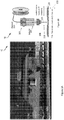
- Figures 1A and 1B illustrate an exemplary additive deposition machine 100 comprising a print head 102, extruder 104, feeder 106, and nozzle 108 for feeding material (e.g., a filament 110) onto a substrate 112 on a build platform or printer bed 114.
- the machine 100 is a desktop Fused Deposition Modeling (FDM) 3D printer.
- Figure 1A further illustrates the anchor points or anchors 116a, 116c deposited on the substrate 112 around, within, or around and within, the region where a two dimensional fibrous architecture is to be deposited..
- FDM Fused Deposition Modeling
- the machine 100 can drag and draw a filament of the material (124) extending from the first anchor 116a at a first position 116b on the substrate 112 to the second anchor 116c at a second position 116d on the substrate 112, by creating a vertical space 118 between the substrate 112 and the print head 102 above the first position 116b of the first anchor 114a, laterally moving (in an x-y plane 120) the print head 102 or the substrate (112), or both the print head (102) and the substrate 112 relative to one another so as to position the print head 102 above the second position 116d and drag and draw the filament between the first position 116b and the second position 116d, and moving the substrate 112 and the print head 102 towards one another in the vertical direction 122 so as to connect the filament to the second anchor 116c.
- Material (124) may be dragged across from one anchor point to another repeatedly to make a pattern of material (124) and the vertical space and lateral translation can be achieved by moving the nozzle (108) and/or the print bed
- the anchor (116a, 116b) is defined as a substrate, foundation, and/or source for the filament (600, 110) providing the material (124) for the filament (600, 110) and/or providing something for the filament (600,110) to stick to once the filament (600) is formed.
- FIG 2A is a flowchart illustrating the process of additively manufacturing a structure on a substrate 112, e.g., using the AM machine illustrated in Figures 1A and 1B .
- Anchor points may be created before or after the connection of the anchor points with filaments (600) .
- Example substrates include, but are not limited to, fibrous substrates comprising fiber tows fabricated from at least one material (124) chosen from fiberglass, kevlar, and carbon.
- the fiber tows are woven, e.g., so as to form a fiber mat.
- the substrate comprises unidirectional tape with regular slits (comprising parallel tows with gaps therebetween), braids (e.g., stitched fabrics), or multi-axial reinforcements.
- Block 200 represents creating (e.g., printing) an anchor (e.g., first anchor (116a) or anchor point) on a surface of a substrate 112.
- the anchor (116a, 116b) is defined as a substrate, foundation, and/or source for the filament (600, 110) providing the material (124) for the filament (600, 110) and/or providing something for the filament (600,110) to stick to once the filament (600) is formed.
- material (124) is deposited from an outlet (e.g., nozzle108)) onto the substrate using the machine illustrated in Figure 1 or Figure 2B(I) .
- the material (124) include at least one material (124) chosen from a polymer (e.g., nylon, polyetherketoneketone (PEKK), polyaryletherketone (PEK), polyimide), carbon, a carbon nanotube, a clay modifier, a thermoplastic (e.g., thermoplastic polymer), a hybrid thermoplastic, and metal.
- a polymer e.g., nylon, polyetherketoneketone (PEKK), polyaryletherketone (PEK), polyimide
- Block 202 represents creating a space between the substrate and the outlet (e.g., nozzle (108)).
- the nozzle translates upwards or the substrate translates downwards.
- the build platform drops away (e.g., vertically) from the nozzle (108) (or the nozzle (108) translates upward or vertically from the substrate) creating a large space between the substrate and the nozzle (108) while extruding/drawing a filament from the nozzle (108), as illustrated in Figure 2B(II) .
- the nozzle (108) pulls on a drop of material while also supplying more of the material (124) to thin the material out into a filament or string.
- Block 204 represents laterally and/or vertically (e.g., horizontally and/or vertically or simultaneously horizontally and vertically) moving the outlet (e.g., nozzle 108) or the substrate (112), or both the outlet and the substrate (112) relative to one another so as to position the outlet above the second position (116d) on the substrate.
- the step includes moving the substrate (112) and/or print head (102) so as to ) translate the print head (102) in mid-air (i.e., with vertical space between the nozzle (108) and the substrate (112)) while drawing/extruding the filament from the outlet.
- a string of thin deposition is created mid air (with vertical space between the nozzle (108) and the substrate (112)) by this movement, e.g., as illustrated in Figure 2B(III) .
- vertical movement during translation creates increased space between the nozzle and the substrate.
- Block 206 represents stopping the outlet and/or the substrate (112) so as to position the outlet at a next location (e.g., second position 116d) above the substrate (112).
- Block 208 represents moving the outlet and/or substrate together again at the next location/position of the next anchor point (e.g., second anchor 116c), e.g., as illustrated in Figure 2B (IV).
- next anchor point e.g., second anchor 116c
- Block 210 represents repeating at least Block 200 to create a second anchor (116c) point on the substrate at the next location, e.g., as illustrated in Figure 2B(V) .
- Steps 200-210 may be repeated in sequence a plurality of times to create a plurality of anchor points and laying material from one anchor to another as the outlet draws or pulls a filament extending from one anchor to the other. In this way, a two dimensional structure or architecture comprising the filaments (600) connecting anchor points is constructed.
- the process may control the form and size of architectures in a single flat/curved plane as opposed to creating a thick "3D" object.
- the architectures or patterns 700c can be deposited on a moving "roller” device, or directly onto a reinforcement.
- FIG. 2C shows formation of the thermoplastic architectures on a flat printer bed in a box (250).
- the DD/E methods described herein may also be implemented out of the printer box", for example, using an extruder head attached to a robot end effector as illustrated in Figure 2D .
- control of the process parameters and inputs enables the simultaneous and/or independent control of diameter of the filaments (600) (can be controlled at a given location by depositing material according to a power law as described below).
- diameter of the filaments is controlled by the nozzle speed relative to the substrate and/or the amount of material/feed rate).
- the action of dragging the material controls the thickness of diameter of the filament (e.g., dragging the material thins the material).
- Thin filaments can be strong but light.
- the material (e.g., thermoplastic) content is minimized by reducing the diameter so as to reduce weight while keeping a threshold strength.
- drawing straight sections of (e.g., thermoplastic) filaments (600) between two “anchor points” at high speed reduces the filament diameter, uses less material, provides extended control over the thermoplastic material properties on a localized basis, and increases manufacturing speed.
- Examples of print conditions during creation of the anchors and/or drawing of the filaments include, but are not limited to, the following.
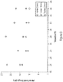
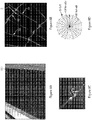
- Figures 3 , 4 , and 5 illustrate how additive manufacturing deposition conditions (nozzle temperature) changes and/or controls the material properties of the filaments.
- the variations in the tensile strength and engineering strain have been included as examples, however other material properties can also be controlled through the additive manufacturing process by controlling influential printer inputs, such as feed rate, thermoplastic flow rate, and nozzle temperature.
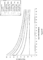
- Figure 6A plots fiber diameter as a function of print speed and nozzle temperature.
- the diameter D of the filament (600) was found to be a function of flow rate (F rate ) of material (124) into and out of the nozzle (108)), seep or flow rate (m seep ) of material flowing under gravity from extruder (104) into nozzle, and time (t delay ) taken moving the nozzle from one point (e.g., first position 116b) to another point (e.g., second position 116d) above the substrate).
- F rate flow rate
- m seep seep
- the power law equation was generated using empirical data and physics based relationships and relates how to control the filament diameter as a function of extrusion temperature, head translation speed (mm/sec), and thermoplastic flow rate (g/min).
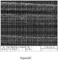
- Figures 6B-6D are results confirming how thinner filament lines can be fabricated by having the printer head farther away and/or by varying the printer head speed.
- the printer head speed is the same as the speed of the nozzle (108) connected to the printer head.
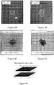
- Figure 6E illustrates how the DD/E method controls direction of the filaments, spacing of the filaments, and filament diameter, and aerial weight as a function of position in the x-y plane (in region A, the filament diameter is 0.04mm, in region B the filament diameter is 0.03 mm).
- FIG 7A illustrates a structure (700) fabricated using the method illustrated in Figure 2 .
- the structure (700) comprises a plurality of anchors (116a, 116c) on a substrate (112); and a two dimensional network (702) of interconnected filaments (600) comprising a thermoplastic drawn between the anchors (116a, 116b).
- Example dimensions for the anchors include a minimum diameter D2 in a range of 0.25-mm to 2.0-mm.
- Example dimensions for the filaments 600 include a diameter D in the range of 30-400 micrometers.
- Example lengths L of the filaments include a length in a range of 5 cm to 10 meters (e.g., so that the two dimensional network has a diameter, width W, or length L in a range of 5 cm to 10 meters).
- the structure 700 illustrated in Figures 7A-7C is a veil 700b interlaminar architecture for implementation in a laminated composite material system (veil toughened composite).
- the a toughened composite includes a plurality of alternating layers alternating between the carbon fiber mat and the two dimensional structure.
- embodiments of the DD/E method provide much greater flexibility in design of architectures for interlayer toughening technologies, including, but not limited to, control over direction of the filaments, diameter of filaments, and location of the filament.
- Figures 8A, 8B, 8C, and 8D illustrate an example where the structure 700 comprises a web 800 including filaments 600 disposed in nested rings 802 as well as radially so as to connect the rings 802.
- the location of the radially disposed filaments 804, the mesh width 806 (see Figure 8D ), the filament diameter D (e.g., in a range of 7-150 microns), the web radius 808, the areal weight (e.g., in a range of 1.5- 2.5 gsm), surface morphology of the filaments, may all be varied locally in the two dimensional plane, as desired.
- the web is designed to mimic the performance of a spider's web.
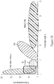
- Figures 9A-9D illustrate the performance of a toughened composite wherein the veil layer comprises a web architecture as illustrated herein.
- the data shows >30% reduction in length and area of the impact damage area 900, spherical crack containment, dent depth under a 270-in.lb impact in a range of 0.014 to 0.016-inches, and compression after impact CAI under a 270-in.lb impact of 30 ksi (vs 25 ksi as compared to a control device where the veil layer comprises randomly disposed fibers as illustrated in Figure 9E ).
- Figure 10 shows that the spider based web structure described herein performs at least as well as nanofibrous interleaves.
- the two dimensional fibrous architectures are not limited to veils or a toughening architectures.
- the two dimensional structure is used as an adhesive or mechanical interlocking device.
- the adhesive comprises one surface including the two dimensional network of filaments and another surface including hooks, wherein the surfaces are adhered when the hooks hook onto the filaments.
- FIG. 11 illustrates an exemplary system 1100 used to implement processing elements needed to control the AM machine described herein.
- the computer 1102 comprises a processor 1104 (general purpose processor 1104A and special purpose processor 1104B) and a memory, such as random access memory (RAM) 1106.
- the computer 1102 operates under control of an operating system 1108 stored in the memory 1106, and interfaces with the user/other computers to accept inputs and commands (e.g., analog or digital signals) and to present results through an input/output (I/O) module 1110.
- the computer program application 1112 accesses and manipulates data stored in the memory 1106 of the computer 1102.
- the operating system 1108 and the computer program 1112 are comprised of instructions which, when read and executed by the computer 1102, cause the computer 1102 to perform the operations herein described.
- instructions implementing the operating system 1108 and the computer program 1112 are tangibly embodied in the memory 1106, thereby making one or more computer program products or articles of manufacture capable of controlling AM process parameters including, but not limited to, filament feed rate and nozzle temperature, speed, and position, in accordance with the design of the structures being fabricated.
- the terms "article of manufacture,” “program storage device” and “computer program product” as used herein are intended to encompass a computer program accessible from any computer readable device or media.
- the computer program is implemented in a numerical control programming language.
Landscapes
- Engineering & Computer Science (AREA)
- Chemical & Material Sciences (AREA)
- Materials Engineering (AREA)
- Manufacturing & Machinery (AREA)
- Physics & Mathematics (AREA)
- Mechanical Engineering (AREA)
- Optics & Photonics (AREA)
- Life Sciences & Earth Sciences (AREA)
- Wood Science & Technology (AREA)
- Nonwoven Fabrics (AREA)
Applications Claiming Priority (1)
| Application Number | Priority Date | Filing Date | Title |
|---|---|---|---|
| US15/957,050 US10583605B2 (en) | 2018-04-19 | 2018-04-19 | Drop draw/extrude (DD/E) printing method |
Publications (2)
| Publication Number | Publication Date |
|---|---|
| EP3564012A1 true EP3564012A1 (de) | 2019-11-06 |
| EP3564012B1 EP3564012B1 (de) | 2021-12-22 |
Family
ID=66102890
Family Applications (1)
| Application Number | Title | Priority Date | Filing Date |
|---|---|---|---|
| EP19167994.3A Active EP3564012B1 (de) | 2018-04-19 | 2019-04-08 | Auftragen-ziehen-extrudieren druckverfahren |
Country Status (8)
| Country | Link |
|---|---|
| US (2) | US10583605B2 (de) |
| EP (1) | EP3564012B1 (de) |
| JP (1) | JP2019195996A (de) |
| KR (1) | KR20190130470A (de) |
| CN (1) | CN110385851B (de) |
| AU (1) | AU2019202653B2 (de) |
| CA (1) | CA3040178C (de) |
| RU (1) | RU2019108321A (de) |
Cited By (2)
| Publication number | Priority date | Publication date | Assignee | Title |
|---|---|---|---|---|
| EP3908449B1 (de) * | 2019-01-08 | 2024-04-10 | Signify Holding B.V. | Tropfdrucken |
| EP4489959A4 (de) * | 2022-03-09 | 2026-04-08 | Loophole Ltd | Verfahren und system zur herstellung von kleidungsstücken und geweben |
Families Citing this family (10)
| Publication number | Priority date | Publication date | Assignee | Title |
|---|---|---|---|---|
| US10583605B2 (en) * | 2018-04-19 | 2020-03-10 | The Boeing Company | Drop draw/extrude (DD/E) printing method |
| US10940648B2 (en) | 2018-04-19 | 2021-03-09 | The Boeing Company | Three dimensional printed fibrous interlocking interlayers |
| GB2584701B (en) * | 2019-06-12 | 2022-01-05 | Ai Build Ltd | Collision avoidance in three-dimensional printing |
| US11945154B2 (en) * | 2019-11-18 | 2024-04-02 | Pablo Gabriel de León | Printer and printing method for space and pressure suits using additive manufacturing |
| CN112373012B (zh) * | 2020-10-23 | 2022-08-26 | 湖北屹安医疗器械有限公司 | 多喷头3d打印控制系统及方法 |
| CN112157907B (zh) * | 2020-10-23 | 2022-08-26 | 湖北屹安医疗器械有限公司 | 多喷头高速3d打印系统 |
| US11964441B2 (en) | 2021-02-01 | 2024-04-23 | The Boeing Company | Composite part with additively manufactured sub-structure |
| CN115091751B (zh) * | 2022-07-15 | 2025-07-11 | 上海轮廓科技有限公司 | 3d打印机及用于其的方法和装置、3d打印系统和存储介质 |
| CN115519788B (zh) * | 2022-09-06 | 2024-03-15 | 深圳先进技术研究院 | 组织工程支架的打印方法、打印系统、终端及存储介质 |
| CN115476508A (zh) * | 2022-09-06 | 2022-12-16 | 深圳先进技术研究院 | 连续变纤维直径的挤出式3d打印方法、打印系统和应用 |
Citations (1)
| Publication number | Priority date | Publication date | Assignee | Title |
|---|---|---|---|---|
| WO2017100783A1 (en) * | 2015-12-11 | 2017-06-15 | Massachusetts Institute Of Technology | Systems, devices, and methods for deposition-based three-dimensional printing |
Family Cites Families (16)
| Publication number | Priority date | Publication date | Assignee | Title |
|---|---|---|---|---|
| US4001366A (en) | 1972-01-03 | 1977-01-04 | Ingrip Fasteners Inc. | Method for making self-gripping devices having integral trains of gripping elements |
| US6422848B1 (en) * | 1997-03-19 | 2002-07-23 | Nordson Corporation | Modular meltblowing die |
| US20020112325A1 (en) | 2000-12-18 | 2002-08-22 | Cape Cod Research, Inc. | Drapable surface fastener and method of using same |
| WO2008054759A2 (en) | 2006-10-31 | 2008-05-08 | U Mass Dartmouth - Central | Fabric based laminar composite and method for manufacture thereof |
| US8123886B2 (en) | 2008-09-17 | 2012-02-28 | General Electric Company | Method of manufacture of composite laminates, an assembly therefor, and related articles |
| US8609219B2 (en) | 2010-12-15 | 2013-12-17 | The Boeing Company | Selectively coupled fibers in composites |
| CA3121870A1 (en) * | 2013-03-22 | 2014-09-25 | Markforged, Inc. | Three dimensional printing |
| EP3003694B1 (de) | 2013-05-31 | 2018-10-10 | United Technologies Corporation | Herstellung einer endlosfaserverstärkten komponente |
| KR101415646B1 (ko) | 2013-07-17 | 2014-07-04 | 한국항공우주연구원 | 요철 형상을 갖는 z-핀 제조 방법 및 상기 방법으로 제조된 z-핀 |
| WO2015047480A2 (en) | 2013-08-20 | 2015-04-02 | United Technologies Corporation | Composite flange with three-dimensional weave architecture |
| US10081722B2 (en) | 2014-03-25 | 2018-09-25 | The Boeing Company | Three-dimensional filament network for a composite laminate |
| US9845556B2 (en) | 2014-09-23 | 2017-12-19 | The Boeing Company | Printing patterns onto composite laminates |
| DE112014007131T5 (de) * | 2014-11-04 | 2017-07-20 | Nv Bekaert Sa | Verstärkungsgewebe zum Verstärken eines schlagfesten oder strukturellen Verbundteils |
| US9474331B2 (en) * | 2015-02-03 | 2016-10-25 | Nike, Inc. | Method of making an article of footwear having printed structures |
| CN112385933B (zh) * | 2015-12-07 | 2022-03-29 | 耐克创新有限合伙公司 | 具有带突片部分的管状结构的鞋类物品 |
| US10583605B2 (en) * | 2018-04-19 | 2020-03-10 | The Boeing Company | Drop draw/extrude (DD/E) printing method |
-
2018
- 2018-04-19 US US15/957,050 patent/US10583605B2/en active Active
-
2019
- 2019-03-21 KR KR1020190032211A patent/KR20190130470A/ko not_active Ceased
- 2019-03-22 RU RU2019108321A patent/RU2019108321A/ru unknown
- 2019-04-04 JP JP2019072128A patent/JP2019195996A/ja active Pending
- 2019-04-08 EP EP19167994.3A patent/EP3564012B1/de active Active
- 2019-04-11 CA CA3040178A patent/CA3040178C/en active Active
- 2019-04-11 CN CN201910306181.3A patent/CN110385851B/zh active Active
- 2019-04-16 AU AU2019202653A patent/AU2019202653B2/en active Active
-
2020
- 2020-01-31 US US16/779,287 patent/US11130279B2/en active Active
Patent Citations (1)
| Publication number | Priority date | Publication date | Assignee | Title |
|---|---|---|---|---|
| WO2017100783A1 (en) * | 2015-12-11 | 2017-06-15 | Massachusetts Institute Of Technology | Systems, devices, and methods for deposition-based three-dimensional printing |
Non-Patent Citations (1)
| Title |
|---|
| ZHAO QIN ET AL: "Structural optimization of 3D-printed synthetic spider webs for high strength", NATURE COMMUNICATIONS, vol. 6, no. 1, 15 May 2015 (2015-05-15), XP055625378, DOI: 10.1038/ncomms8038 * |
Cited By (2)
| Publication number | Priority date | Publication date | Assignee | Title |
|---|---|---|---|---|
| EP3908449B1 (de) * | 2019-01-08 | 2024-04-10 | Signify Holding B.V. | Tropfdrucken |
| EP4489959A4 (de) * | 2022-03-09 | 2026-04-08 | Loophole Ltd | Verfahren und system zur herstellung von kleidungsstücken und geweben |
Also Published As
| Publication number | Publication date |
|---|---|
| CN110385851B (zh) | 2023-06-23 |
| EP3564012B1 (de) | 2021-12-22 |
| AU2019202653B2 (en) | 2023-12-14 |
| US20190322037A1 (en) | 2019-10-24 |
| US10583605B2 (en) | 2020-03-10 |
| JP2019195996A (ja) | 2019-11-14 |
| US11130279B2 (en) | 2021-09-28 |
| CN110385851A (zh) | 2019-10-29 |
| CA3040178C (en) | 2023-06-27 |
| US20200164570A1 (en) | 2020-05-28 |
| AU2019202653A1 (en) | 2019-11-07 |
| RU2019108321A (ru) | 2020-09-22 |
| KR20190130470A (ko) | 2019-11-22 |
| CA3040178A1 (en) | 2019-10-19 |
Similar Documents
| Publication | Publication Date | Title |
|---|---|---|
| US11130279B2 (en) | Drop draw/extrude (DD/E) printing method | |
| AU2019202652B2 (en) | Thermoplastic cellular network toughened composites | |
| JP5703785B2 (ja) | 複合口金 | |
| EP3556557B1 (de) | Faserverbundverstärkung unter verwendung dreidimensionaler gedruckter thermoplastischer stifte | |
| EP3781393B1 (de) | Faserige ineinandergreifende zwischenschichten | |
| WO2015028809A1 (en) | Improvements relating to fused deposition modelling | |
| WO2021127329A1 (en) | Multifilament feedstocks for fused deposition modeling | |
| EP4094924A1 (de) | 3d-druckwulstkonfiguration |
Legal Events
| Date | Code | Title | Description |
|---|---|---|---|
| PUAI | Public reference made under article 153(3) epc to a published international application that has entered the european phase |
Free format text: ORIGINAL CODE: 0009012 |
|
| STAA | Information on the status of an ep patent application or granted ep patent |
Free format text: STATUS: REQUEST FOR EXAMINATION WAS MADE |
|
| 17P | Request for examination filed |
Effective date: 20190408 |
|
| AK | Designated contracting states |
Kind code of ref document: A1 Designated state(s): AL AT BE BG CH CY CZ DE DK EE ES FI FR GB GR HR HU IE IS IT LI LT LU LV MC MK MT NL NO PL PT RO RS SE SI SK SM TR |
|
| AX | Request for extension of the european patent |
Extension state: BA ME |
|
| GRAP | Despatch of communication of intention to grant a patent |
Free format text: ORIGINAL CODE: EPIDOSNIGR1 |
|
| STAA | Information on the status of an ep patent application or granted ep patent |
Free format text: STATUS: GRANT OF PATENT IS INTENDED |
|
| INTG | Intention to grant announced |
Effective date: 20210331 |
|
| GRAJ | Information related to disapproval of communication of intention to grant by the applicant or resumption of examination proceedings by the epo deleted |
Free format text: ORIGINAL CODE: EPIDOSDIGR1 |
|
| STAA | Information on the status of an ep patent application or granted ep patent |
Free format text: STATUS: REQUEST FOR EXAMINATION WAS MADE |
|
| GRAP | Despatch of communication of intention to grant a patent |
Free format text: ORIGINAL CODE: EPIDOSNIGR1 |
|
| INTC | Intention to grant announced (deleted) | ||
| STAA | Information on the status of an ep patent application or granted ep patent |
Free format text: STATUS: GRANT OF PATENT IS INTENDED |
|
| INTG | Intention to grant announced |
Effective date: 20210715 |
|
| GRAS | Grant fee paid |
Free format text: ORIGINAL CODE: EPIDOSNIGR3 |
|
| GRAA | (expected) grant |
Free format text: ORIGINAL CODE: 0009210 |
|
| STAA | Information on the status of an ep patent application or granted ep patent |
Free format text: STATUS: THE PATENT HAS BEEN GRANTED |
|
| AK | Designated contracting states |
Kind code of ref document: B1 Designated state(s): AL AT BE BG CH CY CZ DE DK EE ES FI FR GB GR HR HU IE IS IT LI LT LU LV MC MK MT NL NO PL PT RO RS SE SI SK SM TR |
|
| REG | Reference to a national code |
Ref country code: GB Ref legal event code: FG4D |
|
| REG | Reference to a national code |
Ref country code: CH Ref legal event code: EP |
|
| REG | Reference to a national code |
Ref country code: DE Ref legal event code: R096 Ref document number: 602019010186 Country of ref document: DE |
|
| REG | Reference to a national code |
Ref country code: AT Ref legal event code: REF Ref document number: 1456817 Country of ref document: AT Kind code of ref document: T Effective date: 20220115 |
|
| REG | Reference to a national code |
Ref country code: IE Ref legal event code: FG4D |
|
| REG | Reference to a national code |
Ref country code: LT Ref legal event code: MG9D |
|
| PG25 | Lapsed in a contracting state [announced via postgrant information from national office to epo] |
Ref country code: RS Free format text: LAPSE BECAUSE OF FAILURE TO SUBMIT A TRANSLATION OF THE DESCRIPTION OR TO PAY THE FEE WITHIN THE PRESCRIBED TIME-LIMIT Effective date: 20211222 Ref country code: LT Free format text: LAPSE BECAUSE OF FAILURE TO SUBMIT A TRANSLATION OF THE DESCRIPTION OR TO PAY THE FEE WITHIN THE PRESCRIBED TIME-LIMIT Effective date: 20211222 Ref country code: FI Free format text: LAPSE BECAUSE OF FAILURE TO SUBMIT A TRANSLATION OF THE DESCRIPTION OR TO PAY THE FEE WITHIN THE PRESCRIBED TIME-LIMIT Effective date: 20211222 Ref country code: BG Free format text: LAPSE BECAUSE OF FAILURE TO SUBMIT A TRANSLATION OF THE DESCRIPTION OR TO PAY THE FEE WITHIN THE PRESCRIBED TIME-LIMIT Effective date: 20220322 |
|
| REG | Reference to a national code |
Ref country code: NL Ref legal event code: MP Effective date: 20211222 |
|
| REG | Reference to a national code |
Ref country code: AT Ref legal event code: MK05 Ref document number: 1456817 Country of ref document: AT Kind code of ref document: T Effective date: 20211222 |
|
| PG25 | Lapsed in a contracting state [announced via postgrant information from national office to epo] |
Ref country code: SE Free format text: LAPSE BECAUSE OF FAILURE TO SUBMIT A TRANSLATION OF THE DESCRIPTION OR TO PAY THE FEE WITHIN THE PRESCRIBED TIME-LIMIT Effective date: 20211222 Ref country code: NO Free format text: LAPSE BECAUSE OF FAILURE TO SUBMIT A TRANSLATION OF THE DESCRIPTION OR TO PAY THE FEE WITHIN THE PRESCRIBED TIME-LIMIT Effective date: 20220322 Ref country code: LV Free format text: LAPSE BECAUSE OF FAILURE TO SUBMIT A TRANSLATION OF THE DESCRIPTION OR TO PAY THE FEE WITHIN THE PRESCRIBED TIME-LIMIT Effective date: 20211222 Ref country code: HR Free format text: LAPSE BECAUSE OF FAILURE TO SUBMIT A TRANSLATION OF THE DESCRIPTION OR TO PAY THE FEE WITHIN THE PRESCRIBED TIME-LIMIT Effective date: 20211222 Ref country code: GR Free format text: LAPSE BECAUSE OF FAILURE TO SUBMIT A TRANSLATION OF THE DESCRIPTION OR TO PAY THE FEE WITHIN THE PRESCRIBED TIME-LIMIT Effective date: 20220323 |
|
| PG25 | Lapsed in a contracting state [announced via postgrant information from national office to epo] |
Ref country code: NL Free format text: LAPSE BECAUSE OF FAILURE TO SUBMIT A TRANSLATION OF THE DESCRIPTION OR TO PAY THE FEE WITHIN THE PRESCRIBED TIME-LIMIT Effective date: 20211222 |
|
| PG25 | Lapsed in a contracting state [announced via postgrant information from national office to epo] |
Ref country code: SM Free format text: LAPSE BECAUSE OF FAILURE TO SUBMIT A TRANSLATION OF THE DESCRIPTION OR TO PAY THE FEE WITHIN THE PRESCRIBED TIME-LIMIT Effective date: 20211222 Ref country code: SK Free format text: LAPSE BECAUSE OF FAILURE TO SUBMIT A TRANSLATION OF THE DESCRIPTION OR TO PAY THE FEE WITHIN THE PRESCRIBED TIME-LIMIT Effective date: 20211222 Ref country code: RO Free format text: LAPSE BECAUSE OF FAILURE TO SUBMIT A TRANSLATION OF THE DESCRIPTION OR TO PAY THE FEE WITHIN THE PRESCRIBED TIME-LIMIT Effective date: 20211222 Ref country code: PT Free format text: LAPSE BECAUSE OF FAILURE TO SUBMIT A TRANSLATION OF THE DESCRIPTION OR TO PAY THE FEE WITHIN THE PRESCRIBED TIME-LIMIT Effective date: 20220422 Ref country code: ES Free format text: LAPSE BECAUSE OF FAILURE TO SUBMIT A TRANSLATION OF THE DESCRIPTION OR TO PAY THE FEE WITHIN THE PRESCRIBED TIME-LIMIT Effective date: 20211222 Ref country code: EE Free format text: LAPSE BECAUSE OF FAILURE TO SUBMIT A TRANSLATION OF THE DESCRIPTION OR TO PAY THE FEE WITHIN THE PRESCRIBED TIME-LIMIT Effective date: 20211222 Ref country code: CZ Free format text: LAPSE BECAUSE OF FAILURE TO SUBMIT A TRANSLATION OF THE DESCRIPTION OR TO PAY THE FEE WITHIN THE PRESCRIBED TIME-LIMIT Effective date: 20211222 |
|
| PG25 | Lapsed in a contracting state [announced via postgrant information from national office to epo] |
Ref country code: PL Free format text: LAPSE BECAUSE OF FAILURE TO SUBMIT A TRANSLATION OF THE DESCRIPTION OR TO PAY THE FEE WITHIN THE PRESCRIBED TIME-LIMIT Effective date: 20211222 Ref country code: AT Free format text: LAPSE BECAUSE OF FAILURE TO SUBMIT A TRANSLATION OF THE DESCRIPTION OR TO PAY THE FEE WITHIN THE PRESCRIBED TIME-LIMIT Effective date: 20211222 |
|
| REG | Reference to a national code |
Ref country code: DE Ref legal event code: R097 Ref document number: 602019010186 Country of ref document: DE |
|
| PG25 | Lapsed in a contracting state [announced via postgrant information from national office to epo] |
Ref country code: IS Free format text: LAPSE BECAUSE OF FAILURE TO SUBMIT A TRANSLATION OF THE DESCRIPTION OR TO PAY THE FEE WITHIN THE PRESCRIBED TIME-LIMIT Effective date: 20220422 |
|
| PLBE | No opposition filed within time limit |
Free format text: ORIGINAL CODE: 0009261 |
|
| STAA | Information on the status of an ep patent application or granted ep patent |
Free format text: STATUS: NO OPPOSITION FILED WITHIN TIME LIMIT |
|
| PG25 | Lapsed in a contracting state [announced via postgrant information from national office to epo] |
Ref country code: DK Free format text: LAPSE BECAUSE OF FAILURE TO SUBMIT A TRANSLATION OF THE DESCRIPTION OR TO PAY THE FEE WITHIN THE PRESCRIBED TIME-LIMIT Effective date: 20211222 Ref country code: AL Free format text: LAPSE BECAUSE OF FAILURE TO SUBMIT A TRANSLATION OF THE DESCRIPTION OR TO PAY THE FEE WITHIN THE PRESCRIBED TIME-LIMIT Effective date: 20211222 |
|
| 26N | No opposition filed |
Effective date: 20220923 |
|
| REG | Reference to a national code |
Ref country code: CH Ref legal event code: PL |
|
| REG | Reference to a national code |
Ref country code: BE Ref legal event code: MM Effective date: 20220430 |
|
| PG25 | Lapsed in a contracting state [announced via postgrant information from national office to epo] |
Ref country code: MC Free format text: LAPSE BECAUSE OF FAILURE TO SUBMIT A TRANSLATION OF THE DESCRIPTION OR TO PAY THE FEE WITHIN THE PRESCRIBED TIME-LIMIT Effective date: 20211222 Ref country code: LU Free format text: LAPSE BECAUSE OF NON-PAYMENT OF DUE FEES Effective date: 20220408 Ref country code: LI Free format text: LAPSE BECAUSE OF NON-PAYMENT OF DUE FEES Effective date: 20220430 Ref country code: CH Free format text: LAPSE BECAUSE OF NON-PAYMENT OF DUE FEES Effective date: 20220430 |
|
| PG25 | Lapsed in a contracting state [announced via postgrant information from national office to epo] |
Ref country code: SI Free format text: LAPSE BECAUSE OF FAILURE TO SUBMIT A TRANSLATION OF THE DESCRIPTION OR TO PAY THE FEE WITHIN THE PRESCRIBED TIME-LIMIT Effective date: 20211222 Ref country code: BE Free format text: LAPSE BECAUSE OF NON-PAYMENT OF DUE FEES Effective date: 20220430 |
|
| PG25 | Lapsed in a contracting state [announced via postgrant information from national office to epo] |
Ref country code: IE Free format text: LAPSE BECAUSE OF NON-PAYMENT OF DUE FEES Effective date: 20220408 |
|
| PG25 | Lapsed in a contracting state [announced via postgrant information from national office to epo] |
Ref country code: IT Free format text: LAPSE BECAUSE OF FAILURE TO SUBMIT A TRANSLATION OF THE DESCRIPTION OR TO PAY THE FEE WITHIN THE PRESCRIBED TIME-LIMIT Effective date: 20211222 |
|
| P01 | Opt-out of the competence of the unified patent court (upc) registered |
Effective date: 20230516 |
|
| PG25 | Lapsed in a contracting state [announced via postgrant information from national office to epo] |
Ref country code: HU Free format text: LAPSE BECAUSE OF FAILURE TO SUBMIT A TRANSLATION OF THE DESCRIPTION OR TO PAY THE FEE WITHIN THE PRESCRIBED TIME-LIMIT; INVALID AB INITIO Effective date: 20190408 |
|
| PG25 | Lapsed in a contracting state [announced via postgrant information from national office to epo] |
Ref country code: MK Free format text: LAPSE BECAUSE OF FAILURE TO SUBMIT A TRANSLATION OF THE DESCRIPTION OR TO PAY THE FEE WITHIN THE PRESCRIBED TIME-LIMIT Effective date: 20211222 Ref country code: CY Free format text: LAPSE BECAUSE OF FAILURE TO SUBMIT A TRANSLATION OF THE DESCRIPTION OR TO PAY THE FEE WITHIN THE PRESCRIBED TIME-LIMIT Effective date: 20211222 |
|
| PG25 | Lapsed in a contracting state [announced via postgrant information from national office to epo] |
Ref country code: TR Free format text: LAPSE BECAUSE OF FAILURE TO SUBMIT A TRANSLATION OF THE DESCRIPTION OR TO PAY THE FEE WITHIN THE PRESCRIBED TIME-LIMIT Effective date: 20211222 |
|
| PG25 | Lapsed in a contracting state [announced via postgrant information from national office to epo] |
Ref country code: MT Free format text: LAPSE BECAUSE OF FAILURE TO SUBMIT A TRANSLATION OF THE DESCRIPTION OR TO PAY THE FEE WITHIN THE PRESCRIBED TIME-LIMIT Effective date: 20211222 |
|
| PGFP | Annual fee paid to national office [announced via postgrant information from national office to epo] |
Ref country code: DE Payment date: 20250429 Year of fee payment: 7 |
|
| PGFP | Annual fee paid to national office [announced via postgrant information from national office to epo] |
Ref country code: GB Payment date: 20250428 Year of fee payment: 7 |
|
| PGFP | Annual fee paid to national office [announced via postgrant information from national office to epo] |
Ref country code: FR Payment date: 20250425 Year of fee payment: 7 |