EP3564111B1 - Système d'assistance électrique et véhicule à assistance électrique - Google Patents
Système d'assistance électrique et véhicule à assistance électrique Download PDFInfo
- Publication number
- EP3564111B1 EP3564111B1 EP17888447.4A EP17888447A EP3564111B1 EP 3564111 B1 EP3564111 B1 EP 3564111B1 EP 17888447 A EP17888447 A EP 17888447A EP 3564111 B1 EP3564111 B1 EP 3564111B1
- Authority
- EP
- European Patent Office
- Prior art keywords
- electric
- acceleration
- motor
- assist
- torque
- Prior art date
- Legal status (The legal status is an assumption and is not a legal conclusion. Google has not performed a legal analysis and makes no representation as to the accuracy of the status listed.)
- Active
Links
Images





Classifications
-
- B—PERFORMING OPERATIONS; TRANSPORTING
- B60—VEHICLES IN GENERAL
- B60L—PROPULSION OF ELECTRICALLY-PROPELLED VEHICLES; SUPPLYING ELECTRIC POWER FOR AUXILIARY EQUIPMENT OF ELECTRICALLY-PROPELLED VEHICLES; ELECTRODYNAMIC BRAKE SYSTEMS FOR VEHICLES IN GENERAL; MAGNETIC SUSPENSION OR LEVITATION FOR VEHICLES; MONITORING OPERATING VARIABLES OF ELECTRICALLY-PROPELLED VEHICLES; ELECTRIC SAFETY DEVICES FOR ELECTRICALLY-PROPELLED VEHICLES
- B60L15/00—Methods, circuits, or devices for controlling the traction-motor speed of electrically-propelled vehicles
- B60L15/20—Methods, circuits, or devices for controlling the traction-motor speed of electrically-propelled vehicles for control of the vehicle or its driving motor to achieve a desired performance, e.g. speed, torque, programmed variation of speed
- B60L15/2045—Methods, circuits, or devices for controlling the traction-motor speed of electrically-propelled vehicles for control of the vehicle or its driving motor to achieve a desired performance, e.g. speed, torque, programmed variation of speed for optimising the use of energy
-
- B—PERFORMING OPERATIONS; TRANSPORTING
- B60—VEHICLES IN GENERAL
- B60L—PROPULSION OF ELECTRICALLY-PROPELLED VEHICLES; SUPPLYING ELECTRIC POWER FOR AUXILIARY EQUIPMENT OF ELECTRICALLY-PROPELLED VEHICLES; ELECTRODYNAMIC BRAKE SYSTEMS FOR VEHICLES IN GENERAL; MAGNETIC SUSPENSION OR LEVITATION FOR VEHICLES; MONITORING OPERATING VARIABLES OF ELECTRICALLY-PROPELLED VEHICLES; ELECTRIC SAFETY DEVICES FOR ELECTRICALLY-PROPELLED VEHICLES
- B60L15/00—Methods, circuits, or devices for controlling the traction-motor speed of electrically-propelled vehicles
- B60L15/20—Methods, circuits, or devices for controlling the traction-motor speed of electrically-propelled vehicles for control of the vehicle or its driving motor to achieve a desired performance, e.g. speed, torque, programmed variation of speed
- B60L15/2054—Methods, circuits, or devices for controlling the traction-motor speed of electrically-propelled vehicles for control of the vehicle or its driving motor to achieve a desired performance, e.g. speed, torque, programmed variation of speed by controlling transmissions or clutches
-
- B—PERFORMING OPERATIONS; TRANSPORTING
- B60—VEHICLES IN GENERAL
- B60L—PROPULSION OF ELECTRICALLY-PROPELLED VEHICLES; SUPPLYING ELECTRIC POWER FOR AUXILIARY EQUIPMENT OF ELECTRICALLY-PROPELLED VEHICLES; ELECTRODYNAMIC BRAKE SYSTEMS FOR VEHICLES IN GENERAL; MAGNETIC SUSPENSION OR LEVITATION FOR VEHICLES; MONITORING OPERATING VARIABLES OF ELECTRICALLY-PROPELLED VEHICLES; ELECTRIC SAFETY DEVICES FOR ELECTRICALLY-PROPELLED VEHICLES
- B60L15/00—Methods, circuits, or devices for controlling the traction-motor speed of electrically-propelled vehicles
- B60L15/20—Methods, circuits, or devices for controlling the traction-motor speed of electrically-propelled vehicles for control of the vehicle or its driving motor to achieve a desired performance, e.g. speed, torque, programmed variation of speed
- B60L15/2036—Electric differentials, e.g. for supporting steering vehicles
-
- B—PERFORMING OPERATIONS; TRANSPORTING
- B60—VEHICLES IN GENERAL
- B60L—PROPULSION OF ELECTRICALLY-PROPELLED VEHICLES; SUPPLYING ELECTRIC POWER FOR AUXILIARY EQUIPMENT OF ELECTRICALLY-PROPELLED VEHICLES; ELECTRODYNAMIC BRAKE SYSTEMS FOR VEHICLES IN GENERAL; MAGNETIC SUSPENSION OR LEVITATION FOR VEHICLES; MONITORING OPERATING VARIABLES OF ELECTRICALLY-PROPELLED VEHICLES; ELECTRIC SAFETY DEVICES FOR ELECTRICALLY-PROPELLED VEHICLES
- B60L50/00—Electric propulsion with power supplied within the vehicle
- B60L50/20—Electric propulsion with power supplied within the vehicle using propulsion power generated by humans or animals
-
- B—PERFORMING OPERATIONS; TRANSPORTING
- B62—LAND VEHICLES FOR TRAVELLING OTHERWISE THAN ON RAILS
- B62M—RIDER PROPULSION OF WHEELED VEHICLES OR SLEDGES; POWERED PROPULSION OF SLEDGES OR SINGLE-TRACK CYCLES; TRANSMISSIONS SPECIALLY ADAPTED FOR SUCH VEHICLES
- B62M6/00—Rider propulsion of wheeled vehicles with additional source of power, e.g. combustion engine or electric motor
- B62M6/40—Rider propelled cycles with auxiliary electric motor
- B62M6/45—Control or actuating devices therefor
-
- B—PERFORMING OPERATIONS; TRANSPORTING
- B60—VEHICLES IN GENERAL
- B60L—PROPULSION OF ELECTRICALLY-PROPELLED VEHICLES; SUPPLYING ELECTRIC POWER FOR AUXILIARY EQUIPMENT OF ELECTRICALLY-PROPELLED VEHICLES; ELECTRODYNAMIC BRAKE SYSTEMS FOR VEHICLES IN GENERAL; MAGNETIC SUSPENSION OR LEVITATION FOR VEHICLES; MONITORING OPERATING VARIABLES OF ELECTRICALLY-PROPELLED VEHICLES; ELECTRIC SAFETY DEVICES FOR ELECTRICALLY-PROPELLED VEHICLES
- B60L2200/00—Type of vehicles
- B60L2200/12—Bikes
-
- B—PERFORMING OPERATIONS; TRANSPORTING
- B60—VEHICLES IN GENERAL
- B60L—PROPULSION OF ELECTRICALLY-PROPELLED VEHICLES; SUPPLYING ELECTRIC POWER FOR AUXILIARY EQUIPMENT OF ELECTRICALLY-PROPELLED VEHICLES; ELECTRODYNAMIC BRAKE SYSTEMS FOR VEHICLES IN GENERAL; MAGNETIC SUSPENSION OR LEVITATION FOR VEHICLES; MONITORING OPERATING VARIABLES OF ELECTRICALLY-PROPELLED VEHICLES; ELECTRIC SAFETY DEVICES FOR ELECTRICALLY-PROPELLED VEHICLES
- B60L2240/00—Control parameters of input or output; Target parameters
- B60L2240/10—Vehicle control parameters
- B60L2240/14—Acceleration
- B60L2240/16—Acceleration longitudinal
-
- B—PERFORMING OPERATIONS; TRANSPORTING
- B60—VEHICLES IN GENERAL
- B60L—PROPULSION OF ELECTRICALLY-PROPELLED VEHICLES; SUPPLYING ELECTRIC POWER FOR AUXILIARY EQUIPMENT OF ELECTRICALLY-PROPELLED VEHICLES; ELECTRODYNAMIC BRAKE SYSTEMS FOR VEHICLES IN GENERAL; MAGNETIC SUSPENSION OR LEVITATION FOR VEHICLES; MONITORING OPERATING VARIABLES OF ELECTRICALLY-PROPELLED VEHICLES; ELECTRIC SAFETY DEVICES FOR ELECTRICALLY-PROPELLED VEHICLES
- B60L2240/00—Control parameters of input or output; Target parameters
- B60L2240/40—Drive Train control parameters
- B60L2240/42—Drive Train control parameters related to electric machines
- B60L2240/421—Speed
-
- B—PERFORMING OPERATIONS; TRANSPORTING
- B60—VEHICLES IN GENERAL
- B60L—PROPULSION OF ELECTRICALLY-PROPELLED VEHICLES; SUPPLYING ELECTRIC POWER FOR AUXILIARY EQUIPMENT OF ELECTRICALLY-PROPELLED VEHICLES; ELECTRODYNAMIC BRAKE SYSTEMS FOR VEHICLES IN GENERAL; MAGNETIC SUSPENSION OR LEVITATION FOR VEHICLES; MONITORING OPERATING VARIABLES OF ELECTRICALLY-PROPELLED VEHICLES; ELECTRIC SAFETY DEVICES FOR ELECTRICALLY-PROPELLED VEHICLES
- B60L2240/00—Control parameters of input or output; Target parameters
- B60L2240/40—Drive Train control parameters
- B60L2240/42—Drive Train control parameters related to electric machines
- B60L2240/423—Torque
-
- Y—GENERAL TAGGING OF NEW TECHNOLOGICAL DEVELOPMENTS; GENERAL TAGGING OF CROSS-SECTIONAL TECHNOLOGIES SPANNING OVER SEVERAL SECTIONS OF THE IPC; TECHNICAL SUBJECTS COVERED BY FORMER USPC CROSS-REFERENCE ART COLLECTIONS [XRACs] AND DIGESTS
- Y02—TECHNOLOGIES OR APPLICATIONS FOR MITIGATION OR ADAPTATION AGAINST CLIMATE CHANGE
- Y02T—CLIMATE CHANGE MITIGATION TECHNOLOGIES RELATED TO TRANSPORTATION
- Y02T10/00—Road transport of goods or passengers
- Y02T10/60—Other road transportation technologies with climate change mitigation effect
- Y02T10/64—Electric machine technologies in electromobility
-
- Y—GENERAL TAGGING OF NEW TECHNOLOGICAL DEVELOPMENTS; GENERAL TAGGING OF CROSS-SECTIONAL TECHNOLOGIES SPANNING OVER SEVERAL SECTIONS OF THE IPC; TECHNICAL SUBJECTS COVERED BY FORMER USPC CROSS-REFERENCE ART COLLECTIONS [XRACs] AND DIGESTS
- Y02—TECHNOLOGIES OR APPLICATIONS FOR MITIGATION OR ADAPTATION AGAINST CLIMATE CHANGE
- Y02T—CLIMATE CHANGE MITIGATION TECHNOLOGIES RELATED TO TRANSPORTATION
- Y02T10/00—Road transport of goods or passengers
- Y02T10/60—Other road transportation technologies with climate change mitigation effect
- Y02T10/72—Electric energy management in electromobility
Definitions
- the present invention relates to an electric assist system usable for an electric assist vehicle, and an electric assist vehicle including the electric assist system.
- Prior art document EP 2 711 285 A1 discloses an electric bicycle and a control method thereof.
- the control method of the electric bicycle in which a motor is rotated using electric energy stored in a battery to drive the electric bicycle, includes receiving an acceleration instruction value to accelerate the electric bicycle, input by a driver, during traveling, calculating a reference value according to a traveling velocity of the electric bicycle, and increasing time taken for a rotating velocity of the motor to reach a target velocity, if the received acceleration instruction value is more than the calculated reference value.
- an electronic control unit receives an acceleration instruction value input by the driver according to the pedal torque sensed by a pedal torque sensing unit.
- Prior art document EP 0 926 059 A2 discloses an electric assist system usable for an electric assist vehicle including a pedal, corresponding to the preamble of claim 1.
- the electric assist system comprises a crankshaft rotatable by human power of a rider applied to the pedal and a torque sensor outputting a torque signal in accordance with a magnitude of a torque generated at the crankshaft.
- An electric motor is used to generate assist power assisting the human power of the rider.
- An acceleration detection unit is provided for outputting an acceleration signal in accordance with a current acceleration in a travel direction of the electric assist vehicle.
- a control device receives the torque signal and the acceleration signal and determines a magnitude of the assist power to be generated by the electric motor.
- the control device calculates a acceleration in the reference environment from the torque signal based on a rule prepared in advance, and determines the magnitude of the assist power to be generated by the electric motor.
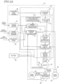
- control device 70 a specific structure of the control device 70, and a group of sensors that generate a signal usable to operate the control device 70, will be described in detail.
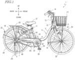
- the X axis, the Y axis and the Z axis of the electric assist bicycle 1 running on a flat road may not match the X axis, the Y axis and the Z axis of the electric assist bicycle 1 running on a slope.
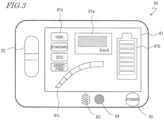
- the operation panel 60 includes a display panel 61, an assist mode operation switch 62, and a power source switch 65.
- the speed display area 61a displays the vehicle speed of the electric assist bicycle 1 by numerical figures.
- the vehicle speed of the electric assist bicycle 1 is detected by a speed sensor 35 provided on the front wheel 25.
- the power source switch 65 is a switch by which the power source of the electric assist bicycle 1 is switched on or off. The rider presses the power source switch 65 to switch the power source of the electric assist bicycle 1 on or off.
- the speaker 63 may be caused to generate an audio signal of a volume that is heard by people around the electric assist bicycle 1, or the head lamp 22 and the tail lamp 23 may be lit up or blinked. With such an arrangement, the people around the electric assist bicycle 1 recognize that the electric assist bicycle 1 is generating assist power larger than the usual assist power.
- the electric motor 53 In the case where the assist mode is "standard", the electric motor 53 generates assist power when, for example, the electric assist bicycle 1 is to start, is running on a flat road, or is running on an ascending slope. In the case where the assist mode is "high”, the electric motor 53 generates assist power when, for example, the electric assist bicycle 1 is to start, is running on a flat road, or is running on an ascending slope, like in the case where the assist mode is "standard”. In the case where the assist mode is "high”, the electric motor 53 generates larger assist power than in the case where the assist mode is "standard” in response to the same crank rotation output.
- the assist power in response to the crank rotation output is varied in accordance with the assist mode described above.
- the assist mode is switched to any one of four stages.
- the assist mode may be switched to any of three stages or less, or any of five stages or more.
- the magnitude of the human power (pedal force) of the rider applied to the pedal 55 is increased or decreased in accordance with the position of the pedal 55, namely, the rotation angle of the crankshaft 57.
- the increase or the decrease in the pedal force applied to the pedal 55 appears as increase or decrease in the torque generated at the crankshaft 57.
- the motive power that runs the electric assist bicycle 1 is increased or decreased. Therefore, the acceleration in the travel direction x of the electric assist bicycle 1 is increased or decreased in accordance with the increase or the decrease in the torque.
- FIG. 4 shows a state where a right pedal 55R of the electric assist bicycle 1, on which the rider puts his/her right foot, is located just above the crankshaft 57, whereas a left pedal 55L of the electric assist bicycle 1, on which the rider puts his/her left foot, is located just below the crankshaft 57.
- the rotation angle of the crankshaft 57 at this point is set as 0 degrees.
- the torque generated at the crankshaft 57 by the human power is minimum.
- the acceleration in the travel direction x is also minimum.
- FIG. 4 shows a state where the left pedal 55L is located to the front, in the horizontal direction, of the crankshaft 57, whereas the right pedal 55R is located to the rear, in the horizontal direction, of the crankshaft 57.
- the rotation angle of the crankshaft 57 at this point is set as 270 degrees.
- the torque generated at the crankshaft 57 by the human power is maximum.
- the acceleration in the travel direction x of the vehicle is also maximum.
- a peak of the ridge represents the maximum value of the torque in the zone.
- a bottom of the trough of the torque represents the minimum value of the torque in the zone.
- the zone between the ridge and the trough adjacent to each other includes the peak of the ridge and the bottom of the trough.
- the rider While the rider is pedaling the electric assist bicycle 1 on a flat road in the certain pedaling manner, the rider is considered to wish to run the electric assist bicycle 1 at an acceleration changing periodically as shown in FIG. 4 .
- the electric assist bicycle 1 is influenced by various external disturbances. For this reason, the acceleration changing periodically as shown in FIG. 4 may not be obtained.
- a headwind caused by the running of the electric assist bicycle 1, a wind meteorologically generated and/or a slope are all examples of the external disturbances.
- the present inventor conceived adjusting the assist power of the electric assist bicycle 1 such that while the rider is pedaling the electric assist bicycle 1 in the certain pedaling manner, the rider runs the electric assist bicycle 1 with the sense of acceleration changing periodically as shown in FIG. 4 regardless of whether there is any external disturbance or not.
- the "sense of acceleration” used in this specification refers to the sense of speed that the rider feels by increase or decrease in the speed in the travel direction while running the electric assist bicycle 1 with the acceleration changing periodically as shown in FIG. 4 .
- the "sense of acceleration” is different from the acceleration detected by the acceleration sensor 38. As described below, on a slope, the acceleration sensor 38 detects an acceleration in accordance with the inclination.
- FIG. 5A schematically shows a waveform of a value of the torque obtained based on the torque signal.
- the control device 70 calculates a target acceleration from the torque signal, and determines the magnitude of the assist power to be generated by the electric motor 53 such that the deviation between the target acceleration and the current acceleration is decreased.
- the value of the torque represented by the torque signal is a value directly indicating with what acceleration the rider wishes to drive the electric assist bicycle 1, and set a map or a function defining the correspondence between the torque signal and the target acceleration.
- the map or function may be used to determine the target acceleration uniquely from the value of the torque.
- FIG. 5A schematically shows a waveform of the target acceleration calculated based on the torque.
- the target acceleration is smaller; whereas as the value of the torque is larger, the target acceleration is larger.
- the value of the target acceleration may be increased or decreased in synchronization with the value of the torque.
- FIG. 5A schematically shows the acceleration in the travel direction x of the vehicle.
- the solid line represents a waveform of the acceleration signal that is output from the acceleration sensor 38
- the dashed line represents the waveform of the target acceleration.
- P-P(t) a difference between the ridge and the trough, adjacent to each other, of the acceleration at time t.
- the difference P-P(t) and a difference P-P(t+1) will be compared against each other.
- the acceleration value of the latter has a larger amplitude in the negative direction. Therefore, the deviation En(t+1) between the acceleration value and the target acceleration value at time (t+1) is relatively large.
- control device 70 determines the magnitude of the assist power to be generated by the electric motor 53 such that the deviation En(t+1) is decreased.
- the term "decreased” refers to, for example, "made 0 (zero)".
- the control device 70 After the electric assist bicycle 1 is subjected to the headwind, the control device 70 generates larger assist power. As a result, at time (t+2) , a deviation En(t+2) is converged to approximately 0. This indicates that the rider is subjected to the headwind but maintains the same acceleration as long as keeping on pedaling the electric assist bicycle 1 with the same pedal force (torque).
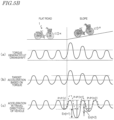
- FIG. 5B shows an example of motion of the electric assist bicycle 1 in the case where the rider receives, from a slope, a downward force parallel to the inclining surface as a load. It is assumed that the electric assist bicycle 1 runs on a flat road up to a certain time point and then, starts running on a slope at the timing represented by the dotted line parallel to the up-down direction of the figure.
- (b) and (c) of FIG. 5B respectively show the target acceleration and the current acceleration. In each of (b) and (c) of FIG.
- the waveform after the electric assist bicycle 1 starts running on the slope is provided as a waveform obtained as a result of removing, by a high-pass filter, a low-frequency component of the acceleration which is added in accordance with the slope. This process will be described below in detail.
- FIG. 5B schematically shows a waveform of a value of the torque obtained based on the torque signal.
- the rider rides the electric assist bicycle 1 in the certain pedaling manner on a flat road, but pedals the electric assist bicycle 1 with a larger pedal force immediately after the start of the slope.
- Such a manner of pedaling is common.
- a reason for this is that before and after the start of the slope, the rider expects that the speed will be decreased due to the ascending slope, and intuitively pedals the electric assist bicycle 1 strongly.
- (b) of FIG. 5B schematically shows a waveform of the target acceleration calculated based on the torque.
- the target acceleration is smaller; whereas as the value of the torque is larger, the target acceleration is larger. It is understood that in synchronization with the larger pedal force immediately after the start of the slope, the target acceleration is calculated to be larger than that before the start of the slope.
- FIG. 5B schematically shows the acceleration in the travel direction x of the vehicle.
- the solid line represents a waveform of the acceleration signal that is output from the acceleration sensor 38, and the dashed line represents the waveform of the target acceleration.
- the difference P-P(t) and the difference P-P(t+1) will be compared against each other.
- the acceleration value of the latter has a larger amplitude in the negative direction. Therefore, the deviation En(t+1) between the acceleration value and the target acceleration value at time (t+1) is relatively large.
- the control device 70 determines the magnitude of the assist power to be generated by the electric motor 53 such that the deviation En(t+1) is decreased.
- the term "decreased” refers to, for example, "made 0 (zero)".
- control device 70 will be described with reference to FIG. 2A again, and then, an operation performed by the control device 70 will be described.
- the averaging circuit 78 is a digital filtering circuit that smooths a detection signal regarding each of the axial directions that is output from the acceleration sensor 38.
- the averaging circuit 78 may, for example, calculate a moving average of a plurality of detection signals to smooth the detection signals. Another smoothing algorithm may be used.
- the averaging circuit 78 is provided. Nonetheless, according to the present invention, it is not indispensable to provide the averaging circuit 78.
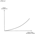
- the target acceleration calculation block 72 receives a torque signal from the torque sensor 41, and refers to an acceleration calculation rule 77a stored in advance on the storage block 77 described below to calculate the target acceleration from the torque signal.
- the correspondence between torque signal and the target acceleration is represented as a nonlinear continuous function. This is an example.
- the correspondence between torque signal and the target acceleration may be represented as a linear continuous function, or may be represented by a map or a table that associates the signal value of the torque signal and the target acceleration in a one-to-one manner.
- FIG. 6 may be extended.
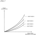
- a different function, map or table may be selected in accordance with the selected assist mode.
- FIG. 7 shows the relationship between the pedal force provided by the human (torque signal) and the target acceleration that is defined for each of the N pieces of selectable assist modes. It is assumed that the assist ratio is lowest in assist mode 1 and is highest in assist mode N. In the example shown in FIG. 7 , as the assist mode is of a higher assist ratio, a larger target acceleration may be set for the same pedal force.
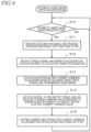
- the motor electric current command value calculation block 74 calculates the motor electric current command value, based on which subsequent processes are to be performed.
- the magnitude of the torque to be generated by the electric motor 53 is in proportion to the level of the electric current to flow in the electric motor 53. Once the level of the electric current that is to flow in the electric motor 53 is determined, the magnitude of the torque to be generated is determined uniquely. Namely, determining the motor electric current command value is determining the magnitude of the torque to be generated by the electric motor 53.
- the transmission gear range sensor 48 detects the transmission gear range of the transmission included in the power transmission mechanism 31.
- the magnitude of the assist power to be applied to the ground by the rear wheel 26 changes in accordance with the level of the transmission gear range. Therefore, the output value of the transmission gear range sensor 48 is also considered to be one of the basic parameters usable to calculate the motor electric current command value.
- the motor electric current command value calculation block 74 further receives speed data from the speed sensor 35.
- the motor electric current command value calculation block 74 finds the motor electric current command value such that, for example, the torque to be generated at the driving shaft of the rear wheel 26 by the pedal force and the torque to be generated at the driving shaft of the rear wheel 26 by the driving motor 53 are equal to each other (assist ratio is 1:1).
- the motor electric current command value may be found by use of, for example, a predefined "table representing the relationship between the human power torque and the motor electric current command value". In this process, the motor electric current command value calculation block 74 calculates the motor electric current command value further in consideration of the deceleration ratio of the decelerator that decelerates the rotation of the electric motor 53.
- the motor electric current command value correction block 75 receives the motor electric current command value calculated by the motor electric current command value calculation block 74, the value of the target acceleration that is output from the target acceleration calculation block 72, and the value of the acceleration sensor 38 (value of the detected acceleration) that is output from the high-pass filter 73.
- the motor electric current command value correction block 75 corrects the motor electric current command value such that the detected acceleration matches the target acceleration.
- the motor electric current command value correction block 75 determines the motor torque Fm, corresponding to the assist power to be generated, by the electric motor 53 by the following expression.
- Fm t Kp ⁇ e t + Ki ⁇ ⁇ 0 l e ⁇ d ⁇ + Kd ⁇ de t dt .
- the second term of the right side represents a calculation regarding the integration element (integration control calculation).
- proportion control calculation the amount of operation is decreased as the current value is made closer to the target value. Therefore, the deviation remains.
- the integration control calculation is used to further decrease such a residual deviation.
- the residual deviation is temporally accumulated. When the residual deviation reaches a certain magnitude, the amount of operation may be increased to further decrease the residual deviation.
- the motor electric current command value correction block 75 determines the torque of a magnitude in proportion to the accumulated value of the residual deviation.
- the motor electric current command value correction block 76 corrects the motor electric current command value in accordance with the vehicle speed.
- a predetermined value or higher e.g. 10 km per hour or higher
- the upper limit of the assist ratio is gradually decreased.
- the assist ratio is 1:0, namely, the assist output is zero.
- the motor electric current command value correction block 76 determines the ratio of such gradual decrease by use of, for example, a predefined "table representing the relationship between the vehicle speed and the ratio of gradual decrease".
- the motor electric current command value is multiplied by the ratio of gradual decrease, so that the torque to be generated by the electric motor 53 is gradually decreased.
- the change in the ratio of gradual decrease may be linear or curved.
- the motor electric current command value correction block 76 also corrects the motor electric current command value in accordance with the rotation speed of the crankshaft 57. While, for example, the electric assist bicycle 1 is running at a low speed immediately before stopping, the feel of driving varies in accordance with when the generation of the assist power is stopped. For example, there is a case where the feel of driving is improved by generating slight assist power continuously even though the pedal force is substantially zero. In such a case, the rotation speed of the crankshaft 57 may be referred to, so that it is checked whether or not the rider intends to drive. While the crankshaft 57 is moving, namely, the rider is pedaling, the assist power is generated; and when the crankshaft 57 is stopped, the generation of the assist power is stopped. In this manner, the feel of driving is improved.
- the motor electric current command value correction block 76 outputs the motor electric current command value to the motor driving circuit 79.
- the motor driving circuit 79 supplies the electric motor 53 with an electric current of a level in accordance with the motor electric current command value.
- the motor electric current command value received by the motor driving circuit 79 represents the level of the electric current to be actually caused to flow in the electric motor 53.
- the motor electric current command value is considered to represent the target motor electric current value.
- the motor driving circuit 79 monitors and controls the amount of the electric current such that the electric current of the level indicated by the target motor electric current value flows. It is preferred that the control performed in this process is feedback control. In this embodiment, the motor driving circuit 79 performs PID control as the feedback control.
- the PID control is a well-known control method represented by expression 1 shown above. Thus, the details of the process will not be described.
- the motor driving circuit 79 may use any control method as long as the level of the electric current actually flowing may be controlled to match the motor electric current command value.
- the driving unit 51 includes an electric current sensor 47 in order to monitor the electric current.
- the electric current sensor 47 detects a value of the electric current flowing in the electric motor 53 and outputs the value to the motor driving circuit 79.
- the motor driving circuit 79 uses the output signal of the electric current sensor 47 to perform the feedback control.
- the electric currents of sine waveforms that are shifted by 120 degrees with respect to each other flow.
- the "value of the electric current” generally refers to the amplitude of the waveform, and may be represented as the difference P-P (Peak to Peak) between the maximum value and the minimum value of the electric current.
- a method for calculating the difference P-P from an actual measurement value of the electric current is well-known.
- the motor driving circuit 79 may substitute two actual measurement values of the electric currents, detected by the electric current sensor 47, into a predetermined calculation expression to find the difference P-P.
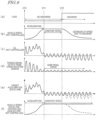
- the vertical axis represents the magnitude of the load received by the electric assist bicycle 1 and the rider thereof.
- the vertical axis represents the vehicle speed in the travel direction of the vehicle.
- FIG. 9(b) shows the vehicle speed in the case where the process according to this embodiment is not performed.
- the vertical axis represents the acceleration signal Gx in the x-axis direction that is output from the acceleration sensor 38.
- FIG. 9(c) shows a waveform of the vehicle acceleration signal Gx in the x-axis direction in the case where the control according to this embodiment is not performed.
- FIG. 10 shows waveforms of various signals when a load change occurs while the rider is pedaling the electric assist bicycle 1.
- the load change is assumed to be caused when the flat road is changed to a slope.
- the situation shown in FIG. 10 corresponds to FIG. 5B referred to above.
- FIG. 10(c) shows a waveform of the vehicle acceleration signal Gx in the x-axis direction in the case where the control according to this embodiment is not performed.
- the vertical axis represents the acceleration signal having a low-frequency component removed by the high-pass filter 73.
- the vertical axis represents the torque signal that is output from the crank rotation sensor 42 in the case where the process according to this embodiment is not performed.
- the vertical axis represents the torque signal that is output from the crank rotation sensor 42 in the case where the process according to this embodiment is performed.
- the vertical axis represents the target acceleration (solid line) found from the torque signal shown in FIG. 10(f) . It should be noted that this target acceleration does not include a signal component that is caused by the slope and is added to the output of the acceleration sensor 38.
- the vertical axis represents the vehicle speed (solid line) in the case where the control according to this embodiment is performed.
- FIG. 10(h) also shows, with the dashed line, a waveform of the vehicle speed in the x-axis direction in the case where the control according to this embodiment is not performed.
- FIG. 11A will be referred to.
- the electric assist bicycle 1 is the point mass that is present at the position of the gravitational center thereof, the gravitational force M.G is applied to the electric assist bicycle 1 in a vertically downward direction.
- the acceleration sensor 38 is constantly influenced by the gravitational force. Therefore, in the state where the electric assist bicycle 1 is still, the acceleration sensor 38 detects the gravitational acceleration G acting in the vertically downward direction (e.g., negative direction of the Z-axis direction).
- the situation is the same in FIG. 11B .
- the electric assist bicycle 1 In the state of being still on a slope, the electric assist bicycle 1 is still against a component, of the gravitational force, in a direction going down the slope (against M ⁇ G ⁇ sin ⁇ 0 ) . Where the direction going down the slope is negative, the acceleration in this state is -G ⁇ sin ⁇ 0 .
- the electric assist bicycle 1 still on the slope is accelerating at a magnitude of G ⁇ sin ⁇ 0 in a direction going up the slope so as to counteract the acceleration in the direction going down the slope (so as to counteract G ⁇ sin ⁇ 0 ). Namely, the acceleration is +G ⁇ sin ⁇ 0 .
- the acceleration +G ⁇ sin ⁇ 0 is constantly overlapped.
- FIG. 12 shows the acceleration signal as a target for the case where the low-frequency component is not removed by the high-pass filter 73 (solid line).
- FIG. 12 also shows the acceleration signal in the case where the process according to this embodiment is not performed (dashed line).
- the acceleration signal having the low-frequency component removed by the high-pass filter 73 is used.
- the result is the same even in the case where the target acceleration value is set as represented by the solid line in FIG. 12 .
- the use of the high-pass filter 73 realizes the same process as that in the case where the headwind or the like occurs, regardless of whether the electric assist bicycle 1 is running on a slope or not.
- an illustrative electric assist system (driving unit 51) according to the present invention is usable for an electric assist vehicle (electric assist bicycle 1) including the pedal 55.
- the electric assist system includes the crankshaft 57 rotatable by human power of a rider applied to the pedal; the torque sensor 41 outputting a torque signal in accordance with a magnitude of a torque generated at the crankshaft; the electric motor 53 generating assist power assisting the human power of the rider; the acceleration sensor 38 outputting an acceleration signal in accordance with a current acceleration in a travel direction of the electric assist vehicle; and the control device 70 receiving the torque signal and the acceleration signal and determining a magnitude of the assist power to be generated by the electric motor.
- the control device calculates a target acceleration from the torque signal based on a rule prepared in advance, and determines the magnitude of the assist power to be generated by the electric motor such that a deviation between the target acceleration and the current acceleration is decreased.
- the magnitude of the human power of the rider applied to the pedal changes in accordance with the position of the pedal while the rider is rotating the pedal. Therefore, the acceleration in the travel direction of the electric assist bicycle changes in accordance with the position of the pedal while the rider is rotating the pedal.
- the electric assist system changes the magnitude of the assist power to be generated by the electric motor such that the deviation between the target acceleration found from the pedal force of the rider and the current acceleration of the vehicle is decreased. Even if a load is applied during the running, the pedal force of the rider is considered to represent the sense of acceleration desired by the rider. Therefore, the target acceleration is set based on the pedal force, and the current acceleration of the vehicle is controlled to be made closer to the target acceleration. With such an arrangement, the rider may run the electric assist vehicle with an appropriate magnitude of assist power in accordance with the load during the running.
- control device 70 may determine the magnitude of the assist power to be generated by the electric motor 53 such that the deviation is made closer to 0.
- the ability of making the acceleration closer to the target acceleration may be improved.
- control device 70 includes the storage device 77 holding the rule prepared in advance.
- control device 70 includes the high-pass filter 73 transmitting a high-frequency component of a predefined frequency or higher that is included in the received acceleration signal.
- control device 70 includes the high-pass filter 73 transmitting a high-frequency component of 5 Hz or higher.
- the torque signal changes in accordance with the rotation of the crankshaft that is associated with an operation of the rider rotating the pedal
- the acceleration signal changes in accordance with the operation of the rider rotating the pedal and an external disturbance applied to the electric assist vehicle (electric assist bicycle 1)
- the control device 70 calculates the target acceleration from the torque signal, calculates the acceleration from the acceleration signal, and determines the magnitude of the assist power to be generated by the electric motor 53.
- the electric assist system (driving unit 51) further includes the motor driving circuit 79 outputting, to the electric motor, an electric current having at least one of an amplitude, a frequency and a flow direction controlled in accordance with a command value.
- the control device 70 outputs, to the motor driving circuit 79, a command value usable to cause an electric current that is in accordance with the determined magnitude of the assist power to flow.
- an appropriate magnitude of assist power may be generated such that the target acceleration in accordance with the pedal force during the running is obtained.
- An electric assist vehicle (electric assist bicycle 1) according to an illustrative embodiment of the present invention includes the above-described electric assist system (driving unit 51).
- the electric assist vehicle includes the front wheel 25 and the rear wheel 26; and the power transmission mechanism 31 transmitting the human power of the rider and the assist power to the rear wheel.
- the electric assist vehicle including the electric assist system according to an illustrative embodiment of the present invention may generate appropriate magnitude of assist power such that the target acceleration in accordance with the pedal force during the running is obtained.
- the present invention is especially useful for a vehicle that includes an acceleration sensor and is driven by human power assisted by assist power.
Landscapes
- Engineering & Computer Science (AREA)
- Transportation (AREA)
- Mechanical Engineering (AREA)
- Power Engineering (AREA)
- Chemical & Material Sciences (AREA)
- Combustion & Propulsion (AREA)
- Electric Propulsion And Braking For Vehicles (AREA)
Claims (16)
- Système d'assistance électrique (51) utilisable pour un véhicule à assistance électrique (1) incluant une pédale (55), le système d'assistance électrique (51) comprenant :une manivelle (57) mobilisable en rotation par une puissance musculaire d'un cycliste appliquée à la pédale (55) ;un capteur de couple (41) produisant un signal de couple conformément à une amplitude d'un couple généré au niveau de la manivelle (57) ;un moteur électrique (53) générant une puissance d'assistance assistant la puissance musculaire du cycliste ;un capteur d'accélération (38) produisant un signal d'accélération conformément à une accélération courante dans une direction de déplacement (x) du véhicule à assistance électrique (1) ; etun dispositif de commande (70) recevant le signal de couple et le signal d'accélération et déterminant une amplitude de la puissance d'assistance à générer par le moteur électrique (53),dans lequel le dispositif de commande (70) calcule une accélération cible à partir du signal de couple selon une règle préparée à l'avance, et détermine l'amplitude de la puissance d'assistance à générer par le moteur électrique (53) de sorte qu'une dérive entre l'accélération cible et l'accélération courante soit diminuée, caractérisé en ce que,au cours d'une période temporelle dans laquelle le cycliste fait tourner la pédale (55) pour effectuer une rotation de la manivelle (57), le capteur de couple (41) et le capteur d'accélération (38) produisent respectivement un signal de couple et un signal d'accélération continuellement, etle dispositif de commande (70) détermine l'amplitude de la puissance d'assistance à générer par le moteur électrique (53) temporellement continuellement.
- Le système d'assistance électrique (51) de la revendication 1, dans lequel le dispositif de commande (70) exécute un contrôle PID pour déterminer l'amplitude de la puissance d'assistance à générer par le moteur électrique (53) et ainsi pour diminuer la dérive.
- Le système d'assistance électrique (51) de la revendication 2, dans lequel une dérive courante à un moment courant t est représentée comme E(t), et des gains de réinjection d'un élément proportionnel, un élément différentiel et un élément d'intégration du système de commande de puissance d'assistance sont respectivement représentés comme Kp, Kd et Ki,
le dispositif de commande (70) détermine un couple de moteur Fm, correspondant à la puissance d'assistance à générer, par le moteur électrique (53) par :
- Le système d'assistance électrice (51) de l'une quelconque des revendications 1 à 3, dans lequel le dispositif de commande (70) détermine l'amplitude de la puissance d'assistance à générer par le moteur électrique (53) de sorte que la dérive soit plus proche de 0.
- Le système d'assistance électrique (51) de l'une quelconque des revendications 1 à 4, dans lequel le dispositif de commande (70) stocke, à l'avance, une table associant une valeur de commande pour un courant électrique qui est appelé à circuler dans le moteur électrique (53) et une amplitude d'un couple de moteur correspondant à la puissance d'assistance à générer par le moteur électrique (53) l'une à l'autre, et fait référence à la table pour déterminer la valeur de commande pour le courant électrique requis pour générer le couple de moteur.
- Le système d'assistance électrique (51) de la revendication 4, dans lequel le dispositif de commande (70) stocke, à l'avance, une table associant une valeur de commande pour un courant électrique qui est appelé à circuler dans le moteur électrique (53) et une amplitude d'un couple de moteur l'une à l'autre pour chacune de plages d'amplitudes de la dérive, et fait référence à la table pour déterminer la valeur de commande pour le courant électrique requis pour générer le couple de moteur.
- Le système d'assistance électrique (51) de la revendication 2, dans lequel une dérive courante à un moment courant t est représentée comme E(t), et des gains de réinjection utilisables pour trouver une valeur de commande pour un courant électrique à partir d'un terme de proportion, d'un terme d'intégration et d'un terme différentiel relatifs à une dérive résiduelle sont respectivement représentés comme Kp', Kd' et Ki',
le dispositif de commande (70) détermine la valeur de commande lm, pour le courant électrique qui est appelé à circuler dans le moteur électrique (53), par :
- Le système d'assistance électrique (51) de l'une quelconque des revendications 1 à 7, dans lequel le dispositif de commande (70) inclut un dispositif de stockage (77) conservant la règle préparée à l'avance.
- Le système d'assistance électrique (51) de la revendication 8, dans lequel la règle est une association ou une fonction définissant la correspondance entre le signal de couple et l'accélération cible.
- Le système d'assistance électrique (51) de la revendication 9, dans lequel la fonction est une fonction non linéaire ou une fonction linéaire.
- Le système d'assistance électrique (51) de l'une quelconque des revendications 1 à 10, dans lequel le dispositif de commande (70) inclut un filtre passe-haut (73) transmettant un composant haute fréquence d'une fréquence prédéfinie ou supérieure qui est incluse dans le signal d'accélération reçu.
- Le système d'assistance électrique (51) de la revendication 11, dans lequel le dispositif de commande (70) inclut un filtre passe-haut (73) transmettant un composant haute fréquence de 5 Hz ou supérieur.
- Le système d'assistance électrique (51) de l'une quelconque des revendications 1 à 12, dans lequel au cours d'une période temporelle dans laquelle le cycliste fait tourner la pédale (55) pour effectuer une rotation de la manivelle (57), le signal de couple change conformément à la rotation de la manivelle (57) qui est associée à une opération du cycliste faisant tourner la pédale (55),le signal d'accélération change conformément à l'opération du cycliste faisant tourner la pédale (55) et à une perturbation extérieure appliquée au véhicule à assistance électrique (1), etle dispositif de commande (70), selon un minutage prédéfini, calcule l'accélération cible à partir du signal de couple, calcule l'accélération à partir du signal d'accélération et détermine l'amplitude de la puissance d'assistance à générer par le moteur électrique (53).
- Le système d'assistance électrique (51) de l'une quelconque des revendications 1 à 13, comprenant en outre un circuit d'entraînement de moteur (79) produisant, vers le moteur électrique (53), un courant électrique présentant au moins une d'une amplitude, d'une fréquence et d'une direction de circulation contrôlées conformément à une valeur de commande,
dans lequel le dispositif de commande (70) produit, vers le circuit d'entraînement de moteur (79), une valeur de commande utilisable pour entraîner une circulation d'un courant électrique qui est conforme à l'amplitude déterminée de la puissance d'assistance. - Véhicule à assistance électrique (1), comprenant le système d'assistance électrique (51) de la revendication 14.
- Le véhicule à assistance électrique (1) de la revendication 15, comprenant en outre :une roue avant (25) et d'une roue arrière (26) ; etun mécanisme de transmission de puissance (31) transmettant la puissance musculaire du cycliste et la puissance d'assistance à la roue arrière (26).
Applications Claiming Priority (2)
| Application Number | Priority Date | Filing Date | Title |
|---|---|---|---|
| JP2016255871 | 2016-12-28 | ||
| PCT/JP2017/034147 WO2018123161A1 (fr) | 2016-12-28 | 2017-09-21 | Système d'assistance électrique et véhicule à assistance électrique |
Publications (3)
| Publication Number | Publication Date |
|---|---|
| EP3564111A1 EP3564111A1 (fr) | 2019-11-06 |
| EP3564111A4 EP3564111A4 (fr) | 2020-01-15 |
| EP3564111B1 true EP3564111B1 (fr) | 2024-07-10 |
Family
ID=62707166
Family Applications (1)
| Application Number | Title | Priority Date | Filing Date |
|---|---|---|---|
| EP17888447.4A Active EP3564111B1 (fr) | 2016-12-28 | 2017-09-21 | Système d'assistance électrique et véhicule à assistance électrique |
Country Status (6)
| Country | Link |
|---|---|
| US (1) | US20190299797A1 (fr) |
| EP (1) | EP3564111B1 (fr) |
| JP (1) | JP6805269B2 (fr) |
| CN (1) | CN110121460B (fr) |
| TW (1) | TWI666142B (fr) |
| WO (1) | WO2018123161A1 (fr) |
Families Citing this family (22)
| Publication number | Priority date | Publication date | Assignee | Title |
|---|---|---|---|---|
| US20180334221A1 (en) * | 2017-05-16 | 2018-11-22 | Wen-Sung Lee | Power generation device for bicycle |
| JP6916047B2 (ja) * | 2017-06-16 | 2021-08-11 | 株式会社シマノ | 自転車用制御装置 |
| JP7060974B2 (ja) * | 2018-02-07 | 2022-04-27 | ヤマハ発動機株式会社 | 電動補助自転車及びその駆動システム |
| JP7055717B2 (ja) * | 2018-07-30 | 2022-04-18 | 株式会社小野測器 | 自転車試験装置 |
| EP3674130B1 (fr) * | 2018-12-26 | 2023-10-18 | ZUMA Innovation, S.L. | Véhicule électrique avec système de contrôle basé sur stimuli au conducteur |
| TWI770430B (zh) * | 2019-10-24 | 2022-07-11 | 英屬開曼群島商睿能創意公司 | 電動助力車、傳動裝置及控制方法 |
| DE102020200432B4 (de) | 2019-12-09 | 2023-08-10 | Robert Bosch Gesellschaft mit beschränkter Haftung | Verfahren zur Steuerung eines Elektromotors eines Elektrofahrrads zum Antrieb des Elektrofahrrads, Steuergerät und Elektrofahrrad |
| US11225301B2 (en) * | 2019-12-18 | 2022-01-18 | Honda Motor Co., Ltd. | Providing movement assistance to electric cycle on inclined structures |
| JP7492825B2 (ja) * | 2019-12-27 | 2024-05-30 | 株式会社シマノ | 人力駆動車用の制御装置 |
| CN112208356B (zh) * | 2020-10-16 | 2022-04-15 | 安徽江淮汽车集团股份有限公司 | 扭矩控制方法、设备、存储介质及装置 |
| DE102020215569B4 (de) | 2020-12-09 | 2023-12-28 | Robert Bosch Gesellschaft mit beschränkter Haftung | Steuerungsverfahren für ein Elektrofahrrad, Steuergerät und Elektrofahrrad |
| NO346194B1 (en) * | 2021-01-14 | 2022-04-11 | Ca Tech Systems As | Pedally propelled vehicle gear system and method for operating such system |
| JP2024507369A (ja) * | 2021-02-22 | 2024-02-19 | フォールブルック インテレクチュアル プロパティー カンパニー エルエルシー | 乗り手の所望の乗車目標を達成するためのモータアシスト自転車の自動制御 |
| CN113815431B (zh) * | 2021-10-14 | 2022-04-15 | 河南嘉晨智能控制股份有限公司 | 一种工业车辆驾驶感改善方法 |
| CN114510005B (zh) * | 2022-01-07 | 2024-06-25 | 上海钧正网络科技有限公司 | 骑行设备的控制方法、装置和骑行设备 |
| CN116552692A (zh) * | 2022-01-27 | 2023-08-08 | 常州瑞阳电装有限公司 | 电动脚踏车、电动脚踏车的控制系统及其控制方法 |
| DE112022007138T5 (de) * | 2022-04-26 | 2025-02-27 | Gkn Automotive Limited | Antriebssystem |
| FR3148407A1 (fr) * | 2023-05-02 | 2024-11-08 | Cixi | Dispositif de commande d’au moins un moteur électrique d’un véhicule |
| CN119058872A (zh) * | 2023-06-01 | 2024-12-03 | 台达电子工业股份有限公司 | 电动辅助自行车的控制系统及控制方法 |
| DE102023115977A1 (de) * | 2023-06-19 | 2024-12-19 | Brose Antriebstechnik GmbH & Co. Kommanditgesellschaft, Berlin | Antriebssystem für ein Elektrofahrrad mit einer Filtereinheit und Verfahren zur Ermittlung mindestens eines Betriebsparameters |
| CN117341884A (zh) * | 2023-11-01 | 2024-01-05 | 上海派智能源股份有限公司 | 电动自行车及其控制系统 |
| CN121508395B (zh) * | 2026-01-13 | 2026-03-24 | 常州锝莱电机有限公司 | 一种实现电机宽转速区间最优效率的在线寻优控制系统 |
Citations (2)
| Publication number | Priority date | Publication date | Assignee | Title |
|---|---|---|---|---|
| EP0926059B1 (fr) * | 1997-12-24 | 2008-10-08 | Matsushita Electric Industrial Co., Ltd. | Véhicule avec moteur auxiliaire et procédé de commande |
| DE102014219595A1 (de) * | 2014-09-26 | 2016-03-31 | Continental Teves Ag & Co. Ohg | Längsdynamiksteuerung am Pedelec |
Family Cites Families (16)
| Publication number | Priority date | Publication date | Assignee | Title |
|---|---|---|---|---|
| JP3641055B2 (ja) | 1996-02-22 | 2005-04-20 | ヤマハ発動機株式会社 | 電動補助自転車 |
| DE19755309A1 (de) * | 1997-12-12 | 1999-06-17 | Rolf Dr Rer Nat Strothmann | Steuerung für auf Muskel- und Motorkraft gestützte Antriebe |
| JP4369589B2 (ja) * | 2000-03-01 | 2009-11-25 | 本田技研工業株式会社 | 電動自転車 |
| JP4016714B2 (ja) * | 2002-05-21 | 2007-12-05 | 松下電器産業株式会社 | 補助動力装置付き自転車 |
| JP2004015925A (ja) * | 2002-06-07 | 2004-01-15 | Mitsuba Corp | ブラシレスモータ制御方法 |
| JP4024091B2 (ja) * | 2002-06-21 | 2007-12-19 | 松下電器産業株式会社 | 補助動力付き車輌 |
| GB0307038D0 (en) * | 2003-03-27 | 2003-04-30 | Torotrak Dev Ltd | System and method for controlling a continuously variable transmission |
| JP5922586B2 (ja) * | 2010-12-22 | 2016-05-24 | マイクロスペース株式会社 | モータ駆動制御装置 |
| DE102012206003A1 (de) * | 2012-04-12 | 2013-10-17 | Robert Bosch Gmbh | Verfahren zur Regelung eines pedalgetriebenen Fahrzeugs und Regelungsvorrichtung |
| JP5602186B2 (ja) * | 2012-05-28 | 2014-10-08 | マイクロスペース株式会社 | モータ駆動制御装置 |
| KR20140038050A (ko) * | 2012-09-19 | 2014-03-28 | 주식회사 만도 | 전기 자전거 및 그 제어방법 |
| KR20140038048A (ko) * | 2012-09-19 | 2014-03-28 | 주식회사 만도 | 전기 자전거 및 그 제어방법 |
| EP3009295B1 (fr) * | 2013-06-14 | 2024-08-07 | Microspace Corporation | Dispositif de commande d'entraînement de moteur |
| FR3018057B1 (fr) * | 2014-02-28 | 2018-06-29 | Commissariat A L'energie Atomique Et Aux Energies Alternatives | Assistance au deplacement d'un objet roulant par un asservissement utilisant l'acceleration de l'objet roulant |
| JP6453097B2 (ja) * | 2015-02-18 | 2019-01-16 | 日本電産コパル株式会社 | 車両の電動アシスト制御システム及び車両 |
| CN104935226A (zh) * | 2015-05-12 | 2015-09-23 | 合肥工业大学 | 一种电动自平衡独轮车的控制系统及其控制方法 |
-
2017
- 2017-09-21 EP EP17888447.4A patent/EP3564111B1/fr active Active
- 2017-09-21 WO PCT/JP2017/034147 patent/WO2018123161A1/fr not_active Ceased
- 2017-09-21 CN CN201780081176.6A patent/CN110121460B/zh active Active
- 2017-09-21 JP JP2018558814A patent/JP6805269B2/ja active Active
- 2017-10-25 TW TW106136776A patent/TWI666142B/zh active
-
2019
- 2019-06-18 US US16/443,923 patent/US20190299797A1/en active Pending
Patent Citations (2)
| Publication number | Priority date | Publication date | Assignee | Title |
|---|---|---|---|---|
| EP0926059B1 (fr) * | 1997-12-24 | 2008-10-08 | Matsushita Electric Industrial Co., Ltd. | Véhicule avec moteur auxiliaire et procédé de commande |
| DE102014219595A1 (de) * | 2014-09-26 | 2016-03-31 | Continental Teves Ag & Co. Ohg | Längsdynamiksteuerung am Pedelec |
Also Published As
| Publication number | Publication date |
|---|---|
| JPWO2018123161A1 (ja) | 2019-10-31 |
| TW201823091A (zh) | 2018-07-01 |
| US20190299797A1 (en) | 2019-10-03 |
| JP6805269B2 (ja) | 2020-12-23 |
| EP3564111A1 (fr) | 2019-11-06 |
| EP3564111A4 (fr) | 2020-01-15 |
| TWI666142B (zh) | 2019-07-21 |
| WO2018123161A1 (fr) | 2018-07-05 |
| CN110121460B (zh) | 2021-06-01 |
| CN110121460A (zh) | 2019-08-13 |
Similar Documents
| Publication | Publication Date | Title |
|---|---|---|
| EP3564111B1 (fr) | Système d'assistance électrique et véhicule à assistance électrique | |
| US11440618B2 (en) | Electric assist system and electric assist vehicle | |
| US11577615B2 (en) | Electric assist system and electric assist vehicle | |
| EP3564109B1 (fr) | Système d'assistance électrique et véhicule à assistance électrique | |
| CN107651095B (zh) | 电力辅助自行车及其驱动系统 | |
| TWI764773B (zh) | 自行車用控制裝置 | |
| JP2019064353A (ja) | 自転車用制御装置 | |
| JP7171953B2 (ja) | 電動補助システムおよび電動補助車両 |
Legal Events
| Date | Code | Title | Description |
|---|---|---|---|
| STAA | Information on the status of an ep patent application or granted ep patent |
Free format text: STATUS: THE INTERNATIONAL PUBLICATION HAS BEEN MADE |
|
| PUAI | Public reference made under article 153(3) epc to a published international application that has entered the european phase |
Free format text: ORIGINAL CODE: 0009012 |
|
| STAA | Information on the status of an ep patent application or granted ep patent |
Free format text: STATUS: REQUEST FOR EXAMINATION WAS MADE |
|
| 17P | Request for examination filed |
Effective date: 20190724 |
|
| AK | Designated contracting states |
Kind code of ref document: A1 Designated state(s): AL AT BE BG CH CY CZ DE DK EE ES FI FR GB GR HR HU IE IS IT LI LT LU LV MC MK MT NL NO PL PT RO RS SE SI SK SM TR |
|
| AX | Request for extension of the european patent |
Extension state: BA ME |
|
| A4 | Supplementary search report drawn up and despatched |
Effective date: 20191212 |
|
| RIC1 | Information provided on ipc code assigned before grant |
Ipc: B62M 6/45 20100101AFI20191206BHEP |
|
| DAV | Request for validation of the european patent (deleted) | ||
| DAX | Request for extension of the european patent (deleted) | ||
| STAA | Information on the status of an ep patent application or granted ep patent |
Free format text: STATUS: EXAMINATION IS IN PROGRESS |
|
| 17Q | First examination report despatched |
Effective date: 20200924 |
|
| REG | Reference to a national code |
Ref country code: DE Free format text: PREVIOUS MAIN CLASS: B62M0006450000 Ref country code: DE Ref legal event code: R079 Ref document number: 602017083276 Country of ref document: DE Free format text: PREVIOUS MAIN CLASS: B62M0006450000 Ipc: B60L0015200000 |
|
| RIC1 | Information provided on ipc code assigned before grant |
Ipc: B60L 50/20 20190101ALI20210823BHEP Ipc: B62M 6/45 20100101ALI20210823BHEP Ipc: B60L 15/20 20060101AFI20210823BHEP |
|
| GRAP | Despatch of communication of intention to grant a patent |
Free format text: ORIGINAL CODE: EPIDOSNIGR1 |
|
| STAA | Information on the status of an ep patent application or granted ep patent |
Free format text: STATUS: GRANT OF PATENT IS INTENDED |
|
| INTG | Intention to grant announced |
Effective date: 20240507 |
|
| GRAS | Grant fee paid |
Free format text: ORIGINAL CODE: EPIDOSNIGR3 |
|
| GRAA | (expected) grant |
Free format text: ORIGINAL CODE: 0009210 |
|
| STAA | Information on the status of an ep patent application or granted ep patent |
Free format text: STATUS: THE PATENT HAS BEEN GRANTED |
|
| AK | Designated contracting states |
Kind code of ref document: B1 Designated state(s): AL AT BE BG CH CY CZ DE DK EE ES FI FR GB GR HR HU IE IS IT LI LT LU LV MC MK MT NL NO PL PT RO RS SE SI SK SM TR |
|
| REG | Reference to a national code |
Ref country code: CH Ref legal event code: EP |
|
| REG | Reference to a national code |
Ref country code: DE Ref legal event code: R096 Ref document number: 602017083276 Country of ref document: DE |
|
| REG | Reference to a national code |
Ref country code: LT Ref legal event code: MG9D |
|
| REG | Reference to a national code |
Ref country code: NL Ref legal event code: MP Effective date: 20240710 |
|
| PG25 | Lapsed in a contracting state [announced via postgrant information from national office to epo] |
Ref country code: PT Free format text: LAPSE BECAUSE OF FAILURE TO SUBMIT A TRANSLATION OF THE DESCRIPTION OR TO PAY THE FEE WITHIN THE PRESCRIBED TIME-LIMIT Effective date: 20241111 |
|
| REG | Reference to a national code |
Ref country code: AT Ref legal event code: MK05 Ref document number: 1701768 Country of ref document: AT Kind code of ref document: T Effective date: 20240710 |
|
| PG25 | Lapsed in a contracting state [announced via postgrant information from national office to epo] |
Ref country code: NL Free format text: LAPSE BECAUSE OF FAILURE TO SUBMIT A TRANSLATION OF THE DESCRIPTION OR TO PAY THE FEE WITHIN THE PRESCRIBED TIME-LIMIT Effective date: 20240710 |
|
| PG25 | Lapsed in a contracting state [announced via postgrant information from national office to epo] |
Ref country code: PT Free format text: LAPSE BECAUSE OF FAILURE TO SUBMIT A TRANSLATION OF THE DESCRIPTION OR TO PAY THE FEE WITHIN THE PRESCRIBED TIME-LIMIT Effective date: 20241111 Ref country code: NL Free format text: LAPSE BECAUSE OF FAILURE TO SUBMIT A TRANSLATION OF THE DESCRIPTION OR TO PAY THE FEE WITHIN THE PRESCRIBED TIME-LIMIT Effective date: 20240710 |
|
| PG25 | Lapsed in a contracting state [announced via postgrant information from national office to epo] |
Ref country code: NO Free format text: LAPSE BECAUSE OF FAILURE TO SUBMIT A TRANSLATION OF THE DESCRIPTION OR TO PAY THE FEE WITHIN THE PRESCRIBED TIME-LIMIT Effective date: 20241010 |
|
| PG25 | Lapsed in a contracting state [announced via postgrant information from national office to epo] |
Ref country code: GR Free format text: LAPSE BECAUSE OF FAILURE TO SUBMIT A TRANSLATION OF THE DESCRIPTION OR TO PAY THE FEE WITHIN THE PRESCRIBED TIME-LIMIT Effective date: 20241011 Ref country code: FI Free format text: LAPSE BECAUSE OF FAILURE TO SUBMIT A TRANSLATION OF THE DESCRIPTION OR TO PAY THE FEE WITHIN THE PRESCRIBED TIME-LIMIT Effective date: 20240710 Ref country code: PL Free format text: LAPSE BECAUSE OF FAILURE TO SUBMIT A TRANSLATION OF THE DESCRIPTION OR TO PAY THE FEE WITHIN THE PRESCRIBED TIME-LIMIT Effective date: 20240710 |
|
| PG25 | Lapsed in a contracting state [announced via postgrant information from national office to epo] |
Ref country code: BG Free format text: LAPSE BECAUSE OF FAILURE TO SUBMIT A TRANSLATION OF THE DESCRIPTION OR TO PAY THE FEE WITHIN THE PRESCRIBED TIME-LIMIT Effective date: 20240710 |
|
| PG25 | Lapsed in a contracting state [announced via postgrant information from national office to epo] |
Ref country code: LV Free format text: LAPSE BECAUSE OF FAILURE TO SUBMIT A TRANSLATION OF THE DESCRIPTION OR TO PAY THE FEE WITHIN THE PRESCRIBED TIME-LIMIT Effective date: 20240710 |
|
| PG25 | Lapsed in a contracting state [announced via postgrant information from national office to epo] |
Ref country code: IS Free format text: LAPSE BECAUSE OF FAILURE TO SUBMIT A TRANSLATION OF THE DESCRIPTION OR TO PAY THE FEE WITHIN THE PRESCRIBED TIME-LIMIT Effective date: 20241110 Ref country code: AT Free format text: LAPSE BECAUSE OF FAILURE TO SUBMIT A TRANSLATION OF THE DESCRIPTION OR TO PAY THE FEE WITHIN THE PRESCRIBED TIME-LIMIT Effective date: 20240710 |
|
| PG25 | Lapsed in a contracting state [announced via postgrant information from national office to epo] |
Ref country code: HR Free format text: LAPSE BECAUSE OF FAILURE TO SUBMIT A TRANSLATION OF THE DESCRIPTION OR TO PAY THE FEE WITHIN THE PRESCRIBED TIME-LIMIT Effective date: 20240710 |
|
| PG25 | Lapsed in a contracting state [announced via postgrant information from national office to epo] |
Ref country code: ES Free format text: LAPSE BECAUSE OF FAILURE TO SUBMIT A TRANSLATION OF THE DESCRIPTION OR TO PAY THE FEE WITHIN THE PRESCRIBED TIME-LIMIT Effective date: 20240710 Ref country code: RS Free format text: LAPSE BECAUSE OF FAILURE TO SUBMIT A TRANSLATION OF THE DESCRIPTION OR TO PAY THE FEE WITHIN THE PRESCRIBED TIME-LIMIT Effective date: 20241010 |
|
| PG25 | Lapsed in a contracting state [announced via postgrant information from national office to epo] |
Ref country code: RS Free format text: LAPSE BECAUSE OF FAILURE TO SUBMIT A TRANSLATION OF THE DESCRIPTION OR TO PAY THE FEE WITHIN THE PRESCRIBED TIME-LIMIT Effective date: 20241010 Ref country code: PL Free format text: LAPSE BECAUSE OF FAILURE TO SUBMIT A TRANSLATION OF THE DESCRIPTION OR TO PAY THE FEE WITHIN THE PRESCRIBED TIME-LIMIT Effective date: 20240710 Ref country code: NO Free format text: LAPSE BECAUSE OF FAILURE TO SUBMIT A TRANSLATION OF THE DESCRIPTION OR TO PAY THE FEE WITHIN THE PRESCRIBED TIME-LIMIT Effective date: 20241010 Ref country code: LV Free format text: LAPSE BECAUSE OF FAILURE TO SUBMIT A TRANSLATION OF THE DESCRIPTION OR TO PAY THE FEE WITHIN THE PRESCRIBED TIME-LIMIT Effective date: 20240710 Ref country code: IS Free format text: LAPSE BECAUSE OF FAILURE TO SUBMIT A TRANSLATION OF THE DESCRIPTION OR TO PAY THE FEE WITHIN THE PRESCRIBED TIME-LIMIT Effective date: 20241110 Ref country code: HR Free format text: LAPSE BECAUSE OF FAILURE TO SUBMIT A TRANSLATION OF THE DESCRIPTION OR TO PAY THE FEE WITHIN THE PRESCRIBED TIME-LIMIT Effective date: 20240710 Ref country code: GR Free format text: LAPSE BECAUSE OF FAILURE TO SUBMIT A TRANSLATION OF THE DESCRIPTION OR TO PAY THE FEE WITHIN THE PRESCRIBED TIME-LIMIT Effective date: 20241011 Ref country code: FI Free format text: LAPSE BECAUSE OF FAILURE TO SUBMIT A TRANSLATION OF THE DESCRIPTION OR TO PAY THE FEE WITHIN THE PRESCRIBED TIME-LIMIT Effective date: 20240710 Ref country code: ES Free format text: LAPSE BECAUSE OF FAILURE TO SUBMIT A TRANSLATION OF THE DESCRIPTION OR TO PAY THE FEE WITHIN THE PRESCRIBED TIME-LIMIT Effective date: 20240710 Ref country code: BG Free format text: LAPSE BECAUSE OF FAILURE TO SUBMIT A TRANSLATION OF THE DESCRIPTION OR TO PAY THE FEE WITHIN THE PRESCRIBED TIME-LIMIT Effective date: 20240710 Ref country code: AT Free format text: LAPSE BECAUSE OF FAILURE TO SUBMIT A TRANSLATION OF THE DESCRIPTION OR TO PAY THE FEE WITHIN THE PRESCRIBED TIME-LIMIT Effective date: 20240710 |
|
| REG | Reference to a national code |
Ref country code: DE Ref legal event code: R097 Ref document number: 602017083276 Country of ref document: DE |
|
| PG25 | Lapsed in a contracting state [announced via postgrant information from national office to epo] |
Ref country code: RO Free format text: LAPSE BECAUSE OF FAILURE TO SUBMIT A TRANSLATION OF THE DESCRIPTION OR TO PAY THE FEE WITHIN THE PRESCRIBED TIME-LIMIT Effective date: 20240710 Ref country code: DK Free format text: LAPSE BECAUSE OF FAILURE TO SUBMIT A TRANSLATION OF THE DESCRIPTION OR TO PAY THE FEE WITHIN THE PRESCRIBED TIME-LIMIT Effective date: 20240710 Ref country code: SM Free format text: LAPSE BECAUSE OF FAILURE TO SUBMIT A TRANSLATION OF THE DESCRIPTION OR TO PAY THE FEE WITHIN THE PRESCRIBED TIME-LIMIT Effective date: 20240710 |
|
| PG25 | Lapsed in a contracting state [announced via postgrant information from national office to epo] |
Ref country code: MC Free format text: LAPSE BECAUSE OF FAILURE TO SUBMIT A TRANSLATION OF THE DESCRIPTION OR TO PAY THE FEE WITHIN THE PRESCRIBED TIME-LIMIT Effective date: 20240710 Ref country code: EE Free format text: LAPSE BECAUSE OF FAILURE TO SUBMIT A TRANSLATION OF THE DESCRIPTION OR TO PAY THE FEE WITHIN THE PRESCRIBED TIME-LIMIT Effective date: 20240710 |
|
| PG25 | Lapsed in a contracting state [announced via postgrant information from national office to epo] |
Ref country code: CZ Free format text: LAPSE BECAUSE OF FAILURE TO SUBMIT A TRANSLATION OF THE DESCRIPTION OR TO PAY THE FEE WITHIN THE PRESCRIBED TIME-LIMIT Effective date: 20240710 |
|
| PG25 | Lapsed in a contracting state [announced via postgrant information from national office to epo] |
Ref country code: IT Free format text: LAPSE BECAUSE OF FAILURE TO SUBMIT A TRANSLATION OF THE DESCRIPTION OR TO PAY THE FEE WITHIN THE PRESCRIBED TIME-LIMIT Effective date: 20240710 Ref country code: SK Free format text: LAPSE BECAUSE OF FAILURE TO SUBMIT A TRANSLATION OF THE DESCRIPTION OR TO PAY THE FEE WITHIN THE PRESCRIBED TIME-LIMIT Effective date: 20240710 |
|
| REG | Reference to a national code |
Ref country code: CH Ref legal event code: PL |
|
| PLBE | No opposition filed within time limit |
Free format text: ORIGINAL CODE: 0009261 |
|
| STAA | Information on the status of an ep patent application or granted ep patent |
Free format text: STATUS: NO OPPOSITION FILED WITHIN TIME LIMIT |
|
| PG25 | Lapsed in a contracting state [announced via postgrant information from national office to epo] |
Ref country code: LU Free format text: LAPSE BECAUSE OF NON-PAYMENT OF DUE FEES Effective date: 20240921 |
|
| 26N | No opposition filed |
Effective date: 20250411 |
|
| GBPC | Gb: european patent ceased through non-payment of renewal fee |
Effective date: 20241010 |
|
| PG25 | Lapsed in a contracting state [announced via postgrant information from national office to epo] |
Ref country code: GB Free format text: LAPSE BECAUSE OF NON-PAYMENT OF DUE FEES Effective date: 20241010 |
|
| REG | Reference to a national code |
Ref country code: BE Ref legal event code: MM Effective date: 20240930 |
|
| PG25 | Lapsed in a contracting state [announced via postgrant information from national office to epo] |
Ref country code: BE Free format text: LAPSE BECAUSE OF NON-PAYMENT OF DUE FEES Effective date: 20240930 |
|
| PG25 | Lapsed in a contracting state [announced via postgrant information from national office to epo] |
Ref country code: FR Free format text: LAPSE BECAUSE OF NON-PAYMENT OF DUE FEES Effective date: 20240930 |
|
| PG25 | Lapsed in a contracting state [announced via postgrant information from national office to epo] |
Ref country code: CH Free format text: LAPSE BECAUSE OF NON-PAYMENT OF DUE FEES Effective date: 20240930 |
|
| PG25 | Lapsed in a contracting state [announced via postgrant information from national office to epo] |
Ref country code: IE Free format text: LAPSE BECAUSE OF NON-PAYMENT OF DUE FEES Effective date: 20240921 |
|
| PG25 | Lapsed in a contracting state [announced via postgrant information from national office to epo] |
Ref country code: SE Free format text: LAPSE BECAUSE OF FAILURE TO SUBMIT A TRANSLATION OF THE DESCRIPTION OR TO PAY THE FEE WITHIN THE PRESCRIBED TIME-LIMIT Effective date: 20240710 |
|
| PGFP | Annual fee paid to national office [announced via postgrant information from national office to epo] |
Ref country code: DE Payment date: 20250919 Year of fee payment: 9 |
|
| PG25 | Lapsed in a contracting state [announced via postgrant information from national office to epo] |
Ref country code: CY Free format text: LAPSE BECAUSE OF FAILURE TO SUBMIT A TRANSLATION OF THE DESCRIPTION OR TO PAY THE FEE WITHIN THE PRESCRIBED TIME-LIMIT; INVALID AB INITIO Effective date: 20170921 |
|
| PG25 | Lapsed in a contracting state [announced via postgrant information from national office to epo] |
Ref country code: HU Free format text: LAPSE BECAUSE OF FAILURE TO SUBMIT A TRANSLATION OF THE DESCRIPTION OR TO PAY THE FEE WITHIN THE PRESCRIBED TIME-LIMIT; INVALID AB INITIO Effective date: 20170921 |