EP3564181A1 - Élévateur et système de levage le comprenant - Google Patents
Élévateur et système de levage le comprenant Download PDFInfo
- Publication number
- EP3564181A1 EP3564181A1 EP19171514.3A EP19171514A EP3564181A1 EP 3564181 A1 EP3564181 A1 EP 3564181A1 EP 19171514 A EP19171514 A EP 19171514A EP 3564181 A1 EP3564181 A1 EP 3564181A1
- Authority
- EP
- European Patent Office
- Prior art keywords
- lift
- lifting
- group
- support frame
- electric motor
- Prior art date
- Legal status (The legal status is an assumption and is not a legal conclusion. Google has not performed a legal analysis and makes no representation as to the accuracy of the status listed.)
- Withdrawn
Links
- 230000008878 coupling Effects 0.000 claims description 20
- 238000010168 coupling process Methods 0.000 claims description 20
- 238000005859 coupling reaction Methods 0.000 claims description 20
- 230000000284 resting effect Effects 0.000 claims description 18
- 239000000725 suspension Substances 0.000 claims description 15
- 238000005096 rolling process Methods 0.000 claims description 3
- 239000000463 material Substances 0.000 description 3
- 238000010276 construction Methods 0.000 description 2
- 239000002828 fuel tank Substances 0.000 description 2
- 229910000831 Steel Inorganic materials 0.000 description 1
- 230000004888 barrier function Effects 0.000 description 1
- 230000005540 biological transmission Effects 0.000 description 1
- 239000003638 chemical reducing agent Substances 0.000 description 1
- 239000003795 chemical substances by application Substances 0.000 description 1
- 238000002485 combustion reaction Methods 0.000 description 1
- 230000001419 dependent effect Effects 0.000 description 1
- 239000006185 dispersion Substances 0.000 description 1
- 238000009826 distribution Methods 0.000 description 1
- 230000005611 electricity Effects 0.000 description 1
- 239000000446 fuel Substances 0.000 description 1
- 238000003780 insertion Methods 0.000 description 1
- 230000037431 insertion Effects 0.000 description 1
- 230000003993 interaction Effects 0.000 description 1
- 238000005304 joining Methods 0.000 description 1
- 238000012423 maintenance Methods 0.000 description 1
- 239000002184 metal Substances 0.000 description 1
- 229910001092 metal group alloy Inorganic materials 0.000 description 1
- 238000000034 method Methods 0.000 description 1
- 238000012986 modification Methods 0.000 description 1
- 230000004048 modification Effects 0.000 description 1
- 230000001681 protective effect Effects 0.000 description 1
- 230000008439 repair process Effects 0.000 description 1
- 239000010959 steel Substances 0.000 description 1
- 238000003860 storage Methods 0.000 description 1
- 239000000126 substance Substances 0.000 description 1
Images


Classifications
-
- B—PERFORMING OPERATIONS; TRANSPORTING
- B66—HOISTING; LIFTING; HAULING
- B66C—CRANES; LOAD-ENGAGING ELEMENTS OR DEVICES FOR CRANES, CAPSTANS, WINCHES, OR TACKLES
- B66C13/00—Other constructional features or details
- B66C13/18—Control systems or devices
-
- B—PERFORMING OPERATIONS; TRANSPORTING
- B66—HOISTING; LIFTING; HAULING
- B66D—CAPSTANS; WINCHES; TACKLES, e.g. PULLEY BLOCKS; HOISTS
- B66D1/00—Rope, cable, or chain winding mechanisms; Capstans
- B66D1/02—Driving gear
- B66D1/08—Driving gear incorporating fluid motors
-
- B—PERFORMING OPERATIONS; TRANSPORTING
- B66—HOISTING; LIFTING; HAULING
- B66D—CAPSTANS; WINCHES; TACKLES, e.g. PULLEY BLOCKS; HOISTS
- B66D1/00—Rope, cable, or chain winding mechanisms; Capstans
- B66D1/02—Driving gear
- B66D1/12—Driving gear incorporating electric motors
Definitions
- the present invention concerns the field of machines for moving loads.
- the solution in accordance with the embodiments of the present invention refers to a lift for moving loads and a lifting system comprising the same.
- lifts are widely used, in particular in the field of building, for transferring heavy loads to different heights.
- Lifts generally comprise a rotating drum around which a cable is wound or unwound, at a free end of which the load to be lifted (or lowered) is fixed.
- the rotating drum is actuated by an electric motor. Consequently, the possibility of operating a lift depends on the availability of an adequate electricity source close by.
- lifts have been proposed comprising an internal combustion or endothermic engine, as an alternative to the electric motor.
- the endothermic engine of these lifts is usually actuated through levers, handles and/or buttons, provided on the endothermic engine or connected to it.
- a purpose of the present invention is to overcome the aforementioned drawbacks of the prior art, with a simple, rational and low-cost solution. Such purposes are accomplished by the characteristics of the invention given in the independent claim.
- the dependent claims outline preferred and/or particularly advantageous aspects of the invention.
- the invention particularly, provides a lift for loads comprising a lifting group and a generator group.
- the lifting group comprises: a rotating drum, a lifting cable associated with the drum, and an electric motor operatively connected to the rotating drum to impart a rotation on it.
- the generator group comprises an endothermic engine and an energy converter operatively connected to the endothermic engine.
- the energy converter of the generator group is operatively coupled with the electric motor of the lifting group to supply electrical energy to it.
- the lift can operate completely independently from the presence of an electrical energy source in the area of use.
- the generator group further comprises a fuel tank operatively connected to the endothermic engine.
- the generator group can supply electrical energy converting the chemical energy stored in the fuel contained in the tank.
- the autonomy of the lift can be controlled through a suitable selection of the volume of the tank.
- the generator group further comprises an inverter operatively connected to the energy converter and to the electric motor of the lifting group.
- the lift further comprises a control module operatively connected to the electric motor.
- the control module comprises a user interface.
- the inverter is coupled with the control module to supply it with a voltage equal to or less than 24 V.
- control module is safe; in particular, the risk of an operator suffering an electric shock is substantially zero.
- the lift further comprises a support frame.
- the generator group and the lifting group are fixed to the support frame.
- the support frame comprises a first portion connected to the lifting group and a second portion connected to the generator group.
- the first portion and the second portion comprise a first coupling element and a second coupling element, respectively, suitable for coupling together.
- the lift is a modular element adaptable to different usage methods and requirements.
- the generator group can be used and associated with the lifting group selectively.
- the lifting group can be used without the generator group where an electrical current source is present, reducing the weight and bulk of the lift.
- maintenance and/or repair operations can be carried out more simply and without needing to move the entire lift.
- the possibility of separating the generator group from the lifting group simplifies the transportation and storage operations of the lift.
- the first coupling element comprises a first tubular element in which the second coupling element comprises a second tubular element.
- the second tubular element can be inserted in the first tubular element.
- the two portions of the support frame are simple to make but, at the same time, ensure a reliable coupling and a strong structure.
- first coupling element and the second coupling element comprise respective mutual fixing elements.
- the fixing elements make it possible to lock the two portions of the support frame in a coupled configuration against mechanical stresses to which the lift is subjected during operation and/or other occasional stresses, like impacts.
- a further aspect of the invention provides a lifting system comprising the aforementioned lift and a suspension structure.
- the suspension structure in turn comprises a guide element.
- the support frame further comprises a moving element, which can be slidably coupled with the guide element.
- the moving element comprises one selected among: a roller; a sliding block; a belt; a chain, and a slide.
- the suspension structure further comprises two or more elements for spacing from the ground.
- the spacing elements have a first end for resting on a surface and a second end, opposite to the first end, coupled with the guide element.
- the resting structure makes it possible to suspend the lift with respect to a resting surface with a simple and stable structure.
- the moving element comprises a pair of idle rollers arranged opposite with respect to a longitudinal axis of the first portion of the support frame.
- the guide element comprises a pair of guides with C-shaped profile arranged symmetrically with respect to a longitudinal axis of the suspension structure.
- each C-shaped guide is suitable for receiving a respective idle roller of the moving element while rolling. Thanks to such a solution it is possible to easily move the lift even manually by applying a low force.
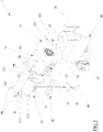
- a lift for loads according to an embodiment of the present invention has been globally indicated with 1.
- the lift 1 comprises a lifting group 10 and a generator group 20.
- the lift also comprises a support frame 30, to which the generator group 10 and the lifting group 20 are or can be fixed - as described in greater detail hereinafter.
- the lifting group 10 comprises a rotating drum 11, a lifting cable 13 associated with the rotating drum 11, and an electric motor 15.
- the rotating drum 11 has a reel-type structure suitable for receiving the lifting cable 13 while it winds. Moreover, the rotating drum 11 is axially coupled with the electric motor 15. In other words, the rotating drum 11 is coupled, preferably axially, with the shaft (not visible) of the electric motor 15 to be set in rotation by it.
- the electric motor 15 comprises a motor block 151, a feeding block 153, equipped with a connector for an electric cable, and, possibly, a reducing block 155 arranged between the motor block 151 and the rotating drum 11.
- the rotating drum 11 is operatively connected to the shaft of the electric motor 15 through the reducing block 155.
- the lifting cable 13 comprises a first end, which is fixed to the rotating drum 11, and a second free end, opposite the first end.
- An operative element 40 like a hook or a basket, is preferably fixed to the second end of the lifting cable 13.
- an end stop element 50 for example a disc-shaped element made of metal, can be fixed close to the second end of the lifting cable 13.
- the lifting group 10 comprises an end stop assembly 60 comprising a rod or lever 61 hinged to the electric motor 15 and a ring 63 fixed to a first end of the lever 61 itself.
- the lever 61 projects transversally to the electric motor 15 towards the rotating drum 11 so that, in operative position, the ring 63 is beneath the rotating drum and crossed by the lifting cable 13.
- a second end of the lever 61 is operatively coupled with a switch of the feeding block 153 of the electric motor 15.
- the generator group 20 comprises an endothermic engine 21 and an energy converter 23 operatively connected to the endothermic engine 21, so as to transform the mechanical energy of the endothermic engine 21 into electrical energy.
- the generator group 20 also comprises a fuel tank 25 operatively connected to the endothermic engine 21.
- the energy converter 23 comprises a shaft (not illustrated) connected to a corresponding shaft (not illustrated) of the endothermic engine 21, possibly through a corresponding reducer (not illustrated).
- the generator group 20 further comprises an inverter 27 operatively connected to the energy converter 23 and coupled, or able to be coupled, with the electric motor 15 of the lifting group 10.
- the inverter 25 is coupled, or can be coupled, with the feeding block 153 of the electric motor 15.
- the inverter 25 can be coupled with the feeding block 153 through an electric cable (not illustrated).
- the lift 1 can comprise a control module (not illustrated), electrical or electronic, operatively connected to the electric motor 15 and, possibly, to the endothermic engine 21.
- the control module comprises a user interface, for example a keypad.
- the inverter 27 is coupled with the control module to feed it with electrical energy; in particular, extremely ow voltage electrical energy, or ELV.
- the inverter 27 is configured to supply the control module with electrical energy at a voltage value equal to or less than 24 V.
- control module or at least the user interface, can be separated from the lift 1, for example it comprises an (electrical) connection cable of predetermined length or a radio frequency transmission system. In this way, the operator can actuate the lift a desired distance from it.
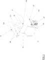
- the support frame 30 comprises a first portion 31 connected to the lifting group 10 and a second portion 33 connected to the generator group 20.
- the first portion 30 of the support frame 31 comprises a body 311 with an elongated shape extending longitudinally.
- the body 311 is a tubular element, having a square section in the non-limiting example of the figures.
- the rotating drum 11 and the electric motor 15 are mounted along an axial direction of the first portion so that the rotation axis of the rotating drum 11 and of the shaft of the electric motor 15 are parallel to the longitudinal axis of the first portion 31 of the support frame 30.
- the rotating drum 11 is fixed to the first portion 31 of the support frame 30 so as to rotate around its own rotation axis.
- the rotating drum 11 can be hinged to a pair of brackets 313 arranged at opposite sides of the rotating drum 11 and fixed to the first portion 31 of the support frame 30.
- the electric motor 15 can be fixed directly - for example, through a body thereof - or through other brackets 313 to the first portion 31 of the support frame 30.
- first portion 31 of the support frame 30 can comprise protective elements 315, like canopies - for example formed from curved plates - projecting from opposite sides of the first portion 31 so as to at least partially protect the rotating drum 11 and the electric motor 15 from contact with foreign bodies and/or atmospheric agents (in particular rain).
- protective elements 315 like canopies - for example formed from curved plates - projecting from opposite sides of the first portion 31 so as to at least partially protect the rotating drum 11 and the electric motor 15 from contact with foreign bodies and/or atmospheric agents (in particular rain).
- the second portion 33 of the support frame 30 comprises a bearing element 331 and a connection element 333.
- the bearing element 331 of the second portion 33 is configured to support the generator group 20.
- the bearing element 331 comprises a support base 335 suitable for receiving and/or allowing the attachment of the endothermic engine 21 - with which the tank 25 is coupled -, the energy converter 23 and the inverter 27.
- the bearing element 331 comprises a constraining portion 337 transversal to the resting base 335 with a first end coupled with the resting base and a second end, opposite the first, coupled with the connection element 333.
- the bearing element 331 also comprises a resting portion 339 - connected to the resting base 335 and projecting from it in the opposite direction with respect to the constraining portion 337 - suitable for keeping the second portion 33 in a stable position on a resting surface, at the same time keeping the generator group 20 spaced from the surface itself.
- the bearing element 331 of the second portion 33 comprises tubes and/or rods coupled together.
- the bearing element 331 can be equipped with a plate 70 suitable for defining a barrier - for example to protect and/or prevent a contact by foreign bodies at at least one part of the endothermic engine 21 and/or of the energy converter 23 and/or limiting the heat dispersion from the endothermic engine 21 to the energy converter 23 (and vice-versa).
- connection element 333 has an elongated shape extending longitudinally.
- the connection element 333 is coupled with the constraining portion 337 with its longitudinal (main) axis arranged transversally with respect to a main axis of extension of the constraining portion 337.
- connection element 333 is a tubular element with section - square in the non-limiting example of the figures - smaller than the section of the body 311 of the first portion 31 of the frame 30.
- the section of the connection element 333 is such as to allow the insertion, preferably snug, thereof in the body 311 of the first portion 31 of the support frame 30.
- the body 311 of the first portion 31 and the connection element 333 of the second portion 33 operate as a first coupling element and a second coupling element, respectively, suitable for coupling together.
- the body 311 and the connection element 333 each comprise fixing elements suitable for ensuring mutual fixing.
- the body 311 and the connection element 333 comprise through holes, four in the example considered.
- the through holes are formed so as to define (two) pairs of through holes coaxial and transversal to the longitudinal axes of the body 311 and of the connection element 333.
- each pair of holes of the body 311 is coaxial to a corresponding pair of holes of the connection element 333, when the connection element 333 is inserted in the body 311.
- a joining element like a bolt 80.
- a screw of the bolt 80 is slotted in the aligned pairs of through holes and the nut is fixed to a (threaded) free end of the screw.
- the support frame 30 comprises one or more moving elements 90, two in the example considered, to allow a sliding coupling with the suspension structure.
- the moving elements 90 comprise one or more among: a roller; a sliding block; a belt; a chain, and a slide.
- every moving element 90 comprises a pair of rollers, preferably idle, projecting from opposite sides to the support frame 30 with respect to the longitudinal axis thereof.
- the moving elements 90 are fixed to the first portion 31 thereof, even more preferably on one side of the first portion 31 opposite to the side to which the lifting group 10 is fixed with respect to the longitudinal axis of the first portion 31.
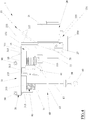
- the lift 1 can form part of a lifting system 100 comprising a suspension structure 110 with which the support frame 30 of the lift can be associated, preferably in a sliding manner. Once the frame 30 is associated with the suspension structure 110, the latter keeps both the lifting group 10 and the generator group 20 spaced from the resting surface at a predetermined height.
- the suspension structure 110 comprises one or more, for example two, spacing elements 120, a guide element 130 and, preferably, a base element 140.
- the spacing elements 120 have a first end for resting on the resting surface and a second end, opposite to the first end, coupled with the guide element 130.
- the spacing elements 120 are associated transversal to the base portion 140 and, consequently, transversal to the resting surface.
- the spacing elements 120 are shaped like an ' ⁇ ' (i.e. an inverted U) with a pair of resting ends facing towards the resting surface and a distal curved portion with which the guide element 130 is coupled.
- an additional element 125 for the distribution of the weight can be associated with each spacing element 120.
- the additional element 120 is also shaped like a ' ⁇ ' but with reduced extension with respect to the spacing element 120 and is hinged to it at a predetermined height, for example greater than half the extension of the spacing element 120 from the resting ends thereof.
- the guide element 130 comprises a pair of guides 135 arranged symmetrically with respect to a longitudinal axis of the suspension structure.
- the guides 135 are sized so as to slidably receive the moving elements 90 of the support frame 30.
- the guides 135 have a C-shaped profile suitable for receiving the rollers of the moving elements 90 and allowing the rolling thereof.
- the guides are fixed to the spacing elements 120 at a concavity of the respective curved portions.
- the base element 140 if provided, is suitable for coming into contact with the resting surface.
- the base portion 140 comprises (four) rods constrained together so as to define a parallelogram arrangement (in plan), preferably rectangular.
- the resting ends of the spacing element 120 are coupled with the base element 140 at the vertices thereof, so as to obtain a support structure 110 that is particularly strong and capable of supporting a great weight for example of the order of one thousand kilograms (1000 Kg).
- the lifting group 10 coupled with the first portion 31 of the support frame 30, the generator group 20 coupled with the second portion 33 of the support frame 30, and the suspension structure 110 can be transported as separate elements and mounted at the location of use.
- the second portion 33 is inserted in the first portion 31 that are thus fixed together by means of the bolts 80 as described earlier.
- the generator group 20 is electrically connected to the lifting group 10.
- the inverter 27 of the generator group 20 is connected to the feeding block 153 of the electric motor 15, for example through an electric cable (not illustrated).
- the support frame 30 can be fixed to a fixed and/or hinged support (not illustrated) - known in the field and not described here for the sake of brevity - or can be slidably associated with the suspension structure 110 to define the lifting system 100 as described above.
- the lift 1 - or the lifting system 100 - is thus completely mounted and ready for use to lift and lower loads (not illustrated) fixed to the operative element 40, in a way that can be controlled by an operator through the user interface of the control module.
- the control module possibly remotely.
- the counterweight 50 or the operative element 40 would make contact with the end stop assembly 60 making the latter rotate about its pin. This rotation leads to the actuation of the switch of the feeding block of the feeding block 153 and thus to switching off the electric motor 15, preventing the lifting group 10 from being hit by the operative element 40 and/or by a lifted load connected to it.
- the generator group 20 can be removed or not associated with the lifting group 10, i.e. the first portion 31 and the second portion 33 of the support frame 30 are not coupled or are separated, and the feeding block can be connected to the electrical mains through an electric cable.
- the feeding block of the electric motor can be integrated in the motor block thereof.
- the inverter can be integrated in the energy converter.
- the lift can comprise, for example in the generator group, one or more batteries, preferably rechargeable by the energy converter and operatively connected to the inverter.
- the moving element and/or the guide element can comprise a brake or another stop element to ensure the parking of the lift in a desired operative position.
- the moving element can be motorised, for example it can comprise motorised rollers or wheels, operatively connected to the electric motor to receive actuation energy from it.
- the materials used can be whatever according to the requirements without for this reason departing from the scope of protection of the following claims.
- the materials used are suitable for interaction with heavy loads, for example of the order of one thousand kilograms; for example, at least the support frame, the rotating drum, the lifting cable, the operative element and the suspension structure are formed from a strong material like steel or another metal alloy.
Landscapes
- Engineering & Computer Science (AREA)
- Mechanical Engineering (AREA)
- Automation & Control Theory (AREA)
- Lift-Guide Devices, And Elevator Ropes And Cables (AREA)
- Types And Forms Of Lifts (AREA)
- Load-Engaging Elements For Cranes (AREA)
Applications Claiming Priority (1)
| Application Number | Priority Date | Filing Date | Title |
|---|---|---|---|
| IT102018000005000A IT201800005000A1 (it) | 2018-05-02 | 2018-05-02 | Elevatore e sistema elevatore comprendente lo stesso |
Publications (1)
| Publication Number | Publication Date |
|---|---|
| EP3564181A1 true EP3564181A1 (fr) | 2019-11-06 |
Family
ID=62816994
Family Applications (1)
| Application Number | Title | Priority Date | Filing Date |
|---|---|---|---|
| EP19171514.3A Withdrawn EP3564181A1 (fr) | 2018-05-02 | 2019-04-29 | Élévateur et système de levage le comprenant |
Country Status (3)
| Country | Link |
|---|---|
| EP (1) | EP3564181A1 (fr) |
| IT (1) | IT201800005000A1 (fr) |
| MA (1) | MA49707A (fr) |
Cited By (2)
| Publication number | Priority date | Publication date | Assignee | Title |
|---|---|---|---|---|
| IT202100009212A1 (it) * | 2021-04-13 | 2022-10-13 | Cristian SORCE | Azzeratore di peso |
| WO2024077362A1 (fr) * | 2022-10-11 | 2024-04-18 | Costa Luiz Henrique | Ensemble amplificateur pour treuils électriques ou similaires |
Citations (4)
| Publication number | Priority date | Publication date | Assignee | Title |
|---|---|---|---|---|
| WO2004056689A1 (fr) * | 2002-12-19 | 2004-07-08 | Hhh Manufacturing Co. | Palan electrique |
| WO2006113844A1 (fr) * | 2005-04-20 | 2006-10-26 | Atlas Devices, Llc. | Ascendeur de corde electrique et dispositif de tirage de corde portable |
| EP2990573A1 (fr) * | 2014-08-28 | 2016-03-02 | Champion Door Oy | Mécanisme de treuillage |
| DE102015116506A1 (de) * | 2015-09-29 | 2017-03-30 | Olko-Maschinentechnik Gmbh | Mobile Schachtwinde |
-
2018
- 2018-05-02 IT IT102018000005000A patent/IT201800005000A1/it unknown
-
2019
- 2019-04-29 EP EP19171514.3A patent/EP3564181A1/fr not_active Withdrawn
- 2019-04-29 MA MA049707A patent/MA49707A/fr unknown
Patent Citations (5)
| Publication number | Priority date | Publication date | Assignee | Title |
|---|---|---|---|---|
| WO2004056689A1 (fr) * | 2002-12-19 | 2004-07-08 | Hhh Manufacturing Co. | Palan electrique |
| WO2006113844A1 (fr) * | 2005-04-20 | 2006-10-26 | Atlas Devices, Llc. | Ascendeur de corde electrique et dispositif de tirage de corde portable |
| EP2990573A1 (fr) * | 2014-08-28 | 2016-03-02 | Champion Door Oy | Mécanisme de treuillage |
| DE102015116506A1 (de) * | 2015-09-29 | 2017-03-30 | Olko-Maschinentechnik Gmbh | Mobile Schachtwinde |
| CA2999191A1 (fr) * | 2015-09-29 | 2017-04-06 | Olko-Maschinentechnik Gmbh | Treuil de puits mobile |
Non-Patent Citations (1)
| Title |
|---|
| GROWA F.E. PTE LTD, 25 October 2016 (2016-10-25), XP002787817, Retrieved from the Internet <URL:https://web.archive.org/web/20161025041747/https://www.growa.net/Electric%20and%20Diesel%20Hoists> [retrieved on 20190110] * |
Cited By (2)
| Publication number | Priority date | Publication date | Assignee | Title |
|---|---|---|---|---|
| IT202100009212A1 (it) * | 2021-04-13 | 2022-10-13 | Cristian SORCE | Azzeratore di peso |
| WO2024077362A1 (fr) * | 2022-10-11 | 2024-04-18 | Costa Luiz Henrique | Ensemble amplificateur pour treuils électriques ou similaires |
Also Published As
| Publication number | Publication date |
|---|---|
| MA49707A (fr) | 2020-06-03 |
| IT201800005000A1 (it) | 2019-11-02 |
Similar Documents
| Publication | Publication Date | Title |
|---|---|---|
| KR102246338B1 (ko) | 변압기로의 가공배전선 분기가 용이한 가공배전설비 | |
| US10100541B1 (en) | Precast lightweight wall panel installation machine | |
| CA2774002C (fr) | Panier pouvant etre installe par helicoptere permettant le deplacement le long des lignes electriques | |
| US20030091417A1 (en) | Portable power lifter | |
| CN201092518Y (zh) | 智能轻型吊装机 | |
| KR101964633B1 (ko) | 레일을 이용한 지중 케이블의 기계화 포설 장치 | |
| EP1879536B1 (fr) | Système de manipulation conçu pour soulever ou déplacer une personne, système de pesée, et procède pour soulever et déplacer une personne | |
| US6048012A (en) | Understructure lifting beam | |
| CN107658785B (zh) | 丝杠驱动的柱式绝缘子快速更换装置 | |
| CN213205004U (zh) | 建筑用导轨式行走接料平台 | |
| CN205442529U (zh) | 手动搬运车 | |
| US7032289B2 (en) | Stator bar handler | |
| CN114291120B (zh) | 电力设备运输装置 | |
| CN109687329A (zh) | 一种开关柜后柜门定位装置 | |
| US7017963B1 (en) | Counter weighted lifting beam | |
| IT201800005000A1 (it) | Elevatore e sistema elevatore comprendente lo stesso | |
| US20010006596A1 (en) | Mobile lift and storage apparatus | |
| KR101764168B1 (ko) | 정밀설비 운반트롤리용 커넥터 | |
| CN116873778A (zh) | 工业厂房钢结构吊装装置及其施工方法 | |
| CN112225072A (zh) | 一种基于装配建筑施工用精确定位的起重机吊运装置 | |
| CN211998602U (zh) | 一种变电站内电气设备用节能装置 | |
| EP1801318A1 (fr) | Véhicule pour le transport de matériaux sur l'extérieur de bâtiments | |
| KR200234050Y1 (ko) | 차량용 크레인장치 | |
| CN115159336B (zh) | 一种用于平稳吊装变电站构支架的起重机 | |
| KR101829577B1 (ko) | 부싱 설치 장치 |
Legal Events
| Date | Code | Title | Description |
|---|---|---|---|
| PUAI | Public reference made under article 153(3) epc to a published international application that has entered the european phase |
Free format text: ORIGINAL CODE: 0009012 |
|
| STAA | Information on the status of an ep patent application or granted ep patent |
Free format text: STATUS: THE APPLICATION HAS BEEN PUBLISHED |
|
| AK | Designated contracting states |
Kind code of ref document: A1 Designated state(s): AL AT BE BG CH CY CZ DE DK EE ES FI FR GB GR HR HU IE IS IT LI LT LU LV MC MK MT NL NO PL PT RO RS SE SI SK SM TR |
|
| AX | Request for extension of the european patent |
Extension state: BA ME |
|
| STAA | Information on the status of an ep patent application or granted ep patent |
Free format text: STATUS: REQUEST FOR EXAMINATION WAS MADE |
|
| 17P | Request for examination filed |
Effective date: 20200427 |
|
| RAV | Requested validation state of the european patent: fee paid |
Extension state: KH Effective date: 20200427 Extension state: MA Effective date: 20200427 Extension state: MD Effective date: 20200427 Extension state: TN Effective date: 20200427 |
|
| RAX | Requested extension states of the european patent have changed |
Extension state: BA Payment date: 20200427 Extension state: ME Payment date: 20200427 |
|
| RBV | Designated contracting states (corrected) |
Designated state(s): AL AT BE BG CH CY CZ DE DK EE ES FI FR GB GR HR HU IE IS IT LI LT LU LV MC MK MT NL NO PL PT RO RS SE SI SK SM TR |
|
| RAP1 | Party data changed (applicant data changed or rights of an application transferred) |
Owner name: E.C.E. - S.R.L. |
|
| STAA | Information on the status of an ep patent application or granted ep patent |
Free format text: STATUS: EXAMINATION IS IN PROGRESS |
|
| 17Q | First examination report despatched |
Effective date: 20211213 |
|
| STAA | Information on the status of an ep patent application or granted ep patent |
Free format text: STATUS: THE APPLICATION IS DEEMED TO BE WITHDRAWN |
|
| 18D | Application deemed to be withdrawn |
Effective date: 20220624 |