EP3564441A1 - Stützwerk zum schutz vor lawinen, steinschlägen und erdrutschen - Google Patents
Stützwerk zum schutz vor lawinen, steinschlägen und erdrutschen Download PDFInfo
- Publication number
- EP3564441A1 EP3564441A1 EP19170828.8A EP19170828A EP3564441A1 EP 3564441 A1 EP3564441 A1 EP 3564441A1 EP 19170828 A EP19170828 A EP 19170828A EP 3564441 A1 EP3564441 A1 EP 3564441A1
- Authority
- EP
- European Patent Office
- Prior art keywords
- support
- supporting structure
- beams
- damping plates
- damping
- Prior art date
- Legal status (The legal status is an assumption and is not a legal conclusion. Google has not performed a legal analysis and makes no representation as to the accuracy of the status listed.)
- Granted
Links
Images

Classifications
-
- E—FIXED CONSTRUCTIONS
- E01—CONSTRUCTION OF ROADS, RAILWAYS, OR BRIDGES
- E01F—ADDITIONAL WORK, SUCH AS EQUIPPING ROADS OR THE CONSTRUCTION OF PLATFORMS, HELICOPTER LANDING STAGES, SIGNS, SNOW FENCES, OR THE LIKE
- E01F7/00—Devices affording protection against snow, sand drifts, side-wind effects, snowslides, avalanches or falling rocks; Anti-dazzle arrangements ; Sight-screens for roads, e.g. to mask accident site
- E01F7/04—Devices affording protection against snowslides, avalanches or falling rocks, e.g. avalanche preventing structures, galleries
-
- E—FIXED CONSTRUCTIONS
- E01—CONSTRUCTION OF ROADS, RAILWAYS, OR BRIDGES
- E01F—ADDITIONAL WORK, SUCH AS EQUIPPING ROADS OR THE CONSTRUCTION OF PLATFORMS, HELICOPTER LANDING STAGES, SIGNS, SNOW FENCES, OR THE LIKE
- E01F7/00—Devices affording protection against snow, sand drifts, side-wind effects, snowslides, avalanches or falling rocks; Anti-dazzle arrangements ; Sight-screens for roads, e.g. to mask accident site
- E01F7/04—Devices affording protection against snowslides, avalanches or falling rocks, e.g. avalanche preventing structures, galleries
- E01F7/045—Devices specially adapted for protecting against falling rocks, e.g. galleries, nets, rock traps
Definitions
- the invention relates to the field of construction engineering in the field of avalanche control.
- the present invention relates to a supporting structure and the use of such a supporting structure for avalanche and debris protection.
- Avalanche barriers in the Anbruch have the task to prevent the dawn of snow avalanches.
- several rows of support structures are installed in the avalanche area.
- two types of constructions are known in the prior art, namely rigid and resilient support structures.
- steel snow bridges are called a rust of steel, which absorbs from avalanches, landslides and rockfalls outgoing loads with only a small deformation of a few centimeters and thus hold the snow in the avalanche slope.
- steel snow bridges consist of a grid of horizontal beams and down-facing posts. As the creeping and sliding snow masses exert a high static pressure on the snow bridges, the supports are fixed to the ground by solid concrete foundations. Steel snow bridges prevent the ripping of an avalanche in the break-up area by supporting the snowpack.
- Resilient support structures such as snow grids, can follow the movement of the snow due to their construction over several decimetres. Thanks to their high flexibility, snow nets are relatively insensitive to damage caused by rockfalls.
- avalanche barriers in avalanche prone areas consist of a combination of snow or rockfall protection nets and steel snow bridges.
- snow or rockfall protection nets are, from an economic point of view, much more disadvantageous in terms of service life, investment and maintenance costs than steel snow bridges, which can have a lifetime of up to 100 years.
- steel snow bridges are more often destroyed or damaged by rockfalls than snow protection nets. This is often due to the design of classic steel snow bridges.
- the horizontal beams connecting two beams are often pierced by stones or boulders or deformed to greatly reduce the utility of the steel snow bridge.
- rockfall energies are significantly attenuated and the dynamic peak pressure of a rockfall is reduced.
- the invention in a first aspect, relates to a support structure for avalanche, rockfall and landslide protection comprising a grate structure, the grate structure comprising beams.
- a support structure typically includes crossing points of beams and damping plates.
- the damping plates are connected to the beams.
- the support mechanism further comprises a support element, which is operatively connected to the beams.
- the beams are mounted on the support member, whereby the support structure has a layer construction in which the support member, the lower layer, the beam, the middle layer and the damping plates form the upper layer.
- the support structure according to the invention comprises at least one support with a spring element, which is operatively connected to the support element.
- the spring element has the effect that the impact energy of an impact can be at least partially absorbed, which makes the support structure more resistant and more durable.
- a grate or a grate structure according to the invention is formed by a plurality of intersecting elements, in the present case beams and damping plates, and therefore has a layer structure in contrast to a grid.
- damping plates in the operational state are turned-down means in the sense of the invention that these are mounted on the beams and thus exposed directly to any possible chipping.
- the damping plates in the layer structure of the rust structure form the upper layer.
- the damping plates are designed to absorb part of the impact energy of a rockfall or an avalanche due to their damping property, so that the supporting structure is not damaged by a rockfall or an avalanche.
- the damping plates transmit the impact energy uniformly over the entire grate structure, in particular over the beams.
- the compound of damping plates and beams is non-positively, positively or materially and preferably includes screw, rivets, welding, adhesive or similar compounds.
- Such compounds are shear-resistant and therefore increase the flexural rigidity and the load-bearing capacity of the rust structure considerably.
- the at least one support is arranged at an angle to the carrier element.
- the angle can be adapted to the respective topographical conditions and is typically between 50 ° and 80 °, preferably between 60 ° and 70 °.
- the support structures in the operative state with one or more foundations, preferably made of concrete, connected.
- the support structures can be screwed, welded or glued to a fastening connected to the foundation.
- the at least one support of the supporting structure is downhill and the damping plates are facing the slope.
- the at least one support is operatively connected by a hinge pivotally connected to the carrier element.
- the joint may for example be a hinge joint.
- the joint may also be a ball joint, pivot joint or saddle joint. Such a joint protects the connection region between the support and the support element, since this shearing forces occurring when impact of an avalanche or a rockfall can be efficiently transmitted to the spring element.
- the support element of the support structure comprises one or more carriers.
- the carriers can be arranged transversely, in particular perpendicular, to the bars.
- the carrier element comprises two or more carriers, which are arranged substantially parallel to each other.
- the carriers form the lateral boundary of the carrier element and are connected to the beams at the ends thereof or at least in the region of their ends with the beams.
- the carrier element may form an open, in particular a U-shaped, or closed frame or comprise a plurality, preferably two, parallel arranged carriers.
- the carrier element may consist of a transverse and two longitudinal members, or of two transverse and two longitudinal members, which are each connected to each other.
- the damping plates may be non-positively, positively or materially connected to the bars at substantially each crossing point.
- limit tensile forces and ultimate shear forces of 80 to 120 kN, preferably 95 to 105 kN, may be transmittable at each joint between the beam and the damper plates. As a result, a particularly massive rust structure is achieved.
- connection between beams and damping plates preferably comprises screw connections of strength class 4.6, 4.8 or 5.8.
- the baffles are designed to plastically and / or elastically deform during a rockfall, thereby significantly reducing the potential damage to the steel snow bridge during a rock fall.
- the damping plates have, in particularly preferred embodiments, a U-shaped, rectangular, triangular, trapezoidal or parabolic cross-section. As a result, a good damping effect can be achieved, and the dynamic peak pressure due to a rockfall can be reduced. Furthermore, the damping plates on the Upper side, ie on the side facing away from the beams, have a convex or concave curvature. In a rockfall this can be deformed and thus the impact energy of any rockfall are at least partially absorbed.
- the damping plates in cross section have a height of 30 to 400 mm, preferably 50 to 200 mm and a width of 30 to 300 mm, preferably 80 to 150 mm.
- the grid or the grate structure of a steel snow bridge or a supporting structure according to the invention has a length of 0.5 to 10 m and a height of 0.5 to 5 m.
- the at least one support has a first and a second support element, which are designed to be displaceable one inside the other and wherein the spring element is arranged wholly or partly inside at least one of the two support elements.
- at least one of the two support elements may be configured as a hollow body, in which the other support member is slidably insertable. It can also be configured as a hollow body, both support elements, wherein one of the support elements has a smaller diameter or smaller edge lengths than the other support member.
- one of the support elements typically has an intermediate plate, which can be welded in, for example, to which the spring element is fastened or on which the spring element rests or rests. Such embodiments are particularly advantageous, since the spring element is protected by its arrangement of external influences, such as weathering and ice deposits.
- the spring element has a spring stiffness of 700 to 2500 N / mm, preferably 1200 to 1800 N / mm.
- the spring element is preferably a spiral spring. However, it is also possible to use an elastic material such as rubber.
- the grate structure, the support element and / or the at least one support made of steel, wood or reinforced concrete.
- the beams are made of steel with a moment of inertia of the main load direction of 300 to 900 cm 4 , preferably 500 to 700 cm 4 and / or the damping steel sheets with a moment of inertia to the main load direction of 500 to 1500 cm 4 , preferably 800 to 1200 cm 4 .
- the beams and the damper plates are not identical.
- the beams can be made of a different material than the damping plates or have a different cross-section.
- the beams may consist of steel of grade S355 and / or the damping plates of steel grade S235.
- the beams and / or the beams are H-shaped, circular, rectangular, triangular or elliptical in cross-section.
- the damping plates are elastic and / or plastically deformable.
- the beams are arranged substantially parallel to each other.
- the bars may also be arranged substantially transversely, in particular perpendicular, to the carrier element and / or arranged transversely, in particular perpendicular to the damping plates. In the operative state, the beams thus run essentially horizontally to the slope and the damping plates are substantially vertical to the slope.
- the beams can run parallel to the horizontal part of the frame and transversely, in particular perpendicular to the vertical part of the frame.
- a further aspect of the invention is the use of a support structure according to the invention described above for the protection against avalanches, rockfalls and landslides, preferably in the avulsion area of avalanches.
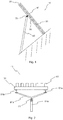
- FIG. 1 illustrated schematic view shows an embodiment of an inventive support structure 10 in the operative state.
- the avalanche, landslide and landslide protection support 10 includes a grate structure 20 having beams 30 and damper plates 40 (FIGS. FIG. 1 shows only one of the damping plates).
- the damping plates 40 are connected to the bars 30 and arranged in the operative state shown in the manner of a slope.
- the grate structure 20 further comprises a carrier element 50, which in the present embodiment is arranged transversely, for example vertically, to the slope and connected to the beams 30.
- the layer structure of the grate structure 20 is shown by way of example.
- the carrier element 50 forms the lower layer, the bars 30, the middle layer and the damping plates 40, the upper layer.
- the support structure according to the invention furthermore comprises a support 60 with a spring element 70, the support being in operative connection with the support element 50.
- the support 60 of the embodiment shown is formed in one piece and the spring element 70 is at least partially disposed outside the support 60.
- the spring element 70 may be connected directly to the carrier element 50.
- a joint can be arranged between the spring element 70, in which case the support 60 is pivotally operatively connected to the carrier element 50.
- the support structure 10 comprises two or even more supports 60.
- the carrier element 51 comprises two carriers 51a and 51b, which have an H-shaped cross section, as is customary, for example, for steel profile carriers familiar to the person skilled in the art.
- the brackets 51a and 51b in the illustrated embodiment are each connected substantially at the ends of the beams 31 therewith.
- the damping plates 41, which are connected to the beams 31, in the present embodiment are of cuboid design and typically have a cavity.
- the support comprises in the embodiment shown, a first support member 61a and a second support member 61b, which are designed to be displaceable.
- Both support elements 61a and 61b are configured at least in the insertion region as a hollow body.
- the spring element 71 is arranged completely inside the support elements 61a and 61b and is therefore protected against external influences.
- a support structure 11 according to the invention may also comprise two or more supports each having two support elements and a spring element which are in each case operatively connected to one of the two supports 51a and 51b.
- FIG. 3 is a schematic plan view of a rust structure 22 of a further embodiment of the invention shown.
- the support element 52 forms an open, in this case downwardly open, U-shaped frame with two vertical supports 52a and 52b and a horizontal support 52c, which are interconnected.
- the carriers 52a and 52b are arranged substantially parallel to one another.
- On the support member bars 32 are arranged, which are arranged transversely to the vertical beams 52a and 52b in the present embodiment.
- the illustrated grate structure 22 includes a plurality of damper plates 42 which are secured to the beams 32 by screw connections 80 at substantially each intersection point.
- One Supporting structure 12 according to the invention for protection against avalanches, rockfalls and landslides can, for example, in addition to the in FIG. 3 shown rust structure 22 one, two or as needed comprise a plurality of supports with a spring element (not shown), wherein the supports are typically operatively connected to the support member and optionally operatively connected via a hinge with the support member
- FIG. 4 an enlarged section of a schematic side view of an inventive support structure 13 is shown according to a further embodiment.
- the support mechanism 13 comprises, in addition to the carrier element 53, the beam 33 and the damping plates 43, at least one support which has a first support element 63a and a second support element 63b, which are designed to be displaceable one inside the other.
- the first support element 63a is in this case designed such that it is displaceable in the second support member 63b.
- the first support element 63a has a smaller diameter or a smaller edge length than the second support element 63b.
- the first support element comprises an intermediate plate 90, which is typically welded in and to which the spring element 73 is fastened or on which it rests.
- a hinge 100 is shown, through which the at least one support is pivotally operatively connected to the carrier element 53.
- the hinge 100 is in operative connection with the second support member 63b.
- the hinge 100 is preferably a hinge joint. However, other types of joints such as ball joints can be used.
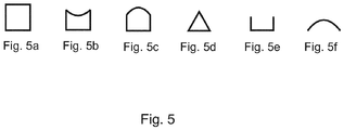
- the damping plates may be formed, for example cuboid, so that they have a square or rectangular cross-section ( Fig. 5a ) exhibit.
- a particularly effective damping effect can be achieved if the damping plates have a cavity in the interior.
- the damping plates on the upper side ie at the side facing away from the beams and the side facing the slope, a concave ( Fig. 5b ) or convex ( Fig. 5c ) Have vaulting, which in a rockfall can be deformed and so the impact energy of an impact can be at least partially absorbed.
- the damping plates can also have a substantially triangular cross section ( Fig. 5d ), wherein the corners may be rounded in some embodiments.
- the damping plates may also have a U-shaped ( Fig. 5e ) Have cross-section or at least partially convexly curved plates ( Fig. 5f ) consist.
Landscapes
- Engineering & Computer Science (AREA)
- Architecture (AREA)
- Civil Engineering (AREA)
- Structural Engineering (AREA)
- Devices Affording Protection Of Roads Or Walls For Sound Insulation (AREA)
Abstract
mindestens einer Stütze (60) mit einem Federelement (70), wobei die Stütze (60) mit dem Trägerelement (50) wirkverbunden ist.
Description
- Die Erfindung bezieht sich auf das Gebiet der Bautechnik im Bereich der Lawinenverbauung. Insbesondere bezieht sich die vorliegende Erfindung auf ein Stützwerk sowie die Verwendung eines solchen Stützwerks zum Lawinen- und Geröllschutz.
- Lawinenverbauungen im Anbruchgebiet haben die Aufgabe den Anbruch von Schneelawinen zu verhindern. Dazu werden mehrere Reihen Stützwerke im Anbruchgebiet der Lawine verbaut. Grundsätzlich sind im Stand der Technik zwei Arten von Verbauungen bekannt, nämlich starre und nachgiebige Stützwerke.
- Als starre Stützwerke werden Stahlschneebrücken mit einem Rost aus Stahl bezeichnet, welche von Lawinen, Erdrutschen und Steinschlägen ausgehende Belastungen mit nur geringer Deformation von wenigen Zentimetern aufnehmen und den Schnee somit im Lawinenhang festhalten. Im Allgemeinen bestehen Stahlschneebrücken aus einen Rost aus horizontalen Balken und talwärts-weisenden Stützen. Da die kriechenden und gleitenden Schneemassen dabei einen hohen statischen Druck auf die Schneebrücken ausüben, werden die Stützen durch stabile Betonfundamente am Boden befestigt. Stahlschneebrücken verhindern bereits im Anbruchgebiet das Losreissen einer Lawine indem die Schneedecke abgestützt wird.
- Nachgiebige Stützwerke, wie beispielsweise Schneenetze können der Bewegung des Schnees aufgrund ihres Aufbaus über mehrere Dezimeter folgen. Schneenetze sind durch ihre hohe Flexibilität relativ unempfindlich gegen Beschädigung durch Steinschläge.
- Des Öfteren bestehen Lawinenverbauungen in steinschlaggefährdeten Anbruchgebieten aus einer Kombination aus Schnee- oder Steinschlagschutznetzen und Stahlschneebrücken. Schnee- oder Steinschlagschutznetze sind jedoch aus wirtschaftlicher Sicht bezüglich Nutzungsdauer, Investitions-und Unterhaltskosten wesentlich nachteiliger als Stahlschneebrücken, welche eine Lebensdauer von bis zu 100 Jahren aufweisen können. Allerdings werden Stahlschneebrücken durch Steinschläge öfter zerstört oder beschädigt als Schneeschutznetze. Dies ist häufig durch die Bauart klassischer Stahlschneebrücken bedingt. Die horizontalen Balken, welche zwei Träger verbinden, werden häufig von Steinen oder Felsbrocken durchstossen oder derart verformt, dass der Nutzen der Stahlschneebrücke stark reduziert wird.
- Es ist daher Aufgabe der Erfindung den Stand der Technik im Bereich der Lawinen- und Steinschlagverbauungen weiterzuentwickeln und vorzugsweise die Nachteile des Standes der Technik zu überwinden. In vorteilhaften Ausführungsformen können durch die vorliegende Erfindung stabilere Stützwerke bereitgestellt werden, welche eine höhere Lebensdauer und geringere Reparaturkosten aufweisen als herkömmliche Stahlschneebrücken.
- In weiteren vorteilhaften Ausführungsformen werden Steinschlagenergien signifikant abgeschwächt und der dynamische Spitzendruck eines Steinschlags reduziert.
- Diese Aufgaben werden in allgemeiner Weise durch den Gegenstand der unabhängigen Patentansprüche gelöst.
- Weitere vorteilhafte Ausführungsformen ergeben sich jeweils aus den abhängigen Ansprüchen, sowie der Offenbarung insgesamt.
- In einem ersten Aspekt betrifft die Erfindung ein Stützwerk zum Schutz vor Lawinen, Steinschlägen und Erdrutschen umfassend eine Roststruktur, wobei die Roststruktur Balken umfasst. Auf den Balken sind Dämpfungsbleche angebracht, welche im operativen Zustand hangzugewandt sind. Somit bilden die Balken und Dämpfungsbleche einen Schichtaufbau, wobei die Dämpfungsbleche die oberste Schicht bilden und einem etwaigen Steinschlag direkt exponiert sind. Ein solches Stützwerk umfasst typischerweise Kreuzungspunkte von Balken und Dämpfungsblechen. Die Dämpfungsbleche sind mit den Balken verbunden. Das Stützwerk umfasst weiter ein Trägerelement, welches mit den Balken wirkverbunden ist. Typischerweise sind die Balken auf dem Trägerelement angebracht, wodurch das Stützwerk einen Schichtaufbau aufweist bei welchem das Trägerelement die untere Schicht, die Balken die mittlere Schicht und die Dämpfungsbleche die obere Schicht bilden. Zusätzlich umfasst das erfindungsgemässe Stützwerk mindestens eine Stütze mit einem Federelement, die mit dem Trägerelement wirkverbunden ist. Das Federelement bewirkt unter anderem, dass die Aufschlagenergie eines Einschlags zumindest teilweise absorbiert werden kann, wodurch das Stützwerk widerstandsfähiger und langlebiger wird.
- Ein Rost oder eine Roststruktur im Sinne der Erfindung wird durch mehrere, sich kreuzende Elemente, im vorliegenden Fall Balken und Dämpfungsbleche, gebildet und weist daher im Gegensatz zu einem Gitter einen Schichtaufbau auf.
- Dass die Dämpfungsbleche im operativen Zustand hangzugewandt sind bedeutet im Sinne der Erfindung, dass diese auf den Balken angebracht sind und somit direkt einem etwaigen Steinschlag exponiert sind. Somit bilden die Dämpfungsbleche im Schichtaufbau der Roststruktur die obere Schicht. Ein solcher Aufbau hat sich als besonders vorteilhaft erwiesen, da die Dämpfungsbleche aufgrund ihrer dämpfenden Eigenschaft dazu ausgebildet sind, einen Teil der Aufschlagsenergie eines Steinschlags oder einer Lawine zu absorbieren, sodass das Stützwerk durch einen Steinschlag oder eine Lawine nicht beschädigt wird. Des Weiteren übertragen die Dämpfungsbleche die Aufschlagsenergie gleichmässig über die gesamte Roststruktur, insbesondere über die Balken.
- Vorzugsweise ist die Verbindung von Dämpfungsblechen und Balken kraftschlüssig, formschlüssig oder stoffschlüssig und umfasst bevorzugt Schrauben-, Nieten-, Schweiss-, Klebe- oder ähnliche Verbindungen. Solche Verbindungen sind schubfest und erhöhen daher die Biegesteifigkeit und die Tragfähigkeit der Roststruktur erheblich.
- In vorteilhaften Ausführungsformen ist die mindestens eine Stütze gewinkelt zu dem Trägerelement angeordnet. Der Winkel kann dabei auf die jeweiligen topografischen Bedingungen angepasst werden und liegt typischerweise zwischen 50° und 80°, vorzugsweise zwischen 60° und 70°.
- Typischerweise sind die Stützwerke im operativen Zustand mit einem oder mehreren Fundamenten, vorzugsweise aus Beton, verbunden. Beispielsweise können die Stützwerke mit einer mit dem Fundament verbundenen Befestigung verschraubt, verschweisst oder verklebt werden. Im operativen Zustand weist die mindestens eine Stütze des Stützwerks talwärts und die Dämpfungsbleche sind dem Hang zugewandt.
- In einer weiteren vorteilhaften Ausführungsform ist die mindestens eine Stütze durch ein Gelenk schwenkbar mit dem Trägerelement wirkverbunden. Das Gelenk kann beispielsweise ein Scharniergelenk sein. In weiteren Ausführungsformen kann es sich bei dem Gelenk auch um ein Kugelgelenk, Zapfengelenk oder Sattelgelenk handeln. Eine solches Gelenk schützt den Verbindungsbereich zwischen Stütze und Trägerelement, da hierdurch beim Aufschlag einer Lawine oder eines Steinschlags auftretende Scherkräfte effizient auf das Federelement übertragen werden können.
- In bevorzugten Ausführungsformen umfasst das Trägerelement des Stützwerks einen oder mehrere Träger. Die Träger können dabei quer, insbesondere senkrecht, zu den Balken angeordnet sein. Typischerweise umfasst das Trägerelement zwei oder mehrere Träger, welche im Wesentlichen parallel zueinander angeordnet sind. Vorzugsweise bilden die Träger die seitliche Begrenzung des Trägerelements und sind mit den Balken an deren Enden oder zumindest im Bereich deren Enden mit den Balken verbunden. In weiteren Ausführungsformen kann das Trägerelement einen offenen, insbesondere einen U-förmigen, oder geschlossenen Rahmen bilden oder mehrere, vorzugsweise zwei, parallel angeordnete Träger umfassen. Beispielsweise kann das Trägerelement aus einem Quer- und zwei Längsträgern bestehen, oder aus zwei Quer- und zwei Längsträgern, welche jeweils miteinander verbunden sind.
- In weiteren Ausführungsformen können die Dämpfungsbleche kraftschlüssig, formschlüssig oder stoffschlüssig an im Wesentlichen jedem Kreuzungspunkt mit den Balken verbunden sein. Typischerweise können an jeder Verbindung zwischen Balken und Dämpfungsblechen Grenzzugkräfte und Grenzscherkräfte von 80 bis 120 kN, vorzugsweise 95 bis 105 kN übertragbar sein. Dadurch wird eine besonders massive Roststruktur erreicht.
- Bevorzugt umfasst die Verbindung zwischen Balken und Dämpfungsblechen Schraubverbindungen der Festigkeitsklasse 4.6, 4.8 oder 5.8.
- Typischerweise sind die Dämpfungsbleche dazu ausgebildet, sich bei einem Steinschlag plastisch und/oder elastisch zu verformen, wodurch die potentiellen Schäden der Stahlschneebrücke bei einem Steinschlag signifikant reduziert werden.
- Die Dämpfungsbleche weisen in besonders bevorzugten Ausführungsformen einen U-förmigen, rechteckigen, dreieckigen, trapezförmigen oder parabelförmigen Querschnitt auf. Dadurch kann eine gute Dämpfwirkung erzielt, und der dynamische Spitzendruck infolge eines Steinschlags reduziert werden. Des Weiteren können die Dämpfungsbleche an der Oberseite, d.h. an der von den Balken wegweisenden Seite, eine konvexe oder konkave Wölbung aufweisen. Bei einem Steinschlag kann diese verformt und damit die Aufschlagenergie eines etwaigen Steinschlags zumindest teilweise absorbiert werden.
- In einigen Ausführungsformen, weisen die Dämpfungsbleche im Querschnitt eine Höhe von 30 bis 400 mm, bevorzugt 50 bis 200 mm und eine Breite von 30 bis 300 mm, bevorzugt 80 bis 150 mm auf. Typischerweise weist das Gitter oder die Roststruktur einer erfindungsgemässen Stahlschneebrücke oder eines Stützwerks eine Länge von 0.5 bis 10 m und einer Höhe von 0.5 bis 5 m auf.
- In einer weiteren Ausführungsform weist die mindestens eine Stütze ein erstes und ein zweites Stützelement auf, welche ineinander verschiebbar ausgestaltet sind und wobei das Federelement ganz oder teilweise im Inneren mindestens eines der beiden Stützelemente angeordnet ist. Beispielsweise kann mindestens eines der beiden Stützelemente als Hohlkörper ausgestaltet sein, in welchen das andere Stützelement verschiebbar einbringbar ist. Es können auch beide Stützelemente als Hohlkörper ausgestaltet sein, wobei eines der Stützelemente einen kleineren Durchmesser oder kleinere Kantenlängen aufweist als das andere Stützelement. In solchen Ausführungsformen weist eines der Stützelemente typischerweise ein Zwischenblech auf, welches beispielsweise eingeschweisst sein kann, an welchem das Federelement befestigt ist oder auf welchem das Federelement aufliegt oder anliegt. Solche Ausführungsformen sind besonders vorteilhaft, da das Federelement durch seine Anordnung von äusseren Einwirkungen, wie Witterung und Eisablagerungen, geschützt ist.
- Das Federelement weist in vorteilhaften Ausführungsformen eine Federsteifigkeit von 700 bis 2500 N/mm, bevorzugt 1200 bis 1800 N/mm auf.
- Das Federelement ist bevorzugt eine Spiralfeder. Es ist jedoch auch möglich, ein elastisches Material, wie beispielsweise Gummi zu verwenden.
- In weiteren Ausführungsformen besteht die Roststruktur, das Trägerelement und/oder die mindestens eine Stütze aus Stahl, Holz oder Stahlbeton.
- In bevorzugten Ausführungsformen bestehen die Balken aus Stahl mit einem Flächenträgheitsmoment zur Hauptbelastungsrichtung von 300 bis 900 cm4, bevorzugt 500 bis 700 cm4 und/oder die Dämpfungsbleche aus Stahl mit einem Flächenträgheitsmoment zur Hauptbelastungsrichtung von 500 bis 1500 cm4, bevorzugt 800 bis 1200 cm4.
- Typischerweise sind die Balken und die Dämpfungsbleche nicht identisch. So können die Balken aus einem anderen Material bestehen als die Dämpfungsbleche oder einen anderen Querschnitt aufweisen. Beispielsweise können die Balken aus Stahl der Sorte S355 und/oder die Dämpfungsbleche aus Stahl der Sorte S235 bestehen.
- In weiteren Ausführungsformen sind die Balken und/oder die Träger im Querschnitt H-förmig, kreisförmig, rechteckig, dreieckig oder elliptisch.
- Typischerweise sind die Dämpfungsbleche elastisch und/oder plastisch verformbar.
- In weiteren Ausführungsformen sind die Balken im Wesentlichen parallel zueinander angeordnet. Die Balken können ausserdem im Wesentlichen quer, insbesondere senkrecht, zu dem Trägerelement angeordnet und/oder quer, insbesondere senkrecht zu den Dämpfungsblechen angeordnet sein. Im operativen Zustand verlaufen die Balken somit im Wesentlichen horizontal zum Hang und die Dämpfungsbleche im Wesentlichen vertikal zum Hang. In Ausführungsformen, bei welchen wie oben beschrieben das Trägerelement einen offenen oder geschlossenen Rahmen aufweist, können die Balken parallel zum horizontalen Teil des Rahmens und quer, insbesondere senkrecht zum vertikalen Teil des Rahmens verlaufen.
- Ein weiterer Aspekt der Erfindung ist die Verwendung eines oben beschriebenen, erfindungsgemässen Stützwerks zum Schutz vor Lawinen, Steinschlägen und Erdrutschen, vorzugsweise im Anrissgebiet von Lawinen.
- Anhand der in den nachfolgenden Figuren gezeigten Ausführungsbeispielen und der dazugehörigen Beschreibung werden Aspekte der Erfindung näher erläutert. Es zeigen:
- Fig. 1
- eine schematische Seitenansicht eines erfindungsgemässen Stützwerks gemäss einer Ausführungsform der Erfindung;
- Fig. 2
- eine schematische Aufsicht eines erfindungsgemässen Stützwerks gemäss einer weiteren Ausführungsform der Erfindung;
- Fig. 3
- eine Aufsicht auf einer erfindungsgemässen Roststruktur gemäss einer weiteren Ausführungsform der Erfindung;
- Fig. 4
- einen detaillierten schematischen Ausschnitt eines erfindungsgemässen Stützwerks gemäss einer weiteren Ausführungsform der Erfindung; und
- Fig. 5
- Querschnitte verschiedener erfindungsgemässer Dämpfungsbleche gemäss weiteren Ausführungsformen der Erfindung.
- Die in
Figur 1 dargestellte schematische Ansicht zeigt eine Ausführungsform eines erfindungsgemässen Stützwerks 10 im operativen Zustand. Das Stützwerk 10 zum Schutz vor Lawinen, Steinschlägen und Erdrutschen umfasst eine Roststruktur 20 mit Balken 30 und Dämpfungsblechen 40 (Figur 1 zeigt nur eines der Dämpfungsbleche). Die Dämpfungsbleche 40 sind mit den Balken 30 verbunden und im dargestellten operativen Zustand hangzugewandt angeordnet. Die Roststruktur 20 umfasst weiter ein Trägerelement 50, welches in der vorliegenden Ausführungsform quer, beispielsweise senkrecht, zum Hang angeordnet und mit den Balken 30 verbunden ist. In derFigur 1 ist der Schichtaufbau der Roststruktur 20 exemplarisch dargestellt. Das Trägerelement 50 bildet dabei die untere Schicht, die Balken 30 die mittlere Schicht und die Dämpfungsbleche 40 die obere Schicht. Das erfindungsgemässe Stützwerk umfasst des Weiteren eine Stütze 60 mit einem Federelement 70, wobei die Stütze mit dem Trägerelement 50 in Wirkverbindung steht. Die Stütze 60 der gezeigten Ausführungsform ist einstückig ausgebildet und das Federelement 70 ist zumindest teilweise ausserhalb der Stütze 60 angeordnet. Wie in derFigur 1 gezeigt, kann das Federelement 70 direkt mit den Trägerelement 50 verbunden sein. Alternativ, kann zwischen dem Federelement 70 ein Gelenk angeordnet sein, wobei dann die Stütze 60 schwenkbar mit dem Trägerelement 50 wirkverbunden ist. Vorteilhaft umfasst das Stützwerk 10 zwei oder sogar mehrere Stützen 60. - Im Unterschied zu einem Stützwerk ohne Dämpfungsbleche 40, wurde bei einem Durchschlagstest eine deutlich verbesserte Stabilität festgestellt. Bei einer punktuellen Belastung wurde ein Stützwerk ohne Dämpfungsbleche schon bei einer Belastung von 27 kJ beschädigt. Unter anderem wurden die Balken stark deformiert, sodass ein Stein durch das Stützwerk hindurch schlägt. Zudem sind in Folge der Krafteinwirkung diverse Schraubverbindungen gebrochen. Bei Verwendung einer erfindungsgemässen Stützwerks 10 mit Dämpfungsblechen 40, wird selbst bei einer punktuellen Belastung von 250 kJ die Belastung auf die gesamte Roststruktur übertragen, sodass ein Stein zurückgehalten wird und nicht durch das Stützwerk durchschlägt.
- In der
Figur 2 ist eine schematische Aufsicht auf eine weitere Ausführungsform eines erfindungsgemässen Stützwerks 11 dargestellt. Das Trägerelement 51 umfasst in der dargestellten Ausführungsform zwei Träger 51a und 51b, welche einen H-förmigen Querschnitt aufweisen, wie es beispielsweise für dem Fachmann geläufige Stahlprofilträger üblich ist. Die Träger 51a und 51b in der gezeigten Ausführungsform sind jeweils im Wesentlichen an den Enden der Balken 31 mit diesen verbunden. Die Dämpfungsbleche 41, welche mit den Balken 31 verbunden sind, sind in der vorliegenden Ausführungsform quaderförmig ausgestaltet und weisen typischerweise einen Hohlraum auf. Die Stütze umfasst im gezeigten Ausführungsbeispiel ein erstes Stützelement 61a und ein zweites Stützelement 61b, welche ineinander verschiebbar ausgestaltet sind. Beide Stützelemente 61a und 61b sind zumindest im Einschubbereich als Hohlkörper ausgestaltet. Das Federelement 71 ist vollständig im Inneren der Stützelemente 61a und 61b angeordnet und ist somit vor äusseren Einflüssen geschützt. Alternativ kann ein erfindungsgemässes Stützwerk 11 auch zwei oder mehr Stützen mit jeweils zwei Stützelementen und einem Federelement aufweisen, welche jeweils mit einem der beiden Träger 51a und 51b wirkverbunden sind. - In der
Figur 3 ist eine schematische Aufsicht auf eine Roststruktur 22 einer weiteren Ausführungsform der Erfindung dargestellt. Das Trägerelement 52 bildet einen offenen, in diesem Fall nach unten offenen, U-förmigen Rahmen mit zwei vertikalen Trägern 52a und 52b und einem horizontalen Träger 52c, welche miteinander verbunden sind. Die Träger 52a und 52b sind dabei im Wesentlichen parallel zueinander angeordnet. Auf dem Trägerelement sind Balken 32 angeordnet, welche in der vorliegenden Ausführungsform quer zu den vertikalen Trägern 52a und 52b angeordnet sind. Des Weiteren umfasst die dargestellte Roststruktur 22 mehrere Dämpfungsbleche 42, welche an im Wesentlichen jedem Kreuzungspunkt mit den Balken 32 durch Schraubverbindungen 80 befestigt sind. Ein erfindungsgemässes Stützwerk 12 zum Schutz vor Lawinen, Steinschlägen und Erdrutschen kann dabei beispielsweise zusätzlich zu der inFigur 3 gezeigten Roststruktur 22 eine, zwei oder je nach Bedarf mehrere Stützen mit einem Federelement umfassen (nicht gezeigt), wobei die Stützen typischerweise mit dem Trägerelement wirkverbunden sind und gegebenenfalls über ein Gelenk mit dem Trägerelement wirkverbunden sind. - In der
Figur 4 ist ein vergrösserter Ausschnitt einer schematischen Seitenansicht eines erfindungsgemässen Stützwerks 13 gemäss einer weiteren Ausführungsform dargestellt. Das Stützwerk 13 umfasst neben dem Trägerelement 53, den Balken 33 und den Dämpfungsblechen 43, mindestens eine Stütze, die ein erstes Stützelement 63a und ein zweites Stützelement 63b aufweist, welche ineinander verschiebbar ausgestaltet sind. Das erste Stützelement 63a ist hierbei derart ausgestaltet, dass es in das zweite Stützelement 63b verschiebbar ist. In derFigur 4 ist zudem ersichtlich, dass das erste Stützelement 63a einen geringeren Durchmesser oder eine geringere Kantenlänge aufweist, als das zweite Stützelement 63b. Zudem umfasst das erste Stützelement ein Zwischenblech 90, welches typischerweise eingeschweisst und an welchem das Federelement 73 befestigt ist oder auf welchem dieses aufliegt. Zusätzlich ist in derFigur 4 ein Gelenk 100 gezeigt, durch welches die mindestens eine Stütze schwenkbar mit dem Trägerelement 53 wirkverbunden ist. In der gezeigten Ausführungsform ist das Gelenk 100 in Wirkverbindung mit dem zweiten Stützelement 63b. Bei dem Gelenk 100 handelt es sich vorzugsweise um ein Scharniergelenk. Jedoch können auch weitere Gelenktypen wie z.B. Kugelgelenke verwendet werden. - In der
Figur 5 sind exemplarische Querschnitte einiger erfindungsgemässer Dämpfungsbleche gezeigt. So können die Dämpfungsbleche beispielsweise quaderförmig ausgebildet sein, sodass diese einen quadratischen oder rechteckigen Querschnitt (Fig. 5a ) aufweisen. Eine besonders effektive Dämpfwirkung kann erzielt werden, wenn die Dämpfungsbleche im Inneren einen Hohlraum aufweisen. Des Weiteren können die Dämpfungsbleche an der Oberseite, d.h. an der von den Balken wegweisenden und der hangzugewandten Seite, eine konkave (Fig. 5b ) oder konvexe (Fig. 5c ) Wölbung aufweisen, welche bei einem Steinschlag verformt werden kann und so die Aufschlagenergie eines Einschlags zumindest teilweise absorbiert kann. Die Dämpfungsbleche können auch einen im Wesentlichen dreieckigen Querschnitt (Fig. 5d ) aufweisen, wobei die Ecken in einigen Ausführungsformen abgerundet sein können. Die Dämpfungsbleche können auch einen U-förmigen (Fig. 5e ) Querschnitt aufweisen oder aus zumindest teilweise konvex gewölbten Platten (Fig. 5f ) bestehen. -
- 10, 11, 12, 13
- Stützwerk
- 20, 21, 22, 23
- Roststruktur
- 30, 31, 32, 33
- Balken
- 40, 41, 42, 43
- Dämpfungsbleche
- 50, 51, 52, 53
- Trägerelement
- 51a, 52a, 51b, 52b
- vertikale Träger
- 52c
- horizontaler Träger
- 60, 61, 62, 63
- Stütze
- 61a, 61b, 63a, 63b
- erstes und zweites Stützelement
- 70, 71, 73
- Federelement
- 80
- Schraubenverbindung
- 90
- Zwischenblech
- 100
- Gelenk
Claims (15)
- Stützwerk (10, 11, 12, 13) zum Schutz vor Lawinen, Steinschlägen und Erdrutschen umfassend:eine Roststruktur (20, 21, 22, 23), wobei die Roststruktur (20, 21, 22, 23) Balken (30, 31, 32, 33) und Dämpfungsbleche (40, 41, 42, 43) umfasst, wobei die Dämpfungsbleche (40,41, 42, 43) derart auf den Balken (30, 31, 32, 33) angebracht sind, dass die Dämpfungsbleche (40, 41, 42, 43) im operativen Zustand hangzugewandt sind und mit den Balken (30, 31, 32, 33) verbunden sind;ein Trägerelement (50, 51, 52, 53), welches mit den Balken (30, 31, 32, 33) verbunden ist; undmindestens eine Stütze (60, 61, 62, 63) mit einem Federelement (70, 71, 73), wobei die Stütze (60, 61, 62, 63) mit dem Trägerelement (50, 51, 52, 53) wirkverbunden ist.
- Stützwerk (13) nach Anspruch 1, wobei die mindestens eine Stütze durch ein Gelenk (100), vorzugsweise ein Scharniergelenk, schwenkbar mit dem Trägerelement (53) wirkverbunden ist.
- Stützwerk (11, 12) nach einem der vorherigen Ansprüche, wobei das Trägerelement (51, 52) einen offenen oder geschlossenen Rahmen bildet oder mehrere, vorzugsweise zwei, zueinander parallel angeordnete Träger (51a, 51b, 52a, 52b) umfasst.
- Stützwerk (10, 11, 12, 13) nach einem der vorherigen Ansprüche, wobei die Dämpfungsbleche (40, 41, 42, 43) an im Wesentlichen jedem Kreuzungspunkt mit den Balken (30, 31, 32, 33) kraftschlüssig, formschlüssig oder stoffschlüssig verbunden sind.
- Stützwerk (10, 11, 12, 13) nach einem der vorherigen Ansprüche, wobei an jeder Verbindung zwischen einem Balken (30, 31, 32, 33) und einem Dämpfungsblech (40, 41, 42, 43) Grenzzugkräfte und Grenzscherkräfte von 80 bis 120 kN, vorzugsweise 95 bis 105 kN übertragbar sind.
- Stützwerk (12) nach einem der vorherigen Ansprüche, wobei die Verbindung zwischen Balken (32) und Dämpfungsblechen (42) Schraubverbindungen (80) der Festigkeitsklasse 4.6, 4.8 oder 5.8 umfasst.
- Stützwerk (10, 11, 12, 13) nach einem der vorherigen Ansprüche, wobei die Dämpfungsbleche (40, 41, 42, 43) einen U-förmigen, rechteckigen, dreieckigen, trapezförmigen oder parabelförmigen Querschnitt aufweisen und/oder eine konkave oder konvexe Wölbung aufweisen.
- Stützwerk (11, 13) nach einem der vorherigen Ansprüche, wobei die mindestens eine Stütze (61, 63) ein erstes Stützelement (61a, 63a) und ein zweites Stützelement (61b, 63b) aufweist, welche ineinander verschiebbar ausgestaltet sind und wobei das Federelement (71, 73) ganz oder teilweise im Inneren mindestens eines der beiden Stützelemente (61a, 61 b, 63a, 63b) angeordnet ist.
- Stützwerk (10,11,13) nach einem der vorherigen Ansprüche, wobei das Federelement (70, 71, 73) eine Federsteifigkeit von 700 bis 2500 N/mm, bevorzugt 1200 bis 1800 N/mm aufweist.
- Stützwerk (10, 11, 12, 13) nach einem der vorherigen Ansprüche, wobei die Roststruktur (20, 21, 22, 23), das Trägerelement (50, 51, 52, 53) und/oder die mindestens eine Stütze (60, 61, 62, 63) aus Stahl, Holz oder Stahlbeton besteht.
- Stützwerk (10, 11, 12, 13) nach einem der vorherigen Ansprüche, wobei die Balken (30, 31, 32, 33) aus Stahl mit einem Flächenträgheitsmoment von 300 bis 900 cm4, bevorzugt 500 bis 700 cm4 bestehen und die Dämpfungsbleche (40, 41, 42, 43) aus Stahl mit einem Flächenträgheitsmoment von 500 bis 1500 cm4, bevorzugt 800 bis 1200 cm4 bestehen.
- Stützwerk (10, 11, 12, 13) nach einem der vorherigen Ansprüche, wobei die Balken (30, 31, 32, 33) aus Stahl der Sorte S355 und/oder die Dämpfungsbleche (40, 41, 42, 43) aus Stahl der Sorte S235 bestehen.
- Stützwerk (10, 11, 12, 13) nach einem der vorherigen Ansprüche, wobei die Dämpfungsbleche (40, 41, 42, 43) elastisch und/oder plastisch verformbar sind.
- Stützwerk (10, 11, 12, 13) nach einem der vorherigen Ansprüche, wobei die Balken (30, 31, 32, 33) im Wesentlichen quer zu dem Trägerelement (50, 51, 52, 53) oder zu einem Teil des Trägerelements angeordnet und/oder quer zu den Dämpfungsblechen (40, 41, 42, 43) angeordnet sind.
- Verwendung eines Stützwerks nach einem der vorherigen Ansprüche zum Schutz vor Lawinen, Steinschlägen und Erdrutsche, vorzugsweise im Anrissgebiet von Lawinen.
Applications Claiming Priority (1)
| Application Number | Priority Date | Filing Date | Title |
|---|---|---|---|
| CH00547/18A CH714941B1 (de) | 2018-04-30 | 2018-04-30 | Stützwerk zum Schutz vor Lawinen, Steinschlägen und Erdrutschen. |
Publications (2)
| Publication Number | Publication Date |
|---|---|
| EP3564441A1 true EP3564441A1 (de) | 2019-11-06 |
| EP3564441B1 EP3564441B1 (de) | 2020-12-16 |
Family
ID=66251670
Family Applications (1)
| Application Number | Title | Priority Date | Filing Date |
|---|---|---|---|
| EP19170828.8A Active EP3564441B1 (de) | 2018-04-30 | 2019-04-24 | Stützwerk zum schutz vor lawinen, steinschlägen und erdrutschen |
Country Status (2)
| Country | Link |
|---|---|
| EP (1) | EP3564441B1 (de) |
| CH (1) | CH714941B1 (de) |
Cited By (1)
| Publication number | Priority date | Publication date | Assignee | Title |
|---|---|---|---|---|
| CN113073581A (zh) * | 2021-04-07 | 2021-07-06 | 交通运输部公路科学研究所 | 一种空心球混凝土棚洞防护结构 |
Citations (5)
| Publication number | Priority date | Publication date | Assignee | Title |
|---|---|---|---|---|
| AT190543B (de) * | 1955-06-18 | 1957-07-10 | Oesterr Alpine Montan | Schneefang od. dgl. |
| DE1073523B (de) * | 1960-01-21 | Österreichische Metallwerke Aktiengesellschaft, Ranshofen (Österreich) | Schutzbau gegen Lawinen, Steinschlag oder Erdrutsch | |
| DE2807432A1 (de) * | 1977-04-22 | 1978-10-26 | Voest Ag | Lawinenverbauung |
| DE2807536A1 (de) * | 1977-04-22 | 1978-10-26 | Voest Ag | Lawinenverbauung |
| EP2631365A2 (de) * | 2012-02-15 | 2013-08-28 | Korea Institute of Geoscience and Mineral Resources | Fremdkörpersperre mit Funktion zur Steuerung der Ablagerungsmenge anfallender Sedimente, Instandhaltungsmanagementsystem und Verfahren damit |
-
2018
- 2018-04-30 CH CH00547/18A patent/CH714941B1/de not_active IP Right Cessation
-
2019
- 2019-04-24 EP EP19170828.8A patent/EP3564441B1/de active Active
Patent Citations (5)
| Publication number | Priority date | Publication date | Assignee | Title |
|---|---|---|---|---|
| DE1073523B (de) * | 1960-01-21 | Österreichische Metallwerke Aktiengesellschaft, Ranshofen (Österreich) | Schutzbau gegen Lawinen, Steinschlag oder Erdrutsch | |
| AT190543B (de) * | 1955-06-18 | 1957-07-10 | Oesterr Alpine Montan | Schneefang od. dgl. |
| DE2807432A1 (de) * | 1977-04-22 | 1978-10-26 | Voest Ag | Lawinenverbauung |
| DE2807536A1 (de) * | 1977-04-22 | 1978-10-26 | Voest Ag | Lawinenverbauung |
| EP2631365A2 (de) * | 2012-02-15 | 2013-08-28 | Korea Institute of Geoscience and Mineral Resources | Fremdkörpersperre mit Funktion zur Steuerung der Ablagerungsmenge anfallender Sedimente, Instandhaltungsmanagementsystem und Verfahren damit |
Cited By (1)
| Publication number | Priority date | Publication date | Assignee | Title |
|---|---|---|---|---|
| CN113073581A (zh) * | 2021-04-07 | 2021-07-06 | 交通运输部公路科学研究所 | 一种空心球混凝土棚洞防护结构 |
Also Published As
| Publication number | Publication date |
|---|---|
| EP3564441B1 (de) | 2020-12-16 |
| CH714941B1 (de) | 2021-07-15 |
| CH714941A2 (de) | 2019-10-31 |
Similar Documents
| Publication | Publication Date | Title |
|---|---|---|
| DE68913542T2 (de) | Anpralldämpfvorrichtung an leitplankenenden. | |
| WO2012062415A1 (de) | Pfostenanordnung für eine schutzplankenkonstruktion und schutzplankenkonstruktion zur absicherung von fahrbahnen auf bauwerken | |
| EP2718501B1 (de) | Überbrückungsvorrichtung in mittelträgerbauweise für eine bauwerksfuge | |
| DE202012104881U1 (de) | Barriereelement und Barriere aus zumindest zwei miteinander verbundenen Barriereelementen | |
| EP3564441B1 (de) | Stützwerk zum schutz vor lawinen, steinschlägen und erdrutschen | |
| EP3146119B1 (de) | Pneumatischer träger | |
| DE102007024993B4 (de) | Fahrzeug-Rückhaltesystem an Verkehrswegen | |
| EP2725139B1 (de) | Schutzzaun gegen Steinschlag | |
| DE102011102987A1 (de) | Das Taktschiebeverfahren mit Stützweitenreduzierung für Strassen- und Bahnbrücken mit Plattenbalkenquerschnitt | |
| DE202006020863U1 (de) | Verkehrs-Leit-Einrichtung | |
| DE2640910A1 (de) | Schutzwand | |
| DE3705485A1 (de) | Anpralldaempfer | |
| CH603911A5 (en) | Avalanche breaker with anchors and grids | |
| WO1984004633A1 (fr) | Systeme de supports de cables | |
| CH651095A5 (de) | Bewehrungselement zur uebertragung von querkraeften in plattenartigen traggliedern, z.b. flachdecken. | |
| EP2337903B1 (de) | Anschlusselemente für gebäudeverbindungen | |
| EP1270833A2 (de) | Bauelement zur Wärmedämmung | |
| DE10140733A1 (de) | Brücke und Verfahren zur Herstellung einer Brücke | |
| DE102004040584A1 (de) | Bauelement zur Schubbewehrung | |
| EP2711462B1 (de) | Verkehrszeichenbrücke | |
| DE102004058884B4 (de) | Anpralldämpfer an Verkehrswegen | |
| EP3739125B1 (de) | Anpralldämpfer für verkehrswege | |
| EP3680388B1 (de) | Zufahrtschutz | |
| DE102009056938B4 (de) | Ladungs-Rückhaltesystem aus bewehrtem Beton - zur Absicherung schutzbedürftiger Bereiche neben dem Straßenverkehr | |
| EP4293161A1 (de) | Fahrzeugsicherheitsbarriere |
Legal Events
| Date | Code | Title | Description |
|---|---|---|---|
| PUAI | Public reference made under article 153(3) epc to a published international application that has entered the european phase |
Free format text: ORIGINAL CODE: 0009012 |
|
| STAA | Information on the status of an ep patent application or granted ep patent |
Free format text: STATUS: THE APPLICATION HAS BEEN PUBLISHED |
|
| AK | Designated contracting states |
Kind code of ref document: A1 Designated state(s): AL AT BE BG CH CY CZ DE DK EE ES FI FR GB GR HR HU IE IS IT LI LT LU LV MC MK MT NL NO PL PT RO RS SE SI SK SM TR |
|
| AX | Request for extension of the european patent |
Extension state: BA ME |
|
| STAA | Information on the status of an ep patent application or granted ep patent |
Free format text: STATUS: REQUEST FOR EXAMINATION WAS MADE |
|
| RBV | Designated contracting states (corrected) |
Designated state(s): AL AT BE BG CH CY CZ DE DK EE ES FI FR GB GR HR HU IE IS IT LI LT LU LV MC MK MT NL NO PL PT RO RS SE SI SK SM TR |
|
| 17P | Request for examination filed |
Effective date: 20200317 |
|
| GRAP | Despatch of communication of intention to grant a patent |
Free format text: ORIGINAL CODE: EPIDOSNIGR1 |
|
| STAA | Information on the status of an ep patent application or granted ep patent |
Free format text: STATUS: GRANT OF PATENT IS INTENDED |
|
| INTG | Intention to grant announced |
Effective date: 20200617 |
|
| GRAS | Grant fee paid |
Free format text: ORIGINAL CODE: EPIDOSNIGR3 |
|
| GRAA | (expected) grant |
Free format text: ORIGINAL CODE: 0009210 |
|
| STAA | Information on the status of an ep patent application or granted ep patent |
Free format text: STATUS: THE PATENT HAS BEEN GRANTED |
|
| AK | Designated contracting states |
Kind code of ref document: B1 Designated state(s): AL AT BE BG CH CY CZ DE DK EE ES FI FR GB GR HR HU IE IS IT LI LT LU LV MC MK MT NL NO PL PT RO RS SE SI SK SM TR |
|
| RAP1 | Party data changed (applicant data changed or rights of an application transferred) |
Owner name: GEBR. KRUMMENACHER, IMMOBILIEN UND VERWALTUNGS AG |
|
| REG | Reference to a national code |
Ref country code: GB Ref legal event code: FG4D Free format text: NOT ENGLISH |
|
| REG | Reference to a national code |
Ref country code: IE Ref legal event code: FG4D Free format text: LANGUAGE OF EP DOCUMENT: GERMAN |
|
| REG | Reference to a national code |
Ref country code: DE Ref legal event code: R096 Ref document number: 502019000529 Country of ref document: DE |
|
| REG | Reference to a national code |
Ref country code: AT Ref legal event code: REF Ref document number: 1345719 Country of ref document: AT Kind code of ref document: T Effective date: 20210115 |
|
| PG25 | Lapsed in a contracting state [announced via postgrant information from national office to epo] |
Ref country code: NO Free format text: LAPSE BECAUSE OF FAILURE TO SUBMIT A TRANSLATION OF THE DESCRIPTION OR TO PAY THE FEE WITHIN THE PRESCRIBED TIME-LIMIT Effective date: 20210316 Ref country code: GR Free format text: LAPSE BECAUSE OF FAILURE TO SUBMIT A TRANSLATION OF THE DESCRIPTION OR TO PAY THE FEE WITHIN THE PRESCRIBED TIME-LIMIT Effective date: 20210317 Ref country code: RS Free format text: LAPSE BECAUSE OF FAILURE TO SUBMIT A TRANSLATION OF THE DESCRIPTION OR TO PAY THE FEE WITHIN THE PRESCRIBED TIME-LIMIT Effective date: 20201216 Ref country code: FI Free format text: LAPSE BECAUSE OF FAILURE TO SUBMIT A TRANSLATION OF THE DESCRIPTION OR TO PAY THE FEE WITHIN THE PRESCRIBED TIME-LIMIT Effective date: 20201216 |
|
| REG | Reference to a national code |
Ref country code: NL Ref legal event code: MP Effective date: 20201216 |
|
| PG25 | Lapsed in a contracting state [announced via postgrant information from national office to epo] |
Ref country code: BG Free format text: LAPSE BECAUSE OF FAILURE TO SUBMIT A TRANSLATION OF THE DESCRIPTION OR TO PAY THE FEE WITHIN THE PRESCRIBED TIME-LIMIT Effective date: 20210316 Ref country code: SE Free format text: LAPSE BECAUSE OF FAILURE TO SUBMIT A TRANSLATION OF THE DESCRIPTION OR TO PAY THE FEE WITHIN THE PRESCRIBED TIME-LIMIT Effective date: 20201216 Ref country code: LV Free format text: LAPSE BECAUSE OF FAILURE TO SUBMIT A TRANSLATION OF THE DESCRIPTION OR TO PAY THE FEE WITHIN THE PRESCRIBED TIME-LIMIT Effective date: 20201216 |
|
| PG25 | Lapsed in a contracting state [announced via postgrant information from national office to epo] |
Ref country code: HR Free format text: LAPSE BECAUSE OF FAILURE TO SUBMIT A TRANSLATION OF THE DESCRIPTION OR TO PAY THE FEE WITHIN THE PRESCRIBED TIME-LIMIT Effective date: 20201216 Ref country code: NL Free format text: LAPSE BECAUSE OF FAILURE TO SUBMIT A TRANSLATION OF THE DESCRIPTION OR TO PAY THE FEE WITHIN THE PRESCRIBED TIME-LIMIT Effective date: 20201216 |
|
| REG | Reference to a national code |
Ref country code: LT Ref legal event code: MG9D |
|
| PG25 | Lapsed in a contracting state [announced via postgrant information from national office to epo] |
Ref country code: SM Free format text: LAPSE BECAUSE OF FAILURE TO SUBMIT A TRANSLATION OF THE DESCRIPTION OR TO PAY THE FEE WITHIN THE PRESCRIBED TIME-LIMIT Effective date: 20201216 Ref country code: SK Free format text: LAPSE BECAUSE OF FAILURE TO SUBMIT A TRANSLATION OF THE DESCRIPTION OR TO PAY THE FEE WITHIN THE PRESCRIBED TIME-LIMIT Effective date: 20201216 Ref country code: EE Free format text: LAPSE BECAUSE OF FAILURE TO SUBMIT A TRANSLATION OF THE DESCRIPTION OR TO PAY THE FEE WITHIN THE PRESCRIBED TIME-LIMIT Effective date: 20201216 Ref country code: CZ Free format text: LAPSE BECAUSE OF FAILURE TO SUBMIT A TRANSLATION OF THE DESCRIPTION OR TO PAY THE FEE WITHIN THE PRESCRIBED TIME-LIMIT Effective date: 20201216 Ref country code: RO Free format text: LAPSE BECAUSE OF FAILURE TO SUBMIT A TRANSLATION OF THE DESCRIPTION OR TO PAY THE FEE WITHIN THE PRESCRIBED TIME-LIMIT Effective date: 20201216 Ref country code: PT Free format text: LAPSE BECAUSE OF FAILURE TO SUBMIT A TRANSLATION OF THE DESCRIPTION OR TO PAY THE FEE WITHIN THE PRESCRIBED TIME-LIMIT Effective date: 20210416 Ref country code: LT Free format text: LAPSE BECAUSE OF FAILURE TO SUBMIT A TRANSLATION OF THE DESCRIPTION OR TO PAY THE FEE WITHIN THE PRESCRIBED TIME-LIMIT Effective date: 20201216 |
|
| PGFP | Annual fee paid to national office [announced via postgrant information from national office to epo] |
Ref country code: FR Payment date: 20210423 Year of fee payment: 3 Ref country code: DE Payment date: 20210420 Year of fee payment: 3 |
|
| PG25 | Lapsed in a contracting state [announced via postgrant information from national office to epo] |
Ref country code: PL Free format text: LAPSE BECAUSE OF FAILURE TO SUBMIT A TRANSLATION OF THE DESCRIPTION OR TO PAY THE FEE WITHIN THE PRESCRIBED TIME-LIMIT Effective date: 20201216 |
|
| REG | Reference to a national code |
Ref country code: DE Ref legal event code: R097 Ref document number: 502019000529 Country of ref document: DE |
|
| PG25 | Lapsed in a contracting state [announced via postgrant information from national office to epo] |
Ref country code: IS Free format text: LAPSE BECAUSE OF FAILURE TO SUBMIT A TRANSLATION OF THE DESCRIPTION OR TO PAY THE FEE WITHIN THE PRESCRIBED TIME-LIMIT Effective date: 20210416 |
|
| PLBE | No opposition filed within time limit |
Free format text: ORIGINAL CODE: 0009261 |
|
| STAA | Information on the status of an ep patent application or granted ep patent |
Free format text: STATUS: NO OPPOSITION FILED WITHIN TIME LIMIT |
|
| PG25 | Lapsed in a contracting state [announced via postgrant information from national office to epo] |
Ref country code: AL Free format text: LAPSE BECAUSE OF FAILURE TO SUBMIT A TRANSLATION OF THE DESCRIPTION OR TO PAY THE FEE WITHIN THE PRESCRIBED TIME-LIMIT Effective date: 20201216 |
|
| 26N | No opposition filed |
Effective date: 20210917 |
|
| PG25 | Lapsed in a contracting state [announced via postgrant information from national office to epo] |
Ref country code: DK Free format text: LAPSE BECAUSE OF FAILURE TO SUBMIT A TRANSLATION OF THE DESCRIPTION OR TO PAY THE FEE WITHIN THE PRESCRIBED TIME-LIMIT Effective date: 20201216 Ref country code: MC Free format text: LAPSE BECAUSE OF FAILURE TO SUBMIT A TRANSLATION OF THE DESCRIPTION OR TO PAY THE FEE WITHIN THE PRESCRIBED TIME-LIMIT Effective date: 20201216 |
|
| PG25 | Lapsed in a contracting state [announced via postgrant information from national office to epo] |
Ref country code: LU Free format text: LAPSE BECAUSE OF NON-PAYMENT OF DUE FEES Effective date: 20210424 |
|
| REG | Reference to a national code |
Ref country code: BE Ref legal event code: MM Effective date: 20210430 |
|
| PG25 | Lapsed in a contracting state [announced via postgrant information from national office to epo] |
Ref country code: ES Free format text: LAPSE BECAUSE OF FAILURE TO SUBMIT A TRANSLATION OF THE DESCRIPTION OR TO PAY THE FEE WITHIN THE PRESCRIBED TIME-LIMIT Effective date: 20201216 |
|
| PG25 | Lapsed in a contracting state [announced via postgrant information from national office to epo] |
Ref country code: SI Free format text: LAPSE BECAUSE OF FAILURE TO SUBMIT A TRANSLATION OF THE DESCRIPTION OR TO PAY THE FEE WITHIN THE PRESCRIBED TIME-LIMIT Effective date: 20201216 |
|
| PG25 | Lapsed in a contracting state [announced via postgrant information from national office to epo] |
Ref country code: IE Free format text: LAPSE BECAUSE OF NON-PAYMENT OF DUE FEES Effective date: 20210424 |
|
| PG25 | Lapsed in a contracting state [announced via postgrant information from national office to epo] |
Ref country code: IS Free format text: LAPSE BECAUSE OF FAILURE TO SUBMIT A TRANSLATION OF THE DESCRIPTION OR TO PAY THE FEE WITHIN THE PRESCRIBED TIME-LIMIT Effective date: 20210416 |
|
| PG25 | Lapsed in a contracting state [announced via postgrant information from national office to epo] |
Ref country code: BE Free format text: LAPSE BECAUSE OF NON-PAYMENT OF DUE FEES Effective date: 20210430 |
|
| REG | Reference to a national code |
Ref country code: DE Ref legal event code: R119 Ref document number: 502019000529 Country of ref document: DE |
|
| PG25 | Lapsed in a contracting state [announced via postgrant information from national office to epo] |
Ref country code: FR Free format text: LAPSE BECAUSE OF NON-PAYMENT OF DUE FEES Effective date: 20220430 Ref country code: DE Free format text: LAPSE BECAUSE OF NON-PAYMENT OF DUE FEES Effective date: 20221103 |
|
| PG25 | Lapsed in a contracting state [announced via postgrant information from national office to epo] |
Ref country code: CY Free format text: LAPSE BECAUSE OF FAILURE TO SUBMIT A TRANSLATION OF THE DESCRIPTION OR TO PAY THE FEE WITHIN THE PRESCRIBED TIME-LIMIT Effective date: 20201216 |
|
| PG25 | Lapsed in a contracting state [announced via postgrant information from national office to epo] |
Ref country code: HU Free format text: LAPSE BECAUSE OF FAILURE TO SUBMIT A TRANSLATION OF THE DESCRIPTION OR TO PAY THE FEE WITHIN THE PRESCRIBED TIME-LIMIT; INVALID AB INITIO Effective date: 20190424 |
|
| PGFP | Annual fee paid to national office [announced via postgrant information from national office to epo] |
Ref country code: IT Payment date: 20230426 Year of fee payment: 5 Ref country code: CH Payment date: 20230502 Year of fee payment: 5 |
|
| GBPC | Gb: european patent ceased through non-payment of renewal fee |
Effective date: 20230424 |
|
| PG25 | Lapsed in a contracting state [announced via postgrant information from national office to epo] |
Ref country code: GB Free format text: LAPSE BECAUSE OF NON-PAYMENT OF DUE FEES Effective date: 20230424 |
|
| PG25 | Lapsed in a contracting state [announced via postgrant information from national office to epo] |
Ref country code: GB Free format text: LAPSE BECAUSE OF NON-PAYMENT OF DUE FEES Effective date: 20230424 |
|
| PG25 | Lapsed in a contracting state [announced via postgrant information from national office to epo] |
Ref country code: MK Free format text: LAPSE BECAUSE OF FAILURE TO SUBMIT A TRANSLATION OF THE DESCRIPTION OR TO PAY THE FEE WITHIN THE PRESCRIBED TIME-LIMIT Effective date: 20201216 |
|
| PG25 | Lapsed in a contracting state [announced via postgrant information from national office to epo] |
Ref country code: MT Free format text: LAPSE BECAUSE OF FAILURE TO SUBMIT A TRANSLATION OF THE DESCRIPTION OR TO PAY THE FEE WITHIN THE PRESCRIBED TIME-LIMIT Effective date: 20201216 |
|
| REG | Reference to a national code |
Ref country code: CH Ref legal event code: PL |
|
| PG25 | Lapsed in a contracting state [announced via postgrant information from national office to epo] |
Ref country code: CH Free format text: LAPSE BECAUSE OF NON-PAYMENT OF DUE FEES Effective date: 20240430 |
|
| PG25 | Lapsed in a contracting state [announced via postgrant information from national office to epo] |
Ref country code: IT Free format text: LAPSE BECAUSE OF NON-PAYMENT OF DUE FEES Effective date: 20240424 |
|
| REG | Reference to a national code |
Ref country code: AT Ref legal event code: MM01 Ref document number: 1345719 Country of ref document: AT Kind code of ref document: T Effective date: 20240424 |
|
| PG25 | Lapsed in a contracting state [announced via postgrant information from national office to epo] |
Ref country code: AT Free format text: LAPSE BECAUSE OF NON-PAYMENT OF DUE FEES Effective date: 20240424 |
|
| PG25 | Lapsed in a contracting state [announced via postgrant information from national office to epo] |
Ref country code: TR Free format text: LAPSE BECAUSE OF FAILURE TO SUBMIT A TRANSLATION OF THE DESCRIPTION OR TO PAY THE FEE WITHIN THE PRESCRIBED TIME-LIMIT Effective date: 20201216 |
|
| PGFP | Annual fee paid to national office [announced via postgrant information from national office to epo] |
Ref country code: AT Payment date: 20260410 Year of fee payment: 5 |