EP3564452A1 - Montierbare 3d-struktur zum auffüllen eines regenwasser-rückhaltebeckens im boden - Google Patents
Montierbare 3d-struktur zum auffüllen eines regenwasser-rückhaltebeckens im boden Download PDFInfo
- Publication number
- EP3564452A1 EP3564452A1 EP19164875.7A EP19164875A EP3564452A1 EP 3564452 A1 EP3564452 A1 EP 3564452A1 EP 19164875 A EP19164875 A EP 19164875A EP 3564452 A1 EP3564452 A1 EP 3564452A1
- Authority
- EP
- European Patent Office
- Prior art keywords
- dimensional structure
- vertical tube
- intended
- base
- ground
- Prior art date
- Legal status (The legal status is an assumption and is not a legal conclusion. Google has not performed a legal analysis and makes no representation as to the accuracy of the status listed.)
- Withdrawn
Links
- 238000009434 installation Methods 0.000 title description 3
- 239000004033 plastic Substances 0.000 claims description 13
- 229920003023 plastic Polymers 0.000 claims description 13
- 230000008595 infiltration Effects 0.000 claims description 11
- 238000001764 infiltration Methods 0.000 claims description 11
- 230000014759 maintenance of location Effects 0.000 claims description 10
- 230000000295 complement effect Effects 0.000 claims description 9
- 239000002131 composite material Substances 0.000 claims description 8
- 239000003365 glass fiber Substances 0.000 claims description 8
- 239000011347 resin Substances 0.000 claims description 8
- 229920005989 resin Polymers 0.000 claims description 8
- 239000000463 material Substances 0.000 claims description 6
- 238000003466 welding Methods 0.000 claims description 5
- 238000004026 adhesive bonding Methods 0.000 claims description 2
- 230000000284 resting effect Effects 0.000 claims 1
- 230000002787 reinforcement Effects 0.000 description 7
- XLYOFNOQVPJJNP-UHFFFAOYSA-N water Substances O XLYOFNOQVPJJNP-UHFFFAOYSA-N 0.000 description 5
- 239000000243 solution Substances 0.000 description 3
- 230000006835 compression Effects 0.000 description 2
- 238000007906 compression Methods 0.000 description 2
- 230000003014 reinforcing effect Effects 0.000 description 2
- 239000002689 soil Substances 0.000 description 2
- 238000005452 bending Methods 0.000 description 1
- 230000033228 biological regulation Effects 0.000 description 1
- 230000001413 cellular effect Effects 0.000 description 1
- 239000000470 constituent Substances 0.000 description 1
- 238000010276 construction Methods 0.000 description 1
- 230000003100 immobilizing effect Effects 0.000 description 1
- 238000002347 injection Methods 0.000 description 1
- 239000007924 injection Substances 0.000 description 1
- 238000000034 method Methods 0.000 description 1
- 230000000149 penetrating effect Effects 0.000 description 1
- 230000002093 peripheral effect Effects 0.000 description 1
- 230000001105 regulatory effect Effects 0.000 description 1
Images


Classifications
-
- E—FIXED CONSTRUCTIONS
- E03—WATER SUPPLY; SEWERAGE
- E03B—INSTALLATIONS OR METHODS FOR OBTAINING, COLLECTING, OR DISTRIBUTING WATER
- E03B3/00—Methods or installations for obtaining or collecting drinking water or tap water
- E03B3/02—Methods or installations for obtaining or collecting drinking water or tap water from rain-water
- E03B3/03—Special vessels for collecting or storing rain-water for use in the household, e.g. water-butts
-
- E—FIXED CONSTRUCTIONS
- E03—WATER SUPPLY; SEWERAGE
- E03F—SEWERS; CESSPOOLS
- E03F1/00—Methods, systems, or installations for draining-off sewage or storm water
- E03F1/002—Methods, systems, or installations for draining-off sewage or storm water with disposal into the ground, e.g. via dry wells
-
- E—FIXED CONSTRUCTIONS
- E02—HYDRAULIC ENGINEERING; FOUNDATIONS; SOIL SHIFTING
- E02D—FOUNDATIONS; EXCAVATIONS; EMBANKMENTS; UNDERGROUND OR UNDERWATER STRUCTURES
- E02D29/00—Independent underground or underwater structures; Retaining walls
- E02D29/045—Underground structures, e.g. tunnels or galleries, built in the open air or by methods involving disturbance of the ground surface all along the location line; Methods of making them
-
- E—FIXED CONSTRUCTIONS
- E03—WATER SUPPLY; SEWERAGE
- E03F—SEWERS; CESSPOOLS
- E03F5/00—Sewerage structures
- E03F5/10—Collecting-tanks; Equalising-tanks for regulating the run-off; Laying-up basins
- E03F5/101—Dedicated additional structures, interposed or parallel to the sewer system
-
- Y—GENERAL TAGGING OF NEW TECHNOLOGICAL DEVELOPMENTS; GENERAL TAGGING OF CROSS-SECTIONAL TECHNOLOGIES SPANNING OVER SEVERAL SECTIONS OF THE IPC; TECHNICAL SUBJECTS COVERED BY FORMER USPC CROSS-REFERENCE ART COLLECTIONS [XRACs] AND DIGESTS
- Y02—TECHNOLOGIES OR APPLICATIONS FOR MITIGATION OR ADAPTATION AGAINST CLIMATE CHANGE
- Y02A—TECHNOLOGIES FOR ADAPTATION TO CLIMATE CHANGE
- Y02A20/00—Water conservation; Efficient water supply; Efficient water use
- Y02A20/108—Rainwater harvesting
Definitions
- the present invention relates to a three-dimensional structure intended to fill a buried basin infiltration, retention and / or storage of rainwater.
- the invention more particularly relates to such a three-dimensional structure formed of plastic elements and composite materials that can be preassembled at the factory or assembled on site.
- This solution consists of using plastic platforms stackable for their transport, and which are assembled together to form a volume with many cavities. It is advantageously a system that can be implemented flexibly and perennially in all conceivable configurations. These self-fixing modules make it possible to respond to all site constraints: high modularity, high mechanical strength and easy operation of the system.
- the known plastic platforms are very bulky for their transport, despite their stackability. The assembly time required to assemble these platforms is also not very advantageous.
- a unitary structure is known to form a three-dimensional structure by the vertical superposition of several unitary structures and by assembling in a horizontal plane several unitary structures by means of horizontal arms.
- Each unitary structure has four legs interconnected by sleepers.
- Each leg has two integrally formed engagement pieces on the lateral flanks of said leg, these engagement pieces serving in pairs to receive a horizontal arm.
- the legs, crosspieces and engagement parts of each unitary structure are in one piece and are not in the form of elements to be assembled.
- the legs of a unitary structure therefore have a fixed height that can not be modified. This type of unitary structure is therefore not suitable, because it is too expensive, in the case of assembling a three-dimensional structure of great height, but remains limited in use to a three-dimensional structure formed of a stack of two or three unitary structures maximum.
- the object of the present invention is therefore to overcome the disadvantages of the prior art by proposing a new three-dimensional structure to be mounted to fill a rainwater retention basin.
- a vertical tube comprises at least one bracket for fixing the stand at its lower end and / or at least one bracket fixing bracket at its upper half.
- At least one support bearing bracket is secured to a vertical tube by welding or gluing.
- At least one oblique stiffening leg comprises a bolt fastening end secured to at least one of its ends and adapted to cooperate with a receiving form provided in a fixing bearing. crutch.
- At least one horizontal beam comprises a beam attachment end secured to at least one of its ends and adapted to cooperate with a beam fixing bearing of an end piece. end.
- the base equipping the lower part of each unit module intended to be placed directly on the ground has a recess and comprises a receiving housing in its face. higher.
- the base equipping the lower part of each unitary module intended to be placed directly on the ground comprises a soleplate having a lower surface flat and horizontal support mounted under said base and secured to it.
- the sole is provided at the receiving housing shaped in the base to be placed on the ground.
- the sole comprises a male part in its upper part, intended to be introduced into a complementary female part formed in the lower part of the receiving housing to be housed and immobilized.
- the base equipping the lower part of each unit module intended to be placed directly on the ground is in the form of a generally rectangular frame and preferably square.
- the base equipping the lower part of each unit module intended to be placed directly on the ground comprises clipping structures, interlocking structures or any other type of attachment structures , these attachment structures being provided for assembling the bases of two adjacent unit modules when they are mutually associated.
- the base equipping the lower part of each unit module intended to be placed directly on the ground comprises a single receiving housing for receiving the single vertical tube unit module intended to be installed on the ground.
- the grid is generally rectangular in shape and preferably square, and is in one piece or in several parts juxtaposed.
- the three-dimensional structure comprises at least one vertical tube, at least one stand and / or at least one beam of composite material, preferably obtained by pultrusion of glass fibers. continuous and resin.
- the three-dimensional structure comprises at least one end piece, at least one base, at least one sole, at least one support leg support, at least one attachment end piece. beam and / or at least one plastic grid injected.
- each end piece comprises four beam attachment bearings regularly distributed at an angle of 90 ° to each other around the periphery of said end piece.
- each unit module With a height of about 1m60 for vertical tubes and dimensions of about 1m x 1m for the base to be laid horizontally, each unit module can occupy a very large volume. In addition, since each unitary module has only one vertical tube, for the same volume or the same weight to be transported before assembly, the unitary modules of the invention make it possible to create a much larger buried infiltration basin. than previous solutions.
- the unit modules of the invention also have far fewer parts to assemble than previous solutions to create a buried infiltration basin of equivalent volume.
- the invention is easy and quick to assemble.
- the oblique stiffening crutches make it possible in particular to reinforce the overall strength of the three-dimensional structure, particularly in the peripheral parts thereof or it undergoes a thrust exerted by the mass of earth that surrounds it.
- the fact that a unitary module is provided to be able to include or not oblique stiffening crutches allows a great freedom of design for the three-dimensional structure, and allows to provide oblique stiffening crutches only where it is necessary within the three-dimensional structure.
- the oblique stiffening legs and / or the horizontal beams may comprise a fastening tip provided to cooperate with a receiving form provided respectively in the support leg mounting bearings and / or in the end caps makes it possible to assemble the oblique stiffening crutches and / or horizontal beams with vertical tubes in a fast, easy and safe way.
- the tubes, crutches and beams of composite material preferably obtained by pultrusion of continuous glass fibers and resin, offer a very high mechanical strength to the three-dimensional structure, for a space, a cost and a reduced weight.
- These tubular elements are advantageously light and have a very good resistance in compression and flexion.
- end caps, bases, soles, bearings, end caps and grids injected plastic have sufficient mechanical strength for their role, with reduced cost and weight. Reinforcement and stiffening ribs are advantageously provided to reinforce the mechanical strength of these injected plastic parts.
- the vertical tubes have a certain flexibility, which allows some mutual play between the unit modules during the assembly of the three-dimensional structure.
- Clipping structures, interlocking or other attachment structures of the bases make it possible to quickly and easily connect the adjacent unit modules which are placed on the ground, while all the adjacent unit modules are connected and joined together by the horizontal beams.
- each unit module has a general parallelepiped shape, which facilitates in particular the mounting of the three-dimensional structure, and allows to study it and to conceive it easily.
- the grids advantageously allow to circulate on the lower unit modules during assembly of the upper unit modules. They let in the water and also offer a certain rigidity to the entire three-dimensional structure.
- Each base allows a stable support on the ground for the three-dimensional structure and prevents it from sinking into the ground, this advantage being further increased when the bases are each in the form of a generally rectangular frame and / or when the bases are equipped with a sole.
- the recess of the bases preferably central, makes it possible to lighten them and to let the water pass.
- the three-dimensional structure (1) according to the invention is intended to fill a buried basin infiltration, retention and / or storage of rainwater.
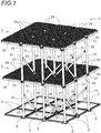
- the three-dimensional structure (1) of the invention comprises unitary modules (2) which are mutually assembled in juxtaposition to form a first level to be placed on the ground, and then superimposed to form the upper levels.
- the three-dimensional structure (1) of the invention comprises bases (3) intended to equip the underside of the unitary modules (2) and intended to be laid on the floor. soil substantially horizontally in the bottom of the dug basin where the three-dimensional structure (1) is to be assembled.
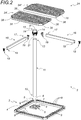
- Such a base (3) is represented in the unitary state on the figure 2 .
- It comprises at least one recess (4) for passing water and is preferably in the form of a generally rectangular frame and preferentially square.
- Each base (3) and also comprises at least one receiving housing (5), preferably only one, in its upper face.
- the receiving housing (5) is provided in a corner of said frame.
- This receiving housing (5) is preferably in the form of a cylindrical housing adapted to receive a vertical tube in its upper part.
- Each base (3) preferably comprises lateral attachment structures, for example clipping or interlocking structures, provided to allow mutual lateral assembly of the bases (3) with each other.
- each base (3) thus comprises hooking ramps on two consecutive lateral faces, while the two other consecutive lateral faces have complementary hooking ramps. provided so that bases (3) located side by side can be mutually assembled and immobilized by the engagement of the hooking ramp of a base (3) with the complementary hooking ramp of the base (3) neighbor.
- each base (3) is preferably equipped with a sole (6) having a lower flat and horizontal support surface mounted under said base (3) and secured thereto.
- the sole (6) is preferably provided at the receiving housing (5) shaped in the base (3).
- the receiving housing (5) preferably has a male piece (7) in its upper part, intended to be introduced into a complementary female part (8) formed in the lower part of the receiving housing (5) to be housed and immobilized.
- the receiving housing (5) is in the form of a cylindrical housing
- the lower part of said housing acts as a female part (8)
- the male part (7) of the sole (6) is preferably in the form of a cylindrical piece.
- the base (3) and the sole (6) are preferably made of injected plastic material and they comprise ribs (9) of reinforcement and stiffening.
- each base (3) is provided for housing and immobilizing the lower end (10) of a vertical tube (11).
- each unit module (2) comprises a single vertical tube (11), preferably of cylindrical shape.
- Each single vertical tube (11) is preferably in the form of a hollow tube with a round section of composite material, for example obtained by pultrusion of continuous glass fibers and resin.
- Each unitary module (2) also includes an end cap (12) adapted to be attached at the top end (13) of the vertical tube (11), the end cap (12) having a top receiver housing (5 ') shaped in its upper part and a lower receiving housing (5 ") shaped in its lower part, these receiving housing (5', 5") being substantially identical in shape to the receiving housing (5) of each base (3) ).
- each base (3) and the upper receiving housing (5 ') of each end fitting (12) are of complementary shape to that of the lower end (10) of the vertical tube (11). to receive the lower end (10) of a vertical tube (11) in a snug fit.
- each end nozzle (12) is of complementary shape to that of the upper end (13) of the vertical tube (11) to be mounted in the upper part of the vertical tube ( 11).
- each end piece (12) is preferably in the form of a cylindrical piece, and its receiving receptacles (5 ', 5 ") as well as the receiving receptacle (5) ) of each base (3) are also preferably cylindrical.
- each end cap (12) has at least two beam mounting bearings (14) which extend radially outwardly from said end cap (12).
- Each end piece (12) preferably comprises four beam mounting bearings (14) evenly distributed in a cross at an angle of 90 ° to each other on the periphery of said end piece (12).
- Each end piece (12) is preferably obtained by plastic injection. It preferably comprises ribs (15) of reinforcement and stiffening. These reinforcing ribs (15) and stiffening are preferably located around each support bearing (14) beam to strengthen them.
- Each unitary module (2) further comprises at least two horizontal beams (16) whose first end (17) is fixed to a beam mounting bearing (14) of the vertical tube (11), while its other end (18) ) is intended to be fixed to a beam mounting bearing (14) of a vertical tube (11) of another adjacent unitary module (2), said beam (16) being positioned horizontally between the two vertical tubes (11). ) thus connected.
- each horizontal beam (16) preferably comprises a beam attachment end (19) secured to each of its ends (17, 18) and adapted to cooperate with a beam mounting bearing (14) of an end piece (12).
- Each horizontal beam (16) thus makes it possible to connect two vertical tubes (11) at their respective end-piece (12) as shown in the drawings.
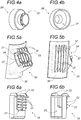
- Figures 16a and 16b In these figures, each beam mounting bearing (14) has an opening (20) in its upper part, in which is introduced a projecting portion (21) provided in each of the attachment pieces (19) beam.
- Each horizontal beam (16) is preferably in the form of a hollow tube of rectangular section of composite material, for example obtained by pultrusion of continuous glass fibers and resin.
- each beam attachment piece (19) is preferably made of an injected plastics material and has reinforcement and stiffening ribs (22). It has a receiving hollow portion (23) for mounting in tight fit and / or welding on the free end of a beam (16).
- Each unit module (2) finally comprises at least one grid (24) positioned on the horizontal beams (16) located to form a circulation floor.
- the grid (24) is generally rectangular in shape and preferably square. It may be in one piece, or in several parts (24 ', 24 ") juxtaposed
- the grid (24) is preferably made of injected plastic material.
- the grid (24) is preferably in the form of a honeycomb structure designed to pass water and having a planar upper face to serve as a circulation floor for those responsible for assembling the three-dimensional structure (1) of the invention.
- Each grid (24) to include one or more inserts (25) for reinforcement and stiffening, each designed to be introduced into a receiving housing (26) shaped in the body of the grid (24).
- the main role of these inserts (25) is to strengthen the flexural strength of the grids (24).
- each reinforcing and stiffening insert (25) is preferably in the form of a hollow tube of rectangular section of composite material, for example obtained by pultrusion of continuous glass fibers and resin.
- certain unitary modules (2) may also comprise one or more oblique crutches (27) for stiffening. These oblique crutches (27) are preferably provided at the level of the unit modules (2) located at the periphery of the three-dimensional structure (1) to reinforce its mechanical strength, especially with respect to the lateral thrust exerted by the earth mass which surround it when the pit where the three-dimensional structure (1) is filled with earth.
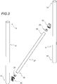
- each oblique stand (27) is preferably in the form of a hollow tube of round section of composite material, for example obtained by pultrusion of continuous glass fibers and resin.
- Each oblique crutch (27) is provided to be fixed in a manner inclined on two vertical tubes (11) to connect and immobilize each other.
- each oblique leg (27) comprises a fixing piece (29) of stand provided to cooperate in fixing and immobilization with a bearing (30) of support provided on each two vertical tubes (11) to be connected.
- An oblique crutch (27) equipped with a fixing piece (29) of crutch at each of its ends (28) is illustrated on the figure 13 .
- Each oblique crutch (27) is preferably symmetrical and its two ends (28) are identical.
- each attachment piece (29) of stand is preferably made of injected plastic material. It has a receiving hollow portion (31) for mounting in close fit and / or welding on the free end (28) of an oblique stand (27), and a projecting portion (32) to be received immobilized in a receiving member (33) provided in each support bearing (30) of stand, this receiving member (33) preferably have a lateral opening (34) for receiving the projecting portion (32) of a mouthpiece fixing (29) crutch (see Figures 15a and 15b ) and clipping means (37) thereof.
- each support bearing (30) for stand is preferably made of injected plastic material. It has reinforcement and stiffening ribs (35), a receiving part (33) oriented preferably inclined at the same angle of inclination of the oblique legs (27), and a base (36) intended to be secured to the outer periphery.
- the base (36) preferably has a complementary concavity of the external shape of the vertical tube (11).
- a first support bearing (30) of support is preferably provided in the lower part of a first vertical tube (11), while a second support bearing (30) of crutches is preferably provided in the upper half of a second vertical tube (11) adjacent.
- each oblique crutch (27) is preferably approximately 45 °.
- the same vertical tube (11) can be equipped with one or more support bearings (30) of stand as required for the three-dimensional structure (1).
- the gate (24) of the unitary module (2) of the invention is preferably of substantially square shape, with a width and a length of about 1 meter, which provides sufficient mechanical strength for a large area.
- the grid (24) preferably has a width and a length of between 50 centimeters and 150 centimeters.
- each vertical tube (11) of the unitary module (2) of the invention may be variable, as adapted to the height of the buried basin infiltration, retention and / or storage of rainwater provided.
- these tubes can be up to 2 meters high without presenting a risk of excessive bending. They preferably have a length of between 1.5 and 2 meters, and more preferably a height of about 1.6 meters, which allows operators to circulate under the grids (24).
- the three-dimensional structure (1) may comprise a closing geogrid (not shown) which surrounds its periphery and whose mesh is dimensioned so as to prevent the earth from penetrating laterally inside the three-dimensional structure ( 1).
- an engineer or a technician dimensions the three-dimensional structure (1) and determines the number, the position and the orientation of the different oblique stiffening crutches (27) required for the buried basin. infiltration, retention and / or storage of rainwater. It thus provides a specific assembly plan for this three-dimensional structure (1) to the assemblers responsible for assembling the three-dimensional structure (1) on site.
- vertical tubes are equipped bearings (30) for fixing the stand.
- the different end pieces (12, 19, 29) can be pre-mounted on their respective tubular element (11, 16, 27).
- the inserts (25) for reinforcement and stiffening can be introduced at the factory into each grid (24), and the flanges (6) can be mounted on the underside of each base (3).
- the assemblers After transportation and unloading on site of the various means constituting the three-dimensional structure (1), whereas the receiving pit for this three-dimensional structure (1) has already been dug and flattened, the assemblers begin by positioning the bases (3) on the ground, each being preferably equipped with a sole (6). These bases (3) are mutually assembled and immobilized by assembling their hooking ramps and their respective complementary hooking ramps. They then form a kind of flat and water permeable pavement provided in the bottom of the basin which will serve as a base for the unit modules (2) to be assembled on it.
- a vertical tube (11) is then housed and immobilized by its lower end (10) in the receiving housing (5) of each base (3), and an end piece (12) engaged at the upper end. (13) of each vertical tube (11) if this had not been done in the factory (see figure 7 ).
- the assemblers then fix the oblique stiffening legs (27) by clipping between the vertical tubes (11) where necessary.
- Securing by securing an oblique stiffening stand (27) on a vertical tube (11) is represented on the Figures 15a and 15b .
- An oblique stiffening stand (27) immobilized between two vertical tubes (11) is also shown in profile on the Figures 10 and 11 .
- the assemblers also fix the horizontal beams (16), with one beam (16) between each pair of adjacent vertical tubes (11) so as to form a horizontal support frame for the grids (24), this frame being preferentially similar in shape to that of the base (3) located below and located in the same vertical volume.
- Securing by clipping of a beam (16) on the end piece (12) of a vertical tube (11) is represented on the Figures 16a and 16b .
- the grids (24) equipped with inserts (25) are then placed on these frames.
- Each grid (24) is preferably immobilized in wedging between four horizontal beams (16) forming a frame by the support of a groove (38) on the upper edge of the beams (16), this groove (38) being shaped in the lower part of the perimeter of each grid (24) (see figure 8 ).
- the grids (24) of the already assembled unitary modules (2) form a floor on which the assemblers can freely move to assemble the unit modules ( 2) in order to add an additional level of unit modules (2) in height for the three-dimensional structure (1).
- This assembly is very similar to the previous one. The only difference lies in the fact that a vertical tube (11) is not mounted in the receiver housing (5) of the bases (3), but that a vertical tube (11) is housed and immobilized in the receiving housing bottom (5 ") of each end piece (12) of the vertical tubes (11) below.
- the three-dimensional structure (1) according to the invention may comprise several stages.
- the end caps (12) in the upper part of the vertical tubes (11) allow to insert the vertical tubes (11) of the next stage.
- figure 1 illustrates a three-dimensional structure (1) comprising only two levels of unitary modules (2), it may comprise any number, or possibly a single level.
- each unitary module (2) the vertical tube (11), the end piece (12), each beam (16), each grid (24), each fixing bearing (30) crutch and each stiffening stand (27) are preferentially dissociated means, that is to say separate means which are provided to be mutually assembled for mounting the three-dimensional structure (1).
- none of these means is formed in one piece with another of these means.
Landscapes
- Engineering & Computer Science (AREA)
- Health & Medical Sciences (AREA)
- Life Sciences & Earth Sciences (AREA)
- Hydrology & Water Resources (AREA)
- Public Health (AREA)
- Water Supply & Treatment (AREA)
- Environmental & Geological Engineering (AREA)
- Sewage (AREA)
Applications Claiming Priority (1)
| Application Number | Priority Date | Filing Date | Title |
|---|---|---|---|
| FR1853801A FR3080867B1 (fr) | 2018-05-03 | 2018-05-03 | Structure tridimensionnelle a monter pour combler un bassin enterre de retention des eaux de pluie |
Publications (1)
| Publication Number | Publication Date |
|---|---|
| EP3564452A1 true EP3564452A1 (de) | 2019-11-06 |
Family
ID=62751148
Family Applications (1)
| Application Number | Title | Priority Date | Filing Date |
|---|---|---|---|
| EP19164875.7A Withdrawn EP3564452A1 (de) | 2018-05-03 | 2019-03-25 | Montierbare 3d-struktur zum auffüllen eines regenwasser-rückhaltebeckens im boden |
Country Status (2)
| Country | Link |
|---|---|
| EP (1) | EP3564452A1 (de) |
| FR (1) | FR3080867B1 (de) |
Citations (8)
| Publication number | Priority date | Publication date | Assignee | Title |
|---|---|---|---|---|
| JPH10195937A (ja) * | 1996-12-28 | 1998-07-28 | Takiron Co Ltd | 地下貯水槽等に用いる充填部材 |
| JP2003278193A (ja) * | 2002-03-22 | 2003-10-02 | Takiron Co Ltd | 地下貯水槽 |
| WO2006038602A1 (ja) * | 2004-10-04 | 2006-04-13 | Toyo Tire & Rubber Co., Ltd. | 雨水貯留構造用部材とこれを用いた雨水貯留構造物 |
| WO2011017766A1 (en) * | 2009-08-14 | 2011-02-17 | Gooden, Rebecca | A modulated structural cell for supporting a tree root network |
| KR20110078111A (ko) * | 2009-12-30 | 2011-07-07 | 주식회사 한설그린 | 정수(淨水) 기능이 구비된 조립식(組立式) 우수(雨水)저류(貯留) 블록 |
| US20130152499A1 (en) * | 2011-12-19 | 2013-06-20 | John E. Kriekemeier | Water retention/detention structure formed from identical panels |
| WO2014161039A1 (en) * | 2013-04-04 | 2014-10-09 | Strata Innovations Pty Limited | A modular cell and matrix for supporting a load bearing feature |
| WO2017217846A1 (en) * | 2016-06-17 | 2017-12-21 | Pipelife Nederland B.V. | Interlocking panels for drainage structures |
-
2018
- 2018-05-03 FR FR1853801A patent/FR3080867B1/fr active Active
-
2019
- 2019-03-25 EP EP19164875.7A patent/EP3564452A1/de not_active Withdrawn
Patent Citations (8)
| Publication number | Priority date | Publication date | Assignee | Title |
|---|---|---|---|---|
| JPH10195937A (ja) * | 1996-12-28 | 1998-07-28 | Takiron Co Ltd | 地下貯水槽等に用いる充填部材 |
| JP2003278193A (ja) * | 2002-03-22 | 2003-10-02 | Takiron Co Ltd | 地下貯水槽 |
| WO2006038602A1 (ja) * | 2004-10-04 | 2006-04-13 | Toyo Tire & Rubber Co., Ltd. | 雨水貯留構造用部材とこれを用いた雨水貯留構造物 |
| WO2011017766A1 (en) * | 2009-08-14 | 2011-02-17 | Gooden, Rebecca | A modulated structural cell for supporting a tree root network |
| KR20110078111A (ko) * | 2009-12-30 | 2011-07-07 | 주식회사 한설그린 | 정수(淨水) 기능이 구비된 조립식(組立式) 우수(雨水)저류(貯留) 블록 |
| US20130152499A1 (en) * | 2011-12-19 | 2013-06-20 | John E. Kriekemeier | Water retention/detention structure formed from identical panels |
| WO2014161039A1 (en) * | 2013-04-04 | 2014-10-09 | Strata Innovations Pty Limited | A modular cell and matrix for supporting a load bearing feature |
| WO2017217846A1 (en) * | 2016-06-17 | 2017-12-21 | Pipelife Nederland B.V. | Interlocking panels for drainage structures |
Also Published As
| Publication number | Publication date |
|---|---|
| FR3080867A1 (fr) | 2019-11-08 |
| FR3080867B1 (fr) | 2020-10-23 |
Similar Documents
| Publication | Publication Date | Title |
|---|---|---|
| CH714202A1 (fr) | Système de construction pour un module d'un bâtiment. | |
| CA1287724C (fr) | Systeme de construction modulaire d'une structure couverte de grande section et son procede de construction | |
| EP1112425B1 (de) | Verfahren und vorrichtung zum zusammenbau von bauelementen von wasserbecken, wie z.b. schwimmbecken | |
| FR3127969A1 (fr) | Dispositif modulaire de pose d’un appareillage sur une plateforme | |
| FR3080867A1 (fr) | Structure tridimensionnelle a monter pour combler un bassin enterre de retention des eaux de pluie | |
| EP4417771A1 (de) | Verfahren zur herstellung einer modularen selbsttragenden struktur zur herstellung eines beckens, wie eines schwimmbeckens, bausatz und becken | |
| FR2668029A3 (fr) | Dispositif pour recouvrir les fosses de plantation d'arbres dans les surfaces de circulation. | |
| FR2743832A1 (fr) | Poteau en beton arme pour structure porteuse de batiment et structure de batiment comportant de tels poteaux | |
| EP3619379B1 (de) | Satz von strukturelementen zur bildung eines mehrgeschossigen, oberirdischen parkhauses und entsprechendes mehrgeschossiges oberirdisches parkhaus | |
| FR2760482A1 (fr) | Coffrage pour l'execution de dalles ou planchers en beton faisant application d'un systeme portant modulaire | |
| FR3080868A1 (fr) | Element unitaire tridimensionnel destine a combler un bassin enterre de retention des eaux de pluie | |
| EP1371785B1 (de) | Vorgefertigtes Element für ein Mannloch und Mannloch | |
| FR3133400A1 (fr) | Structure de piscine hors sol et son procede de montage | |
| FR2565278A1 (fr) | Ensemble d'elements de construction pour l'edification de murs par post-contrainte | |
| WO2015186103A1 (fr) | Structure metallique pour un batiment et batiment, par exemple destine a l'elevage d'animaux, muni d'une telle structure | |
| FR2746124A1 (fr) | Jeu d'elements pour conformer de maniere variable des dispositifs de support et/ou de separation du batiment | |
| EP0005575A1 (de) | Vorgefertigter Schornstein | |
| CH694702A5 (fr) | Construction modulaire comportant au moins quatre montants verticaux et des contreventements. | |
| FR2743100A1 (fr) | Mur de soutenement ou de stockage d'un materiau ou produit quelconque | |
| WO2012069431A1 (fr) | Serre comprenant au moins un cheneau dispose au sommet de poteaux et fixe par vissage a des prolongements en hauteur des poteaux | |
| FR2850416A1 (fr) | Panneau pour la realisation d'ouvrages de genie civil, et notamment de piscines et procede de construction utilisant de tels panneaux | |
| FR2648197A1 (fr) | Dispositif de fixation d'elements en bois entre eux pour realiser une structure modulable tel que notamment un abri pour intemperies | |
| CH356900A (fr) | Ensemble d'éléments préfabriqués pour l'érection d'une construction | |
| EP0006055B1 (de) | Aus vorgefertigten Elementen bestehende Raumzelle | |
| FR3062149A1 (fr) | Structure de piscine |
Legal Events
| Date | Code | Title | Description |
|---|---|---|---|
| PUAI | Public reference made under article 153(3) epc to a published international application that has entered the european phase |
Free format text: ORIGINAL CODE: 0009012 |
|
| AK | Designated contracting states |
Kind code of ref document: A1 Designated state(s): AL AT BE BG CH CY CZ DE DK EE ES FI FR GB GR HR HU IE IS IT LI LT LU LV MC MK MT NL NO PL PT RO RS SE SI SK SM TR |
|
| AX | Request for extension of the european patent |
Extension state: BA ME |
|
| STAA | Information on the status of an ep patent application or granted ep patent |
Free format text: STATUS: THE APPLICATION IS DEEMED TO BE WITHDRAWN |
|
| 18D | Application deemed to be withdrawn |
Effective date: 20200603 |