EP3564457A1 - Zwischenkoppler zur betonbewehrung - Google Patents
Zwischenkoppler zur betonbewehrung Download PDFInfo
- Publication number
- EP3564457A1 EP3564457A1 EP19172644.7A EP19172644A EP3564457A1 EP 3564457 A1 EP3564457 A1 EP 3564457A1 EP 19172644 A EP19172644 A EP 19172644A EP 3564457 A1 EP3564457 A1 EP 3564457A1
- Authority
- EP
- European Patent Office
- Prior art keywords
- chuck
- coupler
- threads
- external threads
- cover
- Prior art date
- Legal status (The legal status is an assumption and is not a legal conclusion. Google has not performed a legal analysis and makes no representation as to the accuracy of the status listed.)
- Granted
Links
Images






Classifications
-
- E—FIXED CONSTRUCTIONS
- E04—BUILDING
- E04C—STRUCTURAL ELEMENTS; BUILDING MATERIALS
- E04C5/00—Reinforcing elements, e.g. for concrete; Auxiliary elements therefor
- E04C5/08—Members specially adapted to be used in prestressed constructions
- E04C5/12—Anchoring devices
- E04C5/122—Anchoring devices the tensile members are anchored by wedge-action
-
- E—FIXED CONSTRUCTIONS
- E04—BUILDING
- E04C—STRUCTURAL ELEMENTS; BUILDING MATERIALS
- E04C5/00—Reinforcing elements, e.g. for concrete; Auxiliary elements therefor
- E04C5/01—Reinforcing elements of metal, e.g. with non-structural coatings
- E04C5/02—Reinforcing elements of metal, e.g. with non-structural coatings of low bending resistance, i.e. of essentially one-dimensional [1D] or two-dimensional [2D] extent
-
- E—FIXED CONSTRUCTIONS
- E04—BUILDING
- E04C—STRUCTURAL ELEMENTS; BUILDING MATERIALS
- E04C5/00—Reinforcing elements, e.g. for concrete; Auxiliary elements therefor
- E04C5/16—Auxiliary parts for reinforcements, e.g. connectors, spacers, stirrups
- E04C5/161—Protective caps for the ends of reinforcing bars
-
- E—FIXED CONSTRUCTIONS
- E04—BUILDING
- E04C—STRUCTURAL ELEMENTS; BUILDING MATERIALS
- E04C5/00—Reinforcing elements, e.g. for concrete; Auxiliary elements therefor
- E04C5/16—Auxiliary parts for reinforcements, e.g. connectors, spacers, stirrups
- E04C5/162—Connectors or means for connecting parts for reinforcements
- E04C5/163—Connectors or means for connecting parts for reinforcements the reinforcements running in one single direction
-
- E—FIXED CONSTRUCTIONS
- E04—BUILDING
- E04C—STRUCTURAL ELEMENTS; BUILDING MATERIALS
- E04C5/00—Reinforcing elements, e.g. for concrete; Auxiliary elements therefor
- E04C5/16—Auxiliary parts for reinforcements, e.g. connectors, spacers, stirrups
- E04C5/162—Connectors or means for connecting parts for reinforcements
- E04C5/163—Connectors or means for connecting parts for reinforcements the reinforcements running in one single direction
- E04C5/165—Coaxial connection by means of sleeves
Definitions
- the present application relates to a coupler for joining reinforcing tendons in concrete.
- Concrete is capable of withstanding significant compressive loads, but is more susceptible to failure when subjected to significant tensile loads.
- concrete structures are often reinforced with steel bars, cables, or similar to enhance the structure's ability to withstand tensile forces.
- a coupler is disclosed.
- the coupler includes a first chuck and a second chuck.
- the coupler also includes a coupler body including a first end, a second end, and a passageway extending between the first end and the second end, the first end secured to the first chuck, the second end secured to the second chuck.
- the coupler includes a cover, the cover extending along and enclosing the second chuck.
- the coupler includes a cup, the cup covering an end surface of the first chuck, the cup in sealing engagement with the cover.
- a system includes an intermediate anchor and a coupler.
- the coupler includes a first chuck adapted to receive an end of a first tendon, the first chuck including first external threads and a second chuck adapted to receive an end of a second tendon, the second chuck including second external threads, the second external threads having a reverse orientation relative to the first external threads.
- the coupler also includes a coupler body including a first end, a second end, and a passageway extending between the first end and the second end, the first end including first internal threads configured to engage the first external threads, the second end including second internal threads configured to engage the second external threads, whereby rotation of the coupler body in a first direction about the longitudinal axis of the coupler body simultaneously advances both the first chuck and the second chuck into the passageway.
- the coupler further includes a cover extending along the second chuck.
- FIG. 1 illustrates reinforced concrete structure 1 including adjacent portions 10a, 10b.
- Portions 10a, 10b may be formed in a framing structure 14.
- First and second tendons 18a, 18b may extend through portions 10a, 10b.
- First anchor 22 may be positioned at first end 24 of reinforced concrete structure 1 (i.e., at an end of the first portion 10a).
- One end of first tendon 18a may be secured to first anchor 22.
- First tendon 18a may extend through first portion 10a to intermediate wall or partition 26 positioned between portions 10a, 10b.
- Intermediate anchor 30 may be positioned adjacent partition 26, and an opposite end of first tendon 18a may extend through intermediate anchor 30. The opposite end of first tendon 18a may be secured to one end of coupler 34.
- second tendon 18b may be secured to an opposite end of coupler 34, and another end of second tendon 18b may be extended through second portion 10b of concrete to another partition or an end wall 38 (i.e., an end of reinforced concrete structure 1). The other end of second tendon 18b may be secured to second anchor 42 positioned adjacent to end wall 38.
- reinforced concrete structure 1 may include additional portions positioned sequentially in an abutting (e.g., end-to-end) relationship, and/or may include more than two tendons 18a, 18b. While FIG. 1 shows a cross-section view of reinforced concrete structure 1 including one set of tendons for simplicity, reinforced concrete structure 1 may include multiple tendons positioned in parallel to tendons 18a, 18b, and/or may include multiple tendons extending in other directions through portions 10a, 10b.
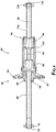
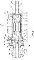
- FIGS. 2-4 illustrate an assembly of intermediate anchor 30 and coupler 34.
- intermediate anchor 30 includes core 50 ( FIG. 4 ) and encapsulation 54 covering core 50.
- core 50 may be formed from a metal (e.g., cast steel, ductile iron, etc.), and encapsulation 54 may be formed from a polymer (e.g., high-density polyethylene).
- Intermediate anchor 30 further includes bore 58 and flange 62. Bore 58 extends along an axis 66 of core 50 and may receive a tendon such as, for example tendon 18a ( FIG. 1 ).
- Flange 62 extends laterally (e.g., substantially perpendicular to) to axis 66 and provides a bearing surface against the concrete.
- a portion of encapsulation 54 extends beyond core 50 and along axis 66, defining encapsulation tail portion 68.
- Seal 72 may be positioned adjacent an end of encapsulation tail portion 68, and locknut 76 may exert a compressive force around outer surface of seal 72 and/or encapsulation tail portion 68 to provide a seal against a sheathed portion of first tendon 18a.
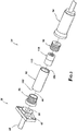
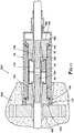
- coupler 34 may include coupler body 82, first chuck 86, second chuck 90, and cover 94.
- coupler body 82 has first end 102 and second end 106 opposite first end 102, and passageway 110 ( FIG. 4 ) that extends through coupler body 82 from first end 102 to second end 106. Passageway 110 may be aligned with axis 66.
- First chuck 86 may be secured to first end 102 of coupler body 82 (e.g., by threaded engagement), and second chuck 90 may be secured to second end 106 of coupler body 82 (e.g., by threaded engagement).
- first chuck 86 and second chuck 90 are shown as being in threaded arrangement with first end 102 and second end 106 respectively, both or either may be secured by any other means known in the art, including, for example and without limitation, press fitting, mechanical welding, chemical welding, friction welding, thermal coupling or welding, electrical welding, optical welding, or beam-energy welding.
- spacer 118 may be slidably received within passageway 110 between first chuck 86 and second chuck 90. Spacer 118 may ensure that first chuck 86 and second chuck 90 are not over-threaded into coupler body 82.
- spacer 118 may be formed as two pieces joined together, for example, by a snap fit, or by any other means known in the art, including, for example and without limitation, press fitting, mechanical welding, chemical welding, friction welding, thermal coupling or welding, electrical welding, optical welding, or beam-energy welding.
- cover 94 extends along and encloses the outside of coupler body 82 and first chuck 86 and second chuck 90.
- Cover 94 may be formed from the same material as encapsulation 54 of intermediate anchor 30, although in other embodiments, cover 94 may be formed from a different material than that of encapsulation 54.
- Cover 94 may include tubular portion 122 and cover tail portion 126 extending from tubular portion 122.
- Tubular portion 122 receives coupler body 82 and first chuck 86 and second chuck 90, although cover 94 may include additional spaces 130 ( FIG. 5 ) to permit some movement between cover 94 and coupler body 82 and first chuck 86 and second chuck 90.
- Cover tail portion 126 extends along axis 66, and seal 132 may be positioned adjacent an end of cover tail portion 126.
- Locknut 134 exerts a compressive force around an outer surface of seal 132 and/or cover tail portion 126 to provide a seal against a sheathed portion of second tendon 18b ( FIG. 1 ).
- first chuck 86 may include first flange 138, first external threaded portion 142 extending from one side of first flange 138, and cup 146 covering an opposite side of first flange 138.
- First chuck 86 may further include first tapered chamber 150 for receiving wedges (not shown) to secure tendon 18a ( FIG. 1 ) relative to first chuck 86.
- First external threaded portion 142 may be engaged with a first internal threaded portion 154 of first end 102 of coupler body 82, such as by threading.
- First external threaded portion 142 may engage first internal threaded portion 154 until first flange 138 abuts an end surface of coupler body 82 or spacer 118.
- Cup 146 may include hole 158 therethrough, aligned with axis 66 such that an end of tendon 18a ( FIG. 1 ) may pass through cup 146 and into first tapered chamber 150.
- cup 146 may be formed from the same material as cover 94. In other embodiments, cup 146 may be formed from a different material.
- a non-limiting material for cup 146 may be high density polypropylene.
- Peripheral portion 162 of cup 146 may extend over a lateral portion of first flange 138, and peripheral portion 162 may be sealed against an internal surface of cover 94, such as by O-ring 166. Planar portion 170 of cup 146 abuts end surface 174 of intermediate anchor 30. As shown in FIGS.
- planar portion 170 of cup 146 may include protrusions 182.
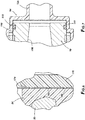
- tendon 18a When tendon 18a is to be tensioned and fixed with wedges, the tension force draws first chuck 86 against intermediate anchor 30. As a result, protrusions 182 are pressed into encapsulation 54 of intermediate anchor 30 ( FIG. 8 ).
- sealing protrusion 184 FIG. 8 ) may be positioned around an inner surface of hole 158.
- second chuck 90 may include second flange 190 and second external threaded portion 194 extending from one side of second flange 190. Second chuck 90 may further include second tapered chamber 198 for receiving wedges to secure tendon 18b ( FIG. 1 ) relative to second chuck 90. Second external threaded portion 194 may be threadably engaged with second internal threaded portion 202 of second end 106 of coupler body 82.
- first threaded portions 142, 154 may each comprise multi-lead threads (for example, triple-lead threads), and second threaded portions 194, 202 may also each comprise multi-lead threads.
- First chuck 86 and second chuck 90 may be threaded into the coupler body 82 more quickly (i.e., in fewer rotations).
- the threads of second external threaded portion 194 may have a direction that is in reverse orientation with respect to the threads of first external threaded portion 142 of first chuck 86. For example, if first external threaded portion 142 includes right-hand threads, second external threaded portion 194 may include left-hand threads.
- peripheral portion 206 of second flange 190 may be sealed , such as by O-ring 210, against an inner surface of cover 94.
- tendon 18a may be first secured to first anchor 22.
- Intermediate anchor 30 may be positioned adjacent partition 26 and cup 146 may abut end surface 174 of intermediate anchor 30.
- First tendon 18a may be covered in a sheath and extended through intermediate anchor 30 and cup 146.
- a pocket former may be positioned adjacent intermediate anchor 30 and cup 146 to prevent or restrict concrete from completely embedding intermediate anchor 30 during formation of first concrete portion 10b.
- cup 146 may act as a grout-exclusion plug during concrete placement. Concrete may be then poured into first portion 10a.
- first chuck 86 may be positioned over first tendon 18a and a sheath-cutting tool may remove a portion of the tendon sheath from the end.
- Wedges may be positioned in first tapered chamber 150 and tendon 18a may be tensioned such as by a hydraulic tensioner. As tension is applied, the wedges are forced into first tapered chamber 150 to secure tendon 18a within first chuck 86. An excess portion of tendon tail (i.e., the portion extending beyond a minimum protruding from first chuck 86) may be removed.
- Second tendon 18b extends through second chuck 90, and wedges may be positioned in second tapered chamber 198 to secure the end of second tendon 18b to second chuck 90.
- Spacer 118 may be positioned within coupler body 82 of coupler 34, and coupler body 82 may be positioned between first chuck 86 and second chuck 90.
- coupler body 82 may be rotated in a single direction to simultaneously advance both first chuck 86 and second chuck 90 into coupler body 82. Coupler body 82 and chucks 86, 90 join or splice tendons 18a, 18b.
- the tensioning force exerted on tendons 18a, 18b may be transmitted through intermediate anchor 30, through first chuck 86 and second chuck 90 via the wedges, and through coupler body 82 connecting first chuck 86 and second chuck 90.
- Cover 94 may be positioned over coupler body 82 and first chuck 86 and second chuck 90, and sealed against cup 146 on one end and against the sheathed tendon 18b on the other end.
- tendon 18b may extend through second anchor 42 on an opposite end of second portion 10b. If second portion 10b is to be the final concrete portion to be cast for reinforced concrete structure 1, second tendon 18b may be tensioned, cut, and secured to second anchor 42 after concrete portion 10b is poured and set. Otherwise, the process may be repeated to connect tendon 18b to an additional tendon extending through additional concrete sections.
- Cover 94 may seal against cup 146, which in turn seals against the sheath of tendon 18a. Tendons 18a, 18b and components of coupler 34 are sealed against moisture. Intermediate anchor 30 provides a temporary load bearing function until second tendon 18b can be joined and tensioned, but tendons 18a, 18b and coupler components may remain covered and sealed. The sealing of the internal components may be independent of an interface between intermediate anchor 30 and coupler 34.
- FIG. 9 illustrates an intermediate anchor 430 and coupler 434 according to another embodiment of the present disclosure.
- intermediate anchor 430 does not include an encapsulation, but only core 450.
- Washer 452 may be positioned adjacent end surface 574 of intermediate anchor 430, between intermediate anchor 430 and cup 534.
- cup 534 includes throat 572 that extends through a portion of first chuck 86, toward first tapered chamber 150 without extending into first tapered chamber 150.
- Throat 572 may include one or more sealing protrusions 576 to engage an outer surface of sheath 578 of tendon 18a and prevent or restrict moisture from penetrating into the unsheathed portion of tendon 18a in first tapered chamber 150 where wedges 188 engage tendon 18a.
- cup 534 may include a neck 580 extending into a chamber of intermediate anchor 430 and sealing against sheath 578 of tendon 18a.
- FIG. 11 illustrates yet another embodiment of an intermediate anchor 830 and coupler 834.
- Intermediate anchor 830 may comprise an unencapsulated load plate against which first cup 934 may be compressed by first chuck 86.
- an end of cover 94 extends into abutment with the unencapsulated load plate.
- First cup 934 may be positioned on first flange 138 on first chuck 86 and a second cup 986 may be positioned on a second flange 190 on second chuck 90.
- Each cup 934, 986 may include an inner annular surface that may be sealed against an end surface of coupler body 82, such as by O-rings 166.
- Each cup 934, 986 may also include neck 980.
- FIGS. 12-14 illustrate yet another embodiment of an intermediate anchor 1230 and coupler 1234 connecting tendons 18a, 18b having sheaths 1378.
- Intermediate anchor 1230 may include core 1250 that may be encapsulated.
- first chuck 86 may engage directly against end surface 1374 of core 1250, and a portion of encapsulation 1254a may extend beyond the end of core 1250 and over the coupler body 1282 of coupler 1234.
- An end of cover 1294 adjacent to first chuck 86 may be sealed, for example, by an O-ring 166, against an outer surface of portion of encapsulation 1254a.
Landscapes
- Engineering & Computer Science (AREA)
- Architecture (AREA)
- Civil Engineering (AREA)
- Structural Engineering (AREA)
- Reinforcement Elements For Buildings (AREA)
- Rod-Shaped Construction Members (AREA)
- Piles And Underground Anchors (AREA)
Applications Claiming Priority (1)
| Application Number | Priority Date | Filing Date | Title |
|---|---|---|---|
| US201862666530P | 2018-05-03 | 2018-05-03 |
Publications (2)
| Publication Number | Publication Date |
|---|---|
| EP3564457A1 true EP3564457A1 (de) | 2019-11-06 |
| EP3564457B1 EP3564457B1 (de) | 2023-07-05 |
Family
ID=66554124
Family Applications (1)
| Application Number | Title | Priority Date | Filing Date |
|---|---|---|---|
| EP19172644.7A Active EP3564457B1 (de) | 2018-05-03 | 2019-05-03 | Zwischenkoppler zur betonbewehrung |
Country Status (4)
| Country | Link |
|---|---|
| US (1) | US10745916B2 (de) |
| EP (1) | EP3564457B1 (de) |
| CA (1) | CA3042409C (de) |
| ES (1) | ES2952152T3 (de) |
Cited By (1)
| Publication number | Priority date | Publication date | Assignee | Title |
|---|---|---|---|---|
| US11035122B1 (en) | 2020-03-18 | 2021-06-15 | Felix Sorkin | Intermediate concrete anchor system with cap |
Families Citing this family (6)
| Publication number | Priority date | Publication date | Assignee | Title |
|---|---|---|---|---|
| US20200040593A1 (en) * | 2017-01-17 | 2020-02-06 | Danmarks Tekniske Universitet | A reinforcement system and a method of reinforcing a structure with a tendon |
| US10995494B2 (en) * | 2019-05-28 | 2021-05-04 | Felix Sorkin | Apparatus for repairing a tension member |
| US11255096B2 (en) * | 2019-11-25 | 2022-02-22 | Lugo Designs LLC | Sealing connector for post tensioned anchor system |
| CN114482413B (zh) * | 2022-02-16 | 2022-11-08 | 浙江大学 | 一种插杆式快速连接装置 |
| US12054947B1 (en) * | 2024-01-08 | 2024-08-06 | King Faisal University | Multi-layer wedge anchorage for FRP plates and FRP tendons |
| WO2026072841A1 (en) * | 2024-09-25 | 2026-04-02 | General Technologies, Inc. | Slab anchor encapsulation assembly |
Citations (4)
| Publication number | Priority date | Publication date | Assignee | Title |
|---|---|---|---|---|
| US3850535A (en) * | 1972-09-11 | 1974-11-26 | Hewlett Machines Works | Connecting means and method for forming reinforcing rod connection |
| US4318256A (en) * | 1978-05-16 | 1982-03-09 | Boonman Cornelis Johannes F | Anchor construction for prestressing members |
| WO1992008019A1 (fr) * | 1990-10-29 | 1992-05-14 | Marcel Arteon | Dispositif de liaison pour reunir bout a bout deux barres |
| US6151850A (en) * | 1999-04-26 | 2000-11-28 | Sorkin; Felix L. | Intermediate anchorage system utilizing splice chuck |
Family Cites Families (51)
| Publication number | Priority date | Publication date | Assignee | Title |
|---|---|---|---|---|
| CH665444A5 (de) * | 1985-01-17 | 1988-05-13 | Losinger Ag | Zwischenankeranordnung zum vorspannen von bauteilen, die in mehreren bauetappen erstellt werden, und ein verfahren zum herstellen einer solchen zwischenankeranordnung. |
| US4896470A (en) | 1988-04-21 | 1990-01-30 | Varitech Industries, Inc. | Tendon tensioning anchor |
| US5072558A (en) | 1988-04-21 | 1991-12-17 | Varitech Industries, Inc. | Post-tension anchor system |
| US4900193A (en) * | 1989-02-16 | 1990-02-13 | The Foundation Equipment Corporation | Concrete structural member splicing device |
| US5440842A (en) | 1992-12-09 | 1995-08-15 | Felix L. Sorkin | Sealed tendon-tensioning anchor system |
| US5720139A (en) | 1996-02-26 | 1998-02-24 | Sorkin; Felix L. | Method and apparatus for installing a multi-strand anchorage system |
| US5770286A (en) | 1996-04-10 | 1998-06-23 | Sorkin; Felix L. | Corrosion inhibitor retaining seal |
| US5755065A (en) | 1996-04-25 | 1998-05-26 | Sorkin; Felix L. | Method and apparatus for forming an anchorage of a post-tension system |
| US5749185A (en) | 1996-04-25 | 1998-05-12 | Sorkin; Felix L. | Method and apparatus for an intermediate anchorage of a post-tension system |
| US5701707A (en) | 1996-05-06 | 1997-12-30 | Sorkin; Felix L. | Bonded slab post-tension system |
| US5788398A (en) | 1996-07-09 | 1998-08-04 | Sorkin; Felix L. | Connector seal for an anchor and a corrosion-protection tube of a post-tension system |
| US6098356A (en) | 1998-11-03 | 2000-08-08 | Sorkin; Felix L. | Method and apparatus for sealing an intermediate anchorage of a post-tension system |
| US6012867A (en) | 1997-08-18 | 2000-01-11 | Sorkin; Felix L. | Multi-strand anchorage system with an anchor body for receiving a grout tube |
| US5839235A (en) | 1997-08-20 | 1998-11-24 | Sorkin; Felix L. | Corrosion protection tube for a post-tension anchor system |
| US6027278A (en) | 1998-01-15 | 2000-02-22 | Sorkin; Felix L. | Wedge-receiving cavity for an anchor body of a post-tension anchor system |
| US5897102A (en) | 1998-01-15 | 1999-04-27 | Sorkin; Felix L. | Pocketformer apparatus for a post-tension anchor system |
| US6023894A (en) | 1998-01-15 | 2000-02-15 | Sorkin; Felix L. | Anchor of a post-tension anchorage system with an improved cap connection |
| US6234709B1 (en) | 1998-01-15 | 2001-05-22 | Felix L. Sorkin | Wedge-receiving cavity with radiused edge for an anchor body of a post-tension anchor system |
| US6017165A (en) | 1998-01-15 | 2000-01-25 | Sorkin; Felix L. | Wedge-receiving cavity for an anchor body of a post-tension anchor system |
| US6176051B1 (en) * | 1999-04-26 | 2001-01-23 | Felix L. Sorkin | Splice chuck for use in a post-tension anchor system |
| AU768704B2 (en) * | 2000-03-02 | 2004-01-08 | Anderson Technology Corporation | PC steel stranded wire connection structure and construction method thereof |
| US6393781B1 (en) | 2000-03-13 | 2002-05-28 | Felix L. Sorkin | Pocketformer apparatus for a post-tension anchor system and method of using same |
| US6817148B1 (en) | 2000-08-28 | 2004-11-16 | Felix L. Sorkin | Corrosion protection seal for an anchor of a post-tension system |
| US6513287B1 (en) | 2000-09-05 | 2003-02-04 | Felix L. Sorkin | Apparatus for forming a dead-end anchorage of a post-tension system |
| US6631596B1 (en) | 2000-10-16 | 2003-10-14 | Felix L. Sorkin | Corrosion protection tube for use on an anchor of a post-tension anchor system |
| US6381912B1 (en) | 2000-12-29 | 2002-05-07 | Felix L. Sorkin | Apparatus and method for sealing an intermediate anchor of a post-tension anchor system |
| US6560939B2 (en) | 2001-03-19 | 2003-05-13 | Felix L. Sorkin | Intermediate anchor and intermediate anchorage system for a post-tension system |
| US6684585B2 (en) * | 2001-05-30 | 2004-02-03 | Robert Campbell | Method and apparatus for providing a visual indication of the tension applied to a tendon of a post-tension system |
| US6761002B1 (en) * | 2002-12-03 | 2004-07-13 | Felix L. Sorkin | Connector assembly for intermediate post-tension anchorage system |
| US6843031B1 (en) | 2003-07-17 | 2005-01-18 | Felix L. Sorkin | Bonded monostrand post-tension system |
| US20050097843A1 (en) * | 2003-11-07 | 2005-05-12 | Giesel Ronald D. | Releasable coupling device for use with reinforcing tendons and method of using the same |
| US7424792B1 (en) | 2004-06-14 | 2008-09-16 | Sorkin Felix L | Positively retained cap for use on an encapsulated anchor of a post-tension anchor system |
| US7676997B1 (en) | 2005-11-15 | 2010-03-16 | Sorkin Felix L | Tendon tensioning anchor system having polymeric encapsulation with reduced shrinkage effects |
| US7856774B1 (en) | 2007-09-25 | 2010-12-28 | Sorkin Felix L | Sheathing-retaining wedge assembly for use with a post-tension anchorage system |
| US7823345B1 (en) | 2007-09-25 | 2010-11-02 | Sorkin Felix L | Unitary sheathing wedge |
| US7950196B1 (en) | 2007-09-25 | 2011-05-31 | Sorkin Felix L | Sealing trumpet for a post-tension anchorage system |
| US7841061B1 (en) | 2007-09-27 | 2010-11-30 | Sorkin Felix L | Method of forming a dead-end anchorage of a post-tension system |
| US8069624B1 (en) | 2007-10-17 | 2011-12-06 | Sorkin Felix L | Pocketformer assembly for a post-tension anchor system |
| US7866009B1 (en) | 2008-03-19 | 2011-01-11 | Sorkin Felix L | Wedges for sheathing lock system |
| USD615219S1 (en) | 2008-04-29 | 2010-05-04 | Sorkin Felix L | Pocketformer |
| US8251344B1 (en) | 2008-05-30 | 2012-08-28 | Sorkin Felix L | Pocketformer with flow channel |
| US8087204B1 (en) | 2008-07-08 | 2012-01-03 | Sorkin Felix L | Sealing cap for intermediate anchor system |
| US8065845B1 (en) | 2008-07-18 | 2011-11-29 | Sorkin Felix L | Anchorage with tendon sheathing lock and seal |
| US8015774B1 (en) | 2008-07-31 | 2011-09-13 | Sorkin Felix L | Process and apparatus for forming a sheathing retaining anchor |
| US20100303540A1 (en) * | 2009-05-30 | 2010-12-02 | Seo Ji Kim | Apparatus for connecting bars |
| DE102014008166B4 (de) * | 2014-06-10 | 2016-01-07 | Firep Rebar Technology Gmbh | Hochfeste Befestigungsvorrichtung |
| US9097014B1 (en) | 2014-07-24 | 2015-08-04 | Felix L. Sorkin | Cartridge for retaining a sheathing of a tendon within an anchor assembly |
| US10167680B2 (en) * | 2015-09-10 | 2019-01-01 | Hunting Energy Services, Inc. | Multi-lead quick connect threaded connection |
| US10196820B2 (en) * | 2016-07-14 | 2019-02-05 | Felix Sorkin | Encapsulated splice chuck |
| US10392804B2 (en) * | 2017-04-10 | 2019-08-27 | Brian Butts | Delay anchor |
| US20190234443A1 (en) * | 2018-01-30 | 2019-08-01 | Silly Goose Ventures, Inc. | Connecting Coupler for Steel Reinforcement |
-
2019
- 2019-05-03 US US16/402,720 patent/US10745916B2/en active Active
- 2019-05-03 EP EP19172644.7A patent/EP3564457B1/de active Active
- 2019-05-03 CA CA3042409A patent/CA3042409C/en active Active
- 2019-05-03 ES ES19172644T patent/ES2952152T3/es active Active
Patent Citations (4)
| Publication number | Priority date | Publication date | Assignee | Title |
|---|---|---|---|---|
| US3850535A (en) * | 1972-09-11 | 1974-11-26 | Hewlett Machines Works | Connecting means and method for forming reinforcing rod connection |
| US4318256A (en) * | 1978-05-16 | 1982-03-09 | Boonman Cornelis Johannes F | Anchor construction for prestressing members |
| WO1992008019A1 (fr) * | 1990-10-29 | 1992-05-14 | Marcel Arteon | Dispositif de liaison pour reunir bout a bout deux barres |
| US6151850A (en) * | 1999-04-26 | 2000-11-28 | Sorkin; Felix L. | Intermediate anchorage system utilizing splice chuck |
Cited By (3)
| Publication number | Priority date | Publication date | Assignee | Title |
|---|---|---|---|---|
| US11035122B1 (en) | 2020-03-18 | 2021-06-15 | Felix Sorkin | Intermediate concrete anchor system with cap |
| EP3882413A1 (de) * | 2020-03-18 | 2021-09-22 | Felix L. Sorkin | Betonzwischenankersystem mit kappe |
| US11512469B2 (en) | 2020-03-18 | 2022-11-29 | Felix Sorkin | Intermediate concrete anchor system with cap |
Also Published As
| Publication number | Publication date |
|---|---|
| EP3564457B1 (de) | 2023-07-05 |
| CA3042409C (en) | 2021-09-07 |
| US10745916B2 (en) | 2020-08-18 |
| US20190338523A1 (en) | 2019-11-07 |
| ES2952152T3 (es) | 2023-10-27 |
| CA3042409A1 (en) | 2019-11-03 |
Similar Documents
| Publication | Publication Date | Title |
|---|---|---|
| EP3564457B1 (de) | Zwischenkoppler zur betonbewehrung | |
| KR101851104B1 (ko) | 내구성이 구비된 원터치식 커플러 | |
| EP0060863B1 (de) | Vorrichtung und verfahren zur herstellung eines elektrisch isolierten vorgespannten zuggliedes | |
| US11603953B2 (en) | Bayonet duct coupler assembly for post-tensioned concrete member | |
| EP1023552A1 (de) | Flexible rohrleitung mit einem zugordneten anschlussteil | |
| US11781329B2 (en) | Sealing connector for post tensioned anchor system | |
| KR100980481B1 (ko) | 싱글형 철근 조임쇠 | |
| KR101918014B1 (ko) | 테이퍼형 암나사산을 갖는 슬리브를 이용한 철근 연결용 커플러 장치 및 이를 이용한 철근이음 방법 | |
| KR102149032B1 (ko) | 원터치 철근 커플러 | |
| EP3521526B1 (de) | Betonanker mit halterung | |
| KR101807825B1 (ko) | 철근 커플러 | |
| JP2005048586A (ja) | 構造体を補強する方法、およびそれに関連する固定ユニット | |
| KR101900239B1 (ko) | 방수성능이 향상된 비부착식 포스트텐션 정착구 조립체 | |
| KR20160066766A (ko) | 마찰형 복합 그라운드앵커 | |
| KR101811854B1 (ko) | 포스트 텐션 정착구 시스템 | |
| KR200203628Y1 (ko) | 철근 연결장치 | |
| JP7794152B2 (ja) | コネクタ、接続構造、接続構造の製造方法 | |
| JP7680339B2 (ja) | 連結継手 | |
| KR100635484B1 (ko) | 맨홀 등과 관체의 일체 결합용 연결거푸집 | |
| KR101598406B1 (ko) | 케이블 정착장치의 성능 개선 방법 및 이를 이용한 케이블 정착장치 | |
| KR0116605Y1 (ko) | 철근이음용 슬리브 | |
| JPH08312294A (ja) | セグメント継手とセグメントの連結構造 | |
| KR100380411B1 (ko) | 철근 이음장치 | |
| JP2002115370A (ja) | Pc鋼材接続用カップラー構造 | |
| JP2007070895A (ja) | プレストレス導入用合成構造定着体及びそれを用いた構造物 |
Legal Events
| Date | Code | Title | Description |
|---|---|---|---|
| PUAI | Public reference made under article 153(3) epc to a published international application that has entered the european phase |
Free format text: ORIGINAL CODE: 0009012 |
|
| STAA | Information on the status of an ep patent application or granted ep patent |
Free format text: STATUS: THE APPLICATION HAS BEEN PUBLISHED |
|
| AK | Designated contracting states |
Kind code of ref document: A1 Designated state(s): AL AT BE BG CH CY CZ DE DK EE ES FI FR GB GR HR HU IE IS IT LI LT LU LV MC MK MT NL NO PL PT RO RS SE SI SK SM TR |
|
| AX | Request for extension of the european patent |
Extension state: BA ME |
|
| STAA | Information on the status of an ep patent application or granted ep patent |
Free format text: STATUS: REQUEST FOR EXAMINATION WAS MADE |
|
| 17P | Request for examination filed |
Effective date: 20200406 |
|
| RBV | Designated contracting states (corrected) |
Designated state(s): AL AT BE BG CH CY CZ DE DK EE ES FI FR GB GR HR HU IE IS IT LI LT LU LV MC MK MT NL NO PL PT RO RS SE SI SK SM TR |
|
| STAA | Information on the status of an ep patent application or granted ep patent |
Free format text: STATUS: EXAMINATION IS IN PROGRESS |
|
| 17Q | First examination report despatched |
Effective date: 20220519 |
|
| GRAP | Despatch of communication of intention to grant a patent |
Free format text: ORIGINAL CODE: EPIDOSNIGR1 |
|
| STAA | Information on the status of an ep patent application or granted ep patent |
Free format text: STATUS: GRANT OF PATENT IS INTENDED |
|
| GRAS | Grant fee paid |
Free format text: ORIGINAL CODE: EPIDOSNIGR3 |
|
| INTG | Intention to grant announced |
Effective date: 20230420 |
|
| GRAA | (expected) grant |
Free format text: ORIGINAL CODE: 0009210 |
|
| STAA | Information on the status of an ep patent application or granted ep patent |
Free format text: STATUS: THE PATENT HAS BEEN GRANTED |
|
| AK | Designated contracting states |
Kind code of ref document: B1 Designated state(s): AL AT BE BG CH CY CZ DE DK EE ES FI FR GB GR HR HU IE IS IT LI LT LU LV MC MK MT NL NO PL PT RO RS SE SI SK SM TR |
|
| REG | Reference to a national code |
Ref country code: CH Ref legal event code: EP |
|
| REG | Reference to a national code |
Ref country code: AT Ref legal event code: REF Ref document number: 1584979 Country of ref document: AT Kind code of ref document: T Effective date: 20230715 |
|
| P01 | Opt-out of the competence of the unified patent court (upc) registered |
Effective date: 20230613 |
|
| REG | Reference to a national code |
Ref country code: DE Ref legal event code: R096 Ref document number: 602019031980 Country of ref document: DE |
|
| REG | Reference to a national code |
Ref country code: IE Ref legal event code: FG4D |
|
| REG | Reference to a national code |
Ref country code: LT Ref legal event code: MG9D |
|
| REG | Reference to a national code |
Ref country code: ES Ref legal event code: FG2A Ref document number: 2952152 Country of ref document: ES Kind code of ref document: T3 Effective date: 20231027 |
|
| REG | Reference to a national code |
Ref country code: NL Ref legal event code: MP Effective date: 20230705 |
|
| REG | Reference to a national code |
Ref country code: AT Ref legal event code: MK05 Ref document number: 1584979 Country of ref document: AT Kind code of ref document: T Effective date: 20230705 |
|
| PG25 | Lapsed in a contracting state [announced via postgrant information from national office to epo] |
Ref country code: NL Free format text: LAPSE BECAUSE OF FAILURE TO SUBMIT A TRANSLATION OF THE DESCRIPTION OR TO PAY THE FEE WITHIN THE PRESCRIBED TIME-LIMIT Effective date: 20230705 |
|
| PG25 | Lapsed in a contracting state [announced via postgrant information from national office to epo] |
Ref country code: GR Free format text: LAPSE BECAUSE OF FAILURE TO SUBMIT A TRANSLATION OF THE DESCRIPTION OR TO PAY THE FEE WITHIN THE PRESCRIBED TIME-LIMIT Effective date: 20231006 |
|
| PG25 | Lapsed in a contracting state [announced via postgrant information from national office to epo] |
Ref country code: IS Free format text: LAPSE BECAUSE OF FAILURE TO SUBMIT A TRANSLATION OF THE DESCRIPTION OR TO PAY THE FEE WITHIN THE PRESCRIBED TIME-LIMIT Effective date: 20231105 |
|
| PG25 | Lapsed in a contracting state [announced via postgrant information from national office to epo] |
Ref country code: SE Free format text: LAPSE BECAUSE OF FAILURE TO SUBMIT A TRANSLATION OF THE DESCRIPTION OR TO PAY THE FEE WITHIN THE PRESCRIBED TIME-LIMIT Effective date: 20230705 Ref country code: RS Free format text: LAPSE BECAUSE OF FAILURE TO SUBMIT A TRANSLATION OF THE DESCRIPTION OR TO PAY THE FEE WITHIN THE PRESCRIBED TIME-LIMIT Effective date: 20230705 Ref country code: PT Free format text: LAPSE BECAUSE OF FAILURE TO SUBMIT A TRANSLATION OF THE DESCRIPTION OR TO PAY THE FEE WITHIN THE PRESCRIBED TIME-LIMIT Effective date: 20231106 Ref country code: NO Free format text: LAPSE BECAUSE OF FAILURE TO SUBMIT A TRANSLATION OF THE DESCRIPTION OR TO PAY THE FEE WITHIN THE PRESCRIBED TIME-LIMIT Effective date: 20231005 Ref country code: LV Free format text: LAPSE BECAUSE OF FAILURE TO SUBMIT A TRANSLATION OF THE DESCRIPTION OR TO PAY THE FEE WITHIN THE PRESCRIBED TIME-LIMIT Effective date: 20230705 Ref country code: LT Free format text: LAPSE BECAUSE OF FAILURE TO SUBMIT A TRANSLATION OF THE DESCRIPTION OR TO PAY THE FEE WITHIN THE PRESCRIBED TIME-LIMIT Effective date: 20230705 Ref country code: IS Free format text: LAPSE BECAUSE OF FAILURE TO SUBMIT A TRANSLATION OF THE DESCRIPTION OR TO PAY THE FEE WITHIN THE PRESCRIBED TIME-LIMIT Effective date: 20231105 Ref country code: HR Free format text: LAPSE BECAUSE OF FAILURE TO SUBMIT A TRANSLATION OF THE DESCRIPTION OR TO PAY THE FEE WITHIN THE PRESCRIBED TIME-LIMIT Effective date: 20230705 Ref country code: GR Free format text: LAPSE BECAUSE OF FAILURE TO SUBMIT A TRANSLATION OF THE DESCRIPTION OR TO PAY THE FEE WITHIN THE PRESCRIBED TIME-LIMIT Effective date: 20231006 Ref country code: FI Free format text: LAPSE BECAUSE OF FAILURE TO SUBMIT A TRANSLATION OF THE DESCRIPTION OR TO PAY THE FEE WITHIN THE PRESCRIBED TIME-LIMIT Effective date: 20230705 Ref country code: AT Free format text: LAPSE BECAUSE OF FAILURE TO SUBMIT A TRANSLATION OF THE DESCRIPTION OR TO PAY THE FEE WITHIN THE PRESCRIBED TIME-LIMIT Effective date: 20230705 |
|
| PG25 | Lapsed in a contracting state [announced via postgrant information from national office to epo] |
Ref country code: PL Free format text: LAPSE BECAUSE OF FAILURE TO SUBMIT A TRANSLATION OF THE DESCRIPTION OR TO PAY THE FEE WITHIN THE PRESCRIBED TIME-LIMIT Effective date: 20230705 |
|
| REG | Reference to a national code |
Ref country code: DE Ref legal event code: R097 Ref document number: 602019031980 Country of ref document: DE |
|
| PG25 | Lapsed in a contracting state [announced via postgrant information from national office to epo] |
Ref country code: SM Free format text: LAPSE BECAUSE OF FAILURE TO SUBMIT A TRANSLATION OF THE DESCRIPTION OR TO PAY THE FEE WITHIN THE PRESCRIBED TIME-LIMIT Effective date: 20230705 Ref country code: RO Free format text: LAPSE BECAUSE OF FAILURE TO SUBMIT A TRANSLATION OF THE DESCRIPTION OR TO PAY THE FEE WITHIN THE PRESCRIBED TIME-LIMIT Effective date: 20230705 Ref country code: EE Free format text: LAPSE BECAUSE OF FAILURE TO SUBMIT A TRANSLATION OF THE DESCRIPTION OR TO PAY THE FEE WITHIN THE PRESCRIBED TIME-LIMIT Effective date: 20230705 Ref country code: DK Free format text: LAPSE BECAUSE OF FAILURE TO SUBMIT A TRANSLATION OF THE DESCRIPTION OR TO PAY THE FEE WITHIN THE PRESCRIBED TIME-LIMIT Effective date: 20230705 Ref country code: CZ Free format text: LAPSE BECAUSE OF FAILURE TO SUBMIT A TRANSLATION OF THE DESCRIPTION OR TO PAY THE FEE WITHIN THE PRESCRIBED TIME-LIMIT Effective date: 20230705 Ref country code: SK Free format text: LAPSE BECAUSE OF FAILURE TO SUBMIT A TRANSLATION OF THE DESCRIPTION OR TO PAY THE FEE WITHIN THE PRESCRIBED TIME-LIMIT Effective date: 20230705 |
|
| PLBE | No opposition filed within time limit |
Free format text: ORIGINAL CODE: 0009261 |
|
| STAA | Information on the status of an ep patent application or granted ep patent |
Free format text: STATUS: NO OPPOSITION FILED WITHIN TIME LIMIT |
|
| 26N | No opposition filed |
Effective date: 20240408 |
|
| PG25 | Lapsed in a contracting state [announced via postgrant information from national office to epo] |
Ref country code: SI Free format text: LAPSE BECAUSE OF FAILURE TO SUBMIT A TRANSLATION OF THE DESCRIPTION OR TO PAY THE FEE WITHIN THE PRESCRIBED TIME-LIMIT Effective date: 20230705 |
|
| PG25 | Lapsed in a contracting state [announced via postgrant information from national office to epo] |
Ref country code: BG Free format text: LAPSE BECAUSE OF FAILURE TO SUBMIT A TRANSLATION OF THE DESCRIPTION OR TO PAY THE FEE WITHIN THE PRESCRIBED TIME-LIMIT Effective date: 20230705 |
|
| PG25 | Lapsed in a contracting state [announced via postgrant information from national office to epo] |
Ref country code: BG Free format text: LAPSE BECAUSE OF FAILURE TO SUBMIT A TRANSLATION OF THE DESCRIPTION OR TO PAY THE FEE WITHIN THE PRESCRIBED TIME-LIMIT Effective date: 20230705 |
|
| REG | Reference to a national code |
Ref country code: CH Ref legal event code: PL |
|
| PG25 | Lapsed in a contracting state [announced via postgrant information from national office to epo] |
Ref country code: MC Free format text: LAPSE BECAUSE OF FAILURE TO SUBMIT A TRANSLATION OF THE DESCRIPTION OR TO PAY THE FEE WITHIN THE PRESCRIBED TIME-LIMIT Effective date: 20230705 |
|
| PG25 | Lapsed in a contracting state [announced via postgrant information from national office to epo] |
Ref country code: LU Free format text: LAPSE BECAUSE OF NON-PAYMENT OF DUE FEES Effective date: 20240503 |
|
| PG25 | Lapsed in a contracting state [announced via postgrant information from national office to epo] |
Ref country code: MC Free format text: LAPSE BECAUSE OF FAILURE TO SUBMIT A TRANSLATION OF THE DESCRIPTION OR TO PAY THE FEE WITHIN THE PRESCRIBED TIME-LIMIT Effective date: 20230705 Ref country code: LU Free format text: LAPSE BECAUSE OF NON-PAYMENT OF DUE FEES Effective date: 20240503 Ref country code: CH Free format text: LAPSE BECAUSE OF NON-PAYMENT OF DUE FEES Effective date: 20240531 |
|
| REG | Reference to a national code |
Ref country code: BE Ref legal event code: MM Effective date: 20240531 |
|
| PG25 | Lapsed in a contracting state [announced via postgrant information from national office to epo] |
Ref country code: IE Free format text: LAPSE BECAUSE OF NON-PAYMENT OF DUE FEES Effective date: 20240503 |
|
| PG25 | Lapsed in a contracting state [announced via postgrant information from national office to epo] |
Ref country code: BE Free format text: LAPSE BECAUSE OF NON-PAYMENT OF DUE FEES Effective date: 20240531 |
|
| PGFP | Annual fee paid to national office [announced via postgrant information from national office to epo] |
Ref country code: DE Payment date: 20250529 Year of fee payment: 7 |
|
| PGFP | Annual fee paid to national office [announced via postgrant information from national office to epo] |
Ref country code: ES Payment date: 20250611 Year of fee payment: 7 Ref country code: GB Payment date: 20250523 Year of fee payment: 7 |
|
| PGFP | Annual fee paid to national office [announced via postgrant information from national office to epo] |
Ref country code: IT Payment date: 20250528 Year of fee payment: 7 |
|
| PGFP | Annual fee paid to national office [announced via postgrant information from national office to epo] |
Ref country code: FR Payment date: 20250526 Year of fee payment: 7 |
|
| PG25 | Lapsed in a contracting state [announced via postgrant information from national office to epo] |
Ref country code: CY Free format text: LAPSE BECAUSE OF FAILURE TO SUBMIT A TRANSLATION OF THE DESCRIPTION OR TO PAY THE FEE WITHIN THE PRESCRIBED TIME-LIMIT; INVALID AB INITIO Effective date: 20190503 |
|
| PG25 | Lapsed in a contracting state [announced via postgrant information from national office to epo] |
Ref country code: HU Free format text: LAPSE BECAUSE OF FAILURE TO SUBMIT A TRANSLATION OF THE DESCRIPTION OR TO PAY THE FEE WITHIN THE PRESCRIBED TIME-LIMIT; INVALID AB INITIO Effective date: 20190503 |