EP3564486B1 - Profil aérodynamique ayant un schéma de refroidissement amélioré - Google Patents
Profil aérodynamique ayant un schéma de refroidissement amélioré Download PDFInfo
- Publication number
- EP3564486B1 EP3564486B1 EP19171050.8A EP19171050A EP3564486B1 EP 3564486 B1 EP3564486 B1 EP 3564486B1 EP 19171050 A EP19171050 A EP 19171050A EP 3564486 B1 EP3564486 B1 EP 3564486B1
- Authority
- EP
- European Patent Office
- Prior art keywords
- airfoil
- cavity
- sidewall cavity
- core
- sidewall
- Prior art date
- Legal status (The legal status is an assumption and is not a legal conclusion. Google has not performed a legal analysis and makes no representation as to the accuracy of the status listed.)
- Active
Links
Images


Classifications
-
- F—MECHANICAL ENGINEERING; LIGHTING; HEATING; WEAPONS; BLASTING
- F01—MACHINES OR ENGINES IN GENERAL; ENGINE PLANTS IN GENERAL; STEAM ENGINES
- F01D—NON-POSITIVE DISPLACEMENT MACHINES OR ENGINES, e.g. STEAM TURBINES
- F01D5/00—Blades; Blade-carrying members; Heating, heat-insulating, cooling or antivibration means on the blades or the members
- F01D5/12—Blades
- F01D5/14—Form or construction
- F01D5/18—Hollow blades, i.e. blades with cooling or heating channels or cavities; Heating, heat-insulating or cooling means on blades
- F01D5/187—Convection cooling
- F01D5/188—Convection cooling with an insert in the blade cavity to guide the cooling fluid, e.g. forming a separation wall
- F01D5/189—Convection cooling with an insert in the blade cavity to guide the cooling fluid, e.g. forming a separation wall the insert having a tubular cross-section, e.g. airfoil shape
-
- F—MECHANICAL ENGINEERING; LIGHTING; HEATING; WEAPONS; BLASTING
- F01—MACHINES OR ENGINES IN GENERAL; ENGINE PLANTS IN GENERAL; STEAM ENGINES
- F01D—NON-POSITIVE DISPLACEMENT MACHINES OR ENGINES, e.g. STEAM TURBINES
- F01D5/00—Blades; Blade-carrying members; Heating, heat-insulating, cooling or antivibration means on the blades or the members
- F01D5/12—Blades
- F01D5/14—Form or construction
- F01D5/147—Construction, i.e. structural features, e.g. of weight-saving hollow blades
-
- F—MECHANICAL ENGINEERING; LIGHTING; HEATING; WEAPONS; BLASTING
- F01—MACHINES OR ENGINES IN GENERAL; ENGINE PLANTS IN GENERAL; STEAM ENGINES
- F01D—NON-POSITIVE DISPLACEMENT MACHINES OR ENGINES, e.g. STEAM TURBINES
- F01D5/00—Blades; Blade-carrying members; Heating, heat-insulating, cooling or antivibration means on the blades or the members
- F01D5/12—Blades
- F01D5/14—Form or construction
- F01D5/18—Hollow blades, i.e. blades with cooling or heating channels or cavities; Heating, heat-insulating or cooling means on blades
- F01D5/186—Film cooling
-
- F—MECHANICAL ENGINEERING; LIGHTING; HEATING; WEAPONS; BLASTING
- F01—MACHINES OR ENGINES IN GENERAL; ENGINE PLANTS IN GENERAL; STEAM ENGINES
- F01D—NON-POSITIVE DISPLACEMENT MACHINES OR ENGINES, e.g. STEAM TURBINES
- F01D9/00—Stators
- F01D9/06—Fluid supply conduits to nozzles or the like
- F01D9/065—Fluid supply or removal conduits traversing the working fluid flow, e.g. for lubrication-, cooling-, or sealing fluids
-
- F—MECHANICAL ENGINEERING; LIGHTING; HEATING; WEAPONS; BLASTING
- F05—INDEXING SCHEMES RELATING TO ENGINES OR PUMPS IN VARIOUS SUBCLASSES OF CLASSES F01-F04
- F05D—INDEXING SCHEME FOR ASPECTS RELATING TO NON-POSITIVE-DISPLACEMENT MACHINES OR ENGINES, GAS-TURBINES OR JET-PROPULSION PLANTS
- F05D2220/00—Application
- F05D2220/30—Application in turbines
- F05D2220/32—Application in turbines in gas turbines
- F05D2220/323—Application in turbines in gas turbines for aircraft propulsion, e.g. jet engines
-
- F—MECHANICAL ENGINEERING; LIGHTING; HEATING; WEAPONS; BLASTING
- F05—INDEXING SCHEMES RELATING TO ENGINES OR PUMPS IN VARIOUS SUBCLASSES OF CLASSES F01-F04
- F05D—INDEXING SCHEME FOR ASPECTS RELATING TO NON-POSITIVE-DISPLACEMENT MACHINES OR ENGINES, GAS-TURBINES OR JET-PROPULSION PLANTS
- F05D2230/00—Manufacture
- F05D2230/20—Manufacture essentially without removing material
- F05D2230/21—Manufacture essentially without removing material by casting
- F05D2230/211—Manufacture essentially without removing material by casting by precision casting, e.g. microfusing or investment casting
-
- F—MECHANICAL ENGINEERING; LIGHTING; HEATING; WEAPONS; BLASTING
- F05—INDEXING SCHEMES RELATING TO ENGINES OR PUMPS IN VARIOUS SUBCLASSES OF CLASSES F01-F04
- F05D—INDEXING SCHEME FOR ASPECTS RELATING TO NON-POSITIVE-DISPLACEMENT MACHINES OR ENGINES, GAS-TURBINES OR JET-PROPULSION PLANTS
- F05D2260/00—Function
- F05D2260/20—Heat transfer, e.g. cooling
- F05D2260/202—Heat transfer, e.g. cooling by film cooling
-
- Y—GENERAL TAGGING OF NEW TECHNOLOGICAL DEVELOPMENTS; GENERAL TAGGING OF CROSS-SECTIONAL TECHNOLOGIES SPANNING OVER SEVERAL SECTIONS OF THE IPC; TECHNICAL SUBJECTS COVERED BY FORMER USPC CROSS-REFERENCE ART COLLECTIONS [XRACs] AND DIGESTS
- Y02—TECHNOLOGIES OR APPLICATIONS FOR MITIGATION OR ADAPTATION AGAINST CLIMATE CHANGE
- Y02T—CLIMATE CHANGE MITIGATION TECHNOLOGIES RELATED TO TRANSPORTATION
- Y02T50/00—Aeronautics or air transport
- Y02T50/60—Efficient propulsion technologies, e.g. for aircraft
Definitions
- Illustrative embodiments pertain to the art of turbomachinery, and specifically to turbine rotor components.
- the invention is directed to an airfoil for a gas turbine engine and to a core assembly for forming the airfoil.
- Gas turbine engines are rotary-type combustion turbine engines built around a power core made up of a compressor, combustor and turbine, arranged in flow series with an upstream inlet and downstream exhaust.
- the compressor compresses air from the inlet, which is mixed with fuel in the combustor and ignited to generate hot combustion gas.
- the turbine extracts energy from the expanding combustion gas, and drives the compressor via a common shaft. Energy is delivered in the form of rotational energy in the shaft, reactive thrust from the exhaust, or both.
- each spool is subdivided into a number of stages, which are formed of alternating rows of rotor blade and stator vane airfoils.
- the airfoils are shaped to turn, accelerate and compress the working fluid flow, or to generate lift for conversion to rotational energy in the turbine.
- Airfoils may incorporate various cooling cavities located adjacent external side walls. Such cooling cavities are subject to both hot material walls (exterior or external) and cold material walls (interior or internal). Although such cavities are designed for cooling portions of airfoil bodies, improved cooling designs may be desirable.
- FR 3041989 A1 discloses a turbine blade and a set of cores for manufacturing said blade.
- the blade comprises a plurality of cavities extending from the blade root, the cavities including two shielding cavities and a shielded cavity proximate the blade leading edge, a middle cavity aft of the shielding cavities and an aft cavity aft of the middle cavity and proximate the trailing edge, wherein the middle cavity and the aft cavity are in fluid communication, and wherein the shielded cavity includes a portion which extends axially above a portion of each of the shielding cavities and axially above the middle and aft cavities such that the shielded cavity is not shielded proximate the blade tip.
- EP 3184740 A1 discloses a turbine blade having a cooling system comprising two central cavities and a plurality of shielding cavities bounding and separate from the central cavities such that the shielding cavities surround the central cavities along the axial extent of the blade on the pressure side, suction side, and leading edge side of the central cavities.
- EP 3184741 A1 discloses a turbine blade having a cooling system similar to that disclosed in EP 3184740 A1 .
- FR 3056631 A1 discloses a turbine blade and a core for manufacturing said blade, the blade having a plurality of cooling cavities including a main serpentine cavity generally proximate the suction side, several leading edge cavities, and a trailing edge cavity.
- EP 3346094 A1 discloses a turbine blade having a cooling system and a set of cores for manufacturing said blade, the blade comprising a plurality of central cavities and a plurality of leading edge cavities.
- the present invention provides an airfoil for a gas turbine engine as disclosed in claim 1.
- the airfoil includes an airfoil body extending between a leading edge and a trailing edge in an axial direction, between a pressure side and a suction side in a circumferential direction, and between a root and a tip in a radial direction, a first shielding sidewall cavity located adjacent one of the pressure side and the suction side proximate the root of the airfoil body and extending radially toward the tip, a second shielding sidewall cavity located adjacent the other of the pressure side and the suction side proximate the root of the airfoil body and extending radially toward the tip, a shielded sidewall cavity located between the first shielding sidewall cavity and the second shielding sidewall cavity proximate the root, and a main body cavity located aft of the first shielding sidewall cavity, the second shielding sidewall cavity, and the shielded sidewall cavity, wherein the main body cavity extends to the trailing edge of the airfoil body, wherein the first shielding sidewall cavity transition
- FIG. 1 Further embodiments of the airfoils may include that the first shielding sidewall cavity is positioned along the pressure side and the second shielding sidewall cavity is positioned along the suction side of the airfoil body.
- airfoils may include that the second shielding sidewall cavity extends from the root to the tip of the airfoil body.
- airfoils may include one or more first film holes fluidly connecting the first shielding sidewall cavity to an exterior of the airfoil body and one or more second film holes fluidly connecting the shielded sidewall cavity proximate to the exterior of the airfoil body.
- Further embodiments of the airfoils may include that the first shielding sidewall cavity transitions to shield a portion of the main body cavity proximate the tip. Further embodiments of the airfoils may include a leading edge cavity forward of the first shielding sidewall cavity and proximate the leading edge of the airfoil body.
- the present invention provides a core assembly as disclosed in claim 7, for forming the airfoil of the first aspect.
- the core assembly includes a first sidewall cavity core arranged to form the first shielding sidewall cavity of a formed airfoil, the first sidewall cavity core positioned to be adjacent one of a suction side and a pressure side of the formed airfoil at a root of the formed airfoil, a second sidewall cavity core arranged to form the second shielding sidewall cavity of the formed airfoil, the second sidewall cavity core positioned to be adjacent the other of the suction side and the pressure side of the formed airfoil at the root of the formed airfoil, a third sidewall cavity core arranged to form an the shielded sidewall cavity of the formed airfoil, the third sidewall cavity core positioned between the first sidewall cavity core and the second sidewall cavity core at a root of the formed airfoil and transitions to be proximate at least one of the pressure side and the suction side prox
- first sidewall cavity core is positioned along the formed pressure side and the second sidewall cavity core is positioned along the formed suction side.
- Further embodiments of the core assemblies may include that the first sidewall cavity core transitions to shield a portion of the main body cavity core proximate the formed tip.
- core assemblies may include a leading edge cavity core forward of the first sidewall cavity core and proximate a leading edge of the formed airfoil.
- a gas turbine engine as defined in claim 11 includes a turbine section having a plurality of airfoils in accordance with at least one airfoil being the airfoil of the first aspect described above.
- FIG. 1 schematically illustrates a gas turbine engine 20.
- the gas turbine engine 20 is disclosed herein as a two-spool turbofan that generally incorporates a fan section 22, a compressor section 24, a combustor section 26 and a turbine section 28.
- the fan section 22 drives air along a bypass flow path B in a bypass duct, while the compressor section 24 drives air along a core flow path C for compression and communication into the combustor section 26 then expansion through the turbine section 28.
- FIG. 1 schematically illustrates a gas turbine engine 20.
- the gas turbine engine 20 is disclosed herein as a two-spool turbofan that generally incorporates a fan section 22, a compressor section 24, a combustor section 26 and a turbine section 28.
- the fan section 22 drives air along a bypass flow path B in a bypass duct
- the compressor section 24 drives air along a core flow path C for compression and communication into the combustor section 26 then expansion through the turbine section 28.
- the exemplary engine 20 generally includes a low speed spool 30 and a high speed spool 32 mounted for rotation about an engine central longitudinal axis A relative to an engine static structure 36 via several bearing systems 38. It should be understood that various bearing systems 38 at various locations may alternatively or additionally be provided, and the location of bearing systems 38 may be varied as appropriate to the application.
- the low speed spool 30 generally includes an inner shaft 40 that interconnects a fan 42, a low pressure compressor 44 and a low pressure turbine 46.
- the inner shaft 40 can be connected to the fan 42 through a speed change mechanism, which in exemplary gas turbine engine 20 is illustrated as a geared architecture 48 to drive the fan 42 at a lower speed than the low speed spool 30.
- the high speed spool 32 includes an outer shaft 50 that interconnects a high pressure compressor 52 and high pressure turbine 54.
- a combustor 56 is arranged in exemplary gas turbine 20 between the high pressure compressor 52 and the high pressure turbine 54.
- An engine static structure 36 is arranged generally between the high pressure turbine 54 and the low pressure turbine 46.
- the engine static structure 36 further supports bearing systems 38 in the turbine section 28.
- the inner shaft 40 and the outer shaft 50 are concentric and rotate via bearing systems 38 about the engine central longitudinal axis A which is collinear with their longitudinal axes.
- each of the positions of the fan section 22, compressor section 24, combustor section 26, turbine section 28, and fan drive gear system 48 may be varied.
- gear system 48 may be located aft of combustor section 26 or even aft of turbine section 28, and fan section 22 may be positioned forward or aft of the location of gear system 48.
- the engine 20 in one example is a high-bypass geared aircraft engine.
- the engine 20 bypass ratio is greater than about six (6), with an example embodiment being greater than about ten (10)
- the geared architecture 48 is an epicyclic gear train, such as a planetary gear system or other gear system, with a gear reduction ratio of greater than about 2.3 and the low pressure turbine 46 has a pressure ratio that is greater than about five.
- the engine 20 bypass ratio is greater than about ten (10:1)
- the fan diameter is significantly larger than that of the low pressure compressor 44
- the low pressure turbine 46 has a pressure ratio that is greater than about five (5:1).
- Low pressure turbine 46 pressure ratio is pressure measured prior to inlet of low pressure turbine 46 as related to the pressure at the outlet of the low pressure turbine 46 prior to an exhaust nozzle.
- the geared architecture 48 may be an epicycle gear train, such as a planetary gear system or other gear system, with a gear reduction ratio of greater than about 2.3:1. It should be understood, however, that the above parameters are only exemplary of one embodiment of a geared architecture engine and that the present disclosure is applicable to other gas turbine engines including direct drive turbofans.
- the fan section 22 of the engine 20 is designed for a particular flight condition--typically cruise at about 0.8 Mach and about 35,000 feet (10,668 meters).
- 'TSFC' Thrust Specific Fuel Consumption
- Low fan pressure ratio is the pressure ratio across the fan blade alone, without a Fan Exit Guide Vane (“FEGV”) system.
- the low fan pressure ratio as disclosed herein according to one non-limiting embodiment is less than about 1.45.
- Low corrected fan tip speed is the actual fan tip speed in ft/sec divided by an industry standard temperature correction of [(Tram °R)/(514.7 °R)] 0.5 .
- the "Low corrected fan tip speed” as disclosed herein according to one non-limiting embodiment is less than about 1150 ft/second (350.5 m/sec).
- gas turbine engine 20 is depicted as a turbofan, it should be understood that the concepts described herein are not limited to use with the described configuration, as the teachings may be applied to other types of engines such as, but not limited to, turbojets, turboshafts, and turbofans wherein an intermediate spool includes an intermediate pressure compressor (“IPC") between a low pressure compressor (“LPC”) and a high pressure compressor (“HPC”), and an intermediate pressure turbine (“IPT”) between the high pressure turbine (“HPT”) and the low pressure turbine (“LPT”).
- IPC intermediate pressure compressor
- LPC low pressure compressor
- HPC high pressure compressor
- IPT intermediate pressure turbine
- FIG. 2 is a schematic view of a turbine section that may employ various embodiments disclosed herein.
- Turbine 200 includes a plurality of airfoils, including, for example, one or more blades 201 and vanes 202.
- the airfoils 201, 202 may be hollow bodies with internal cavities defining a number of channels or cavities, hereinafter airfoil cavities, formed therein and extending from an inner diameter 206 to an outer diameter 208, or vice-versa.
- the airfoil cavities may be separated by partitions or internal walls or structures within the airfoils 201, 202 that may extend either from the inner diameter 206 or the outer diameter 208 of the airfoil 201, 202, or as partial sections therebetween.
- the partitions may extend for a portion of the length of the airfoil 201, 202, but may stop or end prior to forming a complete wall within the airfoil 201, 202. Multiple of the airfoil cavities may be fluidly connected and form a fluid path within the respective airfoil 201, 202.
- the blades 201 and the vanes 202 are airfoils that extend from platforms 210 located proximal to the inner diameter thereof. Located below the platforms 210 may be airflow ports and/or bleed orifices that enable air to bleed from the internal cavities of the airfoils 201, 202.
- a root of the airfoil may connect to or be part of the platform 210. Such roots may enable connection to a turbine disc, as will be appreciated by those of skill in the art.
- the turbine 200 is housed within a case 212, which may have multiple parts (e.g., turbine case, diffuser case, etc.). In various locations, components, such as seals, may be positioned between the airfoils 201, 202 and the case 212.
- blade outer air seals 214 (hereafter "BOAS") are located radially outward from the blades 201.
- the BOAS 214 can include BOAS supports that are configured to fixedly connect or attach the BOAS 214 to the case 212 (e.g., the BOAS supports can be located between the BOAS and the case).
- the case 212 includes a plurality of hooks 218 that engage with the hooks 216 to secure the BOAS 214 between the case 212 and a tip of the blade 201.
- a radial direction R is upward on the page (e.g., radial with respect to an engine axis) and an axial direction A is to the right on the page (e.g., along an engine axis).
- radial cooling flows will travel up or down on the page and axial flows will travel left-to-right (or vice versa).
- a circumferential direction C is a direction into and out of the page about the engine axis.
- airfoil cooling includes impingement cavities for cooling various hot surfaces of the airfoils.
- impingement cavities for cooling various hot surfaces of the airfoils.
- the leading edge impingement cavity is typically supplied cooling airflow from impingement apertures which serve as conduits for cooling air that originates within the leading edge cooling cavities of the airfoil.
- the cooling air flow is expelled through an array of shower head holes, thus providing increased convective cooling and a protective film to mitigate the locally high external heat flux along the leading edge airfoil surface.
- FIGS. 3A-3B schematic illustrations of an airfoil 300 are shown.
- FIG. 3A is an isometric illustration of the airfoil 300.
- FIG. 3B is a cross-sectional illustration of the airfoil 300 as viewed along the line B-B shown in FIG. 3A .
- the airfoil 300 as shown, is arranged as a blade having an airfoil body 302 that extends from a platform 304 from a root 306 to a tip 308.
- the platform 304 may be integrally formed with or attached to an attachment element 310, the attachment element 310 being configured to attach to or engage with a rotor disc for installation of the airfoil body 302 thereto.
- the airfoil body 302 extends in an axial direction A from a leading edge 312 to a trailing edge 314, and in a radial direction R from the root 306 to the tip 308. In the circumferential direction C, the airfoil body 302 extends between a pressure side 316 and a suction side 318.
- the airfoil body 302 defines or includes a plurality of internal cavities to enable cooling of the airfoil 300.
- the airfoil 300 includes a plurality of forward and side cooling cavities 320, 322, 324.
- a leading edge cavity 320 is located along the leading edge 312 of the airfoil body 302
- pressure side cavities 322 are arranged along the pressure side 316 and proximate the leading edge 312
- a suction side cavity 324 is arranged along the suction side 318 and proximate the leading edge 312.
- the airfoil 300 includes various main body cavities 326, 328, 330, 332 and, at the trailing edge 314, a trailing edge slot 334.
- Some of the main body cavities may form a serpentine flow path through the airfoil 300, (e.g., cavities 328, 330, 332). Further, one or more of the main body cavities may be arranged to provide cool impinging air into the forward and side cooling cavities 320, 322, 324 (e.g., cavity 326).
- the cavity 326 may be referred to as a leading edge feed cavity.
- airfoils in accordance with the present disclosure may include additional and/or alternative cavities, flow paths, channels, etc. as will be appreciated by those of skill in the art, including, but not limited to, tip cavities, serpentine cavities, trailing edge cavities, etc.
- Air that impinges into the leading edge cavity 320 may be expunged onto a hot external surface of the airfoil 300 through one or more film cooling holes 336.
- the film cooling holes 336 may be drilled into or through the external surfaces of the airfoil body 302.
- skin core cavities are defined between an external hot wall 338 and an internal cold wall 340 of the airfoil body 302.
- the skin core cavities may have very thin heights, e.g., on the order of about 0.015 to 0.050 inches (0.381 to 1.27 mm), with the height being a distance between a hot wall and a cold wall.
- Cool air from the leading edge feed cavity 326 may pass through impingement holes in the internal cold wall 340 to impinge upon the external hot wall 338, with the air subsequently flowing out through the film cooling holes 336.
- the skin core cavities described above may be very efficient at cooling the hot wall of the airfoil, however such efficiencies must be appropriately managed to ensure robust parts and to minimize or reduce impacts on part life.
- skin core cavity have a capacity for high heat transfer and thus it is possible to pick up too much heat and lose the ability to properly cool areas toward the end of the skin core (e.g., the air at the downstream end may have heated too much to effectively cool the downstream ends of the cavity).
- cavities of the present disclosure are arranged to allow for additional (e.g., a second) cavities that have been shielded from heat transfer at the upstream locations, and then transition to cool the downstream locations.
- the shielded cavity will provide a large benefit in cooling effectiveness as the shielded cavity will contain cooling air that is still low in temperature.
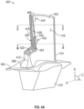
- FIGS. 4A-4C schematic illustrations of an airfoil 400 not falling within the scope of the claims are shown.
- FIG. 4A is an isometric illustration of the airfoil 400.
- FIG. 4B is a cross-sectional illustration of the airfoil 400 as viewed along the line B-B shown in FIG. 4A .
- FIG. 4C is a cross-sectional illustration of the airfoil 400 as viewed along the line C-C shown in FIG. 4A .
- the airfoil 400 is arranged as a blade having an airfoil body 402 that extends from a platform 404.
- the airfoil body 402 attaches to or is connected to the platform 404 at a root 406 (i.e., inner diameter) and extends radially outward to a tip 408 (i.e., outer diameter).
- the platform 404 may be integrally formed with or attached to an attachment element 410 and/or the airfoil body 402, the attachment element 410 being configured to attach to or engage with a rotor disc for installation of the airfoil 400 to the rotor disc.
- the airfoil body 402 extends in an axial direction A from a leading edge 412 to a trailing edge 414, and in a radial direction R from the root 406 to the tip 408. In the circumferential direction C, the airfoil body 402 extends between a pressure side 416 and a suction side 418.
- the airfoil body 402 defines a number of internal cooling cavities. As shown in FIGS. 4A-4C , a main body cavity 420 is arranged to cool portions of the airfoil body 402 aft of the leading edge 412, and may be a serpentine cavity. As shown, the main body cavity 420 extends to the trailing edge 414. At the leading edge 412 of the airfoil body 402, a leading edge cavity 422 is provided, which may include an impingement and film cooling arrangement, as will be appreciated by those of skill in the art.
- a cavity arrangement Forward of the main body cavity 420 and aft of the leading edge cavity 422 is a cavity arrangement that is configured to provide improved cooling to the airfoil body 402 toward the tip 408.
- a first shielding sidewall cavity 424, a second shielding sidewall cavity 426, and a shielded sidewall cavity 428 are arranged within the airfoil body 402.
- the first shielding sidewall cavity 424 is arranged adjacent an external wall of the airfoil body 402, in this case the pressure side 416, proximate the root 406.
- the second shielding sidewall cavity 426 is arranged adjacent an external wall of the airfoil body 402, in this case the suction side 418, proximate the root 406.
- the shielded sidewall cavity 428, proximate the root 406, is arranged within the airfoil body 402 between the first shielding sidewall cavity 424 and the second shielding sidewall cavity 426. That is, proximate the root, the shielded sidewall cavity 428 has no direct thermal contact with the exterior surfaces of the airfoil body 402. Thus, the shielded sidewall cavity 428, proximate the root 406, may not have substantial heat pick-up and air passing therethrough will remain relatively cool.
- the first shielding sidewall cavity 424 begins at the root 406 and extends radially outward toward the tip 408.
- the first shielding sidewall cavity 424 stops or is truncated at a dead end 430 and thus does not span the airfoil body 402 from the root 406 to the tip 408.
- the shielded sidewall cavity 428 transitions from being separated from the pressure side 416 to being proximate the pressure side 416 of the airfoil body 402 and extends along the pressure side from the dead end 430 to the tip 408.
- the second shielding sidewall cavity 426 in this embodiment, extends radially outward from the root 406 to the tip 408 along the suction side 418 of the airfoil body 402.
- the cross-sectional area of the shielded sidewall cavity 428 may change in area when transitioning from being shielded to being adjacent an external sidewall of the airfoil body 402.
- one or more first film holes 432 are arranged along the pressure side 416 and fluidly connect the first shielding sidewall cavity 424 to an exterior of the airfoil body 402.
- the first film holes 432 are arranged on the airfoil body 402 radially inward from the location of the dead end 430.
- One or more second film holes 434 are arranged along the pressure side 416 and fluidly connect the shielded sidewall cavity 428 to an exterior of the airfoil body 402.
- the second film holes 434 are arranged on the airfoil body 402 radially outward from the location of the dead end 430.
- FIGS. 4A-4C illustrate a particular airfoil cavity arrangement
- the truncated shielding sidewall cavity may be located on the suction side of the airfoil, and a full span shielding sidewall cavity may be located on the pressure side.
- the illustratively truncated cavity may not truncate, as described further below.
- one or more of the sidewall cavities (or portions thereof) can include one or more heat transfer augmentation features.
- Heat transfer augmentation features can include, but are not limited to, turbulators, trip strips (including, but not limited to normal, skewed, segmented skewed, chevron, segmented chevron, W-shaped, and discrete W's), pin fins, hemispherical bumps and/or dimples, as well as non-hemispherical shaped bumps and/or dimples, etc.
- the core assembly 550 may be used to form and manufacture airfoils.
- the core assembly 550 includes a main body cavity core 552, a leading edge cavity core 554, and a plurality of sidewall cavity cores 556, 558, 560. Although shown with a single or unitary main body cavity core 552, those of skill in the art will appreciate that the main body cavities may be formed by one or more cores having various arrangements and geometries.
- the formed airfoil, using the core assembly 550 of FIG. 5 may be substantially similar to the airfoil 400 shown in FIGS. 4A-4C .
- the sidewall cavity cores 556, 558, 560 are arranged between the main body cavity core 552 and the leading edge cavity core 554.
- a first sidewall cavity core 556 is arranged to form a cavity along a pressure side of a formed airfoil, such as shown and described above.
- the first sidewall cavity core 556 does not extend a full length of the formed airfoil, but rather ends at a core end 562 that is located at a radial position between a formed root and a formed tip of the formed airfoil.
- the first sidewall cavity core 556 forms a first shielding sidewall cavity in the formed airfoil, similar to that shown and described above.
- a second sidewall cavity core 558 is arranged as a full-length or full-span core that extends along a formed suction side and radially extends from a formed root to a formed tip of the airfoil.
- the second sidewall cavity core 558 forms a second shielding sidewall cavity in the formed airfoil, similar to that shown and described above.
- a third sidewall cavity core 560 is arranged as a full-length or full-span core that is arranged between the first and second sidewall cavity core 556, 558 at a root portion of the formed airfoil and then transitions to a sidewall position above the core end 562 of the first sidewall cavity core 556.
- FIG. 6 a schematic illustration of a core assembly 670 according to the present invention is shown.
- the core assembly 670 may be used to form and manufacture airfoils.
- the core assembly 670 includes a main body cavity core 672, a leading edge cavity core 674, and a plurality of sidewall cavity cores 676, 678, 680.
- main body cavity core 672 Although shown with a single or unitary main body cavity core 672, those of skill in the art will appreciate that the main body cavities may be formed by one or more cores having various arrangements and geometries.
- the sidewall cavity cores 676, 678, 680 are arranged between the main body cavity core 672 and the leading edge cavity core 674.
- a first sidewall cavity core 676 is arranged to form a cavity along a pressure side of a formed airfoil, such as shown and described above.
- the first sidewall cavity core 676 extends a full length of the formed airfoil, but shifts or transitions aftward along a sidewall of the formed airfoil and extends adjacent a portion of the main body cavity core 672.
- the first sidewall cavity core 676 shifts aftward at a transition portion 682.
- the first sidewall cavity core 676 forms a first shielding sidewall cavity in the formed airfoil.
- a second sidewall cavity core 678 is arranged as a full-length or full-span core that extends along a formed suction side and radially extends from a formed root to a formed tip of the airfoil.
- the second sidewall cavity core 678 forms a second shielding sidewall cavity in the formed airfoil, similar to that shown and described above.
- a third sidewall cavity core 680 is arranged as a full-length or full-span core that is arranged between the first and second sidewall cavity core 676, 678 at a root portion of the formed airfoil and then transitions to a sidewall position above the transition portion 682 of the first sidewall cavity core 556.
- the third sidewall cavity core 680 transitions toward a side wall of a formed airfoil radially outward from the transition portion 682 of first sidewall cavity core 676.
- the first sidewall cavity core 676 interferes with the structure of the main body cavity core 672. Accordingly, the geometry of the main body cavity core 672, and the cavities formed thereby, are adjusted to accommodate the geometry of the first sidewall cavity core 676 (and cavity formed thereby).
- the invention described herein incorporates radially flowing cores/cavities that are used to cool an inner diameter and middle portion of an airfoil, with a shielded core/cavity arranged to provide cooling at outer diameter portions of the airfoil.
- the shielded sidewall cavity will be able to cool the outer diameter portions of the airfoil efficiently because the cooling air therein has been shielded from heat transfer radially inward from the tip region.
- the invention provided herein can enable improved part life and thrust specific fuel consumption.
- the term "about” is intended to include the degree of error associated with measurement of the particular quantity based upon the equipment available at the time of filing the application. For example, “about” may include a range of ⁇ 8%, or 5%, or 2% of a given value or other percentage change as will be appreciated by those of skill in the art for the particular measurement and/or dimensions referred to herein.
- the terminology used herein is for the purpose of describing particular embodiments only and is not intended to be limiting of the present invention.
- the singular forms "a,” “an,” and “the” are intended to include the plural forms as well, unless the context clearly indicates otherwise.
Landscapes
- Engineering & Computer Science (AREA)
- Mechanical Engineering (AREA)
- General Engineering & Computer Science (AREA)
- Architecture (AREA)
- Physics & Mathematics (AREA)
- Fluid Mechanics (AREA)
- Turbine Rotor Nozzle Sealing (AREA)
Claims (11)
- Profil aérodynamique (400) pour un moteur à turbine à gaz (20), le profil aérodynamique comprenant :un corps de profil aérodynamique (402) s'étendant entre un bord d'attaque (412) et un bord de fuite (414) dans une direction axiale, entre un côté pression (416) et un côté aspiration (418) dans une direction circonférentielle, et entre un pied (406) et une pointe (408) dans une direction radiale ;une première cavité de paroi latérale de protection (424) située à proximité du côté pression et du côté aspiration à proximité de la racine du corps de profil aérodynamique et s'étendant radialement vers la pointe ;une seconde cavité de paroi latérale de protection (426) située à proximité de l'autre côté pression et côté aspiration à proximité de la racine du corps de profil aérodynamique et s'étendant radialement vers la pointe ;une cavité de paroi latérale protégée (428) située entre la première cavité de paroi latérale de protection et la seconde cavité de paroi latérale de protection à proximité de la racine ; etune cavité de corps principal (420) située à l'arrière de la première cavité de paroi latérale de protection, de la seconde cavité de paroi latérale de protection et de la cavité de paroi latérale protégée, dans lequel la cavité de corps principal s'étendant jusqu'au bord de fuite du corps de profil aérodynamique,dans lequel la première cavité de paroi latérale de protection (424) fait une transition vers l'arrière au niveau d'une partie de transition et s'étend de la racine à la pointe, etdans lequel la cavité de paroi latérale protégée (428) n'est adjacente ni au côté pression ni au côté aspiration à proximité de la racine de sorte que la cavité de paroi latérale protégée n'a pas de contact thermique direct avec les surfaces extérieures du corps de profil aérodynamique parce que la cavité de paroi latérale protégée (428) est entre la première cavité de paroi latérale de protection (424) et la seconde cavité de paroi latérale de protection (426), et la cavité de paroi latérale protégée (428) fait une transition vers le côté pression ou le côté aspiration radialement vers l'extérieur à partir de la partie de transition pour être à proximité d'au moins l'un parmi les côtés pression et le côté aspiration à proximité de la pointe de sorte que la cavité de paroi latérale protégée (428) assure le refroidissement des parties du diamètre extérieur du profil aérodynamique.
- Profil aérodynamique selon la revendication 1, dans lequel la première cavité de paroi latérale de protection (424) est positionnée le long du côté pression et la seconde cavité de paroi latérale de protection (426) est positionnée le long du côté aspiration du corps du profil aérodynamique.
- Profil aérodynamique selon la revendication 1 ou 2, dans lequel la seconde cavité de paroi latérale de protection (426) s'étend de la racine jusqu'à la pointe du corps du profil aérodynamique.
- Profil aérodynamique selon une quelconque revendication précédente, comprenant un ou plusieurs premiers trous de film (432) reliant fluidiquement la première cavité de paroi latérale de protection (424) à un extérieur du corps de profil aérodynamique et un ou plusieurs seconds trous de film (434) reliant fluidiquement cavité de paroi latérale de protection (428) vers l'extérieur du corps de profil aérodynamique.
- Profil aérodynamique selon une quelconque revendication précédente, dans lequel la cavité du corps principal (420) est une cavité en serpentin, et dans lequel la première cavité de paroi latérale de protection (424) effectue une transition pour protéger une partie de la cavité du corps principal à proximité de la pointe.
- Profil aérodynamique selon une quelconque revendication précédente, comprenant une cavité de bord d'attaque (422) en avant de la première cavité de paroi latérale de protection (424) et à proximité du bord d'attaque du corps de profil aérodynamique.
- Ensemble noyau (670) pour former un profil aérodynamique selon une quelconque revendication précédente, l'ensemble noyau comprenant :un premier noyau de cavité de paroi latérale (676) agencé pour former la première cavité de paroi latérale de protection (424) du profil aérodynamique formé, le premier noyau de cavité de paroi latérale étant positionné pour être adjacent à un côté aspiration ou à un côté pression du profil aérodynamique formé au niveau d'une racine du profil aérodynamique formé ;un deuxième noyau de cavité de paroi latérale (678) agencé pour former la seconde cavité de paroi latérale de protection (426) du profil aérodynamique formé, le deuxième noyau de cavité de paroi latérale étant positionné pour être adjacent à l'autre du côté aspiration et du côté pression du profil aérodynamique formé au niveau de la racine du profil aérodynamique formé ;un troisième noyau de cavité de paroi latérale (680) agencé pour former la cavité de paroi latérale protégée (428) du profil aérodynamique formé, le troisième noyau de cavité de paroi latérale étant positionné entre le premier noyau de cavité de paroi latérale (676) et le deuxième noyau de cavité de paroi latérale (678) au niveau d'une racine du profil aérodynamique formé et des transitions pour être à proximité d'au moins l'un parmi le côté pression et le côté aspiration à proximité d'une pointe du profil aérodynamique formé ; etun noyau de cavité de corps principal (672) situé à l'arrière du premier noyau de cavité de paroi latérale, du deuxième noyau de cavité de paroi latérale et du troisième noyau de cavité de paroi latérale, dans lequel le noyau de cavité de corps principal s'étend jusqu'à un bord de fuite du corps de profil aérodynamique formé, etdans lequel la cavité de paroi latérale protégée formée (428) n'est adjacente ni au côté pression ni au côté aspiration à proximité de la racine, de sorte que la cavité de paroi latérale protégée formée n'a pas de contact thermique direct avec les surfaces extérieures du corps de profil aérodynamique formé, et les transitions doivent être à proximité d'au moins l'un du côté pression et du côté aspiration à proximité de la pointe, de sorte que la cavité de paroi latérale protégée formée assure le refroidissement des parties de diamètre extérieur du profil aérodynamique formé, et dans lequel le premier noyau de cavité de paroi latérale (676) effectue une transition vers l'arrière le long d'une partie de transition (682) et s'étend depuis la racine formée jusqu'à la pointe formée du profil aérodynamique formé.
- Ensemble de noyau selon la revendication 7, dans lequel le premier noyau de cavité de paroi latérale (676) est positionné le long du côté pression formé et le deuxième noyau de cavité de paroi latérale (678) est positionné le long du côté aspiration formé.
- Ensemble de noyau selon l'une quelconque des revendications 7 à 8, dans lequel le noyau de cavité du corps principal (672) définit un trajet d'écoulement en serpentin dans le profil aérodynamique formé, et dans lequel le premier noyau de cavité de paroi latérale (676) effectue une transition pour protéger une partie du noyau de cavité de corps principal à proximité de la pointe formée.
- Ensemble de noyau selon l'une quelconque des revendications 7 à 9, comprenant en outre un noyau de cavité de bord d'attaque (674) en avant du premier noyau de cavité de paroi latérale (676) et à proximité d'un bord d'attaque du profil aérodynamique formé.
- Moteur à turbine à gaz (20) comprenant :
une section de turbine (28) ayant une pluralité de profils aérodynamiques, dans lequel au moins un profil aérodynamique comprend le profil aérodynamique selon l'une quelconque des revendications 1 à 6.
Applications Claiming Priority (1)
| Application Number | Priority Date | Filing Date | Title |
|---|---|---|---|
| US15/968,865 US10753210B2 (en) | 2018-05-02 | 2018-05-02 | Airfoil having improved cooling scheme |
Publications (2)
| Publication Number | Publication Date |
|---|---|
| EP3564486A1 EP3564486A1 (fr) | 2019-11-06 |
| EP3564486B1 true EP3564486B1 (fr) | 2024-07-31 |
Family
ID=66286195
Family Applications (1)
| Application Number | Title | Priority Date | Filing Date |
|---|---|---|---|
| EP19171050.8A Active EP3564486B1 (fr) | 2018-05-02 | 2019-04-25 | Profil aérodynamique ayant un schéma de refroidissement amélioré |
Country Status (2)
| Country | Link |
|---|---|
| US (1) | US10753210B2 (fr) |
| EP (1) | EP3564486B1 (fr) |
Families Citing this family (1)
| Publication number | Priority date | Publication date | Assignee | Title |
|---|---|---|---|---|
| US11885230B2 (en) * | 2021-03-16 | 2024-01-30 | Doosan Heavy Industries & Construction Co. Ltd. | Airfoil with internal crossover passages and pin array |
Family Cites Families (111)
| Publication number | Priority date | Publication date | Assignee | Title |
|---|---|---|---|---|
| NL88170C (fr) * | 1952-10-31 | 1900-01-01 | ||
| US2879028A (en) * | 1954-03-31 | 1959-03-24 | Edward A Stalker | Cooled turbine blades |
| US3017159A (en) * | 1956-11-23 | 1962-01-16 | Curtiss Wright Corp | Hollow blade construction |
| US3191908A (en) * | 1961-05-02 | 1965-06-29 | Rolls Royce | Blades for fluid flow machines |
| US3275294A (en) * | 1963-11-14 | 1966-09-27 | Westinghouse Electric Corp | Elastic fluid apparatus |
| US3540810A (en) * | 1966-03-17 | 1970-11-17 | Gen Electric | Slanted partition for hollow airfoil vane insert |
| US3844678A (en) * | 1967-11-17 | 1974-10-29 | Gen Electric | Cooled high strength turbine bucket |
| US3574481A (en) * | 1968-05-09 | 1971-04-13 | James A Pyne Jr | Variable area cooled airfoil construction for gas turbines |
| US3736071A (en) * | 1970-11-27 | 1973-05-29 | Gen Electric | Bucket tip/collection slot combination for open-circuit liquid-cooled gas turbines |
| US3856433A (en) * | 1973-08-02 | 1974-12-24 | Gen Electric | Liquid cooled turbine bucket with dovetailed attachment |
| US4153386A (en) * | 1974-12-11 | 1979-05-08 | United Technologies Corporation | Air cooled turbine vanes |
| US4017210A (en) * | 1976-02-19 | 1977-04-12 | General Electric Company | Liquid-cooled turbine bucket with integral distribution and metering system |
| US4111604A (en) * | 1976-07-12 | 1978-09-05 | General Electric Company | Bucket tip construction for open circuit liquid cooled turbines |
| US4236870A (en) * | 1977-12-27 | 1980-12-02 | United Technologies Corporation | Turbine blade |
| US4218178A (en) * | 1978-03-31 | 1980-08-19 | General Motors Corporation | Turbine vane structure |
| US4314442A (en) * | 1978-10-26 | 1982-02-09 | Rice Ivan G | Steam-cooled blading with steam thermal barrier for reheat gas turbine combined with steam turbine |
| US4297077A (en) * | 1979-07-09 | 1981-10-27 | Westinghouse Electric Corp. | Cooled turbine vane |
| GB2163219B (en) * | 1981-10-31 | 1986-08-13 | Rolls Royce | Cooled turbine blade |
| GB2121483B (en) * | 1982-06-08 | 1985-02-13 | Rolls Royce | Cooled turbine blade for a gas turbine engine |
| US4487550A (en) * | 1983-01-27 | 1984-12-11 | The United States Of America As Represented By The Secretary Of The Air Force | Cooled turbine blade tip closure |
| US4770608A (en) * | 1985-12-23 | 1988-09-13 | United Technologies Corporation | Film cooled vanes and turbines |
| US5012853A (en) * | 1988-09-20 | 1991-05-07 | Sundstrand Corporation | Process for making articles with smooth complex internal geometries |
| US5405242A (en) * | 1990-07-09 | 1995-04-11 | United Technologies Corporation | Cooled vane |
| FR2678318B1 (fr) * | 1991-06-25 | 1993-09-10 | Snecma | Aube refroidie de distributeur de turbine. |
| US5243759A (en) * | 1991-10-07 | 1993-09-14 | United Technologies Corporation | Method of casting to control the cooling air flow rate of the airfoil trailing edge |
| FR2689176B1 (fr) * | 1992-03-25 | 1995-07-13 | Snecma | Aube refrigeree de turbo-machine. |
| US5660524A (en) * | 1992-07-13 | 1997-08-26 | General Electric Company | Airfoil blade having a serpentine cooling circuit and impingement cooling |
| US5387085A (en) * | 1994-01-07 | 1995-02-07 | General Electric Company | Turbine blade composite cooling circuit |
| US5484258A (en) * | 1994-03-01 | 1996-01-16 | General Electric Company | Turbine airfoil with convectively cooled double shell outer wall |
| US5378108A (en) * | 1994-03-25 | 1995-01-03 | United Technologies Corporation | Cooled turbine blade |
| US5603606A (en) * | 1994-11-14 | 1997-02-18 | Solar Turbines Incorporated | Turbine cooling system |
| US5702232A (en) * | 1994-12-13 | 1997-12-30 | United Technologies Corporation | Cooled airfoils for a gas turbine engine |
| US5820337A (en) * | 1995-01-03 | 1998-10-13 | General Electric Company | Double wall turbine parts |
| US5813836A (en) * | 1996-12-24 | 1998-09-29 | General Electric Company | Turbine blade |
| US6287075B1 (en) * | 1997-10-22 | 2001-09-11 | General Electric Company | Spanwise fan diffusion hole airfoil |
| FR2782118B1 (fr) * | 1998-08-05 | 2000-09-15 | Snecma | Aube de turbine refroidie a bord de fuite amenage |
| US6126397A (en) * | 1998-12-22 | 2000-10-03 | United Technologies Corporation | Trailing edge cooling apparatus for a gas turbine airfoil |
| US6206638B1 (en) * | 1999-02-12 | 2001-03-27 | General Electric Company | Low cost airfoil cooling circuit with sidewall impingement cooling chambers |
| US6174135B1 (en) * | 1999-06-30 | 2001-01-16 | General Electric Company | Turbine blade trailing edge cooling openings and slots |
| DE19939179B4 (de) * | 1999-08-20 | 2007-08-02 | Alstom | Kühlbare Schaufel für eine Gasturbine |
| US6290463B1 (en) * | 1999-09-30 | 2001-09-18 | General Electric Company | Slotted impingement cooling of airfoil leading edge |
| US6254334B1 (en) * | 1999-10-05 | 2001-07-03 | United Technologies Corporation | Method and apparatus for cooling a wall within a gas turbine engine |
| DE19963349A1 (de) * | 1999-12-27 | 2001-06-28 | Abb Alstom Power Ch Ag | Schaufel für Gasturbinen mit Drosselquerschnitt an Hinterkante |
| US6616406B2 (en) * | 2001-06-11 | 2003-09-09 | Alstom (Switzerland) Ltd | Airfoil trailing edge cooling construction |
| GB0114503D0 (en) * | 2001-06-14 | 2001-08-08 | Rolls Royce Plc | Air cooled aerofoil |
| US6551062B2 (en) * | 2001-08-30 | 2003-04-22 | General Electric Company | Turbine airfoil for gas turbine engine |
| US6558122B1 (en) * | 2001-11-14 | 2003-05-06 | General Electric Company | Second-stage turbine bucket airfoil |
| US6974308B2 (en) * | 2001-11-14 | 2005-12-13 | Honeywell International, Inc. | High effectiveness cooled turbine vane or blade |
| US6607356B2 (en) * | 2002-01-11 | 2003-08-19 | General Electric Company | Crossover cooled airfoil trailing edge |
| US6779977B2 (en) * | 2002-12-17 | 2004-08-24 | General Electric Company | Airfoil shape for a turbine bucket |
| US6981846B2 (en) * | 2003-03-12 | 2006-01-03 | Florida Turbine Technologies, Inc. | Vortex cooling of turbine blades |
| US20050006047A1 (en) * | 2003-07-10 | 2005-01-13 | General Electric Company | Investment casting method and cores and dies used therein |
| US7104757B2 (en) * | 2003-07-29 | 2006-09-12 | Siemens Aktiengesellschaft | Cooled turbine blade |
| US6981840B2 (en) * | 2003-10-24 | 2006-01-03 | General Electric Company | Converging pin cooled airfoil |
| US6984103B2 (en) * | 2003-11-20 | 2006-01-10 | General Electric Company | Triple circuit turbine blade |
| US7118326B2 (en) * | 2004-06-17 | 2006-10-10 | Siemens Power Generation, Inc. | Cooled gas turbine vane |
| US7448433B2 (en) * | 2004-09-24 | 2008-11-11 | Honeywell International Inc. | Rapid prototype casting |
| US7478994B2 (en) * | 2004-11-23 | 2009-01-20 | United Technologies Corporation | Airfoil with supplemental cooling channel adjacent leading edge |
| US7156619B2 (en) * | 2004-12-21 | 2007-01-02 | Pratt & Whitney Canada Corp. | Internally cooled gas turbine airfoil and method |
| US7334991B2 (en) * | 2005-01-07 | 2008-02-26 | Siemens Power Generation, Inc. | Turbine blade tip cooling system |
| US20070201980A1 (en) * | 2005-10-11 | 2007-08-30 | Honeywell International, Inc. | Method to augment heat transfer using chamfered cylindrical depressions in cast internal cooling passages |
| US7744347B2 (en) * | 2005-11-08 | 2010-06-29 | United Technologies Corporation | Peripheral microcircuit serpentine cooling for turbine airfoils |
| US7364405B2 (en) * | 2005-11-23 | 2008-04-29 | United Technologies Corporation | Microcircuit cooling for vanes |
| US7303376B2 (en) * | 2005-12-02 | 2007-12-04 | Siemens Power Generation, Inc. | Turbine airfoil with outer wall cooling system and inner mid-chord hot gas receiving cavity |
| US7293961B2 (en) * | 2005-12-05 | 2007-11-13 | General Electric Company | Zigzag cooled turbine airfoil |
| EP1847684A1 (fr) * | 2006-04-21 | 2007-10-24 | Siemens Aktiengesellschaft | Aube de turbine |
| US7607890B2 (en) * | 2006-06-07 | 2009-10-27 | United Technologies Corporation | Robust microcircuits for turbine airfoils |
| US20080028606A1 (en) * | 2006-07-26 | 2008-02-07 | General Electric Company | Low stress turbins bucket |
| US7780413B2 (en) * | 2006-08-01 | 2010-08-24 | Siemens Energy, Inc. | Turbine airfoil with near wall inflow chambers |
| US7690894B1 (en) * | 2006-09-25 | 2010-04-06 | Florida Turbine Technologies, Inc. | Ceramic core assembly for serpentine flow circuit in a turbine blade |
| US7556476B1 (en) * | 2006-11-16 | 2009-07-07 | Florida Turbine Technologies, Inc. | Turbine airfoil with multiple near wall compartment cooling |
| US7674093B2 (en) * | 2006-12-19 | 2010-03-09 | General Electric Company | Cluster bridged casting core |
| US7845906B2 (en) * | 2007-01-24 | 2010-12-07 | United Technologies Corporation | Dual cut-back trailing edge for airfoils |
| US7871246B2 (en) * | 2007-02-15 | 2011-01-18 | Siemens Energy, Inc. | Airfoil for a gas turbine |
| US7775768B2 (en) | 2007-03-06 | 2010-08-17 | United Technologies Corporation | Turbine component with axially spaced radially flowing microcircuit cooling channels |
| US7762775B1 (en) * | 2007-05-31 | 2010-07-27 | Florida Turbine Technologies, Inc. | Turbine airfoil with cooled thin trailing edge |
| US9163518B2 (en) * | 2008-03-18 | 2015-10-20 | United Technologies Corporation | Full coverage trailing edge microcircuit with alternating converging exits |
| US8105033B2 (en) * | 2008-06-05 | 2012-01-31 | United Technologies Corporation | Particle resistant in-wall cooling passage inlet |
| US8109735B2 (en) * | 2008-11-13 | 2012-02-07 | Honeywell International Inc. | Cooled component with a featured surface and related manufacturing method |
| US8137068B2 (en) * | 2008-11-21 | 2012-03-20 | United Technologies Corporation | Castings, casting cores, and methods |
| US8113780B2 (en) * | 2008-11-21 | 2012-02-14 | United Technologies Corporation | Castings, casting cores, and methods |
| US8231329B2 (en) * | 2008-12-30 | 2012-07-31 | General Electric Company | Turbine blade cooling with a hollow airfoil configured to minimize a distance between a pin array section and the trailing edge of the air foil |
| US8721285B2 (en) * | 2009-03-04 | 2014-05-13 | Siemens Energy, Inc. | Turbine blade with incremental serpentine cooling channels beneath a thermal skin |
| US9528382B2 (en) * | 2009-11-10 | 2016-12-27 | General Electric Company | Airfoil heat shield |
| US8511994B2 (en) * | 2009-11-23 | 2013-08-20 | United Technologies Corporation | Serpentine cored airfoil with body microcircuits |
| EP2547871B1 (fr) * | 2010-03-19 | 2020-04-29 | Ansaldo Energia IP UK Limited | Profil de turbine à gaz avec trous d'éjection de réfrigérant sur le bord de fuite |
| US8449254B2 (en) | 2010-03-29 | 2013-05-28 | United Technologies Corporation | Branched airfoil core cooling arrangement |
| US9121290B2 (en) * | 2010-05-06 | 2015-09-01 | United Technologies Corporation | Turbine airfoil with body microcircuits terminating in platform |
| EP2564028B1 (fr) * | 2010-06-23 | 2015-07-29 | Siemens Aktiengesellschaft | Aube de turbine a gaz |
| EP2426317A1 (fr) * | 2010-09-03 | 2012-03-07 | Siemens Aktiengesellschaft | Aube de turbine pour une turbine à gaz |
| US8753083B2 (en) * | 2011-01-14 | 2014-06-17 | General Electric Company | Curved cooling passages for a turbine component |
| US9017025B2 (en) * | 2011-04-22 | 2015-04-28 | Siemens Energy, Inc. | Serpentine cooling circuit with T-shaped partitions in a turbine airfoil |
| EP2628901A1 (fr) * | 2012-02-15 | 2013-08-21 | Siemens Aktiengesellschaft | Aube de turbine à gaz avec refroidissement par impact |
| US8414263B1 (en) | 2012-03-22 | 2013-04-09 | Florida Turbine Technologies, Inc. | Turbine stator vane with near wall integrated micro cooling channels |
| US8985940B2 (en) * | 2012-03-30 | 2015-03-24 | Solar Turbines Incorporated | Turbine cooling apparatus |
| US9296039B2 (en) * | 2012-04-24 | 2016-03-29 | United Technologies Corporation | Gas turbine engine airfoil impingement cooling |
| US9422817B2 (en) | 2012-05-31 | 2016-08-23 | United Technologies Corporation | Turbine blade root with microcircuit cooling passages |
| US9115590B2 (en) | 2012-09-26 | 2015-08-25 | United Technologies Corporation | Gas turbine engine airfoil cooling circuit |
| US8951004B2 (en) * | 2012-10-23 | 2015-02-10 | Siemens Aktiengesellschaft | Cooling arrangement for a gas turbine component |
| US8985949B2 (en) * | 2013-04-29 | 2015-03-24 | Siemens Aktiengesellschaft | Cooling system including wavy cooling chamber in a trailing edge portion of an airfoil assembly |
| US9528380B2 (en) | 2013-12-18 | 2016-12-27 | General Electric Company | Turbine bucket and method for cooling a turbine bucket of a gas turbine engine |
| US10329923B2 (en) | 2014-03-10 | 2019-06-25 | United Technologies Corporation | Gas turbine engine airfoil leading edge cooling |
| FR3021699B1 (fr) | 2014-05-28 | 2019-08-16 | Safran Aircraft Engines | Aube de turbine a refroidissement optimise au niveau de son bord de fuite |
| US9765699B2 (en) * | 2014-12-30 | 2017-09-19 | General Electric Company | Gas turbine sealing |
| US20170002662A1 (en) | 2015-07-01 | 2017-01-05 | United Technologies Corporation | Gas turbine engine airfoil with bi-axial skin core |
| GB201512810D0 (en) * | 2015-07-21 | 2015-09-02 | Rolls Royce Plc | Thermal shielding in a gas turbine |
| FR3041989B1 (fr) | 2015-10-06 | 2020-04-17 | Safran Aircraft Engines | Aube comportant un bord de fuite comprenant trois regions de refroidissement distinctes |
| US10053989B2 (en) * | 2015-12-21 | 2018-08-21 | General Electric Company | Cooling circuit for a multi-wall blade |
| US10119405B2 (en) | 2015-12-21 | 2018-11-06 | General Electric Company | Cooling circuit for a multi-wall blade |
| FR3056631B1 (fr) | 2016-09-29 | 2018-10-19 | Safran | Circuit de refroidissement ameliore pour aubes |
| US10815800B2 (en) * | 2016-12-05 | 2020-10-27 | Raytheon Technologies Corporation | Radially diffused tip flag |
-
2018
- 2018-05-02 US US15/968,865 patent/US10753210B2/en active Active
-
2019
- 2019-04-25 EP EP19171050.8A patent/EP3564486B1/fr active Active
Also Published As
| Publication number | Publication date |
|---|---|
| US20190338652A1 (en) | 2019-11-07 |
| EP3564486A1 (fr) | 2019-11-06 |
| US10753210B2 (en) | 2020-08-25 |
Similar Documents
| Publication | Publication Date | Title |
|---|---|---|
| EP3399145B1 (fr) | Profil d'aube avec cavité hybride de bord d'attaque | |
| US11649731B2 (en) | Airfoil having internal hybrid cooling cavities | |
| EP3502420B1 (fr) | Composant de moteur à turbine à gaz et moteur à turbine à gaz associé | |
| EP3567218B1 (fr) | Profil aérodynamique présentant un schéma amélioré de refroidissement de bord d'attaque et une meilleure résistance aux dommages | |
| EP3567219B1 (fr) | Profil aérodynamique pour moteur à turbine à gaz | |
| EP3564485B1 (fr) | Surfaces portantes, noyaux et procédés de fabrication pour former des surfaces portantes comprenant des circuits de refroidissement de plate-formes reliées de manière fluidique | |
| EP3564486B1 (fr) | Profil aérodynamique ayant un schéma de refroidissement amélioré | |
| EP3467264B1 (fr) | Aube pour un moteur à turbine à gaz et structure de noyau pour la fabrication d'une aube, associée | |
| EP3693546B1 (fr) | Profil aérodynamique comportant une cavité fermée d'extrémité et agencement de noyau associé | |
| EP3467265B1 (fr) | Aube pour un moteur à turbine à gaz et structure de noyau pour la fabrication d'une aube, associée | |
| US10626733B2 (en) | Airfoil having internal hybrid cooling cavities | |
| US10633980B2 (en) | Airfoil having internal hybrid cooling cavities | |
| EP3613949B1 (fr) | Profil aérodynamique présentant un schéma de refroidissement par flux amélioré et une meilleure résistance aux dommages | |
| EP3550110B1 (fr) | Profil aérodynamique ayant un schéma de refroidissement de bord d'attaque à compensation de frappe arrière |
Legal Events
| Date | Code | Title | Description |
|---|---|---|---|
| PUAI | Public reference made under article 153(3) epc to a published international application that has entered the european phase |
Free format text: ORIGINAL CODE: 0009012 |
|
| STAA | Information on the status of an ep patent application or granted ep patent |
Free format text: STATUS: THE APPLICATION HAS BEEN PUBLISHED |
|
| AK | Designated contracting states |
Kind code of ref document: A1 Designated state(s): AL AT BE BG CH CY CZ DE DK EE ES FI FR GB GR HR HU IE IS IT LI LT LU LV MC MK MT NL NO PL PT RO RS SE SI SK SM TR |
|
| AX | Request for extension of the european patent |
Extension state: BA ME |
|
| STAA | Information on the status of an ep patent application or granted ep patent |
Free format text: STATUS: REQUEST FOR EXAMINATION WAS MADE |
|
| 17P | Request for examination filed |
Effective date: 20200429 |
|
| RBV | Designated contracting states (corrected) |
Designated state(s): AL AT BE BG CH CY CZ DE DK EE ES FI FR GB GR HR HU IE IS IT LI LT LU LV MC MK MT NL NO PL PT RO RS SE SI SK SM TR |
|
| RAP1 | Party data changed (applicant data changed or rights of an application transferred) |
Owner name: RAYTHEON TECHNOLOGIES CORPORATION |
|
| STAA | Information on the status of an ep patent application or granted ep patent |
Free format text: STATUS: EXAMINATION IS IN PROGRESS |
|
| 17Q | First examination report despatched |
Effective date: 20220621 |
|
| RAP3 | Party data changed (applicant data changed or rights of an application transferred) |
Owner name: RTX CORPORATION |
|
| GRAP | Despatch of communication of intention to grant a patent |
Free format text: ORIGINAL CODE: EPIDOSNIGR1 |
|
| STAA | Information on the status of an ep patent application or granted ep patent |
Free format text: STATUS: GRANT OF PATENT IS INTENDED |
|
| INTG | Intention to grant announced |
Effective date: 20240209 |
|
| GRAS | Grant fee paid |
Free format text: ORIGINAL CODE: EPIDOSNIGR3 |
|
| GRAA | (expected) grant |
Free format text: ORIGINAL CODE: 0009210 |
|
| STAA | Information on the status of an ep patent application or granted ep patent |
Free format text: STATUS: THE PATENT HAS BEEN GRANTED |
|
| AK | Designated contracting states |
Kind code of ref document: B1 Designated state(s): AL AT BE BG CH CY CZ DE DK EE ES FI FR GB GR HR HU IE IS IT LI LT LU LV MC MK MT NL NO PL PT RO RS SE SI SK SM TR |
|
| REG | Reference to a national code |
Ref country code: CH Ref legal event code: EP Ref country code: GB Ref legal event code: FG4D |
|
| REG | Reference to a national code |
Ref country code: DE Ref legal event code: R096 Ref document number: 602019055996 Country of ref document: DE |
|
| REG | Reference to a national code |
Ref country code: IE Ref legal event code: FG4D |
|
| REG | Reference to a national code |
Ref country code: LT Ref legal event code: MG9D |
|
| REG | Reference to a national code |
Ref country code: NL Ref legal event code: MP Effective date: 20240731 |
|
| PG25 | Lapsed in a contracting state [announced via postgrant information from national office to epo] |
Ref country code: PT Free format text: LAPSE BECAUSE OF FAILURE TO SUBMIT A TRANSLATION OF THE DESCRIPTION OR TO PAY THE FEE WITHIN THE PRESCRIBED TIME-LIMIT Effective date: 20241202 |
|
| REG | Reference to a national code |
Ref country code: AT Ref legal event code: MK05 Ref document number: 1708636 Country of ref document: AT Kind code of ref document: T Effective date: 20240731 |
|
| PG25 | Lapsed in a contracting state [announced via postgrant information from national office to epo] |
Ref country code: PT Free format text: LAPSE BECAUSE OF FAILURE TO SUBMIT A TRANSLATION OF THE DESCRIPTION OR TO PAY THE FEE WITHIN THE PRESCRIBED TIME-LIMIT Effective date: 20241202 |
|
| PG25 | Lapsed in a contracting state [announced via postgrant information from national office to epo] |
Ref country code: NO Free format text: LAPSE BECAUSE OF FAILURE TO SUBMIT A TRANSLATION OF THE DESCRIPTION OR TO PAY THE FEE WITHIN THE PRESCRIBED TIME-LIMIT Effective date: 20241031 |
|
| PG25 | Lapsed in a contracting state [announced via postgrant information from national office to epo] |
Ref country code: NL Free format text: LAPSE BECAUSE OF FAILURE TO SUBMIT A TRANSLATION OF THE DESCRIPTION OR TO PAY THE FEE WITHIN THE PRESCRIBED TIME-LIMIT Effective date: 20240731 Ref country code: FI Free format text: LAPSE BECAUSE OF FAILURE TO SUBMIT A TRANSLATION OF THE DESCRIPTION OR TO PAY THE FEE WITHIN THE PRESCRIBED TIME-LIMIT Effective date: 20240731 Ref country code: GR Free format text: LAPSE BECAUSE OF FAILURE TO SUBMIT A TRANSLATION OF THE DESCRIPTION OR TO PAY THE FEE WITHIN THE PRESCRIBED TIME-LIMIT Effective date: 20241101 Ref country code: PL Free format text: LAPSE BECAUSE OF FAILURE TO SUBMIT A TRANSLATION OF THE DESCRIPTION OR TO PAY THE FEE WITHIN THE PRESCRIBED TIME-LIMIT Effective date: 20240731 |
|
| PG25 | Lapsed in a contracting state [announced via postgrant information from national office to epo] |
Ref country code: BG Free format text: LAPSE BECAUSE OF FAILURE TO SUBMIT A TRANSLATION OF THE DESCRIPTION OR TO PAY THE FEE WITHIN THE PRESCRIBED TIME-LIMIT Effective date: 20240731 |
|
| PG25 | Lapsed in a contracting state [announced via postgrant information from national office to epo] |
Ref country code: LV Free format text: LAPSE BECAUSE OF FAILURE TO SUBMIT A TRANSLATION OF THE DESCRIPTION OR TO PAY THE FEE WITHIN THE PRESCRIBED TIME-LIMIT Effective date: 20240731 |
|
| PG25 | Lapsed in a contracting state [announced via postgrant information from national office to epo] |
Ref country code: IS Free format text: LAPSE BECAUSE OF FAILURE TO SUBMIT A TRANSLATION OF THE DESCRIPTION OR TO PAY THE FEE WITHIN THE PRESCRIBED TIME-LIMIT Effective date: 20241130 Ref country code: AT Free format text: LAPSE BECAUSE OF FAILURE TO SUBMIT A TRANSLATION OF THE DESCRIPTION OR TO PAY THE FEE WITHIN THE PRESCRIBED TIME-LIMIT Effective date: 20240731 |
|
| PG25 | Lapsed in a contracting state [announced via postgrant information from national office to epo] |
Ref country code: HR Free format text: LAPSE BECAUSE OF FAILURE TO SUBMIT A TRANSLATION OF THE DESCRIPTION OR TO PAY THE FEE WITHIN THE PRESCRIBED TIME-LIMIT Effective date: 20240731 |
|
| PG25 | Lapsed in a contracting state [announced via postgrant information from national office to epo] |
Ref country code: ES Free format text: LAPSE BECAUSE OF FAILURE TO SUBMIT A TRANSLATION OF THE DESCRIPTION OR TO PAY THE FEE WITHIN THE PRESCRIBED TIME-LIMIT Effective date: 20240731 Ref country code: RS Free format text: LAPSE BECAUSE OF FAILURE TO SUBMIT A TRANSLATION OF THE DESCRIPTION OR TO PAY THE FEE WITHIN THE PRESCRIBED TIME-LIMIT Effective date: 20241031 |
|
| PG25 | Lapsed in a contracting state [announced via postgrant information from national office to epo] |
Ref country code: RS Free format text: LAPSE BECAUSE OF FAILURE TO SUBMIT A TRANSLATION OF THE DESCRIPTION OR TO PAY THE FEE WITHIN THE PRESCRIBED TIME-LIMIT Effective date: 20241031 Ref country code: PL Free format text: LAPSE BECAUSE OF FAILURE TO SUBMIT A TRANSLATION OF THE DESCRIPTION OR TO PAY THE FEE WITHIN THE PRESCRIBED TIME-LIMIT Effective date: 20240731 Ref country code: NO Free format text: LAPSE BECAUSE OF FAILURE TO SUBMIT A TRANSLATION OF THE DESCRIPTION OR TO PAY THE FEE WITHIN THE PRESCRIBED TIME-LIMIT Effective date: 20241031 Ref country code: NL Free format text: LAPSE BECAUSE OF FAILURE TO SUBMIT A TRANSLATION OF THE DESCRIPTION OR TO PAY THE FEE WITHIN THE PRESCRIBED TIME-LIMIT Effective date: 20240731 Ref country code: LV Free format text: LAPSE BECAUSE OF FAILURE TO SUBMIT A TRANSLATION OF THE DESCRIPTION OR TO PAY THE FEE WITHIN THE PRESCRIBED TIME-LIMIT Effective date: 20240731 Ref country code: IS Free format text: LAPSE BECAUSE OF FAILURE TO SUBMIT A TRANSLATION OF THE DESCRIPTION OR TO PAY THE FEE WITHIN THE PRESCRIBED TIME-LIMIT Effective date: 20241130 Ref country code: HR Free format text: LAPSE BECAUSE OF FAILURE TO SUBMIT A TRANSLATION OF THE DESCRIPTION OR TO PAY THE FEE WITHIN THE PRESCRIBED TIME-LIMIT Effective date: 20240731 Ref country code: GR Free format text: LAPSE BECAUSE OF FAILURE TO SUBMIT A TRANSLATION OF THE DESCRIPTION OR TO PAY THE FEE WITHIN THE PRESCRIBED TIME-LIMIT Effective date: 20241101 Ref country code: FI Free format text: LAPSE BECAUSE OF FAILURE TO SUBMIT A TRANSLATION OF THE DESCRIPTION OR TO PAY THE FEE WITHIN THE PRESCRIBED TIME-LIMIT Effective date: 20240731 Ref country code: ES Free format text: LAPSE BECAUSE OF FAILURE TO SUBMIT A TRANSLATION OF THE DESCRIPTION OR TO PAY THE FEE WITHIN THE PRESCRIBED TIME-LIMIT Effective date: 20240731 Ref country code: BG Free format text: LAPSE BECAUSE OF FAILURE TO SUBMIT A TRANSLATION OF THE DESCRIPTION OR TO PAY THE FEE WITHIN THE PRESCRIBED TIME-LIMIT Effective date: 20240731 Ref country code: AT Free format text: LAPSE BECAUSE OF FAILURE TO SUBMIT A TRANSLATION OF THE DESCRIPTION OR TO PAY THE FEE WITHIN THE PRESCRIBED TIME-LIMIT Effective date: 20240731 |
|
| PG25 | Lapsed in a contracting state [announced via postgrant information from national office to epo] |
Ref country code: RO Free format text: LAPSE BECAUSE OF FAILURE TO SUBMIT A TRANSLATION OF THE DESCRIPTION OR TO PAY THE FEE WITHIN THE PRESCRIBED TIME-LIMIT Effective date: 20240731 Ref country code: DK Free format text: LAPSE BECAUSE OF FAILURE TO SUBMIT A TRANSLATION OF THE DESCRIPTION OR TO PAY THE FEE WITHIN THE PRESCRIBED TIME-LIMIT Effective date: 20240731 Ref country code: SM Free format text: LAPSE BECAUSE OF FAILURE TO SUBMIT A TRANSLATION OF THE DESCRIPTION OR TO PAY THE FEE WITHIN THE PRESCRIBED TIME-LIMIT Effective date: 20240731 |
|
| PG25 | Lapsed in a contracting state [announced via postgrant information from national office to epo] |
Ref country code: EE Free format text: LAPSE BECAUSE OF FAILURE TO SUBMIT A TRANSLATION OF THE DESCRIPTION OR TO PAY THE FEE WITHIN THE PRESCRIBED TIME-LIMIT Effective date: 20240731 |
|
| PG25 | Lapsed in a contracting state [announced via postgrant information from national office to epo] |
Ref country code: CZ Free format text: LAPSE BECAUSE OF FAILURE TO SUBMIT A TRANSLATION OF THE DESCRIPTION OR TO PAY THE FEE WITHIN THE PRESCRIBED TIME-LIMIT Effective date: 20240731 |
|
| PG25 | Lapsed in a contracting state [announced via postgrant information from national office to epo] |
Ref country code: IT Free format text: LAPSE BECAUSE OF FAILURE TO SUBMIT A TRANSLATION OF THE DESCRIPTION OR TO PAY THE FEE WITHIN THE PRESCRIBED TIME-LIMIT Effective date: 20240731 Ref country code: SK Free format text: LAPSE BECAUSE OF FAILURE TO SUBMIT A TRANSLATION OF THE DESCRIPTION OR TO PAY THE FEE WITHIN THE PRESCRIBED TIME-LIMIT Effective date: 20240731 |
|
| REG | Reference to a national code |
Ref country code: DE Ref legal event code: R097 Ref document number: 602019055996 Country of ref document: DE |
|
| PLBE | No opposition filed within time limit |
Free format text: ORIGINAL CODE: 0009261 |
|
| STAA | Information on the status of an ep patent application or granted ep patent |
Free format text: STATUS: NO OPPOSITION FILED WITHIN TIME LIMIT |
|
| 26N | No opposition filed |
Effective date: 20250501 |
|
| PGFP | Annual fee paid to national office [announced via postgrant information from national office to epo] |
Ref country code: DE Payment date: 20250319 Year of fee payment: 7 |
|
| PG25 | Lapsed in a contracting state [announced via postgrant information from national office to epo] |
Ref country code: SE Free format text: LAPSE BECAUSE OF FAILURE TO SUBMIT A TRANSLATION OF THE DESCRIPTION OR TO PAY THE FEE WITHIN THE PRESCRIBED TIME-LIMIT Effective date: 20240731 |
|
| REG | Reference to a national code |
Ref country code: CH Ref legal event code: H13 Free format text: ST27 STATUS EVENT CODE: U-0-0-H10-H13 (AS PROVIDED BY THE NATIONAL OFFICE) Effective date: 20251125 |
|
| PG25 | Lapsed in a contracting state [announced via postgrant information from national office to epo] |
Ref country code: LU Free format text: LAPSE BECAUSE OF NON-PAYMENT OF DUE FEES Effective date: 20250425 |
|
| PG25 | Lapsed in a contracting state [announced via postgrant information from national office to epo] |
Ref country code: MC Free format text: LAPSE BECAUSE OF FAILURE TO SUBMIT A TRANSLATION OF THE DESCRIPTION OR TO PAY THE FEE WITHIN THE PRESCRIBED TIME-LIMIT Effective date: 20240731 |
|
| REG | Reference to a national code |
Ref country code: BE Ref legal event code: MM Effective date: 20250430 |
|
| PG25 | Lapsed in a contracting state [announced via postgrant information from national office to epo] |
Ref country code: BE Free format text: LAPSE BECAUSE OF NON-PAYMENT OF DUE FEES Effective date: 20250430 |
|
| PG25 | Lapsed in a contracting state [announced via postgrant information from national office to epo] |
Ref country code: CH Free format text: LAPSE BECAUSE OF NON-PAYMENT OF DUE FEES Effective date: 20250430 |
|
| PGFP | Annual fee paid to national office [announced via postgrant information from national office to epo] |
Ref country code: GB Payment date: 20260319 Year of fee payment: 8 |
|
| PG25 | Lapsed in a contracting state [announced via postgrant information from national office to epo] |
Ref country code: IE Free format text: LAPSE BECAUSE OF NON-PAYMENT OF DUE FEES Effective date: 20250425 |
|
| PGFP | Annual fee paid to national office [announced via postgrant information from national office to epo] |
Ref country code: FR Payment date: 20260320 Year of fee payment: 8 |