EP3564573B1 - Schwenk- neige-lastmontageanordnung, schwenk-neige-vorrichtung und kameravorrichtung - Google Patents
Schwenk- neige-lastmontageanordnung, schwenk-neige-vorrichtung und kameravorrichtung Download PDFInfo
- Publication number
- EP3564573B1 EP3564573B1 EP16925327.5A EP16925327A EP3564573B1 EP 3564573 B1 EP3564573 B1 EP 3564573B1 EP 16925327 A EP16925327 A EP 16925327A EP 3564573 B1 EP3564573 B1 EP 3564573B1
- Authority
- EP
- European Patent Office
- Prior art keywords
- seating body
- gimbal
- abutting
- mounting assembly
- load mounting
- Prior art date
- Legal status (The legal status is an assumption and is not a legal conclusion. Google has not performed a legal analysis and makes no representation as to the accuracy of the status listed.)
- Active
Links
- 238000003825 pressing Methods 0.000 claims description 42
- 238000003384 imaging method Methods 0.000 claims description 26
- 230000000903 blocking effect Effects 0.000 claims description 22
- 230000005484 gravity Effects 0.000 claims description 8
- 230000005540 biological transmission Effects 0.000 claims description 4
- 238000005304 joining Methods 0.000 description 44
- 230000000994 depressogenic effect Effects 0.000 description 6
- 241000397426 Centroberyx lineatus Species 0.000 description 2
- 238000004026 adhesive bonding Methods 0.000 description 2
- 230000000881 depressing effect Effects 0.000 description 2
- 230000001788 irregular Effects 0.000 description 2
- 230000008878 coupling Effects 0.000 description 1
- 238000010168 coupling process Methods 0.000 description 1
- 238000005859 coupling reaction Methods 0.000 description 1
- 238000005520 cutting process Methods 0.000 description 1
- 230000001419 dependent effect Effects 0.000 description 1
- 230000000694 effects Effects 0.000 description 1
- 238000005516 engineering process Methods 0.000 description 1
- 230000014509 gene expression Effects 0.000 description 1
- 238000003780 insertion Methods 0.000 description 1
- 230000037431 insertion Effects 0.000 description 1
- 238000012986 modification Methods 0.000 description 1
- 230000004048 modification Effects 0.000 description 1
- 230000000149 penetrating effect Effects 0.000 description 1
- 230000011514 reflex Effects 0.000 description 1
- 238000003466 welding Methods 0.000 description 1
Images
Classifications
-
- F—MECHANICAL ENGINEERING; LIGHTING; HEATING; WEAPONS; BLASTING
- F16—ENGINEERING ELEMENTS AND UNITS; GENERAL MEASURES FOR PRODUCING AND MAINTAINING EFFECTIVE FUNCTIONING OF MACHINES OR INSTALLATIONS; THERMAL INSULATION IN GENERAL
- F16M—FRAMES, CASINGS OR BEDS OF ENGINES, MACHINES OR APPARATUS, NOT SPECIFIC TO ENGINES, MACHINES OR APPARATUS PROVIDED FOR ELSEWHERE; STANDS; SUPPORTS
- F16M13/00—Other supports for positioning apparatus or articles; Means for steadying hand-held apparatus or articles
-
- F—MECHANICAL ENGINEERING; LIGHTING; HEATING; WEAPONS; BLASTING
- F16—ENGINEERING ELEMENTS AND UNITS; GENERAL MEASURES FOR PRODUCING AND MAINTAINING EFFECTIVE FUNCTIONING OF MACHINES OR INSTALLATIONS; THERMAL INSULATION IN GENERAL
- F16M—FRAMES, CASINGS OR BEDS OF ENGINES, MACHINES OR APPARATUS, NOT SPECIFIC TO ENGINES, MACHINES OR APPARATUS PROVIDED FOR ELSEWHERE; STANDS; SUPPORTS
- F16M11/00—Stands or trestles as supports for apparatus or articles placed thereon ; Stands for scientific apparatus such as gravitational force meters
- F16M11/02—Heads
- F16M11/04—Means for attachment of apparatus; Means allowing adjustment of the apparatus relatively to the stand
-
- F—MECHANICAL ENGINEERING; LIGHTING; HEATING; WEAPONS; BLASTING
- F16—ENGINEERING ELEMENTS AND UNITS; GENERAL MEASURES FOR PRODUCING AND MAINTAINING EFFECTIVE FUNCTIONING OF MACHINES OR INSTALLATIONS; THERMAL INSULATION IN GENERAL
- F16M—FRAMES, CASINGS OR BEDS OF ENGINES, MACHINES OR APPARATUS, NOT SPECIFIC TO ENGINES, MACHINES OR APPARATUS PROVIDED FOR ELSEWHERE; STANDS; SUPPORTS
- F16M11/00—Stands or trestles as supports for apparatus or articles placed thereon ; Stands for scientific apparatus such as gravitational force meters
- F16M11/02—Heads
- F16M11/04—Means for attachment of apparatus; Means allowing adjustment of the apparatus relatively to the stand
- F16M11/041—Allowing quick release of the apparatus
-
- F—MECHANICAL ENGINEERING; LIGHTING; HEATING; WEAPONS; BLASTING
- F16—ENGINEERING ELEMENTS AND UNITS; GENERAL MEASURES FOR PRODUCING AND MAINTAINING EFFECTIVE FUNCTIONING OF MACHINES OR INSTALLATIONS; THERMAL INSULATION IN GENERAL
- F16M—FRAMES, CASINGS OR BEDS OF ENGINES, MACHINES OR APPARATUS, NOT SPECIFIC TO ENGINES, MACHINES OR APPARATUS PROVIDED FOR ELSEWHERE; STANDS; SUPPORTS
- F16M11/00—Stands or trestles as supports for apparatus or articles placed thereon ; Stands for scientific apparatus such as gravitational force meters
- F16M11/02—Heads
- F16M11/04—Means for attachment of apparatus; Means allowing adjustment of the apparatus relatively to the stand
- F16M11/043—Allowing translations
- F16M11/045—Allowing translations adapted to left-right translation movement
-
- F—MECHANICAL ENGINEERING; LIGHTING; HEATING; WEAPONS; BLASTING
- F16—ENGINEERING ELEMENTS AND UNITS; GENERAL MEASURES FOR PRODUCING AND MAINTAINING EFFECTIVE FUNCTIONING OF MACHINES OR INSTALLATIONS; THERMAL INSULATION IN GENERAL
- F16M—FRAMES, CASINGS OR BEDS OF ENGINES, MACHINES OR APPARATUS, NOT SPECIFIC TO ENGINES, MACHINES OR APPARATUS PROVIDED FOR ELSEWHERE; STANDS; SUPPORTS
- F16M11/00—Stands or trestles as supports for apparatus or articles placed thereon ; Stands for scientific apparatus such as gravitational force meters
- F16M11/02—Heads
- F16M11/04—Means for attachment of apparatus; Means allowing adjustment of the apparatus relatively to the stand
- F16M11/043—Allowing translations
- F16M11/048—Allowing translations adapted to forward-backward translation movement
-
- F—MECHANICAL ENGINEERING; LIGHTING; HEATING; WEAPONS; BLASTING
- F16—ENGINEERING ELEMENTS AND UNITS; GENERAL MEASURES FOR PRODUCING AND MAINTAINING EFFECTIVE FUNCTIONING OF MACHINES OR INSTALLATIONS; THERMAL INSULATION IN GENERAL
- F16M—FRAMES, CASINGS OR BEDS OF ENGINES, MACHINES OR APPARATUS, NOT SPECIFIC TO ENGINES, MACHINES OR APPARATUS PROVIDED FOR ELSEWHERE; STANDS; SUPPORTS
- F16M11/00—Stands or trestles as supports for apparatus or articles placed thereon ; Stands for scientific apparatus such as gravitational force meters
- F16M11/02—Heads
- F16M11/04—Means for attachment of apparatus; Means allowing adjustment of the apparatus relatively to the stand
- F16M11/06—Means for attachment of apparatus; Means allowing adjustment of the apparatus relatively to the stand allowing pivoting
- F16M11/10—Means for attachment of apparatus; Means allowing adjustment of the apparatus relatively to the stand allowing pivoting around a horizontal axis
-
- F—MECHANICAL ENGINEERING; LIGHTING; HEATING; WEAPONS; BLASTING
- F16—ENGINEERING ELEMENTS AND UNITS; GENERAL MEASURES FOR PRODUCING AND MAINTAINING EFFECTIVE FUNCTIONING OF MACHINES OR INSTALLATIONS; THERMAL INSULATION IN GENERAL
- F16M—FRAMES, CASINGS OR BEDS OF ENGINES, MACHINES OR APPARATUS, NOT SPECIFIC TO ENGINES, MACHINES OR APPARATUS PROVIDED FOR ELSEWHERE; STANDS; SUPPORTS
- F16M11/00—Stands or trestles as supports for apparatus or articles placed thereon ; Stands for scientific apparatus such as gravitational force meters
- F16M11/02—Heads
- F16M11/04—Means for attachment of apparatus; Means allowing adjustment of the apparatus relatively to the stand
- F16M11/06—Means for attachment of apparatus; Means allowing adjustment of the apparatus relatively to the stand allowing pivoting
- F16M11/12—Means for attachment of apparatus; Means allowing adjustment of the apparatus relatively to the stand allowing pivoting in more than one direction
- F16M11/121—Means for attachment of apparatus; Means allowing adjustment of the apparatus relatively to the stand allowing pivoting in more than one direction constituted of several dependent joints
- F16M11/123—Means for attachment of apparatus; Means allowing adjustment of the apparatus relatively to the stand allowing pivoting in more than one direction constituted of several dependent joints the axis of rotation intersecting in a single point, e.g. by using gimbals
-
- F—MECHANICAL ENGINEERING; LIGHTING; HEATING; WEAPONS; BLASTING
- F16—ENGINEERING ELEMENTS AND UNITS; GENERAL MEASURES FOR PRODUCING AND MAINTAINING EFFECTIVE FUNCTIONING OF MACHINES OR INSTALLATIONS; THERMAL INSULATION IN GENERAL
- F16M—FRAMES, CASINGS OR BEDS OF ENGINES, MACHINES OR APPARATUS, NOT SPECIFIC TO ENGINES, MACHINES OR APPARATUS PROVIDED FOR ELSEWHERE; STANDS; SUPPORTS
- F16M11/00—Stands or trestles as supports for apparatus or articles placed thereon ; Stands for scientific apparatus such as gravitational force meters
- F16M11/02—Heads
- F16M11/18—Heads with mechanism for moving the apparatus relatively to the stand
-
- F—MECHANICAL ENGINEERING; LIGHTING; HEATING; WEAPONS; BLASTING
- F16—ENGINEERING ELEMENTS AND UNITS; GENERAL MEASURES FOR PRODUCING AND MAINTAINING EFFECTIVE FUNCTIONING OF MACHINES OR INSTALLATIONS; THERMAL INSULATION IN GENERAL
- F16M—FRAMES, CASINGS OR BEDS OF ENGINES, MACHINES OR APPARATUS, NOT SPECIFIC TO ENGINES, MACHINES OR APPARATUS PROVIDED FOR ELSEWHERE; STANDS; SUPPORTS
- F16M11/00—Stands or trestles as supports for apparatus or articles placed thereon ; Stands for scientific apparatus such as gravitational force meters
- F16M11/20—Undercarriages with or without wheels
- F16M11/2007—Undercarriages with or without wheels comprising means allowing pivoting adjustment
- F16M11/2035—Undercarriages with or without wheels comprising means allowing pivoting adjustment in more than one direction
- F16M11/2042—Undercarriages with or without wheels comprising means allowing pivoting adjustment in more than one direction constituted of several dependent joints
- F16M11/205—Undercarriages with or without wheels comprising means allowing pivoting adjustment in more than one direction constituted of several dependent joints the axis of rotation intersecting in a single point, e.g. gimbals
-
- F—MECHANICAL ENGINEERING; LIGHTING; HEATING; WEAPONS; BLASTING
- F16—ENGINEERING ELEMENTS AND UNITS; GENERAL MEASURES FOR PRODUCING AND MAINTAINING EFFECTIVE FUNCTIONING OF MACHINES OR INSTALLATIONS; THERMAL INSULATION IN GENERAL
- F16M—FRAMES, CASINGS OR BEDS OF ENGINES, MACHINES OR APPARATUS, NOT SPECIFIC TO ENGINES, MACHINES OR APPARATUS PROVIDED FOR ELSEWHERE; STANDS; SUPPORTS
- F16M11/00—Stands or trestles as supports for apparatus or articles placed thereon ; Stands for scientific apparatus such as gravitational force meters
- F16M11/20—Undercarriages with or without wheels
- F16M11/2007—Undercarriages with or without wheels comprising means allowing pivoting adjustment
- F16M11/2035—Undercarriages with or without wheels comprising means allowing pivoting adjustment in more than one direction
- F16M11/2071—Undercarriages with or without wheels comprising means allowing pivoting adjustment in more than one direction for panning and rolling
-
- G—PHYSICS
- G03—PHOTOGRAPHY; CINEMATOGRAPHY; ANALOGOUS TECHNIQUES USING WAVES OTHER THAN OPTICAL WAVES; ELECTROGRAPHY; HOLOGRAPHY
- G03B—APPARATUS OR ARRANGEMENTS FOR TAKING PHOTOGRAPHS OR FOR PROJECTING OR VIEWING THEM; APPARATUS OR ARRANGEMENTS EMPLOYING ANALOGOUS TECHNIQUES USING WAVES OTHER THAN OPTICAL WAVES; ACCESSORIES THEREFOR
- G03B17/00—Details of cameras or camera bodies; Accessories therefor
- G03B17/56—Accessories
- G03B17/561—Support related camera accessories
-
- F—MECHANICAL ENGINEERING; LIGHTING; HEATING; WEAPONS; BLASTING
- F16—ENGINEERING ELEMENTS AND UNITS; GENERAL MEASURES FOR PRODUCING AND MAINTAINING EFFECTIVE FUNCTIONING OF MACHINES OR INSTALLATIONS; THERMAL INSULATION IN GENERAL
- F16M—FRAMES, CASINGS OR BEDS OF ENGINES, MACHINES OR APPARATUS, NOT SPECIFIC TO ENGINES, MACHINES OR APPARATUS PROVIDED FOR ELSEWHERE; STANDS; SUPPORTS
- F16M2200/00—Details of stands or supports
- F16M2200/04—Balancing means
- F16M2200/041—Balancing means for balancing rotational movement of the head
-
- F—MECHANICAL ENGINEERING; LIGHTING; HEATING; WEAPONS; BLASTING
- F16—ENGINEERING ELEMENTS AND UNITS; GENERAL MEASURES FOR PRODUCING AND MAINTAINING EFFECTIVE FUNCTIONING OF MACHINES OR INSTALLATIONS; THERMAL INSULATION IN GENERAL
- F16M—FRAMES, CASINGS OR BEDS OF ENGINES, MACHINES OR APPARATUS, NOT SPECIFIC TO ENGINES, MACHINES OR APPARATUS PROVIDED FOR ELSEWHERE; STANDS; SUPPORTS
- F16M2200/00—Details of stands or supports
- F16M2200/04—Balancing means
- F16M2200/044—Balancing means for balancing rotational movement of the undercarriage
Definitions
- the gimbal load mounting assembly further comprises a first adjusting member, the first adjusting member can be disposed on one of the first seating body and the gimbal frame and can drive the first seating body to move, to adjust a relative location of the first seating body relative to the gimbal frame.
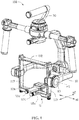
- the frame 11 may bear the load 20 through the mounting assembly 12 and may be driven y a corresponding motor 13 to rotate around a rotation axis.
- the frame 11 may rotate around an axis rl.
- the axis r1 may be a pitch axis of the gimbal 10. It is understood that gimbal 10 may include frames (not shown) rotating around other axes (e.g., a roll axis, a yaw axis) and motors for driving such frames, which are not described in detail.
- the frame 11 may include a substantially rectangular frame shape, and may include a first horizontal frame 111, a second horizontal frame 112, and two vertical frames 113.
- the first horizontal frame 111 may be disposed substantially in parallel with the second horizontal frame 112.
- the two vertical frames 113 may be disposed substantially in parallel.
- the first horizontal frame 111, the second horizontal frame 112 may be substantially perpendicular to the vertical frames 113.
- the first horizontal frame 111 When the imaging device 100 is placed normally, the first horizontal frame 111 may be located at a lower position (in a direction closer to the ground), and the second horizontal frame 112 may be located at an upper position (in a direction away from the ground).
- the guiding segment 1111 may be provided with a tooth strip 1114.
- the length direction of the tooth strip 1114 may be substantially parallel with the length direction of the guiding segment 1111. More specifically, the teeth of the tooth strip 1114 may be slantly disposed relative to the length direction of the tooth strip 1114.
- the tooth strip 1114 may be integrally formed with the guiding segment 1111 or may be separately formed and fixedly connected with the guiding segment 1111.
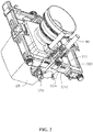
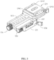
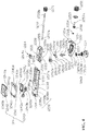
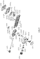
- the mounting assembly 12 may include a first seating body 12a, a second seating body 12b, a first adjusting member 12c, a fastener 12d, and a second adjusting member 12e.
- the first seating body 12a may be provided on the first horizontal frame 111 and may be configured to be slidable along the first horizontal frame 111 in a first direction d1.
- the second seating body 12b may be provided on the first seating body 12a and may be configured to be slidable along the first seating body 12a in a second direction d2.
- the first direction d1 and the second direction d2 may be different and may cross each other at a predetermined angel.
- the first direction d1 may be substantially in parallel with the second direction d2.
- the first seating body 12a may be configured to sleeve-fit with the first horizontal frame 111.
- the first seating body 12a may include a first joining member 121 and a second joining member 122.
- the first joining member 121 and the second joining member 122 may join together to form the first seating body 12a.
- the first joining member 121 may include a first groove 121a
- the second joining member 122 may include a second groove 122a.
- the first groove 121a and the second groove 122a together may form an entire through hole for the first horizontal frame 111 to penetrate through.
- the first joining member 121 may include a first mounting member 1211 and a second mounting member 1212 connected with the first mounting member 1211.
- the first mounting member 1211 may be configured to mount the first adjusting member 12c.
- the second mounting member 1212 may be configured to mount the fastener 12d.
- the first mounting member 1211 and the second mounting member 1212 may be integrally formed.
- the first mounting member 1211 may have a substantial "L" shape. The first mounting member 1211 and the second mounting member 1212 together may enclose to form the first groove 121a.
- the first fitting groove 1215 includes an opening formed at a bottom surface of the first groove 121a.
- the opening allows a portion of the structure of the first adjusting member 12c to protrude out of a surface of the first mounting member 1211 that faces the first mounting member 1211, such that the first adjusting member 12c can couple with the guiding segment 1111 and drive the first seating body 12a to move in the first direction d1.
- the first fitting groove 1215 may include other shapes, as long as the shapes do not affect the first adjusting member 12c to drive the first seating body 12a to move, which are not repeated.
- the first joining member 121 may include a matching depression 1218.
- the matching depression 1218 may be located at an end of the first through hole 1214 facing against the first fitting groove 1215 and may be connected with the first through hole 1214.
- the matching depression 1218 may depress from an outer side surface of the first mounting member 1211.
- the first through hole 1214 may extend from a bottom surface of the matching depression 1218 until to a location connected with the first fitting groove 1215.
- the matching depression 1218 may match with some structure of the first adjusting member 12c to improve the accuracy of mounting and operation.
- the second fitting groove 1217 may have other shapes, as long as the above functions can be realized, which are not repeated.
- the second joining member 122 may be provided with a mounting hole 122c.
- the mounting hole 122c may penetrate from the first end surface 1225 through the second end surface 1226.
- the mounting hole 122c is a threaded hole with internal threads.
- the extending direction of the mounting hole 122c is substantially parallel with the second direction d2.
- the cross section of the protrusion on each side may be a half circle, an oval, a triangle, or a rectangle, etc.
- the protrusion on each side may include a plurality of non-continuous protrusions arranged in the second direction d2.
- the second joining member 122 may include a protruding rib 1228.
- the protruding rib 1228 has a substantial long strip shape and protrudes from the top surface 1221 corresponding to the mounting hole 122c.
- the protruding rib 1228 can increase the structural strength at the mounting hole 122c, preventing damage at the mounting hole 122c due to an excessive force experienced by the second joining member 122.
- the protruding rib 1228 may couple with the second seating body 12b and function as a guiding structure for the movement of the second seating body 12b relative to the first seating body 12a, thereby forming an auxiliary guiding member besides the first guiding member 1227.
- the second seating body 12b may be configured to mount the load 20, and can cause the load 20 to move relative to the first seating body 12a in the second direction.
- the second seating body 12b includes a movable member 123 and a connecting member 124.
- the movable member 123 is configured to movably connect with the first seating body 12a to adjust the mounting location of the load 20.
- the connecting member 124 may connect the load to the second seating body 12b.
- the movable member 123 may have a substantial long strip shape, including a top surface 1231, a bottom surface 1232 opposing the top surface 1231, a first end surface 1233, and a second end surface 1234 opposing the first end surface 1233.
- the bottom surface 1232 faces the first seating body 12a.
- the facing direction of the first end surface 1233 is the same as the facing direction of the first end surface 1225 of the second joining member 122.
- the facing direction of the second end surface 1234 is the same as the facing direction of the second end surface 1226 of the second joining member 122.
- the top surface 1231 may be configured to connect and mount the connecting member 124.
- the movable member 123 may include a second guiding member 1235 corresponding to the first guiding member 1227.
- the second guiding member 1235 may be configured to couple with the first guiding member 1227 to guide the movable direction of the first seating body 12a relative to the second seating body 12b.
- the second guiding member 1235 may include two guiding grooves formed in the movable member 123.
- a depressed opening 123a may be formed at the bottom surface 1232 of the movable member 123.
- the depressed opening 123a may be a substantially rectangular groove.
- the guiding grooves may be long strip shaped grooves formed on opposing inner surfaces of the depressed opening 123a, respectively.
- Each of the guiding grooves has a substantially wedge-shaped groove shape.
- the two guiding grooves form the substantially swallowtail groove shaped second guiding member 1235.
- the shape and location of the second guiding member 1235 may be suitably changed based on specific needs. For example, corresponding to different disposition locations and cross section area shapes of the first guiding member 1227, the disposition locations and the cross section area shapes of the second guiding member 1235 may be different, which are not repeated.
- the movable member 123 may include two load bearing members 1236 disposed opposing each other.
- the load bearing members 1236 may be configured to bear the second adjusting member 12e and allow the second adjusting member 12e to rotate relative to the second seating body 12b.
- the load bearing members 1236 may be disposed at the bottom of the movable member 123 close to the first end surface 1233 and the second end surface 1234, respectively.
- the load bearing members 1236 may be protrusions relative to a bottom surface of the depressed opening 123a.
- the load bearing members 1236 may be substantially parallel with the bottom surface 1232.
- Each of the load bearing members 1236 may be provided with an axis hole 1236a
- the axis hole 1236a may be configured to rotatably couple with the second adjusting member 12e, and at least one axis hole 1236a may be configured to limit the movement of the second adjusting member 12e in the second direction d2.
- the axis hole 1236a closer to the first end surface 1233 may be a through hole, and the axis hole 1236a closer to the second end surface 1234 may be a blocked hole.
- load bearing members 1236 and the movable member 123 may be integrally formed, or may be separately formed and then connected through a connecting member.
- the side-facing opening allows the rotating structure of the connecting member 124 to rotate for a predetermined angle.
- the second mounting structure 1238 may include a fixing hole 1238d located at the top surface 1231 and a positioning pin 1238e.
- the fixing hole 1238d is biasedly disposed from the shaft connecting hole 1238b on the side of the groove 1238c.
- the positioning pin 1238e may be fixedly received in the fixing hole 1238d, with a portion extending out of the fixing hole 1238d.
- the positioning pin 1238e may be configured to locate the mounting location of the connecting member 124 on the movable member 123, and may prevent reversed mounting of the connecting member 124.
- the fixing member 1241 may have a substantially rectangular shape.
- the fixing member 1241 may include a second assembly hole 1241a corresponding to the first assembly hole 1238a. When the fixing member 1241 is mounted to the movable member 123, the second assembly hole 1241 a is aligned with the corresponding first assembly hole 1238a, respectively.
- the fixing member 1241 may include a positioning hole 121b corresponding to the positioning pin 1238e. The positioning hole 1241b may couple with the positioning pin 1238e to locate the mounting location of the fixing member 1241.
- the fixing member 1241 may include a guiding block 1241c and a blocking member 1241d.
- the guiding block 1241c and the blocking member 1241d may be disposed protruding from a side surface of the fixing member 1241 facing away from the movable member 123.
- the guiding block 1241c and the blocking member 1241d may have a substantial long strip shape, and the length directions may be substantially parallel with the first direction d1.
- the end of the guiding block 1241c facing away from the fixing member 1241 slantly and inwardly extends to form a snap-in member 1241g.
- the snap-in member 1241g may snap into the slidable member 1242 and guide the sliding direction of the slidable member 1242.
- the guiding block 1241c includes two separately disposed protruding blocks. It is understood that the guiding block 1241c may be an integral protruding block.
- the blocking member 1241d may be configured to abut and block the locking member 1243, such that the locking member 1243 may couple with the slidable member 1242.
- the fixing member 1241 may include a through hole 1241e at a location near the blocking member 1241d.
- the through hole 1241e allows a portion of the structure of the locking member 1243 to penetrate through and to couple with the slidable member 1242.
- the through hole 1241e may be a rectangular hole, with a length direction substantially parallel with the first direction dl, and a width direction substantially perpendicular to the first direction d1.
- the slidable member 1242 may be configured to connect with the load 20 and to adjust the mounting location of the load 20 on the mounting assembly 12.
- the slidable member 1242 may have a substantially cubic shape.
- the slidable member 1242 may include two snap-fit grooves 1242a.
- the snap-fit grooves 1242a may be disposed on two side surfaces of the slidable member 1242 that face against one another, respectively.
- Each of the snap-fit grooves 1242a may have a substantial long strip shape.
- the length direction of the snap-fit groove 1242a may be substantially parallel with the first direction d1.
- the two snap-fit grooves 1242a may substantially form a structure having a swallowtail groove shape.
- the slidable member 1242 may be provided with a connecting structure 1242b configured to connect and mount the load 20.
- the connecting structure 1242b may be a groove formed in a side surface of the slidable member 1242 that faces against the fixing member 1241.
- the connecting structure 1242b may be a groove having a substantial waist shape.
- the locking member 1243 may include a slidable part 1243a and a driving member 1243b configured to drive the slidable part 1243a to move.
- the slidable part 1243a may include a bottom plate 1243c and a locking block 1243d protruding from the bottom plate 1243c.
- the locking block 1243d protrudes from a side surface of the bottom plate 1243c that faces against the movable member 123 and is disposed at a side closer to the bottom plate 1243c. That is, the slidable part 1243a and the bottom plate 1243c may be connected with one another in a substantial "L" shape.
- the slidable part 1243a may be configured to couple with the receiving depression 1241f and may slide in the receiving depression 1241f.
- the slidable part 1243a may have a substantial square frame shape, including a first side edge 1243e, a second side edge 1243f, and an end wall 1243g.
- the end wall 1243g may be disposed opposing the locking block 1243d.
- the first side edge 1243e and the second side edge 1243f may be opposingly disposed and may be substantially in parallel with one another.
- An end of the locking block 1243d facing against the bottom plate slantly and inwardly extends to form a snap-in member 1243i.
- the snap-in member 1243i may be configured to match with the one of the snap-fit grooves 1242a.
- a side surface of the locking block 1243d facing the blocking member 1241d is formed with an abutting depression 1243j.
- the abutting depression 1243j may be configured to abut an elastic member (not shown) against and between the locking member 1243 and the fixing member 1241.
- the driving member 1243b may include a rotating disk 1243k, a protruding wheel 12431, and an operating member 1243m.
- the protruding wheel 12431 may be located at a side surface of the rotating disk 1243k facing against the movable member 123.
- the operating member 1243m may be configured to connect to the outer circumference surface of the rotating disk 1243k and extend in a direction away from the center of the rotating disk 1243k for a predetermined distance.
- a rotating shaft 1243n is formed at the center of the rotating disk 1243k.
- the rotating shaft 1243n protrudes from a side surface of the rotating disk 1243k facing the movable member 123, and may rotatably couple with the shaft connecting hole 1238b. It is understood that in other embodiments, the rotating disk 1243k may be omitted. Instead, the protruding wheel 12431 and the operating member 1243m may be directly connected with the rotating shaft 1243n.
- an end of the rotating shaft 1253 facing the first knob 1251 may be provided with a pin hole 1253a, the rotating shaft 1253 and the first knob 1251 may be coupled with one another through a pin (not shown) to form a stop-rotation connection. It is understood that the rotating shaft 1253 and the first knob 1251 may form a stop-rotation connection through shape matching.
- an end of the rotating shaft 1253 facing the first driving member 1252 may be a polygon prism, and the first knob 1251 may be provided with a polygon insertion hole that matches with the polygon prism.
- the rotating shaft 1253 may have other shapes, such as oval, plum blossom shape, Chinese character "-" shape, Chinese character "+” shape, or other regular or irregular shapes.
- the first driving member 1252 may include a gear, which may mesh with the tooth strip 1114 of the first horizontal frame 111.
- the first driving member 1252 may include a helical gear, i.e., a gear whose length direction of the tooth slants at a predetermined angle relative to a rotating axis of the gear.
- the first driving member 1252 may mesh with the slanted teeth of the tooth strip 1114 through the helical gear structure, which may increase the meshing area, reduce the engaging gap, and increase the stability and reliability of the transmission.
- the first adjusting member 12c may also include a bearing 1254.
- the bearing 1254 may include a shaft hole 1254a.
- the shaft hole 1254a may rotatably couple with the rotating shaft 1253.
- the first adjusting member 12c may be configured to fixedly connect with the first joining member 121.
- the bearing 1254 may fixedly connect with the first joining member 121 through a threaded connection, gluing, welding, or snap-fitting. In some embodiments, the first bearing 1254 may fixedly connect with a side inner wall of the first fitting groove 1215 facing the first adjusting member 12c.
- the bearing 1254 may be integrally formed with the second joining member 122.
- the bearing 1254 may be omitted, and a shaft hole may be provided directly at the second joining member 122.
- the fastener 12d may be configured to lock the first seating body 12a at the first horizontal frame 111, such that the location of the first seating body 12a relative to the first horizontal frame 111 is locked, and the location of the second seating body 12b relative to the first seating body 12a is locked.
- the fastener 12d may include a first abutting member 1261, a second abutting member 1264, a driving member 1262, and a handle 1263.
- the first abutting member 1261 may be driven by the driving member 1262 to tightly abut against the first horizontal frame 111.
- the second abutting member 1264 may be driven by the driving member 1261 to tightly abut against the second seating body 12b.
- the handle 1263 may allow a user to operate the driving member 1262 to drive the first abutting member 1261 and the second abutting member 1264 to move.
- the first abutting member 1261 may have a substantially triangular prism shape, and may include a first abutting surface 1261a, a first slant surface 1261b, and a bottom surface 1261c.
- the shape of the first abutting surface 1261a may match with the shape of the side surface of the first horizontal frame 111 to increase the abutting contact area with the first horizontal frame 111, thereby increasing the stability of the fixed connection.
- the first slant surface 1261b may slidably couple with the driving member 1262.
- the first abutting member 1261 may be provided with an avoidance member 1261d.
- the avoidance member 1261d may extend throughout the first slant surface 1261b and the bottom surface 1261c. The avoidance member 1261d may enable the first abutting member 1261 to engage with the driving member 1262 and to move toward the first horizontal frame 111.
- the second abutting member 1264 may have a substantially cuboidal shape, including the second abutting surface 1264a facing the second seating body 12b and a fitting surface 1264b that faces against the second abutting surface 1264a.
- the second abutting surface 1264a may tightly abut against the second seating body 12b.
- the fitting surface 1264b may include a fitting hole 1264c configured to couple with the driving member 1262.
- the fitting hole 1264c may couple with the driving member 1262 and may be driven by the driving member 1262 to tightly abut against the second seating body 12b.
- the driving member 1262 may include a stud segment 1262a, a connecting segment 1262b, an abutting-pressing member 1262c located between the stud segment 1262a and the connecting segment 1262b, and a pressing block 1262d.
- the stud segment 1262a may include external threads configured to engage with the internal threads of the fitting hole 1264c. The engagement between the stud segment 1262a and the fitting hole 1264c may enable the stud segment 1262a to drive, when rotating, the first abutting member 1261 to move.
- the connecting segment 1262b may penetrate through the pressing block 1262d to form a stop-rotation connection with the handle 1263.
- the details of the stop-rotation connection may refer to the previous descriptions relating to the stop-rotation connection in the first adjusting member 12c, which are not repeated.
- the abutting-pressing member 1262c may protrude from a circumferential side surface of the stud segment 1262a, forming a substantially ring-shaped protruding edge. When the stud segment 1262a penetrates through the pressing block 1262d, the abutting-pressing member 1262c may abut against the pressing block 1262d.
- the pressing block 1262d may be configured to drive the first abutting member 1261 to tightly abut against the first horizontal frame 111.
- the pressing block 1262d may have a substantially cubic shape.
- the pressing block 1262d may include a first surface 1262e, a second surface 1262f facing against the first surface 1262e, and a second slant surface 1262g fitting with the first slant surface 1261b.
- the first surface 1262e may face the second seating body 12b.
- the second slant surface 1262g may face the first abutting member 1261 and may form a predetermined slant angle with the first surface 1262e and the second surface 1262f.
- the second slant surface 1262g may be formed by cutting two side surfaces of the pressing block 1262d that face against one another.
- the second slant surface 1262g may include two slant surfaces of two sides of the pressing block 1262d that face against one another.
- the second slant surface 1262g may be formed by protrusions that protrude from two side surfaces of the pressing block 1262d that face against one another.
- the handle 1263 may form a stop-rotation connection with the connecting segment 1262b.
- the handle 1263 may allow a user to operate, such that the driving member 1262 can rotate to drive the first abutting member 1261 to move.
- the handle 1263 may include a cap member 1263c, a sleeve-fitting member 1263a, and a handle member 1263b connected with the sleeve-fitting member 1263a.
- the cap member 1263c may form a stop-rotation connection with the connecting segment 1262b.
- the stop-rotation connection may refer to the stop-rotation connection described previously, which is not repeated.
- the external circumferential surface of the cap member 1263c may form a protruding rib 1263d.
- the protruding rib 1263d may include multiple strip-shaped ribs.
- the length direction of the protruding rib 1263d may be substantially parallel with a central axis of the cap member 1263c.
- the sleeve-fitting member 1263a may have a substantial ring shape.
- the inner surface of the sleeve-fitting member 1263a may include a groove 1263e corresponding to the protruding rib 1263d.
- the groove 1263e may couple with the protruding rib 1263d such that the handle member 1263b and the cap member 1263c form a stop-rotation connection.
- the sleeve-fitting member 1263a and the cap member 1263c may form the stop-rotation connection through coupling using other shapes, such as oval, plum blossom shape, Chinese character " -" shape, Chinese character "+” shape, or other regular or irregular shapes.
- the sleeve-fitting member 1263a and the cap member 1263c may form the stop-rotation connection through a stop-rotation pin that penetrates through the sleeve-fitting member 1263a and the cap member 1263c.
- the sleeve-fitting member 1263a and the cap member 1263c may be integrally formed.
- the handle member 1263b may extend for a predetermined distance toward an outer side of the sleeve-fitting member 1263a, which makes it more labor-saving when operating the handle 1263.
- the first seating body 12a may include a blocking cover 129.
- the blocking cover 129 may prevent the handle 1263 from falling off from the driving member 1262.
- the blocking cover 129 may have a substantial disk shape that has an internal depression.
- the blocking cover 129 may cover the first seating body 12a and may form a gap with the first seating body 12a, such that the handle member 1263b may extend out of the blocking cover 129, which makes the operation convenient.
- the blocking cover 129 may cover the first joining member 121 and form a gap with the first joining member 121.
- the second adjusting member 12e may drive the second seating body 12b to move relative to the first seating body 12a, to adjust the mounting location of the second seating body 12b relative to the first seating body 12a.
- the second adjusting member 12e may include a second knob 1271 and a second driving member 1272.
- the second knob 1271 may drive the second driving member 1272 to rotate.
- the second driving member 1272 may be a lead screw having external threads. The external threads of the second driving member 1272 may engage with the internal threads of the mounting hole 122c.
- the second driving member 1272 may include a first connecting end 1272a and a second connecting end 1272b facing against the first connecting end 1272a.
- the first connecting end 1272a and the second connecting end 1272b may rotatably connect the second driving member 1272 with the second seating body 12b.
- the second knob 1271 may form a stop-rotation connection with the second connecting end 1272b.
- the stop-rotation connection may refer to the above stop-rotation connection structure described previously, which is not repeated.
- the first adjusting member 12c and the fastener 12d may penetrate the first through hole 1214.
- the bearing 1254 may be fixed at the first joining member 121.
- the first driving member 1252 may be located in the first fitting groove 1215. A portion of the first driving member 1252 may protrude from a bottom surface of the first groove 121a.
- the first knob 1251 may be connected with an end of the rotating shaft 1253 penetrating through the first through hole 1214. The first knob 1251 may form a stop-rotation connection with the rotating shaft 1253.
- the first abutting member 1261 and the pressing block 1262d may be disposed in the second fitting groove 1217.
- the first slant surface 1261b and the second slant surface 1262g may fit with one another.
- the second abutting member 1264 may be received in the receiving groove 122b.
- the connecting segment 1262b may penetrate through the through hole 1262i of the pressing block and the second through hole 1216 of the first seating body 12a in sequence to form a stop-rotation connection with the handle 1263.
- the stud segment 1262a may be connected with the fitting hole 1264c of the second abutting member 1264.
- the blocking cover 129 may cover the handle 1263 and connect with the first seating body 12a.
- the first joining member 121 and the second joining member 122 may be joined from two sides of the first horizontal frame 111.
- the joined first joining member 121 and second joining member 122 may be sleeve-fit on the first horizontal frame 111.
- the first driving member 1252 may mesh with the tooth strip of the guiding segment 1111.
- the first joining member 121 and the second joining member 122 may be joined together through bolts, gluing parts, or snap-fitting parts, etc.
- the connecting member 124 of the second seating body 12b may be mounted to the movable member 123.
- the rotating shaft 1243n of the driving member 1243b of the locking member 1243 may be inserted into the shaft connecting hole 1238b.
- the rotating disk 1243k may be received in the groove 1238c.
- the operating member 1243m may extend out of the second seating body 12b from an opening on a side of the groove 1238c.
- the bottom plate of the slidable part 1243a may be received in the receiving depression 1241f.
- the locking block 1243d may penetrate through the through hole 1241e and protrude from a side surface of the fixing member 1241 that faces the slidable member 1242.
- the slidable member 1242 may be slidably connected with the fixing member 1241.
- the snap-in member 1241g of the slidable member 1242 and the snap-in member 1243i of the locking member 1243 may respectively snap into the snap-fit groove 1242a.
- the first seating body 12a and the second seating body 12b may be slidably connected.
- the second joining member 122 may be grouped into the depressed opening 123a of the movable member 123.
- the first guiding member 1227 may respectively snap-fit with the second guiding member 1235, such that the second seating body 12b may slide relative to the first seating body 12a.
- the second driving member 1272 of the second adjusting member 12e may penetrate through the mounting hole 122c.
- the first connecting end 1272a and the second connecting end 1272b may respectively rotatably connect with the load bearing member 1236.
- the second knob 1271 and the second connecting end 1272b may form a stop-rotation connection.
- the first knob 1251 and the second knob 1271 are located on a same side of the mounting assembly 12. That is, the operating parts of the first adjusting member 12c and the second adjusting member 12e that are operated by a user may be located on the same side of the mounting assembly 12, which makes adjusting the operations convenient.
- the load 20 may be fixedly mounted to the slidable member 1242.
- the load 20 may adjust the mounting location relative to the second seating body 12b through the slidable member 1242.
- the driving member 1243b may be rotated.
- the protruding wheel 12431 may abut against the end wall 1243g of the bottom plate 1243c and drive the bottom plate 1243c to slide relative to the slidable part 1243a.
- the locking block 1243d driven by the bottom plate 1243c, may move toward the guiding block 1241c of the fixing member 1241, and tightly clamp the slidable member 1242 together with the guiding block 1241c, to fix the mounting location of the slidable member 1242 relative to the fixing member 1241, and to simultaneously fix the mounting location of the load 20 relative to the second seating body 12b.
- the imaging device 100 may adjust the location of the load 20 in the first direction d1 through the first adjusting member 12c, and adjust the location of the load 20 in the second direction d2 through the second adjusting member 12e, such that the center of gravity of the load 20 falls on the rotating axis of the gimbal 10. This may avoid the effect of an unexpected torque on the motor of the gimbal, guarantee the operational life time of the gimbal, and improve the imaging user experience.
- the fastener 12d may be operated, such that the first abutting member 1261 may fittingly and tightly abut against a side surface of the guiding segment 1111, to fix the relative locations of the first seating body 12a and the first horizontal frame 111.
- the second abutting member 1264 may tightly abut against the second seating body 12b to fix the relative locations of the second seating body 12b and the first seating body 12a.
- the fastener 12d may lock the first seating body 12a and the second seating body 12b through the following detailed manner: when rotating the connecting segment 1262b in a predetermined direction through the handle 1263, the stud segment 1262a may drive, through threads transmission, the second abutting member 1264 to move toward the second seating body 12b to tightly abut against the second seating body 12b. After the second abutting member 1264 tightly abuts against the second seating body 12b, the connecting segment 1262b may move away from the second seating body 12b through transmission using the threads. The abutting-pressing member 1262c may abut against the pressing block 1262d to move away from the second seating body 12b.
- the first adjusting member 12c may be provided on the first seating body 12a, and may mesh with the tooth strip 1114 provided on the first horizontal frame 111 to drive the first seating body 12a to move. It is understood that the first adjusting member 12c may also be provided on the first horizontal frame 111, and the tooth strip 1114 may be provided on the first seating body 12a.
- first guiding member 1227 and the structure of the second guiding member 1235 may be exchanged. That is, the second seating body 12b may form a structure similar to the structure of the first guiding member 1227, and the first seating body 12a may form a structure similar to the structure of the second guiding member 1235.
Landscapes
- Engineering & Computer Science (AREA)
- General Engineering & Computer Science (AREA)
- Mechanical Engineering (AREA)
- Physics & Mathematics (AREA)
- General Physics & Mathematics (AREA)
- Accessories Of Cameras (AREA)
- Connection Of Plates (AREA)
Claims (15)
- Kardanaufhängungslastmontageanordnung, die dazu ausgelegt ist, gleitbar an einem Kardanaufhängungsrahmen (11, 111-113) montiert zu werden, um einen Schwerpunkt einer Last (20), die an der Kardanaufhängungslastmontageanordnung montiert ist, einzustellen, wobei die Kardanaufhängungslastmontageanordnung einen ersten Sitzkörper (12a), einen zweiten Sitzkörper (12b), der gleitbar mit dem ersten Sitzkörper (12a) verbunden werden kann, und ein Befestigungselement (12d) umfasst, wobei der erste Sitzkörper (12a) dazu ausgelegt ist, mit dem Kardanaufhängungsrahmen (11, 111-113) verbunden zu werden und in eine erste Richtung (d1) zu gleiten, der zweite Sitzkörper (12b) dazu ausgelegt ist, die Last (20) zu montieren, der zweite Sitzkörper (12b) auf dem ersten Sitzkörper (12a) in eine zweite Richtung (d2) gleiten kann, das Befestigungselement (12d) mit dem ersten Sitzkörper (12a) verbunden ist und einen Montageort des ersten Sitzkörpers (12a) relativ zum Kardanaufhängungsrahmen (11, 111-113) und einen Montageort des zweiten Sitzkörpers (12b) relativ zum ersten Sitzkörper (12a) gleichzeitig verriegeln kann;
dadurch gekennzeichnet, dass
die Kardanaufhängungslastmontageanordnung ferner ein erstes Einstellelement (12c) umfasst, wobei das erste Einstellelement (12c) an einem des ersten Sitzkörpers (12a) und des Kardanaufhängungsrahmens (11, 111-113) angeordnet werden kann und den ersten Sitzkörper (12a) zum Bewegen antreiben kann, um einen relativen Ort des ersten Sitzkörpers (12a) relativ zum Kardanaufhängungsrahmen (11, 111-113) einzustellen. - Kardanaufhängungslastmontageanordnung nach Anspruch 1, dadurch gekennzeichnet, dass: das erste Befestigungselement (12d) ein erstes Anstoßelement (1261), ein zweites Anstoßelement (1264) und ein Antriebselement (1243b, 1252, 1261, 1262, 1272) umfasst, das erste Anstoßelement (1261) und das zweite Anstoßelement (1264) bewegbar am ersten Sitzkörper (12a) bereitgestellt werden können, das Antriebselement (1243b, 1252, 1261, 1262, 1272) an das erste Anstoßelement (1261) und das zweite Anstoßelement (1264) anstößt, das Antriebselement (1243b, 1252, 1261, 1262, 1272) das erste Anstoßelement (1261), um dicht am Kardanaufhängungs(10)-Rahmen (11, 111-113) anzuliegen, und das zweite Anstoßelement (1264), um dicht am zweiten Sitzkörper (12b) anzuliegen, gleichzeitig antreiben kann, um den Montageort des ersten Sitzkörpers (12a) relativ zum Kardanaufhängungs(10)-Rahmen (11, 111-113) und den Montageort des zweiten Sitzkörpers (12b) relativ zum ersten Sitzkörper (12a) gleichzeitig zu verriegeln.
- Kardanaufhängungslastmontageanordnung nach Anspruch 2, dadurch gekennzeichnet, dass: das Antriebselement (1243b, 1252, 1261, 1262, 1272) das erste Anstoßelement (1261) und das zweite Anstoßelement (1264) in verschiedene Richtungen antreiben kann, wobei vorzugsweise:
eine Richtung, in die das Antriebselement (1243b, 1252, 1261, 1262, 1272) das erste Anstoßelement (1261) antreibt im Wesentlichen senkrecht zu einer Richtung verläuft, in die das Antriebselement (1243b, 1252, 1261, 1262, 1272) das zweite Anstoßelement (1264) antreibt. - Kardanaufhängungslastmontageanordnung nach Anspruch 2, dadurch gekennzeichnet, dass: der erste Sitzkörper (12a) eine Einsetznut (1215, 1217) und eine Aufnahmenut (122b) umfasst, die Einsetznut (1215, 1217) eine Öffnung (123a, 1243h) umfasst, die dem Kardanaufhängungsrahmen (11, 111-113) zugewandt ist, die Aufnahmenut (122b) eine Öffnung (123a, 1243h) umfasst, die dem zweiten Sitzkörper (12b) zugewandt ist, das erste Anstoßelement (1261) bewegbar in die Einsetznut (1215, 1217) aufgenommen werden kann, das zweite Anstoßelement (1264) bewegbar in die Aufnahmenut (122b) aufgenommen werden kann, das Antriebselement (1243b, 1252, 1261, 1262, 1272) das erste Anstoßelement (1261) derart antreiben kann, dass es sich aus der Öffnung (123a, 1243h) der Einsetznut (1215, 1217) heraus erstreckt, derart, dass das erste Anstoßelement (1261) dicht am Kardanaufhängungsrahmen (11, 111-113) anliegt, und das zweite Anstoßelement (1264) derart antreiben kann, dass es sich aus der Öffnung (123a, 1243h) der Aufnahmenut (122b) heraus erstreckt, derart, dass das zweite Anstoßelement (1264) dicht am zweiten Sitzkörper (12b) anliegt.
- Kardanaufhängungslastmontageanordnung nach Anspruch 4, dadurch gekennzeichnet, dass: das Antriebselement (1243b, 1252, 1261, 1262, 1272) ein Bolzensegment (1262a), ein Verbindungssegment (1262b), das fest mit dem Bolzensegment (1262a) verbunden ist, ein Anstoßdruckelement (1262c), das sich zwischen dem Bolzensegment (1262a) und dem Verbindungssegment (1262b) befindet, und einen Druckblock (1262d) umfasst, das Bolzensegment (1262a) mit dem zweiten Anstoßelement (1264) über ein Gewinde verbunden ist und das zweite Anstoßelement (1264) derart antreibt, dass es sich in einer Gewindeübertragungsweise bewegt, das Verbindungssegment (1262b) den Druckblock (1262d) drehbar durchdringen kann, derart, dass das Anstoßdruckelement (1262c) am Druckblock (1262d) anliegt und gegen denselben drückt, der Druckblock (1262d) am ersten Anstoßelement (1261) anliegt, das Anstoßdruckelement (1262c) derart gegen den Druckblock (1262d) drückt, dass er sich durch eine Gegenreaktion, die vom Gewinde übertragen wird, bewegt, wodurch das erste Anstoßelement (1261) zum Bewegen angetrieben wird.
- Kardanaufhängungslastmontageanordnung nach Anspruch 5, dadurch gekennzeichnet, dass: das erste Anstoßelement (1261) und der Druckblock (1262d) zum Übertragen über schräge Flächen gekoppelt sind, derart, dass eine Bewegungsrichtung des ersten Anstoßelements (1261) und eine Bewegungsrichtung des Druckblocks (1262d) verschieden sind,
oder
dadurch gekennzeichnet, dass: das erste Anstoßelement (1261) eine erste Anstoßfläche (1261a) und eine erste schräge Fläche (1261b), die relativ zur ersten Anstoßfläche (1261a) geneigt ist, umfasst, der Druckblock (1262d) eine zweite schräge Fläche (1262g) umfasst, die der ersten schrägen Fläche (1261b) entspricht, die erste Anstoßfläche (1261a) dicht am Kardanaufhängungs(10)-Rahmen (11, 111-113) anliegen kann und die zweite schräge Fläche (1262g) des Druckblocks (1262d) an der ersten schrägen Fläche (1261b) anliegt, oder
dadurch gekennzeichnet, dass: das erste Anstoßelement (1261) ein Vermeidungselement (1261d) umfasst, wobei das Vermeidungselement (1261d) die erste schräge Fläche (1261b) durchdringt, das Vermeidungselement (1261d) es dem ersten Anstoßelement (1261) ermöglichen kann, das Verbindungselement (1262b) zu vermeiden und an den Druckblock (1262d) zu koppeln,
oder
dadurch gekennzeichnet, dass: der Druckblock (1262d) eine Vertiefung (1218, 1241f, 1243j, 1262h) und ein Durchgangsloch (1214, 1216, 1241e, 1262i) umfasst, die Vertiefung (1218, 1241f, 1243j, 1262h) sich auf einer Seitenfläche (1223, 1224) des Druckblocks (1262d), die dem zweiten Anstoßelement (1264) zugewandt ist, befindet, das Durchgangsloch (1214, 1216, 1241e, 1262i) eine Seitenfläche (1223, 1224) des Druckblocks (1262d), die dem zweiten Anstoßelement (1264) zugewandt ist, von einem Boden der Vertiefung (1218, 1241f, 1243j, 1262h) ganz durchdringt, das Verbindungssegment (1262b) das Durchgangsloch (1214, 1216, 1241e, 1262i) drehbar durchdringen kann, das Anstoßdruckelement (1262c) am Boden der Vertiefung (1218, 1241f, 1243j, 1262h) anliegt und gegen denselben drückt. - Kardanaufhängungslastmontageanordnung nach Anspruch 5, dadurch gekennzeichnet, dass: das Antriebselement (1243b, 1252, 1261, 1262, 1272) einen Griff (1263) umfasst, der Griff (1263) und das Verbindungssegment (1262b) ein Ende (1272a, 1272b) des Druckblocks (1262d) durchdringen, um eine Drehungsbeendigungsverbindung zu bilden, der Griff (1263) betätigt werden kann, um das Bolzensegment (1262a) zu drehen.
- Kardanaufhängungslastmontageanordnung nach Anspruch 7, dadurch gekennzeichnet, dass: der erste Sitzkörper (12a) eine Blockierungsabdeckung (129) umfasst, die Blockierungsabdeckung (129) den ersten Sitzkörper (12a) abdeckt und mit dem ersten Sitzkörper (12a) einen Spalt bildet, das Hülseneinsetzelement (1263a) sich an der Blockierungsabdeckung (129) befindet, das Griffelement (1263b) sich vom Spalt aus der Blockierungsabdeckung (129) heraus erstreckt.
- Kardanaufhängungslastmontageanordnung nach Anspruch 1, dadurch gekennzeichnet, dass: der erste Sitzkörper (12a) ein erstes Führungselement (1127, 1227) umfasst, der zweite Sitzkörper (12b) ein zweites Führungselement (1235) umfasst, das dem ersten Führungselement (1127, 1227) entspricht, der erste Sitzkörper (12a) und der zweite Sitzkörper (12b) sich durch das erste Führungselement (1127, 1227) und das zweite Führungselement (1235) gleitbar miteinander verbinden können,
wobei vorzugsweise:
das erste Führungselement (1127, 1227) durch streifenförmige Vorsprünge auf zwei Seitenflächen (1223, 1224) des ersten Sitzkörpers (12a), die einander zugewandt sind, gebildet wird, das zweite Führungselement (1235) durch streifenförmige Nuten gebildet wird, die an zwei Innenwand des zweiten Sitzkörpers (12b) gebildet sind, die einander zugewandt sind. - Kardanaufhängungslastmontageanordnung nach Anspruch 1, dadurch gekennzeichnet, dass: der zweite Sitzkörper (12b) ein bewegbares Element (123) und ein Verbindungselement (124) umfasst, das bewegbare Element (123) sich gleitbar mit dem ersten Sitzkörper (12a) verbinden kann, das Verbindungselement (124) sich zum Montieren der Last (20) mit dem bewegbaren Element (123) verbindet.
- Kardanaufhängungslastmontageanordnung nach Ansprüchen 10, dadurch gekennzeichnet, dass: das bewegbare Element (123) eine erste Montagestruktur (1237) und eine zweite Montagestruktur (1238) umfasst, die erste Montagestruktur (1237) dazu ausgelegt ist, eine Gegengewichtsanordnung (40) zu montieren, das Verbindungselement (124) über die zweite Montagestruktur (1238) mit dem bewegbaren Element (123) verbunden ist,
oder wobei vorzugsweise:
das Verbindungselement (124) ein Fixierelement (1241), ein gleitbares Element (1242) und ein Verriegelungselement (1243) umfasst, das Fixierelement (1241) fest mit dem bewegbaren Element (123) verbunden ist, das gleitbare Element (1242) sich gleitbar mit dem Fixierelement (1241) verbinden kann, das Verriegelungselement (1243) am Fixierelement (1241) bereitgestellt ist und sich relativ zum Fixierelement (1241) bewegen kann, um das gleitbare Element (1242) zu verriegeln oder die Verriegelung des gleitbaren Elements (1242) zu lösen. - Kardanaufhängungslastmontageanordnung nach Anspruch 1, dadurch gekennzeichnet, dass: sie ferner ein zweites Einstellelement (12e) umfasst, das zweite Einstellelement (12e) mit dem ersten Sitzkörper (12a) und dem zweiten Sitzkörper (12b) verbunden ist und den zweiten Sitzkörper (12b) zum Bewegen relativ zum ersten Sitzkörper (12a) antreiben kann.
- Kardanaufhängung (10), die einen Rahmen (11, 111-113), eine Motoranordnung, die den Rahmen (11, 111-113) zum Drehen antreibt, und eine Kardanaufhängungslastmontageanordnung umfasst, wobei die Kardanaufhängungslastmontageanordnung am Rahmen (11, 111-113) bereitgestellt und dadurch gekennzeichnet ist, dass: die Kardanaufhängungslastmontageanordnung die in einem der Ansprüche 1-12 beschriebene Kardanaufhängungslastmontageanordnung ist.
- Kardanaufhängung (10) nach Anspruch 13, dadurch gekennzeichnet, dass: die erste Richtung parallel zu einer Nickachse der Kardanaufhängung (10) verläuft und/oder die zweite Richtung parallel zu einer Rollachse der Kardanaufhängung (10) verläuft.
- Bildgebungsvorrichtung (100), die eine Kardanaufhängung (10) und eine Bildgebungsanordnung, die an der Kardanaufhängung (10) montiert ist, umfasst, wobei die Kardanaufhängung (10) einen Rahmen (11, 111-113) und eine Kardanaufhängungslastmontageanordnung umfasst, dadurch gekennzeichnet, dass: die Kardanaufhängungslastmontageanordnung eine in einem der Ansprüche 1-12 beschriebene Kardanaufhängungslastmontageanordnung ist.
Applications Claiming Priority (1)
| Application Number | Priority Date | Filing Date | Title |
|---|---|---|---|
| PCT/CN2016/112804 WO2018119806A1 (zh) | 2016-12-28 | 2016-12-28 | 云台负载安装组件、云台及拍摄设备 |
Publications (3)
| Publication Number | Publication Date |
|---|---|
| EP3564573A1 EP3564573A1 (de) | 2019-11-06 |
| EP3564573A4 EP3564573A4 (de) | 2020-08-19 |
| EP3564573B1 true EP3564573B1 (de) | 2021-07-14 |
Family
ID=59431523
Family Applications (1)
| Application Number | Title | Priority Date | Filing Date |
|---|---|---|---|
| EP16925327.5A Active EP3564573B1 (de) | 2016-12-28 | 2016-12-28 | Schwenk- neige-lastmontageanordnung, schwenk-neige-vorrichtung und kameravorrichtung |
Country Status (4)
| Country | Link |
|---|---|
| US (1) | US11442343B2 (de) |
| EP (1) | EP3564573B1 (de) |
| CN (2) | CN109723942B (de) |
| WO (1) | WO2018119806A1 (de) |
Families Citing this family (18)
| Publication number | Priority date | Publication date | Assignee | Title |
|---|---|---|---|---|
| CN109695802B (zh) * | 2016-12-28 | 2021-09-07 | 深圳市大疆灵眸科技有限公司 | 云台负载安装组件、云台及拍摄设备 |
| WO2018119806A1 (zh) * | 2016-12-28 | 2018-07-05 | 深圳市大疆灵眸科技有限公司 | 云台负载安装组件、云台及拍摄设备 |
| USD828434S1 (en) * | 2016-12-28 | 2018-09-11 | Sz Dji Osmo Technology Co., Ltd. | Gimbal |
| WO2018119802A1 (zh) * | 2016-12-28 | 2018-07-05 | 深圳市大疆灵眸科技有限公司 | 云台框架及具有该云台框架的云台和拍摄装置 |
| CN110809688B (zh) * | 2018-08-01 | 2021-08-13 | 深圳市大疆创新科技有限公司 | 云台及云台系统 |
| CN109027566B (zh) * | 2018-09-27 | 2024-08-02 | 桂林智神信息技术股份有限公司 | 稳定器用快装装置及稳定器 |
| CN111140745B (zh) * | 2019-12-27 | 2021-09-28 | 诚瑞光学(常州)股份有限公司 | 摄像装置、电子设备及电子设备的使用方法 |
| CN111255987B (zh) * | 2020-01-21 | 2020-12-25 | 中国科学院西安光学精密机械研究所 | 一种具备环境适应性的视轴可调多负载通用式载物装置 |
| FR3107754B1 (fr) * | 2020-02-27 | 2022-03-18 | Xyzed | Lyre motorisée pour vidéo projecteur |
| US11549637B2 (en) | 2020-05-11 | 2023-01-10 | Honeywell International Inc. | Multi-rotation gimbal assembly and mobile platform incorporating the same |
| CN113048350A (zh) * | 2021-04-30 | 2021-06-29 | 深圳市小隼智创科技有限公司 | 一种锁定结构及调节支架 |
| CN113464814B (zh) * | 2021-06-17 | 2022-08-23 | 四川工商职业技术学院 | 一种用于机房的具备自动识别的图像识别机器人 |
| CN113643956B (zh) * | 2021-08-11 | 2023-09-29 | 长春电子科技学院 | 一种光电子倍增器 |
| WO2023035117A1 (zh) * | 2021-09-07 | 2023-03-16 | 深圳市大疆创新科技有限公司 | 调平装置、手持云台、拍摄设备及可移动平台 |
| CN113905162B (zh) * | 2021-09-29 | 2024-07-16 | 中国通信建设集团有限公司河南省通信服务分公司 | 防外力施工智慧盯防系统 |
| CN114576480A (zh) * | 2022-01-18 | 2022-06-03 | 航天科工空间工程发展有限公司 | 一种用于空间观测的设备 |
| KR102750690B1 (ko) * | 2022-04-04 | 2025-01-06 | 최채휘 | 필름 검사 장비용 카메라 홀더 |
| CN116608379A (zh) * | 2023-05-31 | 2023-08-18 | 深圳市铁头科技有限公司 | 一种横竖切换结构、连接机构及拍摄设备 |
Family Cites Families (39)
| Publication number | Priority date | Publication date | Assignee | Title |
|---|---|---|---|---|
| SU996787A1 (ru) * | 1981-04-30 | 1983-02-15 | Киевская Ордена Ленина Киностудия Художественных Фильмов Им.А.П.Довженко | Устройство дл креплени на корпусе оператора ручного киносъемочного аппарата |
| US4796846A (en) * | 1987-06-01 | 1989-01-10 | Automated Medical Products, Corporation | Retaining device for a surgical instrument |
| KR970006926Y1 (ko) * | 1992-04-24 | 1997-07-09 | 박경팔 | 음극선관의 화면특성 측정 수단의 이송장치 |
| US6068223A (en) * | 1997-11-25 | 2000-05-30 | Panavision, Inc. | Position adjustable grip support for motion picture camera |
| US6196504B1 (en) * | 1998-07-09 | 2001-03-06 | Maurice W. Lemke | Positive-lock-and-release device for camera mounting |
| US20040223078A1 (en) * | 2003-05-09 | 2004-11-11 | Adam Zadok | Support for hand held video camera |
| US7077582B2 (en) * | 2003-08-20 | 2006-07-18 | Johnson Joseph M | Quick-release clamp for photographic equipment |
| DE202005001542U1 (de) * | 2005-02-01 | 2005-03-31 | Moeller Thomas | Stativkopf zur Anbringung einer Kamera und Nodalpunkt-Justierung |
| US8128295B2 (en) * | 2008-12-19 | 2012-03-06 | Stephen Pizzo | Hand held camera mount |
| CN201487489U (zh) * | 2009-06-30 | 2010-05-26 | 林松国 | 云台快装板锁紧机构 |
| JP2014023075A (ja) * | 2012-07-23 | 2014-02-03 | Astro Design Inc | ビューファインダ支持装置 |
| DE102012018755A1 (de) * | 2012-09-21 | 2014-03-27 | Chrosziel Gmbh | Kamera-stativsystem mit fixierrahmen |
| US9046743B2 (en) * | 2012-12-06 | 2015-06-02 | Kadir Koymen | Slider support member |
| CN203384588U (zh) * | 2013-06-18 | 2014-01-08 | 陈世棠 | 摄影手持稳定架专用云台 |
| US9574703B2 (en) * | 2013-08-15 | 2017-02-21 | Freefly Systems, Inc. | Hand-held or vehicle mounted camera stabilization system |
| WO2015055850A2 (en) * | 2013-10-18 | 2015-04-23 | Scott Carthey | A stabiliser |
| US9201291B2 (en) * | 2013-12-31 | 2015-12-01 | Tom Jorgenson | Camera mounting device |
| US20150308618A1 (en) * | 2014-03-12 | 2015-10-29 | Koncept Innovators, LLC. | Vest-mounted gimbal support, and a method for its use |
| CN204062364U (zh) * | 2014-06-27 | 2014-12-31 | 深圳市大疆创新科技有限公司 | 云台 |
| CN104981644B (zh) * | 2014-06-27 | 2017-06-30 | 深圳市大疆灵眸科技有限公司 | 锁紧装置及其使用的云台 |
| CN105517647B (zh) * | 2014-06-27 | 2018-02-02 | 深圳市大疆灵眸科技有限公司 | 一种连接装置及云台设备 |
| CN203963419U (zh) * | 2014-06-27 | 2014-11-26 | 深圳市大疆创新科技有限公司 | 锁紧装置及其使用的云台 |
| CN203907156U (zh) * | 2014-06-27 | 2014-10-29 | 深圳市大疆创新科技有限公司 | 云台 |
| WO2015196484A1 (zh) * | 2014-06-27 | 2015-12-30 | 深圳市大疆创新科技有限公司 | 镜头支架组件及其使用的云台 |
| WO2016000262A1 (zh) * | 2014-07-04 | 2016-01-07 | 深圳市大疆创新科技有限公司 | 配重组件、使用该配重组件的配重机构及云台 |
| CN104884856B (zh) * | 2014-08-13 | 2016-10-12 | 深圳市大疆创新科技有限公司 | 云台 |
| CN105518370B (zh) * | 2014-10-31 | 2018-02-02 | 深圳市大疆灵眸科技有限公司 | 横滚轴组件及其使用的云台 |
| EP3862614A1 (de) * | 2014-11-28 | 2021-08-11 | SZ DJI Technology Co., Ltd. | Translationsachsenanordnung und kopf damit |
| CN105518757B (zh) * | 2015-01-06 | 2018-06-12 | 深圳市大疆灵眸科技有限公司 | 云台遥控器及采用该云台遥控器的手持云台 |
| PL226754B1 (pl) * | 2015-03-20 | 2017-09-29 | Inst Tech Eksploatacji Państwowy Inst Badawczy | Zespół pozycjonera modułu wizyjnego zwłaszcza whybrydowej głowicy wizyjnej |
| CN107407863A (zh) * | 2015-04-07 | 2017-11-28 | 加勒特·W·布朗 | 用于负载稳定器的平衡支撑接口 |
| US9749522B2 (en) * | 2015-06-02 | 2017-08-29 | Alan Holmes | Tracking device for portable astrophotography of the night sky |
| WO2017107088A1 (zh) * | 2015-12-23 | 2017-06-29 | 深圳市大疆创新科技有限公司 | 支撑机构及使用该支撑机构的调整装置以及云台 |
| EP3411620A4 (de) * | 2016-02-01 | 2019-01-23 | SZ DJI Technology Co., Ltd. | Systeme und verfahren zur nutzlaststabilisierung |
| WO2018119806A1 (zh) * | 2016-12-28 | 2018-07-05 | 深圳市大疆灵眸科技有限公司 | 云台负载安装组件、云台及拍摄设备 |
| CN109695802B (zh) * | 2016-12-28 | 2021-09-07 | 深圳市大疆灵眸科技有限公司 | 云台负载安装组件、云台及拍摄设备 |
| CN109751492B (zh) * | 2016-12-28 | 2021-07-20 | 深圳市大疆灵眸科技有限公司 | 云台框架及具有该云台框架的云台和拍摄装置 |
| WO2018119802A1 (zh) * | 2016-12-28 | 2018-07-05 | 深圳市大疆灵眸科技有限公司 | 云台框架及具有该云台框架的云台和拍摄装置 |
| CN206439585U (zh) * | 2016-12-28 | 2017-08-25 | 深圳市大疆灵眸科技有限公司 | 负载支架及具有该负载支架的云台 |
-
2016
- 2016-12-28 WO PCT/CN2016/112804 patent/WO2018119806A1/zh not_active Ceased
- 2016-12-28 CN CN201910102852.4A patent/CN109723942B/zh not_active Expired - Fee Related
- 2016-12-28 EP EP16925327.5A patent/EP3564573B1/de active Active
- 2016-12-28 CN CN201680004164.9A patent/CN107002939B/zh not_active Expired - Fee Related
-
2019
- 2019-06-27 US US16/454,672 patent/US11442343B2/en active Active
Also Published As
| Publication number | Publication date |
|---|---|
| US20190317386A1 (en) | 2019-10-17 |
| EP3564573A4 (de) | 2020-08-19 |
| EP3564573A1 (de) | 2019-11-06 |
| CN109723942A (zh) | 2019-05-07 |
| WO2018119806A1 (zh) | 2018-07-05 |
| CN107002939B (zh) | 2019-03-12 |
| US11442343B2 (en) | 2022-09-13 |
| CN109723942B (zh) | 2021-05-14 |
| CN107002939A (zh) | 2017-08-01 |
Similar Documents
| Publication | Publication Date | Title |
|---|---|---|
| EP3564573B1 (de) | Schwenk- neige-lastmontageanordnung, schwenk-neige-vorrichtung und kameravorrichtung | |
| US10935178B2 (en) | Gimbal load mounting assembly, gimbal, and imaging device | |
| CN107110418B (zh) | 云台负载安装组件、云台及拍摄设备 | |
| US10054842B2 (en) | Gimbal | |
| US11252312B2 (en) | Lens bracket assembly and gimbal used therewith | |
| US9657897B2 (en) | Connecting device and a gimbal apparatus | |
| US10533698B2 (en) | Locking device and gimbal having the locking device | |
| US11035438B2 (en) | Transmission mechanism, follow focus, follow focus actuator, and imaging device | |
| US20250164864A1 (en) | Foldable mounting device and method of operating the same | |
| US20160041454A1 (en) | Camera mounting device | |
| WO2019134398A1 (zh) | 手持云台 | |
| US10890831B2 (en) | Gimbal structure | |
| WO2019000201A1 (zh) | 云台结构及具有该云台结构的云台、拍摄组件 | |
| EP3726275B1 (de) | System und verfahren für einen binokularen stativadapter mit automatischer verriegelung | |
| WO2022141451A1 (zh) | 增稳机构、增稳装置及拍摄设备 | |
| CN215636138U (zh) | 手持云台 | |
| US20060093345A1 (en) | Positioning structure of emergency power supply for use in a camera device | |
| CN206594432U (zh) | 云台负载安装组件、云台及拍摄设备 | |
| WO2018068186A1 (en) | Mount for a camera | |
| WO2023097509A1 (zh) | 连接支架、锁定机构及增稳系统 | |
| CN117063003A (zh) | 手持云台及云台组件 | |
| KR20170010348A (ko) | 광학기기 회전장치용 마찰조정부 |
Legal Events
| Date | Code | Title | Description |
|---|---|---|---|
| STAA | Information on the status of an ep patent application or granted ep patent |
Free format text: STATUS: THE INTERNATIONAL PUBLICATION HAS BEEN MADE |
|
| PUAI | Public reference made under article 153(3) epc to a published international application that has entered the european phase |
Free format text: ORIGINAL CODE: 0009012 |
|
| STAA | Information on the status of an ep patent application or granted ep patent |
Free format text: STATUS: REQUEST FOR EXAMINATION WAS MADE |
|
| 17P | Request for examination filed |
Effective date: 20190515 |
|
| AK | Designated contracting states |
Kind code of ref document: A1 Designated state(s): AL AT BE BG CH CY CZ DE DK EE ES FI FR GB GR HR HU IE IS IT LI LT LU LV MC MK MT NL NO PL PT RO RS SE SI SK SM TR |
|
| AX | Request for extension of the european patent |
Extension state: BA ME |
|
| DAV | Request for validation of the european patent (deleted) | ||
| DAX | Request for extension of the european patent (deleted) | ||
| A4 | Supplementary search report drawn up and despatched |
Effective date: 20200720 |
|
| RIC1 | Information provided on ipc code assigned before grant |
Ipc: F16M 11/04 20060101ALI20200714BHEP Ipc: F16M 11/18 20060101ALI20200714BHEP Ipc: F16M 11/20 20060101ALI20200714BHEP Ipc: F16M 13/00 20060101ALI20200714BHEP Ipc: F16M 11/12 20060101AFI20200714BHEP Ipc: F16M 11/10 20060101ALI20200714BHEP Ipc: G03B 17/56 20060101ALI20200714BHEP |
|
| GRAP | Despatch of communication of intention to grant a patent |
Free format text: ORIGINAL CODE: EPIDOSNIGR1 |
|
| STAA | Information on the status of an ep patent application or granted ep patent |
Free format text: STATUS: GRANT OF PATENT IS INTENDED |
|
| INTG | Intention to grant announced |
Effective date: 20210215 |
|
| GRAS | Grant fee paid |
Free format text: ORIGINAL CODE: EPIDOSNIGR3 |
|
| GRAA | (expected) grant |
Free format text: ORIGINAL CODE: 0009210 |
|
| STAA | Information on the status of an ep patent application or granted ep patent |
Free format text: STATUS: THE PATENT HAS BEEN GRANTED |
|
| AK | Designated contracting states |
Kind code of ref document: B1 Designated state(s): AL AT BE BG CH CY CZ DE DK EE ES FI FR GB GR HR HU IE IS IT LI LT LU LV MC MK MT NL NO PL PT RO RS SE SI SK SM TR |
|
| REG | Reference to a national code |
Ref country code: GB Ref legal event code: FG4D |
|
| REG | Reference to a national code |
Ref country code: IE Ref legal event code: FG4D |
|
| REG | Reference to a national code |
Ref country code: DE Ref legal event code: R096 Ref document number: 602016060799 Country of ref document: DE |
|
| REG | Reference to a national code |
Ref country code: AT Ref legal event code: REF Ref document number: 1410925 Country of ref document: AT Kind code of ref document: T Effective date: 20210815 |
|
| REG | Reference to a national code |
Ref country code: LT Ref legal event code: MG9D |
|
| REG | Reference to a national code |
Ref country code: NL Ref legal event code: MP Effective date: 20210714 |
|
| REG | Reference to a national code |
Ref country code: AT Ref legal event code: MK05 Ref document number: 1410925 Country of ref document: AT Kind code of ref document: T Effective date: 20210714 |
|
| PG25 | Lapsed in a contracting state [announced via postgrant information from national office to epo] |
Ref country code: LT Free format text: LAPSE BECAUSE OF FAILURE TO SUBMIT A TRANSLATION OF THE DESCRIPTION OR TO PAY THE FEE WITHIN THE PRESCRIBED TIME-LIMIT Effective date: 20210714 Ref country code: BG Free format text: LAPSE BECAUSE OF FAILURE TO SUBMIT A TRANSLATION OF THE DESCRIPTION OR TO PAY THE FEE WITHIN THE PRESCRIBED TIME-LIMIT Effective date: 20211014 Ref country code: AT Free format text: LAPSE BECAUSE OF FAILURE TO SUBMIT A TRANSLATION OF THE DESCRIPTION OR TO PAY THE FEE WITHIN THE PRESCRIBED TIME-LIMIT Effective date: 20210714 Ref country code: NO Free format text: LAPSE BECAUSE OF FAILURE TO SUBMIT A TRANSLATION OF THE DESCRIPTION OR TO PAY THE FEE WITHIN THE PRESCRIBED TIME-LIMIT Effective date: 20211014 Ref country code: PT Free format text: LAPSE BECAUSE OF FAILURE TO SUBMIT A TRANSLATION OF THE DESCRIPTION OR TO PAY THE FEE WITHIN THE PRESCRIBED TIME-LIMIT Effective date: 20211115 Ref country code: NL Free format text: LAPSE BECAUSE OF FAILURE TO SUBMIT A TRANSLATION OF THE DESCRIPTION OR TO PAY THE FEE WITHIN THE PRESCRIBED TIME-LIMIT Effective date: 20210714 Ref country code: HR Free format text: LAPSE BECAUSE OF FAILURE TO SUBMIT A TRANSLATION OF THE DESCRIPTION OR TO PAY THE FEE WITHIN THE PRESCRIBED TIME-LIMIT Effective date: 20210714 Ref country code: FI Free format text: LAPSE BECAUSE OF FAILURE TO SUBMIT A TRANSLATION OF THE DESCRIPTION OR TO PAY THE FEE WITHIN THE PRESCRIBED TIME-LIMIT Effective date: 20210714 Ref country code: ES Free format text: LAPSE BECAUSE OF FAILURE TO SUBMIT A TRANSLATION OF THE DESCRIPTION OR TO PAY THE FEE WITHIN THE PRESCRIBED TIME-LIMIT Effective date: 20210714 Ref country code: RS Free format text: LAPSE BECAUSE OF FAILURE TO SUBMIT A TRANSLATION OF THE DESCRIPTION OR TO PAY THE FEE WITHIN THE PRESCRIBED TIME-LIMIT Effective date: 20210714 Ref country code: SE Free format text: LAPSE BECAUSE OF FAILURE TO SUBMIT A TRANSLATION OF THE DESCRIPTION OR TO PAY THE FEE WITHIN THE PRESCRIBED TIME-LIMIT Effective date: 20210714 |
|
| PGFP | Annual fee paid to national office [announced via postgrant information from national office to epo] |
Ref country code: GB Payment date: 20211222 Year of fee payment: 6 Ref country code: DE Payment date: 20211210 Year of fee payment: 6 Ref country code: FR Payment date: 20211224 Year of fee payment: 6 |
|
| PG25 | Lapsed in a contracting state [announced via postgrant information from national office to epo] |
Ref country code: PL Free format text: LAPSE BECAUSE OF FAILURE TO SUBMIT A TRANSLATION OF THE DESCRIPTION OR TO PAY THE FEE WITHIN THE PRESCRIBED TIME-LIMIT Effective date: 20210714 Ref country code: LV Free format text: LAPSE BECAUSE OF FAILURE TO SUBMIT A TRANSLATION OF THE DESCRIPTION OR TO PAY THE FEE WITHIN THE PRESCRIBED TIME-LIMIT Effective date: 20210714 Ref country code: GR Free format text: LAPSE BECAUSE OF FAILURE TO SUBMIT A TRANSLATION OF THE DESCRIPTION OR TO PAY THE FEE WITHIN THE PRESCRIBED TIME-LIMIT Effective date: 20211015 |
|
| REG | Reference to a national code |
Ref country code: DE Ref legal event code: R097 Ref document number: 602016060799 Country of ref document: DE |
|
| PG25 | Lapsed in a contracting state [announced via postgrant information from national office to epo] |
Ref country code: DK Free format text: LAPSE BECAUSE OF FAILURE TO SUBMIT A TRANSLATION OF THE DESCRIPTION OR TO PAY THE FEE WITHIN THE PRESCRIBED TIME-LIMIT Effective date: 20210714 |
|
| PLBE | No opposition filed within time limit |
Free format text: ORIGINAL CODE: 0009261 |
|
| STAA | Information on the status of an ep patent application or granted ep patent |
Free format text: STATUS: NO OPPOSITION FILED WITHIN TIME LIMIT |
|
| PG25 | Lapsed in a contracting state [announced via postgrant information from national office to epo] |
Ref country code: SM Free format text: LAPSE BECAUSE OF FAILURE TO SUBMIT A TRANSLATION OF THE DESCRIPTION OR TO PAY THE FEE WITHIN THE PRESCRIBED TIME-LIMIT Effective date: 20210714 Ref country code: SK Free format text: LAPSE BECAUSE OF FAILURE TO SUBMIT A TRANSLATION OF THE DESCRIPTION OR TO PAY THE FEE WITHIN THE PRESCRIBED TIME-LIMIT Effective date: 20210714 Ref country code: RO Free format text: LAPSE BECAUSE OF FAILURE TO SUBMIT A TRANSLATION OF THE DESCRIPTION OR TO PAY THE FEE WITHIN THE PRESCRIBED TIME-LIMIT Effective date: 20210714 Ref country code: EE Free format text: LAPSE BECAUSE OF FAILURE TO SUBMIT A TRANSLATION OF THE DESCRIPTION OR TO PAY THE FEE WITHIN THE PRESCRIBED TIME-LIMIT Effective date: 20210714 Ref country code: CZ Free format text: LAPSE BECAUSE OF FAILURE TO SUBMIT A TRANSLATION OF THE DESCRIPTION OR TO PAY THE FEE WITHIN THE PRESCRIBED TIME-LIMIT Effective date: 20210714 Ref country code: AL Free format text: LAPSE BECAUSE OF FAILURE TO SUBMIT A TRANSLATION OF THE DESCRIPTION OR TO PAY THE FEE WITHIN THE PRESCRIBED TIME-LIMIT Effective date: 20210714 |
|
| 26N | No opposition filed |
Effective date: 20220419 |
|
| PG25 | Lapsed in a contracting state [announced via postgrant information from national office to epo] |
Ref country code: MC Free format text: LAPSE BECAUSE OF FAILURE TO SUBMIT A TRANSLATION OF THE DESCRIPTION OR TO PAY THE FEE WITHIN THE PRESCRIBED TIME-LIMIT Effective date: 20210714 Ref country code: IT Free format text: LAPSE BECAUSE OF FAILURE TO SUBMIT A TRANSLATION OF THE DESCRIPTION OR TO PAY THE FEE WITHIN THE PRESCRIBED TIME-LIMIT Effective date: 20210714 |
|
| REG | Reference to a national code |
Ref country code: CH Ref legal event code: PL |
|
| REG | Reference to a national code |
Ref country code: BE Ref legal event code: MM Effective date: 20211231 |
|
| PG25 | Lapsed in a contracting state [announced via postgrant information from national office to epo] |
Ref country code: LU Free format text: LAPSE BECAUSE OF NON-PAYMENT OF DUE FEES Effective date: 20211228 Ref country code: IE Free format text: LAPSE BECAUSE OF NON-PAYMENT OF DUE FEES Effective date: 20211228 |
|
| PG25 | Lapsed in a contracting state [announced via postgrant information from national office to epo] |
Ref country code: BE Free format text: LAPSE BECAUSE OF NON-PAYMENT OF DUE FEES Effective date: 20211231 |
|
| PG25 | Lapsed in a contracting state [announced via postgrant information from national office to epo] |
Ref country code: LI Free format text: LAPSE BECAUSE OF NON-PAYMENT OF DUE FEES Effective date: 20211231 Ref country code: CH Free format text: LAPSE BECAUSE OF NON-PAYMENT OF DUE FEES Effective date: 20211231 |
|
| PG25 | Lapsed in a contracting state [announced via postgrant information from national office to epo] |
Ref country code: CY Free format text: LAPSE BECAUSE OF FAILURE TO SUBMIT A TRANSLATION OF THE DESCRIPTION OR TO PAY THE FEE WITHIN THE PRESCRIBED TIME-LIMIT Effective date: 20210714 |
|
| REG | Reference to a national code |
Ref country code: DE Ref legal event code: R119 Ref document number: 602016060799 Country of ref document: DE |
|
| PG25 | Lapsed in a contracting state [announced via postgrant information from national office to epo] |
Ref country code: HU Free format text: LAPSE BECAUSE OF FAILURE TO SUBMIT A TRANSLATION OF THE DESCRIPTION OR TO PAY THE FEE WITHIN THE PRESCRIBED TIME-LIMIT; INVALID AB INITIO Effective date: 20161228 |
|
| GBPC | Gb: european patent ceased through non-payment of renewal fee |
Effective date: 20221228 |
|
| PG25 | Lapsed in a contracting state [announced via postgrant information from national office to epo] |
Ref country code: GB Free format text: LAPSE BECAUSE OF NON-PAYMENT OF DUE FEES Effective date: 20221228 Ref country code: DE Free format text: LAPSE BECAUSE OF NON-PAYMENT OF DUE FEES Effective date: 20230701 |
|
| PG25 | Lapsed in a contracting state [announced via postgrant information from national office to epo] |
Ref country code: FR Free format text: LAPSE BECAUSE OF NON-PAYMENT OF DUE FEES Effective date: 20221231 |
|
| PG25 | Lapsed in a contracting state [announced via postgrant information from national office to epo] |
Ref country code: MK Free format text: LAPSE BECAUSE OF FAILURE TO SUBMIT A TRANSLATION OF THE DESCRIPTION OR TO PAY THE FEE WITHIN THE PRESCRIBED TIME-LIMIT Effective date: 20210714 |
|
| PG25 | Lapsed in a contracting state [announced via postgrant information from national office to epo] |
Ref country code: TR Free format text: LAPSE BECAUSE OF FAILURE TO SUBMIT A TRANSLATION OF THE DESCRIPTION OR TO PAY THE FEE WITHIN THE PRESCRIBED TIME-LIMIT Effective date: 20210714 |
|
| PG25 | Lapsed in a contracting state [announced via postgrant information from national office to epo] |
Ref country code: MT Free format text: LAPSE BECAUSE OF FAILURE TO SUBMIT A TRANSLATION OF THE DESCRIPTION OR TO PAY THE FEE WITHIN THE PRESCRIBED TIME-LIMIT Effective date: 20210714 |