EP3564695B1 - Procédé de génération d'un ensemble de données image par résonance magnétique, produit-programme informatique, support de données ainsi qu'installation de résonance magnétique - Google Patents
Procédé de génération d'un ensemble de données image par résonance magnétique, produit-programme informatique, support de données ainsi qu'installation de résonance magnétique Download PDFInfo
- Publication number
- EP3564695B1 EP3564695B1 EP18170822.3A EP18170822A EP3564695B1 EP 3564695 B1 EP3564695 B1 EP 3564695B1 EP 18170822 A EP18170822 A EP 18170822A EP 3564695 B1 EP3564695 B1 EP 3564695B1
- Authority
- EP
- European Patent Office
- Prior art keywords
- max
- magnetic resonance
- echo signals
- echo
- acquired
- Prior art date
- Legal status (The legal status is an assumption and is not a legal conclusion. Google has not performed a legal analysis and makes no representation as to the accuracy of the status listed.)
- Active
Links
Images



Classifications
-
- G—PHYSICS
- G01—MEASURING; TESTING
- G01R—MEASURING ELECTRIC VARIABLES; MEASURING MAGNETIC VARIABLES
- G01R33/00—Arrangements or instruments for measuring magnetic variables
- G01R33/20—Arrangements or instruments for measuring magnetic variables involving magnetic resonance
- G01R33/44—Arrangements or instruments for measuring magnetic variables involving magnetic resonance using nuclear magnetic resonance [NMR]
- G01R33/48—NMR imaging systems
- G01R33/54—Signal processing systems, e.g. using pulse sequences ; Generation or control of pulse sequences; Operator console
- G01R33/56—Image enhancement or correction, e.g. subtraction or averaging techniques, e.g. improvement of signal-to-noise ratio and resolution
- G01R33/561—Image enhancement or correction, e.g. subtraction or averaging techniques, e.g. improvement of signal-to-noise ratio and resolution by reduction of the scanning time, i.e. fast acquiring systems, e.g. using echo-planar pulse sequences
- G01R33/5611—Parallel magnetic resonance imaging, e.g. sensitivity encoding [SENSE], simultaneous acquisition of spatial harmonics [SMASH], unaliasing by Fourier encoding of the overlaps using the temporal dimension [UNFOLD], k-t-broad-use linear acquisition speed-up technique [k-t-BLAST], k-t-SENSE
-
- G—PHYSICS
- G06—COMPUTING OR CALCULATING; COUNTING
- G06T—IMAGE DATA PROCESSING OR GENERATION, IN GENERAL
- G06T12/00—Tomographic reconstruction from projections
- G06T12/10—Image preprocessing, e.g. calibration, positioning of sources or scatter correction
-
- G—PHYSICS
- G01—MEASURING; TESTING
- G01R—MEASURING ELECTRIC VARIABLES; MEASURING MAGNETIC VARIABLES
- G01R33/00—Arrangements or instruments for measuring magnetic variables
- G01R33/20—Arrangements or instruments for measuring magnetic variables involving magnetic resonance
- G01R33/44—Arrangements or instruments for measuring magnetic variables involving magnetic resonance using nuclear magnetic resonance [NMR]
- G01R33/48—NMR imaging systems
- G01R33/54—Signal processing systems, e.g. using pulse sequences ; Generation or control of pulse sequences; Operator console
- G01R33/56—Image enhancement or correction, e.g. subtraction or averaging techniques, e.g. improvement of signal-to-noise ratio and resolution
- G01R33/5608—Data processing and visualization specially adapted for MR, e.g. for feature analysis and pattern recognition on the basis of measured MR data, segmentation of measured MR data, edge contour detection on the basis of measured MR data, for enhancing measured MR data in terms of signal-to-noise ratio by means of noise filtering or apodization, for enhancing measured MR data in terms of resolution by means for deblurring, windowing, zero filling, or generation of gray-scaled images, colour-coded images or images displaying vectors instead of pixels
-
- G—PHYSICS
- G01—MEASURING; TESTING
- G01R—MEASURING ELECTRIC VARIABLES; MEASURING MAGNETIC VARIABLES
- G01R33/00—Arrangements or instruments for measuring magnetic variables
- G01R33/20—Arrangements or instruments for measuring magnetic variables involving magnetic resonance
- G01R33/44—Arrangements or instruments for measuring magnetic variables involving magnetic resonance using nuclear magnetic resonance [NMR]
- G01R33/48—NMR imaging systems
- G01R33/54—Signal processing systems, e.g. using pulse sequences ; Generation or control of pulse sequences; Operator console
- G01R33/56—Image enhancement or correction, e.g. subtraction or averaging techniques, e.g. improvement of signal-to-noise ratio and resolution
- G01R33/561—Image enhancement or correction, e.g. subtraction or averaging techniques, e.g. improvement of signal-to-noise ratio and resolution by reduction of the scanning time, i.e. fast acquiring systems, e.g. using echo-planar pulse sequences
- G01R33/5615—Echo train techniques involving acquiring plural, differently encoded, echo signals after one RF excitation, e.g. using gradient refocusing in echo planar imaging [EPI], RF refocusing in rapid acquisition with relaxation enhancement [RARE] or using both RF and gradient refocusing in gradient and spin echo imaging [GRASE]
- G01R33/5617—Echo train techniques involving acquiring plural, differently encoded, echo signals after one RF excitation, e.g. using gradient refocusing in echo planar imaging [EPI], RF refocusing in rapid acquisition with relaxation enhancement [RARE] or using both RF and gradient refocusing in gradient and spin echo imaging [GRASE] using RF refocusing, e.g. RARE
-
- G—PHYSICS
- G06—COMPUTING OR CALCULATING; COUNTING
- G06T—IMAGE DATA PROCESSING OR GENERATION, IN GENERAL
- G06T2211/00—Image generation
- G06T2211/40—Computed tomography
- G06T2211/424—Iterative
Definitions
- the invention relates to a computer-implemented method for generating a magnetic resonance image data set.
- Magnetic resonance imaging has the advantage over other clinical imaging methods that it does not use any X-rays and can image soft tissue.
- the first step toward shortening the measurement time was to optimize and modify the measurement sequences.
- the flip angle of the excitation pulse was reduced. This also significantly shortened the repetition time TR , reducing the measurement time for one image to just a few seconds. This sequence is known by the acronym FLASH.
- the spin echo sequence was accelerated by repeatedly applying the refocusing pulse and subsequently reading an echo signal. This sequence is known by the acronyms FSE, TSE, or RARE.
- ⁇ k is the distance between the signals in k-space and L is the extension of the object in the dimension to be displayed.
- FoV 2 ⁇ / ⁇ k .
- a first approach is parallel imaging. This has two components. First, an undersampled data set is acquired, but with multiple coils.
- the first part of parallel imaging consists of the specific data acquisition, the second part of a special reconstruction process.
- compressed sensing Another way to use prior knowledge and thus circumvent the limitations of the Nyquist theorem is so-called compressed sensing. This technique originates from information theory and was developed for photographic image datasets. Examples of methods using compressed sensing can be found in the publications US 8879852 B2 , US 9784812 B2 , DE 102013213940 B3 , US 20160146915 A1 , US 9396562 B2 and US 8275294 B2 described.
- JPEG2000 compression uses the wavelet transform.
- the signal is "sparse,” roughly translated as sparse.
- the “sparsity” can be given from the outset.
- a well-known example is angiography data sets, where the vessels occupy only a few pixels of the image and the other pixels, also if they do not only contain noise signals, they do not contain any relevant information.
- Sparsity can also be generated through a transformation. For many problems, only certain image regions or edges are important. These, too, occupy only a few image elements.
- equation (2) therefore does not lead to a unique solution like equation (1) but rather a solution space U is spanned.
- the parameter ⁇ is called the regularization parameter and determines the ratio of data consistency to sparsity. If it is too high, the noise signal is removed, but too much image signal is also removed. If it is too small, hardly any noise signal is removed from the image.
- the noise stems from the sampling method.
- the k-space lines are acquired incoherently, i.e., randomly or pseudorandomly. This means that the k-space lines are acquired at irregular intervals. This prevents the formation of convolutions, but the SNR decreases.
- This noise generated by the subsampling and the acquisition strategy is then removed when the image data set is generated.
- the correct ⁇ also depends, for example, on the sparsity, i.e., the amount of information in the image.
- JAN AELTERMAN ET AL "Automatic High-Bandwidth Calibration and Reconstruction of Arbitrarily Sampled Parallel MRI", PLOS ONE, Vol. 9, No. 6, June 10, 2014 (2014-06-10), page e98937, XP055526936, DOI: 10.1371 /journal.pone.0098937 discloses an MR reconstruction algorithm for datasets acquired using parallel imaging. The reconstruction uses an iteration similar to compressed sensing.
- KIEREN GRANT HOLLINGSWORTH "Reducing acquisition time in clinical MRI by data undersampling and compressed sensing reconstruction", PHYSICS IN MEDICINE AND BIOLOGY, INSTITUTE OF PHYSICS PUBLISHING, BRISTOL GB, Vol. 60, No. 21, October 8, 2015 (2015-10-08), XP020290393, ISSN: 0031-9155 Methods combining parallel imaging and compressed sensing are described.
- magnetic resonance imaging does not record image elements directly, as is the case with photography, but rather echo signals or FIDs. These are also referred to as raw data sets. Image data sets can then be obtained from a raw data set using known reconstruction methods.
- the echo signals must be re-sorted before they can be Fourier transformed.
- regridding can be performed.
- a compressed sensing reconstruction method can be used to reconstruct an image dataset from the raw dataset or an intermediate image dataset.
- Temporal undersampling occurs when multiple image datasets represent different points in time of a movement or state, omitting measurement data required to satisfy the Nyquist theorem.
- Spatial undersampling occurs when there is insufficient k-space data available for a single image dataset.
- Undersampling can also occur in both temporal and spatial dimensions simultaneously.
- a compressed sensing reconstruction method typically includes two components: transform sparsity and a nonlinear, iterative reconstruction.
- transform sparsity the raw data set or an intermediate image data set is converted into a representation in which the relevant signal is sparse.
- the noise signal can then be suppressed in the nonlinear reconstruction process.
- This can be controlled via the regularization parameter ⁇ .
- the regularization parameter ⁇ is determined automatically. "Automatically determined” means that the numerical value of the regularization parameter does not have to be entered completely freely.
- a completely free input is, for example, a numeric field in which the value of the regularization parameter is to be entered. Alternatively, a completely free input can be made using a slider, where only a lower and an upper maximum value limit the input.
- the determination of the regularization parameter is therefore carried out at least partially or entirely in a control device.
- the described equations are stored in a data memory and can be used by software to calculate the regularization parameter.
- the regularization parameter ⁇ is determined from at least two echo signals.
- the echo signals can generally originate from a reference measurement or the raw data set.
- Reference measurements are measurements used to determine measurement parameters or correction factors.
- the echo signals from a phase correction measurement are used. This measurement is performed anyway and therefore does not require any additional effort.
- a signal amplitude of the echo signal can be used in each case.
- the maximum signal amplitude of the echo signal can be used to determine the regularization parameter. This is usually located in the center of the echo signal.
- the signal amplitude in the center of k-space can also be used.
- another reference value of the echo signals can also be used. For example, the area under the echo signal, the mean value of all signal amplitudes of the echo signal, with the magnitude value being used in each case, or the mean value of a certain number of signal amplitudes from the center of the echo signal can be used.
- the echo signals are recorded in an echo train. This can be recorded either without phase gradients and thus without phase encoding. In this case, the echo signals reflect the T2 decay. Alternatively, a phase gradient curve can be used. This preferably corresponds to the phase gradient curve used when acquiring the raw data set.
- a TSE phase gradient curve is used.
- the sampling of k-space can follow different patterns, even with Cartesian sampling.
- k-space can be sampled "centered.” In this case, k-space is always sampled from the center outwards.
- k-space can be sampled "linearly.” In this case, the sampling begins at the edge of k-space and moves back outwards via the center. Alternatively, the sampling can begin between a first edge and the center and extend beyond the other edge, containing the last echo signals of the echo train at the first edge.
- the arithmetic mean can be determined from at least two echo signals or their reference value.
- At least two echo signals or their reference values can be added together. Addition here is to be understood mathematically and includes both summation and difference value calculation.
- the average value can be calculated from the maximum signal amplitudes of the echo signals at the beginning and end of the echo train.
- the largest signal amplitude i.e., the echo signal from the center of k-space.
- I max_A is the signal amplitude of the first Echoes of the echo train
- I max_B the signal amplitude of the last Echoes of the echo train
- I max_M the signal amplitude of the echo with the largest signal amplitude in the echo train
- the regularization parameter is determined as a function of, or in other words, as a function of, I max_M , I max_A , and I max_B , where the mean of I max_A and I max_B is taken and added positively to I max_M .
- the regularization parameter is a function of I max_M , I max_A , and I max_B . This definition of the regularization parameter is used when using a turbo spin echo as the imaging sequence.
- the echo signals can be recorded with at least two different coils.
- the coefficients ⁇ are weighting factors that reflect the input of the individual coil signals into the overall image.
- At least one of the echo signals can be recorded using a preparation module.
- the maximum signal intensities or another reference value of the echo signals are acquired once with the preparation module and once without the preparation module.
- the measurement without the preparation module generates the maximum signal intensity I without .
- the maximum signal intensity of the echo signal acquired with the preceding preparation module is called I with .
- the measurement data I without can originate from a reference measurement without the preparation module or from the measurement of the image data.
- a control panel can be displayed to the user.
- Several settings can be displayed as a selection list. The options “sharp,” “medium,” and “smooth” can be selected.
- the conversion factor x is generally freely adjustable and is preferably between 1 and 10. In this way, the user can still influence the reconstruction of the image dataset despite the automated determination of the regularization parameter ⁇ , without having to deal with the nature of the regularization parameter or even having to know it.
- the user can choose between a static and a dynamic measurement, which corresponds to spatial or temporal subsampling.
- y and z are freely selectable, constant factors and ⁇ is the value set on the slider.
- the raw data set can be acquired with multiple coils. It can then be subsampled even more than would be possible with compressed sensing alone.
- a turbo spin echo sequence is used as the measurement sequence for recording the measurement data set.
- this also includes phase encoding gradients for imaging.
- k-space can be sampled Cartesian-wise when acquiring the raw data set. This is possible, for example, with spatial or static subsampling. Alternatively, k-space can be sampled radially when acquiring the raw data set. This type of subsampling is particularly advantageous for temporal subsampling. Individual spokes can be assigned to multiple raw data sets.
- k-space can be sampled spirally when acquiring the raw data set. Spiral sampling allows for significant temporal accelerations.
- the raw data set is subsampled in spatial dimensions, i.e., statically.
- the automatic specification of regularization parameters is particularly helpful.
- the invention relates to a data carrier according to claim 14.
- the data generation unit can be an image generation unit.
- the invention also relates to a magnetic resonance system with a control device.
- the magnetic resonance system is characterized in that the control device is designed to carry out the method as described.
- the implementation of the aforementioned methods in the control device can be carried out as software or as (hard-wired) hardware.
- Figure 1 shows a magnetic resonance system 1 with a transmit coil arrangement 2.
- the transmit coil arrangement 2 can be configured as a body coil. However, it can also be a transmit coil array.
- the transmit coil arrangement 2 is shown in dashed lines.
- the magnetic resonance system 1 has a receiving coil arrangement 3.
- the receiving coil arrangement 3 is preferably a coil array with coils 4, 5, 6 and 7.
- the coils 4, 5, 6 and 7 read out measurement signals simultaneously and thus in parallel.
- the magnetic resonance system 1 has a control device 8.
- the magnetic resonance system 1 further comprises a data carrier 9 as part of the control device 8 or independently thereof, on which computer programs 10 for carrying out magnetic resonance measurements are stored.
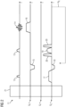
- FIG. 2 shows a TSE measurement sequence diagram 11.
- the turbo spin echo sequence is used to acquire measurement signals for phase correction.
- the echo train with a number of N E echoes is acquired without phase encoding and thus without gradients in the phase encoding direction GP .
- ACQ denotes the axis for the radiofrequency pulses and the acquisition windows.
- the radiofrequency pulse 12 is typically a 90° pulse
- the refocusing pulse 13 is a 180° pulse. These generate the echo signals 14.
- a slice selection gradient 17 is applied simultaneously with the radiofrequency pulse 12, followed by a slice rephasing gradient 18.
- the slice rephasing gradient 18 typically has half the gradient moment compared to the slice selection gradient 17.
- the slice selection gradient 19 is applied. This gradient is surrounded by two spoiler gradients.
- the spoiler gradients 20 serve to destroy signal components that may arise due to imperfections in the refocusing pulse 13.
- a preparation module 21 can optionally be used before the high-frequency pulse 12.
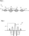
- FIG 3 shows an echo train 22, as it is connected to the TSE sequence Figure 2 can be obtained.
- the echo train 22 comprises, purely as an example, four echo signals 14a, 14b, 14c and 14d.
- the signal intensity or amplitude I max_A of the first echo signal 14a is indicated by arrow 23, and the signal amplitude I max_ of the last echo signal 14d is indicated by arrow 26.
- Arrows 24 and 25 indicate the signal amplitudes of the echo signals 14b and 14c.
- Arrow 24 indicates the signal amplitude I max_M , since this is, by definition, the largest signal amplitude in the echo train 22.
- ⁇ ⁇ I max _ M + 1 / 2 I max _ A + I max _ B .
- Figure 4 shows the echo signal 14b enlarged. This is intended to display several reference values derived from an echo signal.
- the maximum amplitude I max of the echo signal 14b can be used.
- the area of the echo signal component 27 can also be considered.
- other signal components such as signal components 28 and 29 can also be included.
- the integral of a portion of the echo signal 14b can be used.
- the reference value of the echo signals 14a, 14b, 14c and 14d can be freely selected per se, but must be selected the same for all echo signals 14a, 14b, 14c and 14d.
- the Figures 5 and 6 show echo signals 30 and 31.
- the echo signal 30 was recorded with coil 5 and the echo signal 31 with coil 6.
- the echo signals can then calculated to form a total signal as given in formula (7):
- I getician SQRT I max _ coil _ 4 2 + I max _ coil _ 5 2 + I max _ coil _ 6 2 + I max _ coil _ 7 2
- an echo train 22 can also be measured with each coil 4, 5, 6, and 7, and a reference amplitude can be determined for each coil analogous to equation (4). This reference amplitude can then be considered in equation (7).
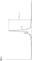
- Figure 7 shows an echo signal 14e, which is comparable in terms of recording to echo signal 14b.
- the preparation module 21 was applied before generating echo signal 14e. This reduced the signal amplitude I max , represented by arrow 32.
- the regularization parameter ⁇ can be determined as given in equation (9).
- Figure 8 shows part of a control panel 33. This contains a dropdown menu 34 for modifying the regularization parameter ⁇ . Depending on which of the selection fields 35, 36, or 37 is selected, the regularization parameter ⁇ is modified according to one of the equations (11) to (13).
- a slider 38 may also be provided for making a basic setting of the regularization parameter ⁇ .
Landscapes
- Physics & Mathematics (AREA)
- Engineering & Computer Science (AREA)
- General Physics & Mathematics (AREA)
- High Energy & Nuclear Physics (AREA)
- Health & Medical Sciences (AREA)
- General Health & Medical Sciences (AREA)
- Nuclear Medicine, Radiotherapy & Molecular Imaging (AREA)
- Radiology & Medical Imaging (AREA)
- Signal Processing (AREA)
- Condensed Matter Physics & Semiconductors (AREA)
- Artificial Intelligence (AREA)
- Computer Vision & Pattern Recognition (AREA)
- Theoretical Computer Science (AREA)
- Magnetic Resonance Imaging Apparatus (AREA)
Claims (15)
- Procédé mis en œuvre par ordinateur de production d'un ensemble de données d'image par résonance magnétique, comprenant les stades :- on se procure un ensemble de données brutes, l'ensemble de données brutes ayant été enregistré d'une manière sous-échantillonnée dans le temps et/ou dans l'espace,- on se procure des signaux de mesure d'une mesure de correction de phase,- détermination automatisée d'un paramètre (λ) de régularisation, et- production d'un ensemble de données d'image à partir de l'ensemble de données brutes en utilisant le paramètre (λ) de régularisation dans un procédé compressed-sensing,
caractérisé en ce que l'- on détermine le paramètre (λ) de régularisation à partir d'au moins deux signaux (14a, 14b, 14c, 14d, 14e) d'écho dans lequel
on utilise les signaux d'écho des signaux de mesure de la mesure de correction de phase,- l'enregistrement de l'ensemble de données brutes et la mesure de correction de phase sont effectués à l'aide d'une séquence TSE. - Procédé suivant la revendication 1, caractérisé en ce que l'on a enregistré les signaux (14a, 14b, 14c, 14d, 14e) d'écho dans un train (22) d'échos.
- Procédé suivant l'une des revendications 1 ou 2, caractérisé en ce que pour la détermination du paramètre (λ) de régularisation, on utilise l'amplitude (Imax_M, Imax_A, Imax_B) maximum de signal des signaux (14a, 14b, 14c, 14d, 14e) d'écho.
- Procédé suivant l'une des revendications précédentes, caractérisé en ce que l'on a enregistré les signaux (14a, 14b, 14c, 14d, 14e) d'écho avec au moins deux bobines (4, 5, 6, 7) différentes.
- Procédé suivant l'une des revendications précédentes, caractérisé en ce que l'on détermine le paramètre (λ) de régularisation par une addition d'amplitudes (Imax_M, Imax_A, Imax_B) de signal.
- Procédé suivant l'une des revendications précédentes, caractérisé en ce que l'on détermine le paramètre (λ) de régularisation par une division de deux amplitudes (Iohne, Imit) de signal.
- Procédé suivant l'une des revendications précédentes, caractérisé en ce que l'on a enregistré au moins l'un des signaux (14e) d'écho, notamment exactement un, en utilisant un module (21) de préparation.
- Procédé suivant l'une des revendications précédentes, caractérisé en ce que l'on détermine le paramètre (λ) de régularisation en formant une moyenne arithmétique d'amplitudes (Imax_A, Imax_B) de signal.
- Procédé suivant l'une des revendications précédentes, caractérisé en ce que l'on détermine le paramètre (λ) de régularisation en formant une moyenne quadratique d'amplitudes (Imax_coil_1, Imax_coil_2, Imax_coil_n) de signal des signaux (14a, 14b, 14c, 14d, 14e) d'écho.
- Procédé suivant l'une des revendications précédentes, caractérisé en ce que l'on a enregistré sans codage de phase les signaux (14a, 14b, 14c, 14d, 14e) d'écho.
- Procédé suivant l'une des revendications précédentes, caractérisé en ce que le paramètre (λ) de régularisation peut être modifié par des prescriptions de reconstruction pouvant être sélectionnées dans des champs (35, 36, 37) de sélection.
- Procédé suivant l'une des revendications précédentes, caractérisé en ce que le procédé compressed-sensing comprend une reconstruction itérative non linéaire.
- Produit (10) de programme d'ordinateur pour un dispositif (8) de commande pour la commande d'une unité de production de données, en particulier d'une unité de production d'images, d'une installation (1) de résonance magnétique, comprenant des instructions, qui lors de l'exécution du programme par le dispositif de commande, font que celui-ci exécute un procédé suivant l'une des revendications précédentes.
- Support (9) de données déchiffrable par ordinateur pour un dispositif (8) de commande pour la commande d'une unité de production de données, en particulier d'une unité de production d'images d'une installation (1) de résonance magnétique, sur lequel le produit de programme d'ordinateur suivant la revendication 13 est mis en mémoire.
- Installation (1) de résonance magnétique comprenant un dispositif (8) de commande, caractérisé en ce que le dispositif (8) de commande est constitué pour effectuer un procédé suivant l'une des revendications 1 à 12.
Priority Applications (2)
| Application Number | Priority Date | Filing Date | Title |
|---|---|---|---|
| EP18170822.3A EP3564695B1 (fr) | 2018-05-04 | 2018-05-04 | Procédé de génération d'un ensemble de données image par résonance magnétique, produit-programme informatique, support de données ainsi qu'installation de résonance magnétique |
| US16/403,463 US10977838B2 (en) | 2018-05-04 | 2019-05-03 | Method for generating a magnetic resonance image dataset, computer program product, data storage medium, and magnetic resonance system |
Applications Claiming Priority (1)
| Application Number | Priority Date | Filing Date | Title |
|---|---|---|---|
| EP18170822.3A EP3564695B1 (fr) | 2018-05-04 | 2018-05-04 | Procédé de génération d'un ensemble de données image par résonance magnétique, produit-programme informatique, support de données ainsi qu'installation de résonance magnétique |
Publications (3)
| Publication Number | Publication Date |
|---|---|
| EP3564695A1 EP3564695A1 (fr) | 2019-11-06 |
| EP3564695B1 true EP3564695B1 (fr) | 2025-06-25 |
| EP3564695C0 EP3564695C0 (fr) | 2025-06-25 |
Family
ID=62116721
Family Applications (1)
| Application Number | Title | Priority Date | Filing Date |
|---|---|---|---|
| EP18170822.3A Active EP3564695B1 (fr) | 2018-05-04 | 2018-05-04 | Procédé de génération d'un ensemble de données image par résonance magnétique, produit-programme informatique, support de données ainsi qu'installation de résonance magnétique |
Country Status (2)
| Country | Link |
|---|---|
| US (1) | US10977838B2 (fr) |
| EP (1) | EP3564695B1 (fr) |
Families Citing this family (1)
| Publication number | Priority date | Publication date | Assignee | Title |
|---|---|---|---|---|
| CN113420423A (zh) * | 2021-06-01 | 2021-09-21 | 郑州步始智能科技有限公司 | 频域中基于正则化法的从磁场垂直分量正演全张量的方法 |
Family Cites Families (26)
| Publication number | Priority date | Publication date | Assignee | Title |
|---|---|---|---|---|
| US7941204B1 (en) * | 2004-11-16 | 2011-05-10 | Yi Wang | Magnetic resonance imaging concepts |
| US7285954B2 (en) * | 2005-09-14 | 2007-10-23 | The United States Of America As Represented By The Secretary Of The Department Of Health And Human Services | Imaging and reconstruction of partial field of view in phase contrast MRI |
| US7535222B2 (en) * | 2007-01-02 | 2009-05-19 | The Board Of Trustees Of The Leland Stanford Junior University | MRI data acquisition using propeller k-space data acquisition |
| JP2009198778A (ja) | 2008-02-21 | 2009-09-03 | Fuji Xerox Co Ltd | 現像装置および画像形成装置 |
| US8089278B1 (en) * | 2008-04-11 | 2012-01-03 | The Regents Of The University Of California | Time-resolved contrast-enhanced magnetic resonance (MR) angiography |
| US8354844B2 (en) * | 2009-12-23 | 2013-01-15 | Universitaetsklinikum Freiburg | Method for data acquisition acceleration in magnetic resonance imaging (MRI) with N-dimensional spatial encoding using two or more receiver coil arrays and non-linear phase distributions |
| WO2011082225A1 (fr) * | 2010-01-04 | 2011-07-07 | Mayo Foundation For Medical Education And Research | Système et procédé d'angiographie par résonance magnétique à résolution temporelle et d'imagerie de perfusion combinées |
| US9465091B2 (en) * | 2010-01-04 | 2016-10-11 | Mayo Foundation For Medical Education And Research | System and method for random cartesian acquisition with projection reconstruction-like sampling |
| US8723517B2 (en) * | 2010-07-23 | 2014-05-13 | General Electric Company | Reduction of slice select artifacts in half pulse excitations used in ultrashort TE (UTE) imaging |
| US8618797B2 (en) * | 2010-07-23 | 2013-12-31 | General Electric Company | Composite spin locking pulse sequence and method of using the same |
| US8879852B2 (en) | 2010-11-10 | 2014-11-04 | Siemens Aktiengesellschaft | Non-contrast-enhanced 4D MRA using compressed sensing reconstruction |
| DE102011081411B4 (de) * | 2011-08-23 | 2013-04-11 | Friedrich-Alexander-Universität Erlangen-Nürnberg | Abtastmuster für iterative MR-Rekonstruktionsverfahren |
| US9507003B2 (en) * | 2012-09-19 | 2016-11-29 | Northshore University Healthsystem | System and method for imaging of vascular structures using non-contrast enhanced magnetic resonance imaging |
| US9396562B2 (en) | 2012-09-26 | 2016-07-19 | Siemens Aktiengesellschaft | MRI reconstruction with incoherent sampling and redundant haar wavelets |
| US9482732B2 (en) * | 2012-11-08 | 2016-11-01 | Nicolas Chesneau | MRI reconstruction with motion-dependent regularization |
| US9274197B2 (en) * | 2012-11-30 | 2016-03-01 | General Electric Company | Magnetic resonance imaging data sampling methods and systems |
| DE102013205868B4 (de) | 2013-04-03 | 2014-11-27 | Albert-Ludwigs-Universität Freiburg | Verfahren zum Zuordnen von K-Raum-Zeilen zu Echozügen und Verfahren zur Erfassung von MR-Daten sowie entsprechend ausgestaltete Magnetresonanzanlagen |
| DE102013213940B3 (de) | 2013-07-16 | 2015-01-08 | Siemens Aktiengesellschaft | Erfassung von MR-Daten mit unterschiedlicher Dichte |
| AU2015229128A1 (en) * | 2014-03-14 | 2016-09-22 | The General Hospital Corporation | System and method for free radical imaging |
| DE102014206395B4 (de) * | 2014-04-03 | 2016-10-20 | Siemens Healthcare Gmbh | Aufnahme und iterative Rekonstruktion einer Parameterkarte eines Zielbereichs |
| US10613176B2 (en) * | 2014-05-19 | 2020-04-07 | The United States Of America, As Represented By The Secretary, Department Of Health And Human Services | Magnetic resonance 2D relaxometry reconstruction using partial data |
| US20150346305A1 (en) * | 2014-05-28 | 2015-12-03 | General Electric Company | System and method for generating a magnetic resonance image |
| US10663549B2 (en) | 2014-11-25 | 2020-05-26 | Siemens Healthcare Gmbh | Compressed sensing reconstruction for multi-slice and multi-slab acquisitions |
| DE102015200353B4 (de) * | 2015-01-13 | 2017-11-16 | Siemens Healthcare Gmbh | Verfahren zur Aufnahme eines Magnetresonanzbilddatensatzes und Magnetresonanzeinrichtung |
| WO2019090447A1 (fr) * | 2017-11-10 | 2019-05-16 | Shenzhen United Imaging Healthcare Co., Ltd. | Système et procédé de reconstruction d'image |
| US10823806B2 (en) * | 2017-11-22 | 2020-11-03 | Siemens Healthcare Gmbh | Magnetic resonance imaging using dataset undersampling |
-
2018
- 2018-05-04 EP EP18170822.3A patent/EP3564695B1/fr active Active
-
2019
- 2019-05-03 US US16/403,463 patent/US10977838B2/en active Active
Also Published As
| Publication number | Publication date |
|---|---|
| EP3564695A1 (fr) | 2019-11-06 |
| EP3564695C0 (fr) | 2025-06-25 |
| US20190340794A1 (en) | 2019-11-07 |
| US10977838B2 (en) | 2021-04-13 |
Similar Documents
| Publication | Publication Date | Title |
|---|---|---|
| EP3296757B1 (fr) | Mesure d'empreinte digitale par résonance magnétique sans artéfact | |
| DE102013205785B4 (de) | Ermittlung einer Magnetresonanzsystem-Ansteuersequenz auf Basis einer reduzierten Anzahl an Feldverteilungskarten | |
| DE102011083406B4 (de) | Verfahren zur Auswahl eines Unterabtastungsschemas für eine MR-Bildgebung, Verfahren zur Magnetresonanz-Bildgebung und Magnetresonanzanlage | |
| DE102018113437A1 (de) | Mr-tomografie unter verwendung einer stack-of-stars-erfassung mit variablem kontrast | |
| EP3204785B1 (fr) | Procédé de réalisation d'une acquisition d'irm radiale ou hélicoïdale | |
| DE102017222359B4 (de) | Automatische Bestimmung von Korrekturfaktoren für eine Magnetresonanzanlage | |
| DE102013108467A1 (de) | Segment-Akquisition mit mehrfacher Anregung zur Bewegungskorrektur in der Magnetresonanztomographie | |
| EP3299836A1 (fr) | Correction locale de non-linéarités de gradients dans l'irm pondérée par la diffusion | |
| EP3828581B1 (fr) | Procédé de génération d'au moins un ensemble de données d'image et d'un ensemble de données d'image de référence, produit programme informatique ainsi qu'installation de résonance magnétique | |
| DE102016207314A1 (de) | Verfahren zur Anzeige von quantitativen Magnetresonanz-Bilddaten | |
| EP3828576B1 (fr) | Procédé de génération d'au moins un ensemble de données d'image et d'un ensemble de données d'image de référence, support de données, produit programme informatique ainsi qu'installation de résonance magnétique | |
| DE102013217336B3 (de) | Phasenkontrast-MR-Bildgebung mit Geschwindigkeitskodierung | |
| DE112019005169T5 (de) | Magnetresonanztomographie mit bewegungskompensierter bildrekonstruktion | |
| DE102018209584A1 (de) | Magnetresonanz-Fingerprinting-Verfahren | |
| DE102019219862B4 (de) | Kombinierte Bestimmung von T1 und eines Gewebeanteils | |
| DE102010003552B4 (de) | Verfahren zur Homogenisierung der Auflösung in Magnetresonanz-Tomographie-Aufnahmen unter Verwendung von nicht-linearen Kodierfeldern | |
| DE102014222495A1 (de) | Korrektur von Magnetresonanz-Bildaufnahmen mit Hilfe konvertierter Feldkarten | |
| EP3564695B1 (fr) | Procédé de génération d'un ensemble de données image par résonance magnétique, produit-programme informatique, support de données ainsi qu'installation de résonance magnétique | |
| DE102020209382A1 (de) | Verfahren zur Aufnahme von Messdaten mittels einer Magnetresonanzanlage mit einer Korrektur der verwendeten k-Raumtrajektorien | |
| EP3457159A1 (fr) | Procédé de prise d'empreintes par résonance magnétique amélioré | |
| EP3290940B1 (fr) | Reconstruction itérative d'images rm quantitatives | |
| EP3550318A1 (fr) | Procédé de génération d'une carte b0 utilisant l'empreinte par résonance magnétique | |
| EP3336572B1 (fr) | Détermination de paramètres de diffusion utilisant une comparaison des mesures à résonance magnétique avec des ensembles de données calculés | |
| DE102020202576B4 (de) | Verfahren zum Erzeugen eines Magnetresonanzbildes | |
| DE102008047218A1 (de) | Verfahren zur Erstellung von MR-Bildern mittels einer Magnetresonanzanlage sowie entsprechend ausgestaltete Magnetresonanzanlage |
Legal Events
| Date | Code | Title | Description |
|---|---|---|---|
| PUAI | Public reference made under article 153(3) epc to a published international application that has entered the european phase |
Free format text: ORIGINAL CODE: 0009012 |
|
| STAA | Information on the status of an ep patent application or granted ep patent |
Free format text: STATUS: REQUEST FOR EXAMINATION WAS MADE |
|
| 17P | Request for examination filed |
Effective date: 20190218 |
|
| AK | Designated contracting states |
Kind code of ref document: A1 Designated state(s): AL AT BE BG CH CY CZ DE DK EE ES FI FR GB GR HR HU IE IS IT LI LT LU LV MC MK MT NL NO PL PT RO RS SE SI SK SM TR |
|
| AX | Request for extension of the european patent |
Extension state: BA ME |
|
| STAA | Information on the status of an ep patent application or granted ep patent |
Free format text: STATUS: EXAMINATION IS IN PROGRESS |
|
| 17Q | First examination report despatched |
Effective date: 20210312 |
|
| RAP1 | Party data changed (applicant data changed or rights of an application transferred) |
Owner name: SIEMENS HEALTHINEERS AG |
|
| GRAP | Despatch of communication of intention to grant a patent |
Free format text: ORIGINAL CODE: EPIDOSNIGR1 |
|
| STAA | Information on the status of an ep patent application or granted ep patent |
Free format text: STATUS: GRANT OF PATENT IS INTENDED |
|
| INTG | Intention to grant announced |
Effective date: 20250107 |
|
| GRAS | Grant fee paid |
Free format text: ORIGINAL CODE: EPIDOSNIGR3 |
|
| GRAA | (expected) grant |
Free format text: ORIGINAL CODE: 0009210 |
|
| STAA | Information on the status of an ep patent application or granted ep patent |
Free format text: STATUS: THE PATENT HAS BEEN GRANTED |
|
| AK | Designated contracting states |
Kind code of ref document: B1 Designated state(s): AL AT BE BG CH CY CZ DE DK EE ES FI FR GB GR HR HU IE IS IT LI LT LU LV MC MK MT NL NO PL PT RO RS SE SI SK SM TR |
|
| REG | Reference to a national code |
Ref country code: GB Ref legal event code: FG4D Free format text: NOT ENGLISH |
|
| REG | Reference to a national code |
Ref country code: CH Ref legal event code: EP |
|
| REG | Reference to a national code |
Ref country code: CH Ref legal event code: EP |
|
| REG | Reference to a national code |
Ref country code: IE Ref legal event code: FG4D Free format text: LANGUAGE OF EP DOCUMENT: GERMAN |
|
| REG | Reference to a national code |
Ref country code: DE Ref legal event code: R096 Ref document number: 502018015893 Country of ref document: DE |
|
| U01 | Request for unitary effect filed |
Effective date: 20250703 |
|
| U07 | Unitary effect registered |
Designated state(s): AT BE BG DE DK EE FI FR IT LT LU LV MT NL PT RO SE SI Effective date: 20250710 |
|
| PG25 | Lapsed in a contracting state [announced via postgrant information from national office to epo] |
Ref country code: GR Free format text: LAPSE BECAUSE OF FAILURE TO SUBMIT A TRANSLATION OF THE DESCRIPTION OR TO PAY THE FEE WITHIN THE PRESCRIBED TIME-LIMIT Effective date: 20250926 Ref country code: NO Free format text: LAPSE BECAUSE OF FAILURE TO SUBMIT A TRANSLATION OF THE DESCRIPTION OR TO PAY THE FEE WITHIN THE PRESCRIBED TIME-LIMIT Effective date: 20250925 |
|
| PG25 | Lapsed in a contracting state [announced via postgrant information from national office to epo] |
Ref country code: HR Free format text: LAPSE BECAUSE OF FAILURE TO SUBMIT A TRANSLATION OF THE DESCRIPTION OR TO PAY THE FEE WITHIN THE PRESCRIBED TIME-LIMIT Effective date: 20250625 |
|
| PG25 | Lapsed in a contracting state [announced via postgrant information from national office to epo] |
Ref country code: RS Free format text: LAPSE BECAUSE OF FAILURE TO SUBMIT A TRANSLATION OF THE DESCRIPTION OR TO PAY THE FEE WITHIN THE PRESCRIBED TIME-LIMIT Effective date: 20250925 |
|
| PG25 | Lapsed in a contracting state [announced via postgrant information from national office to epo] |
Ref country code: IS Free format text: LAPSE BECAUSE OF FAILURE TO SUBMIT A TRANSLATION OF THE DESCRIPTION OR TO PAY THE FEE WITHIN THE PRESCRIBED TIME-LIMIT Effective date: 20251025 |
|
| PG25 | Lapsed in a contracting state [announced via postgrant information from national office to epo] |
Ref country code: SM Free format text: LAPSE BECAUSE OF FAILURE TO SUBMIT A TRANSLATION OF THE DESCRIPTION OR TO PAY THE FEE WITHIN THE PRESCRIBED TIME-LIMIT Effective date: 20250625 |
|
| PG25 | Lapsed in a contracting state [announced via postgrant information from national office to epo] |
Ref country code: CZ Free format text: LAPSE BECAUSE OF FAILURE TO SUBMIT A TRANSLATION OF THE DESCRIPTION OR TO PAY THE FEE WITHIN THE PRESCRIBED TIME-LIMIT Effective date: 20250625 |
|
| PG25 | Lapsed in a contracting state [announced via postgrant information from national office to epo] |
Ref country code: PL Free format text: LAPSE BECAUSE OF FAILURE TO SUBMIT A TRANSLATION OF THE DESCRIPTION OR TO PAY THE FEE WITHIN THE PRESCRIBED TIME-LIMIT Effective date: 20250625 |
|
| PG25 | Lapsed in a contracting state [announced via postgrant information from national office to epo] |
Ref country code: SK Free format text: LAPSE BECAUSE OF FAILURE TO SUBMIT A TRANSLATION OF THE DESCRIPTION OR TO PAY THE FEE WITHIN THE PRESCRIBED TIME-LIMIT Effective date: 20250625 |
|
| PG25 | Lapsed in a contracting state [announced via postgrant information from national office to epo] |
Ref country code: ES Free format text: LAPSE BECAUSE OF FAILURE TO SUBMIT A TRANSLATION OF THE DESCRIPTION OR TO PAY THE FEE WITHIN THE PRESCRIBED TIME-LIMIT Effective date: 20250625 |
|
| PLBE | No opposition filed within time limit |
Free format text: ORIGINAL CODE: 0009261 |
|
| STAA | Information on the status of an ep patent application or granted ep patent |
Free format text: STATUS: NO OPPOSITION FILED WITHIN TIME LIMIT |