EP3564901A1 - Informationsverarbeitungsvorrichtung, informationsverarbeitungsverfahren und programm - Google Patents
Informationsverarbeitungsvorrichtung, informationsverarbeitungsverfahren und programm Download PDFInfo
- Publication number
- EP3564901A1 EP3564901A1 EP17888366.6A EP17888366A EP3564901A1 EP 3564901 A1 EP3564901 A1 EP 3564901A1 EP 17888366 A EP17888366 A EP 17888366A EP 3564901 A1 EP3564901 A1 EP 3564901A1
- Authority
- EP
- European Patent Office
- Prior art keywords
- elastic modulus
- displacement
- observed
- external force
- distribution
- Prior art date
- Legal status (The legal status is an assumption and is not a legal conclusion. Google has not performed a legal analysis and makes no representation as to the accuracy of the status listed.)
- Withdrawn
Links
Images








Classifications
-
- A—HUMAN NECESSITIES
- A61—MEDICAL OR VETERINARY SCIENCE; HYGIENE
- A61B—DIAGNOSIS; SURGERY; IDENTIFICATION
- A61B5/00—Measuring for diagnostic purposes; Identification of persons
- A61B5/103—Measuring devices for testing the shape, pattern, colour, size or movement of the body or parts thereof, for diagnostic purposes
- A61B5/11—Measuring movement of the entire body or parts thereof, e.g. head or hand tremor or mobility of a limb
- A61B5/1104—Measuring movement of the entire body or parts thereof, e.g. head or hand tremor or mobility of a limb induced by stimuli or drugs
-
- A—HUMAN NECESSITIES
- A61—MEDICAL OR VETERINARY SCIENCE; HYGIENE
- A61B—DIAGNOSIS; SURGERY; IDENTIFICATION
- A61B1/00—Instruments for performing medical examinations of the interior of cavities or tubes of the body by visual or photographical inspection, e.g. endoscopes; Illuminating arrangements therefor
- A61B1/04—Instruments for performing medical examinations of the interior of cavities or tubes of the body by visual or photographical inspection, e.g. endoscopes; Illuminating arrangements therefor combined with photographic or television appliances
- A61B1/045—Control thereof
-
- A—HUMAN NECESSITIES
- A61—MEDICAL OR VETERINARY SCIENCE; HYGIENE
- A61B—DIAGNOSIS; SURGERY; IDENTIFICATION
- A61B5/00—Measuring for diagnostic purposes; Identification of persons
- A61B5/0059—Measuring for diagnostic purposes; Identification of persons using light, e.g. diagnosis by transillumination, diascopy, fluorescence
- A61B5/0077—Devices for viewing the surface of the body, e.g. camera, magnifying lens
-
- A—HUMAN NECESSITIES
- A61—MEDICAL OR VETERINARY SCIENCE; HYGIENE
- A61B—DIAGNOSIS; SURGERY; IDENTIFICATION
- A61B5/00—Measuring for diagnostic purposes; Identification of persons
- A61B5/103—Measuring devices for testing the shape, pattern, colour, size or movement of the body or parts thereof, for diagnostic purposes
- A61B5/11—Measuring movement of the entire body or parts thereof, e.g. head or hand tremor or mobility of a limb
- A61B5/1126—Measuring movement of the entire body or parts thereof, e.g. head or hand tremor or mobility of a limb using a particular sensing technique
- A61B5/1128—Measuring movement of the entire body or parts thereof, e.g. head or hand tremor or mobility of a limb using a particular sensing technique using image analysis
-
- A—HUMAN NECESSITIES
- A61—MEDICAL OR VETERINARY SCIENCE; HYGIENE
- A61B—DIAGNOSIS; SURGERY; IDENTIFICATION
- A61B8/00—Diagnosis using ultrasonic, sonic or infrasonic waves
- A61B8/08—Clinical applications
-
- G—PHYSICS
- G06—COMPUTING OR CALCULATING; COUNTING
- G06T—IMAGE DATA PROCESSING OR GENERATION, IN GENERAL
- G06T7/00—Image analysis
-
- G—PHYSICS
- G16—INFORMATION AND COMMUNICATION TECHNOLOGY [ICT] SPECIALLY ADAPTED FOR SPECIFIC APPLICATION FIELDS
- G16H—HEALTHCARE INFORMATICS, i.e. INFORMATION AND COMMUNICATION TECHNOLOGY [ICT] SPECIALLY ADAPTED FOR THE HANDLING OR PROCESSING OF MEDICAL OR HEALTHCARE DATA
- G16H30/00—ICT specially adapted for the handling or processing of medical images
- G16H30/40—ICT specially adapted for the handling or processing of medical images for processing medical images, e.g. editing
-
- G—PHYSICS
- G16—INFORMATION AND COMMUNICATION TECHNOLOGY [ICT] SPECIALLY ADAPTED FOR SPECIFIC APPLICATION FIELDS
- G16H—HEALTHCARE INFORMATICS, i.e. INFORMATION AND COMMUNICATION TECHNOLOGY [ICT] SPECIALLY ADAPTED FOR THE HANDLING OR PROCESSING OF MEDICAL OR HEALTHCARE DATA
- G16H50/00—ICT specially adapted for medical diagnosis, medical simulation or medical data mining; ICT specially adapted for detecting, monitoring or modelling epidemics or pandemics
- G16H50/50—ICT specially adapted for medical diagnosis, medical simulation or medical data mining; ICT specially adapted for detecting, monitoring or modelling epidemics or pandemics for simulation or modelling of medical disorders
Definitions
- the present invention relates to an information processing device, an information processing method and a program.
- elastography technique quantitatively and objectively evaluating elasticity information of a body tissue, such as an organ, and conducting image display of the distribution thereof has been put into practical use.
- the elastography technique include the magnetic resonance elastography (MRE) and the ultrasonic elastography.
- the MRE is an elastic modulus measurement method using the magnetic resonance imaging (MRI), which captures a measurement target in the state of being vibrated from the outside and images the vibrational wave propagating within the target substance.
- the ultrasonic elastography is one of methods which are represented by a method of utilizing a strain distribution in a tissue generated when an external pressure is applied to the measurement target, or a method of generating shear waves in a target tissue and utilizing a propagation rate thereof.
- a range of a region where the elasticity information can be acquired by the elastography technique is limited to a range in the vicinity of a local region where waves propagate (a surface portion of the target tissue) or a region where a pressure is applied.
- the invention described in claim 1 provides an information processing device including: a computation unit that determines, as an optimal solution which minimizes a difference between an observed displacement having been acquired from an image in which a portion of an elastic body has been captured and an estimated displacement of a partial region corresponding to an observation region from among estimated displacements calculated based on a three-dimensional model of the elastic body, a magnitude of an external force that acts upon an observed manipulation point and a distribution of an elastic modulus in the three-dimensional model.
- 1 represents a one-dimensional norm; and
- 2 represents a two-dimensional norm.
- the invention described in claim 3 provides an information processing device including: an acquisition unit that acquires an observed part of displacement from an image of an elastic body having been captured; an acceptance unit that accepts a manipulation point of an external force acting upon the elastic body; an estimation unit that estimates an estimated displacement of a three-dimensional model of the elastic body by using a distribution of an elastic modulus in the three-dimensional model and a magnitude of the external force as variables; and an optimization unit that minimizes a difference between the observed displacement and the estimated displacement corresponding to the observed displacement, so as to find an optimal solution that determines the magnitude of the external force and the distribution of the elastic modulus in the three-dimensional model.
- 1 represents a one-dimensional norm; and
- 2 represents a two-dimensional norm.
- the invention described in claim 5 provides the information processing device according to claim 1 or 3, further including: an expression unit that expresses the three-dimensional model based on the distribution of the elastic modulus determined as the optimal solution.
- the invention described in claim 6 provides the information processing device according to claim 1 or 3, wherein the image is a still image captured by a single image-capturing camera.
- the invention described in claim 7 provides the information processing device according to claim 1 or 3, wherein the optimal solution is determined as a value that minimizes a sum total of a sum of absolute values of changings from an initial value of the distribution of the elastic modulus and the difference.
- the invention described in claim 8 provides the information processing device according to claim 1 or 3, wherein, when plural pieces of information about the manipulation point are provided, the optimal solution is determined as a value that minimizes a sum total of the differences calculated for the individual manipulation points.
- the invention described in claim 9 provides the information processing device according to claim 1 or 3, wherein, when the plural external forces are applied to the manipulation point, the optimal solution is determined as a value that minimizes a sum total of the differences calculated for the individual external forces.
- the invention described in claim 10 provides the information processing device according to claim 1 or 3, wherein there are the plural manipulation points, and the external forces, which are different from one another, are applied to the respective manipulation points.
- the invention described in claim 11 provides the information processing device according to claim 1 or 3, wherein a spatial resolution that determines the optimal solution is gradually increased from a low level.
- the invention described in claim 12 provides the information processing device according to claim 1 or 3, wherein, when a magnitude of the external force that acts upon the manipulation point is given, the optimal solution is determined as the distribution of the elastic modulus that minimizes the difference.
- the invention described in claim 13 provides an information processing method including: a process that acquires an observed part of displacement from an image of an elastic body having been captured; a process that accepts a manipulation point of an external force acting upon the elastic body; a process that estimates an estimated displacement of a three-dimensional model of the elastic body by using a distribution of an elastic modulus in the three-dimensional model and a magnitude of the external force as variables; and a process that minimizes a difference between the observed displacement and the estimated displacement corresponding to the observed displacement, so as to find an optimal solution that determines the magnitude of the external force and the distribution of the elastic modulus in the three-dimensional model.
- the invention described in claim 14 provides a program causing a computer to execute: a process that acquires an observed part of displacement from an image of an elastic body having been captured; a process that accepts a manipulation point of an external force acting upon the elastic body; a process that estimates an estimated displacement of a three-dimensional model of the elastic body by using a distribution of an elastic modulus in the three-dimensional model and a magnitude of the external force as variables; and a process that minimizes a difference between the observed displacement and the estimated displacement corresponding to the observed displacement, so as to find an optimal solution that determines the magnitude of the external force and the distribution of the elastic modulus in the three-dimensional model.
- FIG. 1 is a diagram illustrating a concept image of an estimation method adopted in the exemplary embodiments to be described later.
- a case where the entirety of an elastic body 1 cannot be observed in other words, a case where there are observed parts and unobserved parts
- description will be given of a method of estimating a distribution of an elastic modulus in the entire elastic body by use of local displacement information in the observed part.
- the estimation processing is executed by using the fact that positional information of a manipulation point Pa of an external force F that deforms the elastic body 1 is observed.
- the positional information of the manipulation point Pa may be provided to the processing system before the estimation processing is started, and the position of the manipulation point Pa is arbitrary. Consequently, as shown in FIG. 1 , it is unnecessary that the position of the manipulation point Pa exists in the observed part.
- information providing a magnitude f of the external force F that acts upon the manipulation point Pa or positional information of a point where the elastic body 1 is fixed to the surroundings (a fixed point) Pf may be observed or unobserved.
- FIG. 1 to describe the observed part and the unobserved part, the state in which a part of the elastic body 1 is covered with a shield 2 is shown; however, this does not mean that a part of the elastic body 1 is necessarily covered with the shield 2.
- a part included in an observation field is the observed part
- a part not included in the observation field is the unobserved part. Consequently, a part which is an unobserved region of the elastic body 1 (for example, a reverse side or a back surface side) is an example of the unobserved part.
- the displacement in the observed part of the elastic body 1 is assumed to be identified for each part. In other words, it is assumed that the displacement in the elastic body 1 due to application of the external force F is provided to the processing system as observed information.
- the displacement is provided only to a surface region of the elastic body 1 in some cases, and is provided to the elastic body 1 including the inner regions thereof in other cases.
- the elastic modulus in each exemplary embodiment includes: Young's modulus E representing stiffness in pressing or pulling directions; a stiffness modulus G representing stiffness in a shear direction; Poisson's ratio v; a volume elastic modulus K; and the like, and, in the exemplary embodiments to be described later, the elastic modulus is used on the assumption that the elastic modulus is Young's modulus.
- the elastic body 1 refers to a substance having a property of, while generating strain (being deformed) by application of an external force F, returning to an original dimension when application of the external force F is stopped.
- an elastic body represented by approximately using Hooke's law such as, for example, various kinds of organs in tissues from a living body, is assumed.
- the case in which the distribution of the elastic modulus in the elastic body 1 is not uniform means that, for example, the elastic modulus of at least a part of the elastic body 1 is different from the elastic modulus of the surrounding parts.
- the information processing system 100 includes: an information processing device 10 that executes arithmetic processing for estimating the distribution of the elastic modulus in the elastic body 1 (refer to FIG. 1 ); at least one image-capturing camera 20 used for capturing images of the elastic body 1; a three-dimensional image data storage device 30 that stores three-dimensional image data (volume data) used for generating a mesh model of the elastic body 1; a display device 40 used for displaying the estimated distribution of the elastic modulus; and an input device 50 configured with a mouse, a pointing device and the like operated by a user.
- the information processing device 10 is a so-called computer and configured with: a CPU (central processing unit) 11 that executes programs; a ROM (read only memory) 12 that stores programs, such as BIOS (basic input/output system) or firmware, or data; a RAM (random access memory) 13 that provides programs with work areas; and a storage unit 14 that stores image data to be subjected to processing.
- the storage unit 14 is a storage device, such as a hard disk device or a semiconductor memory. The functions accomplished through execution of programs by the CPU 11 will be described later.
- the image-capturing camera 20 is an image-capturing device used for observation of the elastic body 1.
- the image-capturing camera 20 may be an image-capturing device suitable for observation of the elastic body 1.
- an infrared camera, an endoscopic camera, an ultrasonic imaging device, a photoacoustic imaging device or the like is used as the image-capturing camera 20.
- the information processing device 10 can identify the displacement in each region via the movement of the feature point or infrared marker existing on the surface of the elastic body 1.
- the information processing device 10 can identify the displacement in each region including the interiors of the elastic body 1.
- an imaging element of the endoscopic camera may be a CCD (Charge Coupled Device) or a CMOS (Complementary MOS).
- a single image-capturing camera 20 is used to output a still image in which the elastic body 1 has been captured from one direction.
- the three-dimensional image data storage device 30 is configured with a large-capacity hard disk device or the like that stores, as three-dimensional image data, an image reconfigured (a reconfiguration image) by accumulating pieces of tomographic image data acquired by taking tomography of the elastic body 1.
- the three-dimensional image data storage device 30 can, not only be directly connected to the information processing device 10, but also exist on a network as a server or a network storage.
- CT Computer Purted Tomography
- PET PET
- MRI Magnetic Resonance Imaging
- the display device 40 is configured with, for example, a liquid crystal display.
- the liquid crystal display is configured with a liquid crystal panel, a backlight, and so forth.
- the display device 40 may be an organic EL (Electroluminescence) display or the like.
- FIG. 3 is a diagram illustrating a functional configuration example accomplished through execution of computer programs by the CPU 11.
- the observed displacement acquisition unit 112 is a functional unit that compares the camera image before the external force F is applied to the manipulation point Pa with the camera image after the external force F is applied to the manipulation point Pa to acquire the observed displacement u o in each region appearing in the image.
- the observed displacement u o acquired in the observed displacement acquisition unit 112 is the displacement of each position identified in the camera image, and positional relationship thereof with voxels constituting the mesh model 200 is uncertain.
- the more pieces of image information are included in the three-dimensional image data or the mesh model 200 the higher the matching accuracy with the camera image becomes.
- the mesh model 200 is used for matching, by comparing the rendering image formed by rendering the surface information of the three-dimensional image data on the surface of the mesh model 200 with brightness information of the camera image, it is possible to associate the observed displacements u o with the vertexes of the mesh model 200 with high matching accuracy.
- the manipulation point acceptance unit 113 identifies the position of the accepted manipulation point Pa by the identification number of the vertex on the mesh model 200, and outputs thereof to the displacement estimation unit 114.
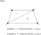
- FIG. 6 shows a two-dimensional mesh model. Needless to say, the information processing system 100 handles the three-dimensional mesh model 200.
- the triangular element I is defined by vertex numbers 1, 2 and 3
- the triangular element II is defined by vertex numbers 2, 3 and 4.
- f 1 f 2 f 3 f 4 K u 1 u 2 u 3 u 4
- K e V B T D T B
- V represents a volume of the triangular element.
- B matrix is determined from a shape function of an element
- D matrix is determined by the elastic modulus E and Poisson's ratio v.
- the D matrix can be expressed by the following equation (Equation 4).
- D E 1 + v 1 ⁇ 2 v 1 ⁇ v v v 0 0 0 v 1 ⁇ v v 0 0 0 v v 1 ⁇ v 0 0 0 0 0 1 ⁇ 2 ⁇ v 2 0 0 0 0 0 0 0 0 1 ⁇ 2 ⁇ v 2 0 0 0 0 0 0 0 1 ⁇ 2 ⁇ v 2 0 0 0 0 0 0 1 ⁇ 2 ⁇ v 2 0 0 0 0 0 0 1 ⁇ 2 ⁇ v 2
- Equation 4 the D matrix is a function of the elastic modulus E. Consequently, the element stiffness matrix K e is also expressed as the function of the elastic modulus E.
- the total stiffness matrix K is given by a sum of the element stiffness matrix K e of the triangular element I and the element stiffness matrix K e of the triangular element II.
- the total stiffness matrix K is given by a sum of the element stiffness matrix K e of the triangular element I constituted by the vertex numbers 1, 2 and 3 and the element stiffness matrix K e of the element stiffness matrix II constituted by the vertex numbers 2, 3 and 4.
- FIG. 7 is a diagram illustrating a concept of superimposition processing of the element stiffness matrix K e .
- FIG. 7 shows that the total stiffness matrix K is expressed by a sum of the element stiffness matrix K e of the element I and the element stiffness matrix K e of the element II.
- the element stiffness matrix K e is a function of the elastic modulus E
- the total stiffness matrix K expressed by the sum of them is also a function of the elastic modulus E.
- the camera image in the exemplary embodiment is an image in which a part of the elastic body 1 elastically deformed by the external force F has been captured, the manipulation point Pa thereof being observed but the magnitude f thereof being unobserved.
- Equation 2 unobserved parameters of Equation 2 are the distribution of the elastic modulus E (the total stiffness matrix K) and the magnitude f (the vector) of the external force F.
- the displacement estimation unit 114 sets arbitrary values for these respective unobserved parameters to calculate the estimated displacements u o '. Note that, in the first estimation of the estimated displacement u o ', the displacement estimation unit 114 provides an initial value to each of the distribution of the elastic modulus E (the total stiffness matrix K) and the magnitude f of the external force F, which are the unobserved parameters, to calculate the estimated displacement u o '.
- u o ' is the estimated displacement in the observed part
- u i ' is the estimated displacement in the unobserved part
- L o is the observed part of the inverse matrix component of the total stiffness matrix K expressed by the elastic modulus E
- L i is the unobserved part of the inverse matrix component of the total stiffness matrix K expressed by the elastic modulus E
- f o is the magnitude of the external force F that acts upon the vertex in the observed part
- f i is the magnitude of the external force F that acts upon the vertex in the unobserved part.
- Equation 5 Focusing on the estimated displacement u o ' of the observed part, Equation 5 can be expressed as the following equation (Equation 6).
- the magnitudes of the external forces F corresponding to the vertexes other than the manipulation point Pa can be expressed by 0 (zero).
- the displacement estimation unit 114 calculates the estimated displacement u o ' (including the initial value) from the component L o expressed by the elastic modulus E and the magnitude f of the external force F by use of Equation 6.
- the optimization unit 115 executes processing for solving the optimization problem that determines the unobserved parameter to minimize the difference between the estimated displacement u o ' and the observed displacement u o (that is, to provide the deformation most approximate to the observation result).
- E f argmin E , f ⁇ u o ⁇ u o ′
- 2 argmin E , f ⁇ u o ⁇ L o E f ⁇ 2
- E* means a set of E and f that minimizes the evaluation function J (E, f).
- the evaluation function J (E, f) is given by an L 2 norm of the difference between the estimated displacement u o ' and the observed displacement u o .
- the covariance matrix adaptation evolution strategy (CMA-ES) was used.
- any other known methods may be used. For example, a gradient method, Monte Carlo method, simulated annealing, or the like may be used.
- the expression unit 116 displays an image expressing, of the distribution of the elastic modulus E and the magnitude of the external force F identified as the optimal solution, the distribution of the elastic modulus E superimposed on the mesh model 200 on the display device 40 (refer to FIG. 2 ). Due to the distribution of the elastic modulus E being expressed in association with the mesh model 200, a user can visually recognize the distribution of the elastic modulus E of the elastic body 1 including the unobserved parts.
- the expression unit 116 expresses the differences in the elastic modulus E as the differences in colors or brightness. Moreover, the expression unit 116 may display the numerical value of the elastic modulus E corresponding to each part of the mesh model 200. Note that the expression unit 116 outputs the magnitude f of the external force F determined as the optimal solution as needed.
- the mesh model 200 corresponding to the elastic body 1 includes N vertexes, and description will be given of the effects of the number of observed vertexes on the estimation accuracy when the distribution of the elastic modulus E of the entire elastic body 1 is estimated by use of the observed displacements u o of the M vertexes (N > M).
- the method related to the exemplary embodiment was described as a program by use of Visual C/C++, and the generated program was executed by a general-purpose computer (OS: Windows 10 Pro, CPU: IntelCorei7-6700K, Memory: 16GB).
- OS Windows 10 Pro
- CPU IntelCorei7-6700K
- Memory 16GB
- the simulation was executed for the mesh model 200 in the shape of a rectangular parallelepiped (refer to FIG. 5 ).
- the mesh model 200 includes 99 vertexes in total, and the minimum element thereof is tetrahedron.
- FIG. 8 is a diagram depicting the distribution of the elastic modulus E used as a true value superimposed on the mesh model 200.
- the elastic modulus E of a part thereof is large (hard), and the elastic moduli E of the other parts have the same value.
- the node of the white dot represents that the node is positioned in the observed part
- the node of the black dot represents that the node is positioned in the unobserved part.
- the mesh model 200 shown in FIG. 8 represents a case in which, of the 40 cubic blocks, the elastic modulus E of the four cubic blocks, which are positioned at the seventh and eighth in the left row from the right end to the left direction (the -x direction), is as hard as 2.0 [MPa], and the elastic modulus E of the other parts is 1.0 [MPa].
- the mesh model 200 shown in FIG. 8 depicts the state in which the external force F of 10N was applied to the three vertexes at the lower right end part of the mesh model 200 of the elastic body 1 in the downward direction (in the -z axis direction) to deform the mesh model 200.
- the magnitude f of the external force F is also an unobserved parameter.
- the purpose of the simulation experiment is to evaluate the effects of the number of observed vertexes on the estimation accuracy of the elastic modulus E.
- FIG. 9 is a diagram illustrating a ratio of the number of observed vertexes in the mesh model 200.
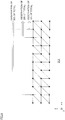
- FIG. 9 is a diagram observing the mesh model 200 from the lateral direction (on the x-z plane), where the mesh model 200 is divided into 10 small sections in the x axis direction.
- the case in which one small section is observed corresponds to the case in which 10% of the total is observed
- the case in which two small sections are observed corresponds to the case in which 20% of the total is observed.
- the case in which nine small sections are observed corresponds to the case in which 90% of the total is observed.
- the estimation accuracy of the elastic modulus E is affected by the number of dimensions of the estimation space.
- the number of dimensions is expressed by an estimated resolution of the elastic modulus E.
- the small number of dimensions of the estimation space means that the estimation is performed at a low resolution
- the large number of dimensions means that the estimation is performed at a high resolution.
- the number of dimensions of the estimation space represents the number of unit sections (blocks) into which one mesh model 200 is divided.
- FIG. 10 is a diagram illustrating a relationship between the number of estimation blocks N and a size of a unit section (block) for which the elastic modulus E is estimated.
- the larger the value of the number of estimation blocks N the smaller the size of the estimated unit section, the higher the spatial resolution becomes; therefore, the distribution of the elastic modulus E can be estimated with high definition.
- FIG. 11 is a diagram showing experimental results in the cases of the number of estimation blocks N is 10, 20, and 40.
- the vertical axis in FIG. 11 represents a root mean square error (RMSE) between the true elastic modulus E and the estimated elastic modulus E', and the horizontal axis represents the ratio of the number of observed vertexes accounting for the total (refer to FIG. 9 ).
- RMSE root mean square error
- the elastic modulus E can be estimated with high accuracy.
- the estimation accuracy depends upon the resolution in the estimation space and the ratio of the observed vertexes; if it is desired that the elastic modulus E in the elastic body 1 is estimated at high resolution, the area of the elastic body 1 to be captured by the image-capturing camera 20 is required to be widen, whereas, if it is desired that the elastic modulus E in the elastic body 1 is estimated at low resolution, the area of the elastic body 1 to be captured by the image-capturing camera 20 may be narrow.
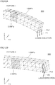
- FIG. 12 is a diagram illustrating observation conditions used in Exemplary embodiment 2.
- two sets of external force F and manipulation point Pa are prepared.
- FIG. 12A shows the first set of external force F1 and manipulation point Pa1 (pattern 1)
- FIG. 12B shows the second set of external force F2 and manipulation point Pa2 (pattern 2).
- the mesh model 200 shown in FIG. 12 depicts the cubic block having the elastic modulus E harder than the surroundings by shading.
- the first set (pattern 1) shown in FIG. 12A depicts deformation in the case where the first external force F1 is applied in the downward direction (in the -z axis direction) assuming three vertexes at the lower right end part of the mesh model 200 as the manipulation point Pa1.
- the second set (pattern 2) shown in FIG. 12B depicts deformation in the case where the second external force F2 is applied in the left direction (in the -y axis direction) assuming three vertexes positioned on the left side of the end face at the right end part of the mesh model 200 as the manipulation point Pa2.
- FIG. 12 the examples in which not only the manipulation point Pa, but also the acting direction of the external force F differs are shown; however, it may be possible that there are one manipulation point Pa and plural acting directions of the external force F, or there are two manipulation points Pa and one acting direction of the external force F.
- the information processing device 10 obtains the observed displacement u o for each pattern, and thereafter, determines, as the optimal solution, the magnitude f1 of the external force F1 and the magnitude f2 of the external force F2 to minimize the difference (u o -u o ') between the observed displacement u o and the estimated displacement u o ', and the distribution of the elastic modulus E in the entire region of the mesh model 200 for each pattern.
- the optimization unit 115 determines the unobserved parameter satisfying the following equation (Equation 9) as the optimal solution.
- E ⁇ argmin E , f J
- U o is a matrix arranging u 1o and u 2o in the column direction
- F is a matrix arranging f 1 and f 2 in the column direction.
- the two-dimensional norm in the equation of the third line is matrix norm, for example, Frobenius norm.
- FIG. 13 is a diagram showing experimental results in the cases of using one set (Exemplary embodiment 1) and two sets (Exemplary embodiment 2) of patterns for estimating the distribution of the elastic modulus E.
- the vertical axis in FIG. 13 represents a root mean square error (RMSE) between the true elastic modulus E and the estimated elastic modulus E', and the horizontal axis represents the ratio of the number of observed vertexes (refer to FIG. 9 ).
- RMSE root mean square error
- the number of sets defined by the manipulation point Pa and the magnitude f of the external force F is assumed to be "2"; however, the number of sets may be three or more.
- the estimation accuracy can be increased.
- the elastography method which is an example of the method for performing non-invasive evaluation of a strain image generated in an evaluation target (for example, an organ) by application of vibrations, such as ultrasonic waves
- the external force F made to be applied to the evaluation target temporally changes.
- sparsity means a property in which most of the elements are 0 (zero).
- the method can be adopted for an elastic body 1 that is known to have localization with partial stiffness or softness.
- the elastic modulus E in a healthy tissue is uniform, it is assumed that only part of a tumor region is hard (the elastic modulus E is high) as compared to the healthy tissue. Consequently, the sparsity can be utilized for estimating the distribution of the elastic modulus E in an organ.
- Equation 10 The second term in Equation 10 is the sparse term.
- Eo is a reference value of the elastic modulus applied to most of the vertexes. Consequently, the sparse term is an expression that determines a one-dimensional norm L 1 for a difference between the elastic modulus E estimated for each vertex and the reference value (that is, ⁇ E).
- the coefficient ⁇ was assumed to be 0.1.
- the norm is reduced. Consequently, the distribution of the elastic modulus E with a large norm in the sparse term is evaluated low.
- the value of the coefficient ⁇ is a specific example.
- FIG. 14 is a diagram showing experimental results in the cases of using one set of patterns (Exemplary embodiment 1) and two sets (Exemplary embodiment 2) of patterns for estimating the distribution of the elastic modulus E, and using sparsity of changes in the elastic modulus E (Exemplary embodiment 3) in addition to the case of two sets of patterns.
- the vertical axis in FIG. 14 represents a root mean square error (RMSE) between the true elastic modulus E and the estimated elastic modulus E', and the horizontal axis represents the ratio of the number of observed vertexes (refer to FIG. 9 ).
- RMSE root mean square error
- FIG. 15 is a diagram illustrating a relationship between the ratio of the number of observed vertexes and the observation accuracy in the exemplary embodiment.
- the vertical axis indicates the elastic modulus
- the horizontal axis indicates the block number.
- FIG. 15 represents the case in which the number of estimation blocks N is 40.
- the change of the true elastic modulus E is represented by a rectangular pulse
- the change of the estimated elastic modulus E is represented by a broken line.
- the information processing system 100 can be utilized for the medical support system that supports diagnosis or surgery by a doctor, the system 100 can be utilized in industrial fields other than the medical field, for purposes of observation or analysis, and for purposes of production and manufacturing.
- the image-capturing camera 20 may be an image-capturing unit capable of capturing the elastic body 1, which is the estimation target of the elastic modulus E, as a dynamic image.
- the above-described observed displacement u o may be acquired by use of a still image captured from the dynamic image that has been taken.
- the image capturing direction is not limited to one, but plural image capturing directions may be adopted.
- the information about the observed displacement u o can also be increased by using images capturing the deformation by the external force F from the plural directions, and thereby the estimation accuracy can be improved.
- the estimation processing is executed for the case in which the number of estimation blocks N is 10, to thereby obtain the estimation result in a short time and display thereof on the display device 40, and in the next estimation step, the number of estimation blocks N is increased to the predetermined value (for example, 20) and an update of execution of the estimation processing and display of the estimation result is repeated.
- the predetermined value for example, 20
Landscapes
- Health & Medical Sciences (AREA)
- Life Sciences & Earth Sciences (AREA)
- Engineering & Computer Science (AREA)
- Medical Informatics (AREA)
- Public Health (AREA)
- General Health & Medical Sciences (AREA)
- Biomedical Technology (AREA)
- Pathology (AREA)
- Surgery (AREA)
- Physics & Mathematics (AREA)
- Animal Behavior & Ethology (AREA)
- Molecular Biology (AREA)
- Heart & Thoracic Surgery (AREA)
- Biophysics (AREA)
- Veterinary Medicine (AREA)
- Nuclear Medicine, Radiotherapy & Molecular Imaging (AREA)
- Radiology & Medical Imaging (AREA)
- Epidemiology (AREA)
- Primary Health Care (AREA)
- Oral & Maxillofacial Surgery (AREA)
- Dentistry (AREA)
- Physiology (AREA)
- Computer Vision & Pattern Recognition (AREA)
- Databases & Information Systems (AREA)
- Data Mining & Analysis (AREA)
- Bioinformatics & Cheminformatics (AREA)
- Chemical & Material Sciences (AREA)
- Medicinal Chemistry (AREA)
- Optics & Photonics (AREA)
- General Physics & Mathematics (AREA)
- Theoretical Computer Science (AREA)
- Ultra Sonic Daignosis Equipment (AREA)
- Magnetic Resonance Imaging Apparatus (AREA)
- Image Analysis (AREA)
Applications Claiming Priority (2)
| Application Number | Priority Date | Filing Date | Title |
|---|---|---|---|
| JP2016254752 | 2016-12-28 | ||
| PCT/JP2017/044527 WO2018123559A1 (ja) | 2016-12-28 | 2017-12-12 | 情報処理装置、情報処理方法及びプログラム |
Publications (2)
| Publication Number | Publication Date |
|---|---|
| EP3564901A1 true EP3564901A1 (de) | 2019-11-06 |
| EP3564901A4 EP3564901A4 (de) | 2020-08-26 |
Family
ID=62707616
Family Applications (1)
| Application Number | Title | Priority Date | Filing Date |
|---|---|---|---|
| EP17888366.6A Withdrawn EP3564901A4 (de) | 2016-12-28 | 2017-12-12 | Informationsverarbeitungsvorrichtung, informationsverarbeitungsverfahren und programm |
Country Status (4)
| Country | Link |
|---|---|
| US (1) | US20200121225A1 (de) |
| EP (1) | EP3564901A4 (de) |
| JP (1) | JPWO2018123559A1 (de) |
| WO (1) | WO2018123559A1 (de) |
Family Cites Families (3)
| Publication number | Priority date | Publication date | Assignee | Title |
|---|---|---|---|---|
| WO2006024014A2 (en) * | 2004-08-24 | 2006-03-02 | The General Hospital Corporation | Process, system and software arrangement for measuring a mechanical strain and elastic properties of a sample |
| US9636075B2 (en) * | 2012-08-06 | 2017-05-02 | The University Of North Carolina At Chapel Hill | Simulation-based estimation of elasticity parameters and use of same for non-invasive cancer detection and cancer staging |
| JP6362851B2 (ja) * | 2013-11-20 | 2018-07-25 | キヤノンメディカルシステムズ株式会社 | 血管解析装置、血管解析プログラム、及び血管解析装置の作動方法 |
-
2017
- 2017-12-12 WO PCT/JP2017/044527 patent/WO2018123559A1/ja not_active Ceased
- 2017-12-12 US US16/474,820 patent/US20200121225A1/en not_active Abandoned
- 2017-12-12 EP EP17888366.6A patent/EP3564901A4/de not_active Withdrawn
- 2017-12-12 JP JP2018559002A patent/JPWO2018123559A1/ja active Pending
Also Published As
| Publication number | Publication date |
|---|---|
| JPWO2018123559A1 (ja) | 2019-11-07 |
| WO2018123559A1 (ja) | 2018-07-05 |
| EP3564901A4 (de) | 2020-08-26 |
| US20200121225A1 (en) | 2020-04-23 |
Similar Documents
| Publication | Publication Date | Title |
|---|---|---|
| US11250601B2 (en) | Learning-assisted multi-modality dielectric imaging | |
| CN102622759B (zh) | 一种结合灰度与几何信息的医学图像配准方法 | |
| JP6541334B2 (ja) | 画像処理装置、画像処理方法、およびプログラム | |
| US20150216496A1 (en) | Simulation-based estimation of elasticity parameters and use of same for non-invasive cancer detection and cancer staging | |
| JP6821403B2 (ja) | 画像処理装置、画像処理方法、画像処理システム、及びプログラム。 | |
| JP2017512522A (ja) | 対象に固有の動きモデルを生成かつ使用する装置および方法 | |
| Somphone et al. | Fast myocardial motion and strain estimation in 3D cardiac ultrasound with sparse demons | |
| CN112967386A (zh) | 生物力学建模方法、装置、电子设备及存储介质 | |
| Visentin et al. | Iterative simulations to estimate the elastic properties from a series of MRI images followed by MRI-US validation | |
| Plantefeve et al. | Atlas-based transfer of boundary conditions for biomechanical simulation | |
| Zacharaki et al. | A comparative study of biomechanical simulators in deformable registration of brain tumor images | |
| Quarteroni | The role of statistics in the era of big data: A computational scientist’perspective | |
| JP2017000623A (ja) | 外力推定装置及び方法、並びにコンピュータプログラム | |
| Mazaheri et al. | Hybrid Pixel‐Based Method for Cardiac Ultrasound Fusion Based on Integration of PCA and DWT | |
| Ozkan et al. | Compliance boundary conditions for patient-specific deformation simulation using the finite element method | |
| Qin et al. | Mapping cardiac fiber orientations from high-resolution DTI to high-frequency 3D ultrasound | |
| Morita et al. | Model-based estimation of elastic moduli by local displacement observation of an elastic body | |
| Morita et al. | Elastic modulus estimation based on local displacement observation of elastic body | |
| Hoerig et al. | Cartesian neural network constitutive models for data-driven elasticity imaging | |
| EP3564901A1 (de) | Informationsverarbeitungsvorrichtung, informationsverarbeitungsverfahren und programm | |
| US11094104B2 (en) | Information processing device, information processing method and non-transitory computer readable medium | |
| Lu et al. | Reconstruction of elasticity: a stochastic model-based approach in ultrasound elastography | |
| Hu et al. | A comparison of the accuracy of statistical models of prostate motion trained using data from biomechanical simulations | |
| Miller et al. | Characterization of fibrotic liver tissue microstructure for predicting shear wave speed variability: a machine-learning-based computational study | |
| Ayari et al. | Analysis of regional deformation of the heart's left ventricle using invariant SPHARM descriptors |
Legal Events
| Date | Code | Title | Description |
|---|---|---|---|
| STAA | Information on the status of an ep patent application or granted ep patent |
Free format text: STATUS: THE INTERNATIONAL PUBLICATION HAS BEEN MADE |
|
| PUAI | Public reference made under article 153(3) epc to a published international application that has entered the european phase |
Free format text: ORIGINAL CODE: 0009012 |
|
| STAA | Information on the status of an ep patent application or granted ep patent |
Free format text: STATUS: REQUEST FOR EXAMINATION WAS MADE |
|
| 17P | Request for examination filed |
Effective date: 20190628 |
|
| AK | Designated contracting states |
Kind code of ref document: A1 Designated state(s): AL AT BE BG CH CY CZ DE DK EE ES FI FR GB GR HR HU IE IS IT LI LT LU LV MC MK MT NL NO PL PT RO RS SE SI SK SM TR |
|
| AX | Request for extension of the european patent |
Extension state: BA ME |
|
| DAV | Request for validation of the european patent (deleted) | ||
| DAX | Request for extension of the european patent (deleted) | ||
| A4 | Supplementary search report drawn up and despatched |
Effective date: 20200729 |
|
| RIC1 | Information provided on ipc code assigned before grant |
Ipc: G16H 50/50 20180101ALI20200723BHEP Ipc: A61B 8/08 20060101ALI20200723BHEP Ipc: G06T 7/00 20170101AFI20200723BHEP Ipc: G16H 30/40 20180101ALI20200723BHEP Ipc: A61B 1/045 20060101ALI20200723BHEP |
|
| STAA | Information on the status of an ep patent application or granted ep patent |
Free format text: STATUS: THE APPLICATION HAS BEEN WITHDRAWN |
|
| 18W | Application withdrawn |
Effective date: 20211228 |