EP3564933B1 - Plaque de masque emballée, procédé d'emballage et panneau d'affichage - Google Patents
Plaque de masque emballée, procédé d'emballage et panneau d'affichage Download PDFInfo
- Publication number
- EP3564933B1 EP3564933B1 EP18859516.9A EP18859516A EP3564933B1 EP 3564933 B1 EP3564933 B1 EP 3564933B1 EP 18859516 A EP18859516 A EP 18859516A EP 3564933 B1 EP3564933 B1 EP 3564933B1
- Authority
- EP
- European Patent Office
- Prior art keywords
- package
- adhesive line
- package adhesive
- width
- slit
- Prior art date
- Legal status (The legal status is an assumption and is not a legal conclusion. Google has not performed a legal analysis and makes no representation as to the accuracy of the status listed.)
- Active
Links
Images
Classifications
-
- G—PHYSICS
- G02—OPTICS
- G02F—OPTICAL DEVICES OR ARRANGEMENTS FOR THE CONTROL OF LIGHT BY MODIFICATION OF THE OPTICAL PROPERTIES OF THE MEDIA OF THE ELEMENTS INVOLVED THEREIN; NON-LINEAR OPTICS; FREQUENCY-CHANGING OF LIGHT; OPTICAL LOGIC ELEMENTS; OPTICAL ANALOGUE/DIGITAL CONVERTERS
- G02F1/00—Devices or arrangements for the control of the intensity, colour, phase, polarisation or direction of light arriving from an independent light source, e.g. switching, gating or modulating; Non-linear optics
- G02F1/01—Devices or arrangements for the control of the intensity, colour, phase, polarisation or direction of light arriving from an independent light source, e.g. switching, gating or modulating; Non-linear optics for the control of the intensity, phase, polarisation or colour
- G02F1/13—Devices or arrangements for the control of the intensity, colour, phase, polarisation or direction of light arriving from an independent light source, e.g. switching, gating or modulating; Non-linear optics for the control of the intensity, phase, polarisation or colour based on liquid crystals, e.g. single liquid crystal display cells
- G02F1/1303—Apparatus specially adapted to the manufacture of LCDs
-
- C—CHEMISTRY; METALLURGY
- C03—GLASS; MINERAL OR SLAG WOOL
- C03C—CHEMICAL COMPOSITION OF GLASSES, GLAZES OR VITREOUS ENAMELS; SURFACE TREATMENT OF GLASS; SURFACE TREATMENT OF FIBRES OR FILAMENTS MADE FROM GLASS, MINERALS OR SLAGS; JOINING GLASS TO GLASS OR OTHER MATERIALS
- C03C27/00—Joining pieces of glass to pieces of other inorganic material; Joining glass to glass other than by fusing
- C03C27/06—Joining glass to glass by processes other than fusing
- C03C27/10—Joining glass to glass by processes other than fusing with the aid of adhesive specially adapted for that purpose
-
- B—PERFORMING OPERATIONS; TRANSPORTING
- B32—LAYERED PRODUCTS
- B32B—LAYERED PRODUCTS, i.e. PRODUCTS BUILT-UP OF STRATA OF FLAT OR NON-FLAT, e.g. CELLULAR OR HONEYCOMB, FORM
- B32B17/00—Layered products essentially comprising sheet glass, or glass, slag, or like fibres
- B32B17/06—Layered products essentially comprising sheet glass, or glass, slag, or like fibres comprising glass as the main or only constituent of a layer, next to another layer of a specific material
-
- B—PERFORMING OPERATIONS; TRANSPORTING
- B32—LAYERED PRODUCTS
- B32B—LAYERED PRODUCTS, i.e. PRODUCTS BUILT-UP OF STRATA OF FLAT OR NON-FLAT, e.g. CELLULAR OR HONEYCOMB, FORM
- B32B7/00—Layered products characterised by the relation between layers; Layered products characterised by the relative orientation of features between layers, or by the relative values of a measurable parameter between layers, i.e. products comprising layers having different physical, chemical or physicochemical properties; Layered products characterised by the interconnection of layers
- B32B7/04—Interconnection of layers
- B32B7/12—Interconnection of layers using interposed adhesives or interposed materials with bonding properties
-
- G—PHYSICS
- G02—OPTICS
- G02F—OPTICAL DEVICES OR ARRANGEMENTS FOR THE CONTROL OF LIGHT BY MODIFICATION OF THE OPTICAL PROPERTIES OF THE MEDIA OF THE ELEMENTS INVOLVED THEREIN; NON-LINEAR OPTICS; FREQUENCY-CHANGING OF LIGHT; OPTICAL LOGIC ELEMENTS; OPTICAL ANALOGUE/DIGITAL CONVERTERS
- G02F1/00—Devices or arrangements for the control of the intensity, colour, phase, polarisation or direction of light arriving from an independent light source, e.g. switching, gating or modulating; Non-linear optics
- G02F1/01—Devices or arrangements for the control of the intensity, colour, phase, polarisation or direction of light arriving from an independent light source, e.g. switching, gating or modulating; Non-linear optics for the control of the intensity, phase, polarisation or colour
- G02F1/13—Devices or arrangements for the control of the intensity, colour, phase, polarisation or direction of light arriving from an independent light source, e.g. switching, gating or modulating; Non-linear optics for the control of the intensity, phase, polarisation or colour based on liquid crystals, e.g. single liquid crystal display cells
- G02F1/133—Constructional arrangements; Operation of liquid crystal cells; Circuit arrangements
- G02F1/1333—Constructional arrangements; Manufacturing methods
- G02F1/1339—Gaskets; Spacers; Sealing of cells
-
- G—PHYSICS
- G09—EDUCATION; CRYPTOGRAPHY; DISPLAY; ADVERTISING; SEALS
- G09F—DISPLAYING; ADVERTISING; SIGNS; LABELS OR NAME-PLATES; SEALS
- G09F9/00—Indicating arrangements for variable information in which the information is built-up on a support by selection or combination of individual elements
-
- H—ELECTRICITY
- H10—SEMICONDUCTOR DEVICES; ELECTRIC SOLID-STATE DEVICES NOT OTHERWISE PROVIDED FOR
- H10W—GENERIC PACKAGES, INTERCONNECTIONS, CONNECTORS OR OTHER CONSTRUCTIONAL DETAILS OF DEVICES COVERED BY CLASS H10
- H10W70/00—Package substrates; Interposers; Redistribution layers [RDL]
- H10W70/60—Insulating or insulated package substrates; Interposers; Redistribution layers
- H10W70/67—Insulating or insulated package substrates; Interposers; Redistribution layers characterised by their insulating layers or insulating parts
- H10W70/69—Insulating materials thereof
- H10W70/692—Ceramics or glasses
-
- B—PERFORMING OPERATIONS; TRANSPORTING
- B32—LAYERED PRODUCTS
- B32B—LAYERED PRODUCTS, i.e. PRODUCTS BUILT-UP OF STRATA OF FLAT OR NON-FLAT, e.g. CELLULAR OR HONEYCOMB, FORM
- B32B2457/00—Electrical equipment
- B32B2457/20—Displays, e.g. liquid crystal displays, plasma displays
-
- G—PHYSICS
- G02—OPTICS
- G02F—OPTICAL DEVICES OR ARRANGEMENTS FOR THE CONTROL OF LIGHT BY MODIFICATION OF THE OPTICAL PROPERTIES OF THE MEDIA OF THE ELEMENTS INVOLVED THEREIN; NON-LINEAR OPTICS; FREQUENCY-CHANGING OF LIGHT; OPTICAL LOGIC ELEMENTS; OPTICAL ANALOGUE/DIGITAL CONVERTERS
- G02F1/00—Devices or arrangements for the control of the intensity, colour, phase, polarisation or direction of light arriving from an independent light source, e.g. switching, gating or modulating; Non-linear optics
- G02F1/01—Devices or arrangements for the control of the intensity, colour, phase, polarisation or direction of light arriving from an independent light source, e.g. switching, gating or modulating; Non-linear optics for the control of the intensity, phase, polarisation or colour
- G02F1/13—Devices or arrangements for the control of the intensity, colour, phase, polarisation or direction of light arriving from an independent light source, e.g. switching, gating or modulating; Non-linear optics for the control of the intensity, phase, polarisation or colour based on liquid crystals, e.g. single liquid crystal display cells
- G02F1/133—Constructional arrangements; Operation of liquid crystal cells; Circuit arrangements
- G02F1/1333—Constructional arrangements; Manufacturing methods
- G02F1/1339—Gaskets; Spacers; Sealing of cells
- G02F1/13398—Spacer materials; Spacer properties
Definitions
- the present disclosure relates to the field of display device technologies, and more particularly relates to package masks, packaging methods, and display panels.
- a display panel is packaged with glass cement.
- the glass cement is coated/printed on an edge of one of the substrates according to a designed width to form a package adhesive line.
- the other substrate is packaged with the previous substrate by the package adhesive line to protect electronic components located between the two substrates.
- a height of the manufactured package adhesive line may deviate from a designed height, resulting in height deviations of the different package adhesive lines at four edges of the substrate, ultimately resulting in inconsistent heights of the package adhesive line at the four edges.
- an interval between the two substrates after packaging is inconsistent everywhere, which causes the display panel to have a Newton ring phenomenon and affects the quality of the product.
- US 2011/128493 A1 discloses a flat panel display including a first substrate, a second substrate, a light emitting region between the first and second substrates, and a sealant applied outside of the light emitting region, wherein the sealant has a rectangular shape and includes a first sealing part and a third sealing part opposite each other, and a second sealing part and a fourth sealing part opposite each other, the first, second, third, and fourth sealing parts being interconnected, and wherein the flat panel display includes a compensating part corresponding to at least one of the first, second, third, and fourth sealing parts on or in the first or second substrate.
- CN 106 494 066 discloses a making method of a silk-printing screen plate, comprising the following steps: providing a screen frame with a silk screen; coating the silk screen with screen paste, so that an adhesive application area and a non-adhesive-application area are obtained, and the non-adhesive-application area is covered with the screen paste; and coating one side of the silk screen obtained in the previous step with the screen paste, so that an uplifted area surrounding the adhesive application area is obtained, and the uplifted area is covered with the screen paste.
- US 2015/0131044 A1 discloses a display apparatus including a first substrate including a display area in which a plurality of pixels is disposed and a non-display area disposed adjacent to the display area, a second substrate which faces the first substrate, an image display layer between the first substrate and the second substrate, and a sealing member which is in the non-display area and attaches the first substrate and the second substrate.
- the first and second substrates have a curved surface in a first direction, and a flat surface in a second direction crossing the first direction A width of the sealing member extended in the first direction is greater than a width of the sealing member extended in the second direction.
- a package mask provided by the present disclosure includes a main body and a package slit group defined on the main body.
- the package slit group includes a first slit group extending along a first direction and a second slit group extending along a second direction.
- the first slit group and the second slit group are in communication with each other and are formed as an enclosed regular quadrangle.
- the first slit group includes at least two first slits each for manufacturing a first package adhesive line
- the second slit group includes at least two second slits each for manufacturing a second package adhesive line.
- a width of each of the first slits along the second direction is greater than a width of each of the second slits along the first direction.
- the first direction is the same as a printing direction in which a packaging material is printed onto the package mask.
- a ratio of the width of each of the first slits along the second direction to the width of each of the second slits along the first direction ranges from 1.15:1 to 1.25:1.
- the width of each of the first slits along the second direction ranges from 300 ⁇ m to 700 ⁇ m
- the width of each of the second slits along the first direction ranges from 240 ⁇ m to 609 ⁇ m.
- the present disclosure further provides a packaging method, which provides a package area by using the aforementioned mask.
- a used packaging material is glass cement.
- the present disclosure further provides a display panel, which is manufactured by using the aforementioned packaging method.
- a uniformity between a height of the first package adhesive line and a height of the second package adhesive line is less than 5%.
- the height of the first package adhesive line and the height of the second package adhesive line ranges from 5.2 ⁇ m to 5.7 ⁇ m.
- the aforementioned package mask includes the main body and the package slit group formed through the main body.
- the package slit group includes the first slit group extending along the first direction and the second slit group extending along the second direction.
- the first slit group includes at least two first slits
- the second slit group includes at least two second slits.
- the smaller amount of ink permeation can reduce a contact area with the material scraper, thereby reducing the pressure of the material scraper. Therefore, the uniformity between the height of the second package adhesive line formed according to the second slit and the height of the first package adhesive line formed according to the first slit can be improved, so that the interval between the two substrates of the display panel after packaging is equal everywhere, thereby avoiding the generation of Newton's ring and improving the quality of the display panel.
- a package method provided by the present disclosure comprises providing a package area by using a package mask of any one of the aforementioned embodiments, forming a first package adhesive line corresponding to the first slit group, and forming a second package adhesive line corresponding to the second slit group.
- the forming the first package adhesive line corresponding to the first slit group and the forming the second package adhesive line corresponding to the second slit group comprises providing a first substrate, disposing the package mask on the first substrate, coating a package adhesive in the first slit group and the second slit group, and operating a material scraper along the first direction on a surface of the mask to remove an excess package adhesive.
- a display panel manufactured by using the aforementioned packaging method is also provided by the present disclosure.
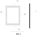
- FIG. 1 is a schematic view of a package mask and a traveling direction of a material scraper according to an embodiment of the present disclosure.
- display panels tend to produce Newton rings.
- an in-plane switching panel (IPS panel) is packaged by glass cement, and the glass cement is printed on four edges of the first substrate according to a designed width to form a package adhesive line.
- the designed width is determined by a width of a slit of the mask, so that four package adhesive lines are formed on the four edges of the first substrate, respectively, and the first substrate and the second substrate are packaged together by using the four glass adhesive lines.
- IPS panel in-plane switching panel
- the designed width is determined by a width of a slit of the mask, so that four package adhesive lines are formed on the four edges of the first substrate, respectively, and the first substrate and the second substrate are packaged together by using the four glass adhesive lines.
- a Newton's ring phenomenon is often generated between the first substrate and the second substrate, which affects the packaging effect of the display panel.
- the inventors of the present disclosure have found that, in the display panel manufactured by using the aforementioned scheme, the final heights of the four package adhesive lines are inconsistent, causing an interval between the first substrate and the second substrate after packaging to be different everywhere, resulting in a Newton's ring phenomenon.
- the present disclosure provides a package mask including a main body and a package slit group defined on the main body.
- the package slit group includes a first slit group extending along a first direction and a second slit group extending along a second direction.
- the first slit group includes at least two first slits 10
- the second slit group includes at least two second slits 20.
- a width of each of the first slits 10 along the second direction is greater than a width of each of the second slits 20 along the first direction.
- a first package adhesive line is provided corresponding to the first slit 10
- a second package adhesive line is provided corresponding to the second slit 20.
- the main body can be of a plate shape.
- the second slits 20 can be made to have a smaller amount of ink permeation with respect to the first slits 10. The smaller amount of ink permeation can reduce the contact area with the material scraper 3, thereby reducing the pressure of the material scraper 3.
- the uniformity between the height of the second package adhesive line formed according to the second slit 20 and the height of the first package adhesive line formed according to the first slit 10 can be improved, so that the interval between the two substrates of the display panel after packaging is equal everywhere, thereby avoiding the generation of Newton's ring and improving the quality of the display panel.
- the first slit group and the second slit group are in communication with each other.
- the plurality of first slits 10 included in the first slit group and the plurality of second slits 20 included in the second slit group intersect and are in communication with each other to form a mesh structure on the mask.
- a shape of the mesh structure is configured according to packaging requirements so as to form a mesh-connected package adhesive line via the mask.
- the first slit group and the second package slit group form an enclosed regular quadrangle so as to form an enclosed regular quadrangular adhesive line on the substrate.
- FIG. 1 a mask having an enclosed regular quadrangle of a printed structural unit is shown.
- a direction of an arrow indicates a printing direction of the material scraper 3.
- the printing direction is same as the first direction.
- the process of printing the glass cement on the substrate is introduced below.
- the mask is disposed on the substrate, the package adhesive is coated in the first slit group and the second slit group, and then the material scraper 3 is operated along the first direction on a surface of the mask, the package adhesive is pressed into the first slit 10 of the first slit group and the second slit 20 of the second slit group while excess package adhesive is scraped off. Therefore, an end-to-end package adhesive line is formed in the first slit group and the second slit group of the mask of one package structure unit.
- the first package adhesive line is manufactured according to the first slit 10
- the second package adhesive line is manufactured according to the second slit 20.
- the printing processes of the first package adhesive line and the second package adhesive line are compared.
- a contact area of the material scraper 3 in contact with the first slit 10 is less than a contact area of the material scraper 3 in contact with the second slit 20, the pressure of the package adhesive in the first slit 10 by the material scraper 3 is also relatively small, with respect to that in the second slit 20. Therefore, a value of the final width of the first package adhesive line deviates from the width of the first slit 10 along the second direction is less than that of the final width of the second package adhesive line deviates from the width of the second slit 20 along the first direction.
- a final height of the first package adhesive line is higher than a final height of the second package adhesive line.
- the contact area of the first slit 10 in contact with the material scraper 3 can be increased for compensating the difference of the contact area of the first slit 10 extending along the first direction in contact with the material scraper 3 from the contact area of the second slit 20 extending along the second direction in contact with the material scraper 3.
- the amount of ink permeation in the first slit 10 can be increased, that is, the amount of the package adhesive entering the first slit 10 is increased, thereby the pressure of the package adhesive entering the first slit 10 generated by the material scraper 3 is increased, so that the height of the first package adhesive line formed by the package adhesive in the first slit 10 is reduced, and finally the uniformity of the final height of the first package adhesive line and the final height of the second package adhesive line has been improved.
- a ratio of the width of each of the first slits 10 along the second direction to the width of each of the second slits 20 along the first direction ranges from 1.15:1 to 1.25:1.
- the present disclosure has found through research that the resulting final width has a certain relationship with the final height under the same width of the slit.
- the ratio of the width of each of the first slits 10 along the second direction to the width of each of the second slits 20 along the first direction is adjusted to be from 1.15:1 to 1.25:1, so as to finally offset the different influences of the printing direction on the package adhesive line according to the first slit group and the second slit group, so that the final width of the manufactured first package adhesive line is unified with the final width of the second package adhesive line, and the final height of the first package adhesive line is unified with the final height of the second package adhesive line. Therefore, the Newton's ring phenomenon occurs due to the inconsistency of the interval between the two substrates after the first package adhesive line and the second package adhesive line are packaged can be avoided.
- the width of each of the first slits 10 along the second direction ranges from 300 ⁇ m to 700 ⁇ m
- the width of each of the second slits 20 along the first direction ranges from 240 ⁇ m to 609 ⁇ m.
- the final width of the first package adhesive line and the second package adhesive line can be made within a suitable range after printing, and the packaging requirements of the display panel can be satisfied, and the packaging effect can be further improved.
- the width of the first slit 10 along the second direction and the width of the second slit 20 along the first direction are designed according to the product size and the size of the product frame, or are designed according to the packaging effect. Generally, the greater the width of the slit is, the greater the width of the corresponding sealant line is, and the better the sealing effect will be.
- a second aspect of the present disclosure further provides a packaging method, a package area is provided by the aforementioned mask, forming a first package adhesive line corresponding to a first slit group, and forming a second package adhesive line corresponding to a second slit group. Since the aforementioned mask has the above technical effects, the packaging method using the above mask for packaging should also have the same technical effect, and will not be described in detail herein.
- the packaging method includes the following steps of:
- the used packaging material is glass cement.
- the glass cement has a viscosity of 40,000 cps to 200,000 cps. By controlling the viscosity of the glass cement, the flowability of the glass cement is controlled to a certain extent to ensure that the final height of the package adhesive line is within the required range.
- a third aspect of the present disclosure further provides a display panel, which is manufactured by the aforementioned packaging method. Since the aforementioned packaging method has the above technical effects, the display panel manufactured by the above packaging method should also have the same technical effect, and will not be described in detail herein.
- a uniformity between a height of the first package adhesive line and a height of the second package adhesive line is less than 5%.
- the display panel adopts the above packaging method, and can significantly improve the uniformity of the height of the first package adhesive line and the second package adhesive line, and reduce the uniformity of the height of the first package adhesive line and the second package adhesive line to 5%.
- the interval between the two substrates of the display panel obtained by packaging is equal, and the Newton ring due to the uneven interval can be avoided, thereby improving the quality of the display panel.
- the height of the first package adhesive line and the height of the second package adhesive line are 5.2 ⁇ m to 5.7 ⁇ m. It can meet the packaging requirements of the display panel and further improve the packaging effect.
- a batch packaging production was carried out with a mask having a width of the first slit 10 along the second direction of 450 ⁇ m and a width of the second slit 20 along the first direction of 450 ⁇ m, and the obtained statistical data were shown in Table 1.
- a batch packaging production was carried out with a mask having a width of the first slit 10 along the second direction of 550 ⁇ m and a width of the second slit 20 along the first direction of 450 ⁇ m, and the obtained statistical data were shown in Table 2.
- Table 1 Statistical data for batch products of Comparative Example 1 Item Width Height/Depth First package adhesive line Second package adhesive line First package adhesive line Second package adhesive line Slit/ ⁇ m 450 450 5.80 5.80 Final value/ ⁇ m 464.5 506.3 5.80 5.32 Deviation value/ ⁇ m 14.5 56.3 0.35 0.13 Uniformity/% 2.15 3.28 4.71 7.82 Table 2 Statistical data for batch products of Example 1 Item Width Height/Depth First package adhesive line Second package adhesive line First package adhesive line Second package adhesive line Slit/ ⁇ m 550 450 5.80 5.80 Final value/ ⁇ m 564.0 504.3 5.35 5.21 Deviation value/ ⁇ m 14.0 54.3 0.1 0.24 Uniformity/% 1.35 4.72 5.38 5.71
- the slits refer to the first slit 10 and the second slit 20 corresponding to the first package adhesive line and the second package adhesive line, respectively.
- the final value is an average of the final width/height of the batch products.
- the deviation value is a difference between the final value minus a predetermined value.
- uniformity (maximum value - minimum value) / (maximum value + minimum value)
- the maximum value refers to a maximum value of the final width/height in the batch products
- the minimum value refers to a minimum value of the final width/height in the batch products.
- the final width of the first package adhesive line and the second package adhesive line are different, and the deviation tendency of the final widths is also different.
- the final heights of the first package adhesive line and the second package adhesive line are different, and the deviation tendency of the final heights is also different.
- the final widths of the first package adhesive line and the second package adhesive line have a certain relationship with the final heights thereof. The greater the final widths of the package adhesive line are, the lower the final heights are. Conversely, the less the final widths of the package adhesive line are, the higher the final heights are.
- the present disclosure derives the width of the first slit 10 along the second direction and the width of the second slit 20 along the first direction based on the analysis of the final width and the final height of the first package adhesive line and the second package adhesive line.
- Table 3 Calculation data of the cross-sectional area of the package adhesive line of the batch products Item Comparative example 1
- Example 1 First package adhesive line
- Second package adhesive line First package adhesive line
- Second package adhesive line Width of slit/ ⁇ m 450 450 550 450 Final width/ ⁇ m 464.5 506.3 564.0 504.3 Final height/ ⁇ m 5.80 5.32 5.35 5.31
- the widths of the slits refer to the width of the first slit 10 corresponding to the first package adhesive line along the second direction and the width of the second slit 20 corresponding to the second package adhesive line along the first direction, respectively.
- the cross-sectional area of the adhesive line is a longitudinal cross-sectional area of the first package adhesive line along the second direction or a longitudinal cross-sectional area of the second package adhesive line along the first direction.
- the actual longitudinal cross-sectional areas of the first package adhesive line of Comparative Example 1, the second package adhesive line of Comparative Example 1, the first package adhesive line of Example 1, and the second package adhesive line of Example 1 are assumed to be V 1 , V 2 , V 3 , and V 4 , respectively.
- the final widths thereof are L 1 , L 2 , L 3 , and L 4 , respectively, and the final heights thereof are H 1 , H 2 , H 3 , and H 4 , respectively.
- V 1 L 1 *H 1
- V 2 L 2 *H 2
- V 3 L 3 *H 3
- V 4 L 4 *H 4 .
- the second package adhesive line of Comparative Example 1 and the second package adhesive line of Embodiment 1 are both package adhesive lines extending along the second direction perpendicular to the printing direction.
- the degree of deviation of the final width thereof with respect to the width of the second slit 20 along the first direction is uniform, and the resulting final width is also close.
- H 1 H 3 .
- the first package adhesive line of Comparative Example 1 and the first package adhesive line of Embodiment 1 are both package adhesive lines extending along the first direction parallel to the printing direction.
- the degree of deviation of the final width thereof with respect to the width of the slit should also be same, and the resulting final width is also close.
- the widths of the slits corresponding to the mutually parallel package adhesive lines can be made same, so that the final widths and final heights of the two mutually parallel package adhesive lines are same.
- the first package adhesive line of Comparative Example 1 refers to the package adhesive line extending along the first direction parallel to the printing direction.
- the second package adhesive line refers to the package adhesive line extending along the second direction perpendicular to the printing direction.
- the width of the first slit 10 along the second direction corresponding to the above-mentioned first package adhesive line and the width of the second slit 20 along the first direction corresponding to the above-mentioned second package adhesive line are same. However, the final widths and final heights of the first package adhesive line and the second package adhesive line are different.
- the final width of the first package adhesive line is narrower than the final width of the second package adhesive line, and the final height of the first package adhesive line is higher than the final height of the second package adhesive line.
- the final heights of the first package adhesive line and the second package adhesive line are to be same, according to the concept of the present disclosure, it is required to increase the final width of the first package adhesive line, that is, the width of the first slit 10 corresponding to the first package adhesive line along the second direction needs to be relatively increased.
- the first package adhesive line of Example 1 is the package adhesive line extending along the first direction parallel to the printing direction
- the second package adhesive line of Example 1 is the package adhesive line extending along the second direction perpendicular to the printing direction.
- the width of the first slit 10 along the second direction and the width of the second slit 20 along the first direction respectively corresponding to the two are different.
- the final height of the resulting first package adhesive line is closer to that of the resulting second package adhesive line. Therefore, it is proved that if the final heights of the first package adhesive line and the second package adhesive line are to be same, the width of the corresponding first slit 10 along the second direction and the width of the second slit 20 along the first direction need to be adjusted accordingly.
- the present disclosure has found that the ratio of the width of the first slit 10 along the second direction to the width of the second slit 20 along the first direction is configured to be from 1.15:1 to 1.25:1, which can offset the different degrees of the pressure actions of the packaging material in the first slit 10 and the packaging material in the second slit 20 by the material scraper 3. Therefore, the uniformity of the final heights of the first package adhesive line and the second package adhesive line is high, preventing the generation of Newton's ring. In addition, the final height of the first package adhesive line is consistent with that of the second package adhesive line.
- the packaging effect would be improved, the sealing effect would be improved, and the water blocking and oxygen resistance effect would be improved.
- the ratio of the width of the first slit 10 along the second direction to the width of the second slit 20 along the first direction is configured to be from 1.15:1 to 1.25:1, so that the final heights of the first package adhesive line and the second package adhesive line are 5.2 ⁇ m to 5.7 ⁇ m, thereby satisfying the sealing requirement.
- the ratio of the width of the first slit 10 along the second direction to the width of the second slit 20 along the first direction is configured to be 1.2:1, so that the uniformity of the final heights of the first package adhesive line and the second package adhesive line can be further improved, and the final heights of the first package adhesive line and the second package adhesive line are controlled to be 5.3 ⁇ m to 5.6 ⁇ m.
- a batch packaging production was carried out with a mask, the mask has a first slit group and a second slit group which are formed as an enclosed regular quadrangle, a width of the first slit 10 along the second direction of 550 ⁇ m, and a width of the second slit 20 along the first direction of 450 ⁇ m.
- Table 4 Statistical data for batch products of Example 2 of the present disclosure Item Width Height/Depth First package adhesive line Second package adhesive line First package adhesive line Second package adhesive line Slit/ ⁇ m 550 450 5.45 5.45 Final value/ ⁇ m 574 493 5.37 5.43 Deviation value/ ⁇ m 24 43 0.08 0.02 Uniformity/% 1.27 3.31 4.09 3.81
- the slits refer to the first slit 10 and the second slit 20 corresponding to the first package adhesive line and the second package adhesive line, respectively.
- the final value refers to an average of the final width/height of the batch products.
- the deviation value refers to a difference between the final value minus a predetermined value.
- first and second are used for descriptive purposes only and are not to be construed as indicating or implying relative importance.
Landscapes
- Physics & Mathematics (AREA)
- Engineering & Computer Science (AREA)
- Chemical & Material Sciences (AREA)
- General Physics & Mathematics (AREA)
- Nonlinear Science (AREA)
- Theoretical Computer Science (AREA)
- Optics & Photonics (AREA)
- Crystallography & Structural Chemistry (AREA)
- Ceramic Engineering (AREA)
- Organic Chemistry (AREA)
- Chemical Kinetics & Catalysis (AREA)
- General Chemical & Material Sciences (AREA)
- Geochemistry & Mineralogy (AREA)
- Materials Engineering (AREA)
- Life Sciences & Earth Sciences (AREA)
- Mathematical Physics (AREA)
- Manufacturing & Machinery (AREA)
- Electroluminescent Light Sources (AREA)
- Liquid Crystal (AREA)
- Printing Plates And Materials Therefor (AREA)
- Devices For Indicating Variable Information By Combining Individual Elements (AREA)
- Packages (AREA)
Claims (11)
- Masque d'emballage, comprenant :un corps principal, etun groupe de fentes d'emballage défini sur le corps principal, le groupe de fentes d'emballage comprenant un premier groupe de fentes s'étendant le long d'un premier sens et un second groupe de fentes s'étendant le long d'un second sens, le premier groupe de fentes et le second groupe de fentes étant en communication l'un avec l'autre et sont formés en tant que quadrilatère régulier fermé, le premier groupe de fentes comprenant au moins deux premières fentes (10) chacune permettant de fabriquer une première ligne adhésive d'emballage, le second groupe de fentes comprenant au moins deux secondes fentes (20) chacune permettant de fabriquer une seconde ligne adhésive d'emballage, caractérisé en ce qu'une largeur de chacune des premières fentes (10) le long du second sens est supérieure à une largeur de chacune des secondes fentes (20) le long du premier sens, dans lequel le premier sens est le même qu'un sens d'impression dans lequel un matériau d'emballage est imprimé sur le masque d'emballage.
- Masque d'emballage selon la revendication 1, dans lequel un rapport entre la largeur de chacune des premières fentes (10) le long du second sens et la largeur de chacune des secondes fentes (20) le long du premier sens est compris entre 1,15:1 et 1,25:1.
- Masque d'emballage selon la revendication 2, dans lequel le rapport entre la largeur de chacune des premières fentes (10) le long du second sens et la largeur de chacune des secondes fentes (20) le long du premier sens est de 1,2:1.
- Masque d'emballage selon l'une quelconque des revendications 1 à 3, dans lequel la largeur de chacune des premières fentes (10) le long du second sens est comprise entre 300 µm et 700 µm, la largeur de chacune des secondes fentes (20) le long du premier sens est comprise entre 240 µm et 609 µm.
- Masque d'emballage selon l'une quelconque des revendications 1 à 4, dans lequel une hauteur de la première ligne adhésive d'emballage et une hauteur de la seconde ligne adhésive d'emballage sont comprises dans la plage allant de 5,2 µm à 5,7 µm.
- Masque d'emballage selon la revendication 5, dans lequel la hauteur de la première ligne adhésive d'emballage et la hauteur de la seconde ligne adhésive d'emballage sont comprises dans la plage allant de 5,3 µm à 5,6 µm.
- Procédé d'emballage, caractérisé par le fait qu'il comprend la fourniture d'une zone d'emballage en utilisant un masque d'emballage selon l'une quelconque des revendications 1 à 6, la formation d'une première ligne adhésive d'emballage correspondant au premier groupe de fentes, et la formation d'une seconde ligne adhésive d'emballage correspondant au second groupe de fentes ;
dans lequel la formation de la première ligne adhésive d'emballage correspondant au premier groupe de fentes et la formation de la seconde ligne adhésive d'emballage correspondant au second groupe de fentes comprend :la fourniture d'un premier substrat ;la disposition du masque d'emballage sur le premier substrat ;le revêtement d'un adhésif d'emballage dans le premier groupe de fentes et le second groupe de fentes ; etl'exploitation d'un racleur de matériau (3) le long du premier sens sur une surface du masque pour enlever un excès d'adhésif d'emballage. - Panneau d'affichage fabriqué en utilisant un procédé d'emballage selon la revendication 7.
- Panneau d'affichage selon la revendication 8, dans lequel une uniformité entre une hauteur d'une première ligne adhésive d'emballage et une hauteur d'une seconde ligne adhésive d'emballage est inférieure à 5 %.
- Panneau d'affichage selon la revendication 8 ou 9, dans lequel une hauteur de la première ligne adhésive d'emballage et une hauteur de la seconde ligne adhésive d'emballage sont comprises dans une plage allant de 5,2 µm à 5,7 µm.
- Panneau d'affichage selon la revendication 10, dans lequel la hauteur de la première ligne adhésive d'emballage et la hauteur de la seconde ligne adhésive d'emballage sont comprises dans une plage allant de 5,3 µm à 5,6 µm.
Applications Claiming Priority (2)
| Application Number | Priority Date | Filing Date | Title |
|---|---|---|---|
| CN201710874960.4A CN107742472B (zh) | 2017-09-25 | 2017-09-25 | 封装掩膜板、封装方法及显示面板 |
| PCT/CN2018/089083 WO2019056792A1 (fr) | 2017-09-25 | 2018-05-30 | Plaque de masque emballée, procédé d'emballage et panneau d'affichage |
Publications (3)
| Publication Number | Publication Date |
|---|---|
| EP3564933A1 EP3564933A1 (fr) | 2019-11-06 |
| EP3564933A4 EP3564933A4 (fr) | 2020-03-04 |
| EP3564933B1 true EP3564933B1 (fr) | 2025-06-11 |
Family
ID=61235303
Family Applications (1)
| Application Number | Title | Priority Date | Filing Date |
|---|---|---|---|
| EP18859516.9A Active EP3564933B1 (fr) | 2017-09-25 | 2018-05-30 | Plaque de masque emballée, procédé d'emballage et panneau d'affichage |
Country Status (7)
| Country | Link |
|---|---|
| US (1) | US20190322580A1 (fr) |
| EP (1) | EP3564933B1 (fr) |
| JP (1) | JP7038127B2 (fr) |
| KR (1) | KR102373535B1 (fr) |
| CN (1) | CN107742472B (fr) |
| TW (1) | TWI679623B (fr) |
| WO (1) | WO2019056792A1 (fr) |
Families Citing this family (3)
| Publication number | Priority date | Publication date | Assignee | Title |
|---|---|---|---|---|
| CN107742472B (zh) * | 2017-09-25 | 2021-03-26 | 昆山国显光电有限公司 | 封装掩膜板、封装方法及显示面板 |
| NL2024795B1 (en) | 2020-01-30 | 2021-09-10 | C1 Connections Holding B V | Assembly comprising a first and a second member and a connector, and a method of assembling such an assembly |
| CN118640834B (zh) * | 2024-08-13 | 2024-11-12 | 苏州希盟科技股份有限公司 | 一种透明胶线的截面积测量方法、装置、设备及介质 |
Citations (2)
| Publication number | Priority date | Publication date | Assignee | Title |
|---|---|---|---|---|
| US20150131044A1 (en) * | 2013-11-14 | 2015-05-14 | Samsung Display Co., Ltd. | Display apparatus |
| CN107088505A (zh) * | 2017-06-26 | 2017-08-25 | 京东方科技集团股份有限公司 | 一种封框胶刮刀及封框胶涂胶设备 |
Family Cites Families (39)
| Publication number | Priority date | Publication date | Assignee | Title |
|---|---|---|---|---|
| JP3007812B2 (ja) * | 1995-05-19 | 2000-02-07 | シャープ株式会社 | 液晶表示素子及びその製造方法 |
| JP3452467B2 (ja) * | 1997-08-25 | 2003-09-29 | シャープ株式会社 | 液晶表示装置の製造方法 |
| US6239855B1 (en) * | 1997-08-25 | 2001-05-29 | Sharp Kabushiki Kaisha | Method for producing a liquid crystal display panel having dummy seal particles arranged in at least two arrays |
| JP2001236891A (ja) | 2000-02-25 | 2001-08-31 | Matsushita Electric Ind Co Ltd | プラズマディスプレイパネル及びプラズマディスプレイパネルの製造方法 |
| US6873480B2 (en) * | 2001-11-08 | 2005-03-29 | Lightmaster Systems, Inc. | Method and apparatus for packaging optical elements |
| KR100710162B1 (ko) * | 2002-11-28 | 2007-04-20 | 엘지.필립스 엘시디 주식회사 | 액정표시장치의 실 패턴 형성방법 |
| KR100906567B1 (ko) * | 2002-12-31 | 2009-07-07 | 엘지디스플레이 주식회사 | 액정표시장치의 씰 패턴 스크린 인쇄장치 |
| JP4455166B2 (ja) * | 2004-05-28 | 2010-04-21 | アピックヤマダ株式会社 | リードフレーム |
| JP2007025516A (ja) | 2005-07-21 | 2007-02-01 | Sanyo Epson Imaging Devices Corp | 電気光学装置の製造方法、電気光学装置、シールマスク及びシール材印刷装置 |
| KR20080051756A (ko) * | 2006-12-06 | 2008-06-11 | 삼성에스디아이 주식회사 | 유기 발광 표시 장치 및 그 제조 방법 |
| JP2008221697A (ja) * | 2007-03-14 | 2008-09-25 | Mitsubishi Electric Corp | シール印刷用スクリーン版、シール印刷方法及びこれらを用いて製造された液晶パネル |
| KR100884477B1 (ko) * | 2007-08-08 | 2009-02-20 | 삼성모바일디스플레이주식회사 | 발광표시장치 및 그의 제조방법 |
| KR101084270B1 (ko) | 2009-12-01 | 2011-11-16 | 삼성모바일디스플레이주식회사 | 평판표시장치 |
| CN103930503B (zh) * | 2011-11-14 | 2017-12-12 | Lg化学株式会社 | 粘合膜 |
| CN102591134B (zh) * | 2012-03-15 | 2015-05-13 | 昆山维信诺显示技术有限公司 | 掩膜板及其制备方法 |
| TW201341192A (zh) | 2012-04-12 | 2013-10-16 | Wintek China Technology Ltd | 雙基板裝置及雙基板貼合方法 |
| TWI468818B (zh) * | 2012-08-07 | 2015-01-11 | Au Optronics Corp | 顯示裝置 |
| CN103293849A (zh) * | 2013-05-16 | 2013-09-11 | 深圳市华星光电技术有限公司 | 用于胶料涂布的掩膜板及其制作方法 |
| CN104252065A (zh) * | 2013-06-26 | 2014-12-31 | 北京京东方光电科技有限公司 | 一种显示基板及制作方法、显示装置 |
| CN103972256B (zh) * | 2014-05-20 | 2017-03-29 | 苏州晶方半导体科技股份有限公司 | 封装方法以及封装结构 |
| CN203849527U (zh) * | 2014-05-23 | 2014-09-24 | 京东方科技集团股份有限公司 | 一种基板上的边框胶线结构及基板 |
| KR102119698B1 (ko) * | 2014-09-05 | 2020-06-05 | 엘지디스플레이 주식회사 | 곡면 액정표시장치 |
| CN204116768U (zh) * | 2014-09-29 | 2015-01-21 | 厦门天马微电子有限公司 | 一种显示面板及其装置 |
| CN204167291U (zh) * | 2014-11-10 | 2015-02-18 | 京东方科技集团股份有限公司 | 用于玻璃胶涂布的掩膜板 |
| CN104651778B (zh) * | 2015-03-13 | 2016-04-27 | 京东方科技集团股份有限公司 | 一种金属掩膜板及其制作出的有机电致发光显示器件 |
| CN106299092A (zh) * | 2015-06-02 | 2017-01-04 | 上海和辉光电有限公司 | 具有封装对位功能的amoled面板及封装方法 |
| CN204833221U (zh) * | 2015-08-19 | 2015-12-02 | 合肥鑫晟光电科技有限公司 | 触摸屏及显示装置 |
| CN105093806B (zh) * | 2015-08-19 | 2019-12-27 | 京东方科技集团股份有限公司 | 一种uv掩膜板及其曝光方法 |
| CN105172324B (zh) * | 2015-09-24 | 2017-11-07 | 京东方科技集团股份有限公司 | 一种印刷网版及封框胶的印刷方法 |
| JP2017090528A (ja) | 2015-11-04 | 2017-05-25 | 株式会社ジャパンディスプレイ | 表示装置 |
| CN105404058B (zh) * | 2016-01-06 | 2019-01-22 | 京东方科技集团股份有限公司 | 液晶面板及其制作方法 |
| CN105549274A (zh) * | 2016-02-18 | 2016-05-04 | 武汉华星光电技术有限公司 | 改善液晶面板成盒工艺胶框固化率的方法及液晶面板 |
| JP2017181821A (ja) * | 2016-03-30 | 2017-10-05 | パナソニック液晶ディスプレイ株式会社 | 曲面ディスプレイを備えた車載デバイス |
| CN105932168B (zh) * | 2016-06-03 | 2019-04-30 | 京东方科技集团股份有限公司 | 制造oled面板的方法 |
| CN106494066B (zh) * | 2016-11-17 | 2019-01-18 | 信利半导体有限公司 | 一种丝印网板及其制作方法 |
| CN106505038B (zh) * | 2016-11-29 | 2019-09-17 | 深圳市华星光电技术有限公司 | Oled显示装置的制作方法 |
| CN206301119U (zh) * | 2017-01-03 | 2017-07-04 | 合肥京东方光电科技有限公司 | 一种背光模组及显示装置 |
| CN107507923B (zh) * | 2017-08-01 | 2019-12-03 | 京东方科技集团股份有限公司 | 一种丝网网版、封装方法、显示面板和显示装置 |
| CN107742472B (zh) * | 2017-09-25 | 2021-03-26 | 昆山国显光电有限公司 | 封装掩膜板、封装方法及显示面板 |
-
2017
- 2017-09-25 CN CN201710874960.4A patent/CN107742472B/zh active Active
-
2018
- 2018-05-30 WO PCT/CN2018/089083 patent/WO2019056792A1/fr not_active Ceased
- 2018-05-30 KR KR1020197022057A patent/KR102373535B1/ko active Active
- 2018-05-30 EP EP18859516.9A patent/EP3564933B1/fr active Active
- 2018-05-30 JP JP2019541221A patent/JP7038127B2/ja active Active
- 2018-05-30 US US16/342,195 patent/US20190322580A1/en not_active Abandoned
- 2018-06-15 TW TW107120709A patent/TWI679623B/zh active
Patent Citations (2)
| Publication number | Priority date | Publication date | Assignee | Title |
|---|---|---|---|---|
| US20150131044A1 (en) * | 2013-11-14 | 2015-05-14 | Samsung Display Co., Ltd. | Display apparatus |
| CN107088505A (zh) * | 2017-06-26 | 2017-08-25 | 京东方科技集团股份有限公司 | 一种封框胶刮刀及封框胶涂胶设备 |
Also Published As
| Publication number | Publication date |
|---|---|
| CN107742472B (zh) | 2021-03-26 |
| US20190322580A1 (en) | 2019-10-24 |
| TW201833882A (zh) | 2018-09-16 |
| EP3564933A4 (fr) | 2020-03-04 |
| EP3564933A1 (fr) | 2019-11-06 |
| KR102373535B1 (ko) | 2022-03-11 |
| CN107742472A (zh) | 2018-02-27 |
| JP2020509401A (ja) | 2020-03-26 |
| JP7038127B2 (ja) | 2022-03-17 |
| KR20190095482A (ko) | 2019-08-14 |
| TWI679623B (zh) | 2019-12-11 |
| WO2019056792A1 (fr) | 2019-03-28 |
Similar Documents
| Publication | Publication Date | Title |
|---|---|---|
| EP3564933B1 (fr) | Plaque de masque emballée, procédé d'emballage et panneau d'affichage | |
| CN104317110B (zh) | 一种转印版 | |
| CN105489786B (zh) | 阵列基板的封装结构及封装方法、显示面板 | |
| US9632366B2 (en) | Mask and method of manufacturing photoresist spacers with the mask | |
| WO2016074381A1 (fr) | Panneau à delo (oled) et procédé de fabrication, plaque de sérigraphie, et dispositif d'affichage | |
| WO2016074361A1 (fr) | Plaque de masque pour revêtement de ciment de verre et procédé de revêtement l'utilisant | |
| WO2016058323A1 (fr) | Substrat d'affichage et appareil d'affichage | |
| CN114222663B (zh) | 用于在丝网印刷方法中使用的丝网印版、丝网印刷装置和丝网印刷方法 | |
| CN105097670A (zh) | 一种母板及其制作方法 | |
| US10203563B2 (en) | Forming methods of liquid crystal layers, liquid crystal panels, and liquid crystal dripping devices | |
| CN109746140B (zh) | 封框胶掩膜板及制作方法、封框胶制作方法和显示面板 | |
| CN109765730B (zh) | 配向膜的制作方法及配向膜 | |
| TW201905551A (zh) | 顯示裝置 | |
| CN101738787A (zh) | 液晶显示器阵列基板及其制造方法 | |
| CN107584880A (zh) | 刮刀、包括刮刀的装置以及印刷玻璃胶的方法 | |
| US9785015B1 (en) | Display apparatus, and method of forming post spacer in display apparatus | |
| CN207818627U (zh) | 显示基板、显示面板和印版 | |
| CN109143656B (zh) | 显示装置 | |
| CN114721187A (zh) | 配向膜的制作方法及液晶显示面板 | |
| CN108958526B (zh) | 一种改善蚀刻痕迹的触摸屏制作方法 | |
| US7595506B2 (en) | Liquid crystal display device and display device | |
| US20050275786A1 (en) | Method for manufacturing liquid crystal display device | |
| US20110228208A1 (en) | Liquid crystal display panel, glass substrate, method for manufacturing liquid crystal display panel | |
| US20130126875A1 (en) | Liquid crystal display device | |
| JP2000010088A (ja) | カラー液晶表示パネル用マザー基板 |
Legal Events
| Date | Code | Title | Description |
|---|---|---|---|
| STAA | Information on the status of an ep patent application or granted ep patent |
Free format text: STATUS: THE INTERNATIONAL PUBLICATION HAS BEEN MADE |
|
| PUAI | Public reference made under article 153(3) epc to a published international application that has entered the european phase |
Free format text: ORIGINAL CODE: 0009012 |
|
| STAA | Information on the status of an ep patent application or granted ep patent |
Free format text: STATUS: REQUEST FOR EXAMINATION WAS MADE |
|
| 17P | Request for examination filed |
Effective date: 20190802 |
|
| AK | Designated contracting states |
Kind code of ref document: A1 Designated state(s): AL AT BE BG CH CY CZ DE DK EE ES FI FR GB GR HR HU IE IS IT LI LT LU LV MC MK MT NL NO PL PT RO RS SE SI SK SM TR |
|
| AX | Request for extension of the european patent |
Extension state: BA ME |
|
| A4 | Supplementary search report drawn up and despatched |
Effective date: 20200204 |
|
| RIC1 | Information provided on ipc code assigned before grant |
Ipc: G02F 1/1339 20060101ALI20200129BHEP Ipc: G09F 9/00 20060101AFI20200129BHEP Ipc: G02F 1/13 20060101ALI20200129BHEP |
|
| STAA | Information on the status of an ep patent application or granted ep patent |
Free format text: STATUS: EXAMINATION IS IN PROGRESS |
|
| 17Q | First examination report despatched |
Effective date: 20200504 |
|
| DAV | Request for validation of the european patent (deleted) | ||
| DAX | Request for extension of the european patent (deleted) | ||
| REG | Reference to a national code |
Ref country code: DE Ref legal event code: R079 Free format text: PREVIOUS MAIN CLASS: G09F0009000000 Ipc: G02F0001130000 Ref country code: DE Ref legal event code: R079 Ref document number: 602018082573 Country of ref document: DE Free format text: PREVIOUS MAIN CLASS: G09F0009000000 Ipc: G02F0001130000 |
|
| RIC1 | Information provided on ipc code assigned before grant |
Ipc: G09F 9/00 20060101ALI20210929BHEP Ipc: G02F 1/1339 20060101ALI20210929BHEP Ipc: G02F 1/13 20060101AFI20210929BHEP |
|
| GRAP | Despatch of communication of intention to grant a patent |
Free format text: ORIGINAL CODE: EPIDOSNIGR1 |
|
| STAA | Information on the status of an ep patent application or granted ep patent |
Free format text: STATUS: GRANT OF PATENT IS INTENDED |
|
| INTG | Intention to grant announced |
Effective date: 20250311 |
|
| GRAS | Grant fee paid |
Free format text: ORIGINAL CODE: EPIDOSNIGR3 |
|
| GRAA | (expected) grant |
Free format text: ORIGINAL CODE: 0009210 |
|
| STAA | Information on the status of an ep patent application or granted ep patent |
Free format text: STATUS: THE PATENT HAS BEEN GRANTED |
|
| AK | Designated contracting states |
Kind code of ref document: B1 Designated state(s): AL AT BE BG CH CY CZ DE DK EE ES FI FR GB GR HR HU IE IS IT LI LT LU LV MC MK MT NL NO PL PT RO RS SE SI SK SM TR |
|
| REG | Reference to a national code |
Ref country code: GB Ref legal event code: FG4D |
|
| REG | Reference to a national code |
Ref country code: CH Ref legal event code: EP |
|
| REG | Reference to a national code |
Ref country code: IE Ref legal event code: FG4D |
|
| REG | Reference to a national code |
Ref country code: DE Ref legal event code: R096 Ref document number: 602018082573 Country of ref document: DE |
|
| PG25 | Lapsed in a contracting state [announced via postgrant information from national office to epo] |
Ref country code: FI Free format text: LAPSE BECAUSE OF FAILURE TO SUBMIT A TRANSLATION OF THE DESCRIPTION OR TO PAY THE FEE WITHIN THE PRESCRIBED TIME-LIMIT Effective date: 20250611 Ref country code: ES Free format text: LAPSE BECAUSE OF FAILURE TO SUBMIT A TRANSLATION OF THE DESCRIPTION OR TO PAY THE FEE WITHIN THE PRESCRIBED TIME-LIMIT Effective date: 20250611 |
|
| REG | Reference to a national code |
Ref country code: LT Ref legal event code: MG9D |
|
| PG25 | Lapsed in a contracting state [announced via postgrant information from national office to epo] |
Ref country code: NO Free format text: LAPSE BECAUSE OF FAILURE TO SUBMIT A TRANSLATION OF THE DESCRIPTION OR TO PAY THE FEE WITHIN THE PRESCRIBED TIME-LIMIT Effective date: 20250911 Ref country code: GR Free format text: LAPSE BECAUSE OF FAILURE TO SUBMIT A TRANSLATION OF THE DESCRIPTION OR TO PAY THE FEE WITHIN THE PRESCRIBED TIME-LIMIT Effective date: 20250912 |
|
| REG | Reference to a national code |
Ref country code: NL Ref legal event code: MP Effective date: 20250611 |
|
| PG25 | Lapsed in a contracting state [announced via postgrant information from national office to epo] |
Ref country code: BG Free format text: LAPSE BECAUSE OF FAILURE TO SUBMIT A TRANSLATION OF THE DESCRIPTION OR TO PAY THE FEE WITHIN THE PRESCRIBED TIME-LIMIT Effective date: 20250611 |
|
| PG25 | Lapsed in a contracting state [announced via postgrant information from national office to epo] |
Ref country code: HR Free format text: LAPSE BECAUSE OF FAILURE TO SUBMIT A TRANSLATION OF THE DESCRIPTION OR TO PAY THE FEE WITHIN THE PRESCRIBED TIME-LIMIT Effective date: 20250611 |
|
| PG25 | Lapsed in a contracting state [announced via postgrant information from national office to epo] |
Ref country code: RS Free format text: LAPSE BECAUSE OF FAILURE TO SUBMIT A TRANSLATION OF THE DESCRIPTION OR TO PAY THE FEE WITHIN THE PRESCRIBED TIME-LIMIT Effective date: 20250911 |
|
| PG25 | Lapsed in a contracting state [announced via postgrant information from national office to epo] |
Ref country code: LV Free format text: LAPSE BECAUSE OF FAILURE TO SUBMIT A TRANSLATION OF THE DESCRIPTION OR TO PAY THE FEE WITHIN THE PRESCRIBED TIME-LIMIT Effective date: 20250611 |
|
| PG25 | Lapsed in a contracting state [announced via postgrant information from national office to epo] |
Ref country code: NL Free format text: LAPSE BECAUSE OF FAILURE TO SUBMIT A TRANSLATION OF THE DESCRIPTION OR TO PAY THE FEE WITHIN THE PRESCRIBED TIME-LIMIT Effective date: 20250611 |
|
| PG25 | Lapsed in a contracting state [announced via postgrant information from national office to epo] |
Ref country code: PT Free format text: LAPSE BECAUSE OF FAILURE TO SUBMIT A TRANSLATION OF THE DESCRIPTION OR TO PAY THE FEE WITHIN THE PRESCRIBED TIME-LIMIT Effective date: 20251013 |
|
| REG | Reference to a national code |
Ref country code: AT Ref legal event code: MK05 Ref document number: 1802721 Country of ref document: AT Kind code of ref document: T Effective date: 20250611 |
|
| PG25 | Lapsed in a contracting state [announced via postgrant information from national office to epo] |
Ref country code: IS Free format text: LAPSE BECAUSE OF FAILURE TO SUBMIT A TRANSLATION OF THE DESCRIPTION OR TO PAY THE FEE WITHIN THE PRESCRIBED TIME-LIMIT Effective date: 20251011 |
|
| PG25 | Lapsed in a contracting state [announced via postgrant information from national office to epo] |
Ref country code: AT Free format text: LAPSE BECAUSE OF FAILURE TO SUBMIT A TRANSLATION OF THE DESCRIPTION OR TO PAY THE FEE WITHIN THE PRESCRIBED TIME-LIMIT Effective date: 20250611 Ref country code: SM Free format text: LAPSE BECAUSE OF FAILURE TO SUBMIT A TRANSLATION OF THE DESCRIPTION OR TO PAY THE FEE WITHIN THE PRESCRIBED TIME-LIMIT Effective date: 20250611 |
|
| PG25 | Lapsed in a contracting state [announced via postgrant information from national office to epo] |
Ref country code: CZ Free format text: LAPSE BECAUSE OF FAILURE TO SUBMIT A TRANSLATION OF THE DESCRIPTION OR TO PAY THE FEE WITHIN THE PRESCRIBED TIME-LIMIT Effective date: 20250611 |
|
| PG25 | Lapsed in a contracting state [announced via postgrant information from national office to epo] |
Ref country code: PL Free format text: LAPSE BECAUSE OF FAILURE TO SUBMIT A TRANSLATION OF THE DESCRIPTION OR TO PAY THE FEE WITHIN THE PRESCRIBED TIME-LIMIT Effective date: 20250611 |
|
| PG25 | Lapsed in a contracting state [announced via postgrant information from national office to epo] |
Ref country code: EE Free format text: LAPSE BECAUSE OF FAILURE TO SUBMIT A TRANSLATION OF THE DESCRIPTION OR TO PAY THE FEE WITHIN THE PRESCRIBED TIME-LIMIT Effective date: 20250611 |
|
| PG25 | Lapsed in a contracting state [announced via postgrant information from national office to epo] |
Ref country code: SK Free format text: LAPSE BECAUSE OF FAILURE TO SUBMIT A TRANSLATION OF THE DESCRIPTION OR TO PAY THE FEE WITHIN THE PRESCRIBED TIME-LIMIT Effective date: 20250611 Ref country code: RO Free format text: LAPSE BECAUSE OF FAILURE TO SUBMIT A TRANSLATION OF THE DESCRIPTION OR TO PAY THE FEE WITHIN THE PRESCRIBED TIME-LIMIT Effective date: 20250611 |
|
| REG | Reference to a national code |
Ref country code: DE Ref legal event code: R097 Ref document number: 602018082573 Country of ref document: DE |
|
| PG25 | Lapsed in a contracting state [announced via postgrant information from national office to epo] |
Ref country code: DK Free format text: LAPSE BECAUSE OF FAILURE TO SUBMIT A TRANSLATION OF THE DESCRIPTION OR TO PAY THE FEE WITHIN THE PRESCRIBED TIME-LIMIT Effective date: 20250611 |
|
| PG25 | Lapsed in a contracting state [announced via postgrant information from national office to epo] |
Ref country code: IT Free format text: LAPSE BECAUSE OF FAILURE TO SUBMIT A TRANSLATION OF THE DESCRIPTION OR TO PAY THE FEE WITHIN THE PRESCRIBED TIME-LIMIT Effective date: 20250611 |
|
| PLBE | No opposition filed within time limit |
Free format text: ORIGINAL CODE: 0009261 |
|
| STAA | Information on the status of an ep patent application or granted ep patent |
Free format text: STATUS: NO OPPOSITION FILED WITHIN TIME LIMIT |
|
| REG | Reference to a national code |
Ref country code: CH Ref legal event code: L10 Free format text: ST27 STATUS EVENT CODE: U-0-0-L10-L00 (AS PROVIDED BY THE NATIONAL OFFICE) Effective date: 20260423 |