EP3565020B1 - Trennwand, zusammengesetzte batterie und wärmeübertragungsteuerungsverfahren für eine zusammengesetzte batterie - Google Patents
Trennwand, zusammengesetzte batterie und wärmeübertragungsteuerungsverfahren für eine zusammengesetzte batterie Download PDFInfo
- Publication number
- EP3565020B1 EP3565020B1 EP17886854.3A EP17886854A EP3565020B1 EP 3565020 B1 EP3565020 B1 EP 3565020B1 EP 17886854 A EP17886854 A EP 17886854A EP 3565020 B1 EP3565020 B1 EP 3565020B1
- Authority
- EP
- European Patent Office
- Prior art keywords
- partition member
- single cell
- cells
- cell
- thermal resistance
- Prior art date
- Legal status (The legal status is an assumption and is not a legal conclusion. Google has not performed a legal analysis and makes no representation as to the accuracy of the status listed.)
- Active
Links
Images



Classifications
-
- H—ELECTRICITY
- H01—ELECTRIC ELEMENTS
- H01M—PROCESSES OR MEANS, e.g. BATTERIES, FOR THE DIRECT CONVERSION OF CHEMICAL ENERGY INTO ELECTRICAL ENERGY
- H01M10/00—Secondary cells; Manufacture thereof
- H01M10/60—Heating or cooling; Temperature control
- H01M10/61—Types of temperature control
- H01M10/617—Types of temperature control for achieving uniformity or desired distribution of temperature
-
- H—ELECTRICITY
- H01—ELECTRIC ELEMENTS
- H01M—PROCESSES OR MEANS, e.g. BATTERIES, FOR THE DIRECT CONVERSION OF CHEMICAL ENERGY INTO ELECTRICAL ENERGY
- H01M50/00—Constructional details or processes of manufacture of the non-active parts of electrochemical cells other than fuel cells, e.g. hybrid cells
- H01M50/20—Mountings; Secondary casings or frames; Racks, modules or packs; Suspension devices; Shock absorbers; Transport or carrying devices; Holders
- H01M50/289—Mountings; Secondary casings or frames; Racks, modules or packs; Suspension devices; Shock absorbers; Transport or carrying devices; Holders characterised by spacing elements or positioning means within frames, racks or packs
-
- H—ELECTRICITY
- H01—ELECTRIC ELEMENTS
- H01M—PROCESSES OR MEANS, e.g. BATTERIES, FOR THE DIRECT CONVERSION OF CHEMICAL ENERGY INTO ELECTRICAL ENERGY
- H01M10/00—Secondary cells; Manufacture thereof
- H01M10/42—Methods or arrangements for servicing or maintenance of secondary cells or secondary half-cells
-
- H—ELECTRICITY
- H01—ELECTRIC ELEMENTS
- H01M—PROCESSES OR MEANS, e.g. BATTERIES, FOR THE DIRECT CONVERSION OF CHEMICAL ENERGY INTO ELECTRICAL ENERGY
- H01M10/00—Secondary cells; Manufacture thereof
- H01M10/60—Heating or cooling; Temperature control
- H01M10/62—Heating or cooling; Temperature control specially adapted for specific applications
- H01M10/625—Vehicles
-
- H—ELECTRICITY
- H01—ELECTRIC ELEMENTS
- H01M—PROCESSES OR MEANS, e.g. BATTERIES, FOR THE DIRECT CONVERSION OF CHEMICAL ENERGY INTO ELECTRICAL ENERGY
- H01M10/00—Secondary cells; Manufacture thereof
- H01M10/60—Heating or cooling; Temperature control
- H01M10/62—Heating or cooling; Temperature control specially adapted for specific applications
- H01M10/627—Stationary installations, e.g. power plant buffering or backup power supplies
-
- H—ELECTRICITY
- H01—ELECTRIC ELEMENTS
- H01M—PROCESSES OR MEANS, e.g. BATTERIES, FOR THE DIRECT CONVERSION OF CHEMICAL ENERGY INTO ELECTRICAL ENERGY
- H01M10/00—Secondary cells; Manufacture thereof
- H01M10/60—Heating or cooling; Temperature control
- H01M10/64—Heating or cooling; Temperature control characterised by the shape of the cells
- H01M10/647—Prismatic or flat cells, e.g. pouch cells
-
- H—ELECTRICITY
- H01—ELECTRIC ELEMENTS
- H01M—PROCESSES OR MEANS, e.g. BATTERIES, FOR THE DIRECT CONVERSION OF CHEMICAL ENERGY INTO ELECTRICAL ENERGY
- H01M10/00—Secondary cells; Manufacture thereof
- H01M10/60—Heating or cooling; Temperature control
- H01M10/65—Means for temperature control structurally associated with the cells
- H01M10/651—Means for temperature control structurally associated with the cells characterised by parameters specified by a numeric value or mathematical formula, e.g. ratios, sizes or concentrations
-
- H—ELECTRICITY
- H01—ELECTRIC ELEMENTS
- H01M—PROCESSES OR MEANS, e.g. BATTERIES, FOR THE DIRECT CONVERSION OF CHEMICAL ENERGY INTO ELECTRICAL ENERGY
- H01M10/00—Secondary cells; Manufacture thereof
- H01M10/60—Heating or cooling; Temperature control
- H01M10/65—Means for temperature control structurally associated with the cells
- H01M10/653—Means for temperature control structurally associated with the cells characterised by electrically insulating or thermally conductive materials
-
- H—ELECTRICITY
- H01—ELECTRIC ELEMENTS
- H01M—PROCESSES OR MEANS, e.g. BATTERIES, FOR THE DIRECT CONVERSION OF CHEMICAL ENERGY INTO ELECTRICAL ENERGY
- H01M10/00—Secondary cells; Manufacture thereof
- H01M10/60—Heating or cooling; Temperature control
- H01M10/65—Means for temperature control structurally associated with the cells
- H01M10/655—Solid structures for heat exchange or heat conduction
- H01M10/6554—Rods or plates
- H01M10/6555—Rods or plates arranged between the cells
-
- H—ELECTRICITY
- H01—ELECTRIC ELEMENTS
- H01M—PROCESSES OR MEANS, e.g. BATTERIES, FOR THE DIRECT CONVERSION OF CHEMICAL ENERGY INTO ELECTRICAL ENERGY
- H01M10/00—Secondary cells; Manufacture thereof
- H01M10/60—Heating or cooling; Temperature control
- H01M10/65—Means for temperature control structurally associated with the cells
- H01M10/658—Means for temperature control structurally associated with the cells by thermal insulation or shielding
-
- H—ELECTRICITY
- H01—ELECTRIC ELEMENTS
- H01M—PROCESSES OR MEANS, e.g. BATTERIES, FOR THE DIRECT CONVERSION OF CHEMICAL ENERGY INTO ELECTRICAL ENERGY
- H01M50/00—Constructional details or processes of manufacture of the non-active parts of electrochemical cells other than fuel cells, e.g. hybrid cells
- H01M50/20—Mountings; Secondary casings or frames; Racks, modules or packs; Suspension devices; Shock absorbers; Transport or carrying devices; Holders
-
- H—ELECTRICITY
- H01—ELECTRIC ELEMENTS
- H01M—PROCESSES OR MEANS, e.g. BATTERIES, FOR THE DIRECT CONVERSION OF CHEMICAL ENERGY INTO ELECTRICAL ENERGY
- H01M50/00—Constructional details or processes of manufacture of the non-active parts of electrochemical cells other than fuel cells, e.g. hybrid cells
- H01M50/20—Mountings; Secondary casings or frames; Racks, modules or packs; Suspension devices; Shock absorbers; Transport or carrying devices; Holders
- H01M50/204—Racks, modules or packs for multiple batteries or multiple cells
-
- H—ELECTRICITY
- H01—ELECTRIC ELEMENTS
- H01M—PROCESSES OR MEANS, e.g. BATTERIES, FOR THE DIRECT CONVERSION OF CHEMICAL ENERGY INTO ELECTRICAL ENERGY
- H01M50/00—Constructional details or processes of manufacture of the non-active parts of electrochemical cells other than fuel cells, e.g. hybrid cells
- H01M50/20—Mountings; Secondary casings or frames; Racks, modules or packs; Suspension devices; Shock absorbers; Transport or carrying devices; Holders
- H01M50/249—Mountings; Secondary casings or frames; Racks, modules or packs; Suspension devices; Shock absorbers; Transport or carrying devices; Holders specially adapted for aircraft or vehicles, e.g. cars or trains
-
- H—ELECTRICITY
- H01—ELECTRIC ELEMENTS
- H01M—PROCESSES OR MEANS, e.g. BATTERIES, FOR THE DIRECT CONVERSION OF CHEMICAL ENERGY INTO ELECTRICAL ENERGY
- H01M50/00—Constructional details or processes of manufacture of the non-active parts of electrochemical cells other than fuel cells, e.g. hybrid cells
- H01M50/20—Mountings; Secondary casings or frames; Racks, modules or packs; Suspension devices; Shock absorbers; Transport or carrying devices; Holders
- H01M50/289—Mountings; Secondary casings or frames; Racks, modules or packs; Suspension devices; Shock absorbers; Transport or carrying devices; Holders characterised by spacing elements or positioning means within frames, racks or packs
- H01M50/291—Mountings; Secondary casings or frames; Racks, modules or packs; Suspension devices; Shock absorbers; Transport or carrying devices; Holders characterised by spacing elements or positioning means within frames, racks or packs characterised by their shape
-
- H—ELECTRICITY
- H01—ELECTRIC ELEMENTS
- H01M—PROCESSES OR MEANS, e.g. BATTERIES, FOR THE DIRECT CONVERSION OF CHEMICAL ENERGY INTO ELECTRICAL ENERGY
- H01M50/00—Constructional details or processes of manufacture of the non-active parts of electrochemical cells other than fuel cells, e.g. hybrid cells
- H01M50/20—Mountings; Secondary casings or frames; Racks, modules or packs; Suspension devices; Shock absorbers; Transport or carrying devices; Holders
- H01M50/289—Mountings; Secondary casings or frames; Racks, modules or packs; Suspension devices; Shock absorbers; Transport or carrying devices; Holders characterised by spacing elements or positioning means within frames, racks or packs
- H01M50/293—Mountings; Secondary casings or frames; Racks, modules or packs; Suspension devices; Shock absorbers; Transport or carrying devices; Holders characterised by spacing elements or positioning means within frames, racks or packs characterised by the material
-
- H—ELECTRICITY
- H01—ELECTRIC ELEMENTS
- H01M—PROCESSES OR MEANS, e.g. BATTERIES, FOR THE DIRECT CONVERSION OF CHEMICAL ENERGY INTO ELECTRICAL ENERGY
- H01M2220/00—Batteries for particular applications
- H01M2220/10—Batteries in stationary systems, e.g. emergency power source in plant
-
- H—ELECTRICITY
- H01—ELECTRIC ELEMENTS
- H01M—PROCESSES OR MEANS, e.g. BATTERIES, FOR THE DIRECT CONVERSION OF CHEMICAL ENERGY INTO ELECTRICAL ENERGY
- H01M2220/00—Batteries for particular applications
- H01M2220/20—Batteries in motive systems, e.g. vehicle, ship, plane
-
- Y—GENERAL TAGGING OF NEW TECHNOLOGICAL DEVELOPMENTS; GENERAL TAGGING OF CROSS-SECTIONAL TECHNOLOGIES SPANNING OVER SEVERAL SECTIONS OF THE IPC; TECHNICAL SUBJECTS COVERED BY FORMER USPC CROSS-REFERENCE ART COLLECTIONS [XRACs] AND DIGESTS
- Y02—TECHNOLOGIES OR APPLICATIONS FOR MITIGATION OR ADAPTATION AGAINST CLIMATE CHANGE
- Y02E—REDUCTION OF GREENHOUSE GAS [GHG] EMISSIONS, RELATED TO ENERGY GENERATION, TRANSMISSION OR DISTRIBUTION
- Y02E60/00—Enabling technologies; Technologies with a potential or indirect contribution to GHG emissions mitigation
- Y02E60/10—Energy storage using batteries
-
- Y—GENERAL TAGGING OF NEW TECHNOLOGICAL DEVELOPMENTS; GENERAL TAGGING OF CROSS-SECTIONAL TECHNOLOGIES SPANNING OVER SEVERAL SECTIONS OF THE IPC; TECHNICAL SUBJECTS COVERED BY FORMER USPC CROSS-REFERENCE ART COLLECTIONS [XRACs] AND DIGESTS
- Y02—TECHNOLOGIES OR APPLICATIONS FOR MITIGATION OR ADAPTATION AGAINST CLIMATE CHANGE
- Y02T—CLIMATE CHANGE MITIGATION TECHNOLOGIES RELATED TO TRANSPORTATION
- Y02T10/00—Road transport of goods or passengers
- Y02T10/60—Other road transportation technologies with climate change mitigation effect
- Y02T10/70—Energy storage systems for electromobility, e.g. batteries
Definitions
- the present invention relates to a partition member, to an assembled battery and to a method for controlling heat transfer in an assembled battery.
- PTL 4 discloses a method wherein a partition member that is disposed between electric storage elements is configured to have a base material formed of a resin, and a foaming agent held in the base material and which undergoes thermal decomposition in response to a rise in temperature derived from generation of heat by the electric storage elements, so that transfer of heat from an abnormally heated battery cell to an adjacent battery cell is suppressed as a result.
- it is able to provide a partition member that allows controlling transfer of heat between single cells in an assembled battery having a plurality of single cells.
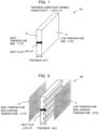
- the partition member according to the present invention is a partition member that separates single cells that make up an assembled battery.
- the partition member which separates single cells that make up an assembled battery, has two surfaces in the thickness direction, wherein when the average temperature of one of the two surfaces exceeds 180°C, a thermal resistance per unit area ( ⁇ 1 ) in the thickness direction satisfies Expression 1 below; and when the average temperatures of both of the two surface do not exceed 80°C, a thermal resistance per unit area ( ⁇ 2 ) in the thickness direction satisfies Expression 2 below.
- ⁇ 1 5.0 ⁇ 10 ⁇ 3 m 2 ⁇ K / W ⁇ 2 ⁇ 4.0 ⁇ 10 ⁇ 3 m 2 ⁇ K / W
- the combined thermal conductivity ( ⁇ ) of the composite member can be expressed as given by Expression (11) below, since the total cross-sectional area of the composite member is herein ⁇ A n .
- R d / ⁇ / ⁇ An
- the barycenter of the partition member to be checked is worked out.
- a perpendicular line is drawn from the barycenter to one face of the partition member, and the obtained intersection point is taken as a first point.
- Heating is then performed so that entire surface that encompasses the first point is heated to 160°C.
- the heating method is not particularly limited, so long as heating can be performed through control of the temperature so that the entire surface including a given first point is at 160°C to 300°C.
- the temperature of the surface including the first point is raised from 160°C to 300°C, on the basis of the first point and the second point.
- the thermal resistance ( ⁇ 1 ) is then worked out in accordance with the method described above, when the temperature of the entire system reaches a steady state, at temperatures of 160°C, 180°C, 210°C, 240°C, 270°C and 300°C.
- the cells 2 are each a lithium ion secondary battery cell provided for instance with a positive electrode and a negative electrode capable of storing and releasing lithium ions, and with an electrolyte.
- secondary batteries such as lithium ion all-solid-state battery cells, nickel-hydride battery cells, nickel cadmium battery cells and lead storage battery cells can be used.
- Cells 2 in a normal state will be referred to as “single cells maintaining a normal state", and cells 2 deviating from the normal state but not having reached an abnormal heating state will be referred to as “single cells deviating from the normal state”. Heat generated inside the cells 2 is transmitted to other cells 2 via various transmission paths.
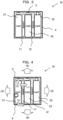
- Fig. 4 is a diagram illustrating an example of heat transfer paths in an assembled battery.
- the heat generated by the cell 21 is transmitted to other cells 22, 23 via: (1) the partition member 11 disposed between the cells, (2) the bus bars 3, and (3) the case 4 of the assembled battery 10 in contact with the cells 2; in addition, (4) the heat is also dissipated out of the case of the assembled battery 10.
- the upper limit of surface average temperature envisaged for an instance where cells 2 in contact with or in the vicinity of partition members 1 do not deviate from the normal state is set herein to 80°C.
- the boiling points of generic electrolyte solution components are 90°C or higher, as given in Table 1.
- Generic electrolyte solution components include for instance ethylene carbonate (EC), diethyl carbonate, dimethyl carbonate (DMC) and ethyl methyl carbonate (EMC). If the surface average temperature of the cells 2 is lower than 80°C there ensues thus no boiling of the generic electrolyte solution itself that makes up the cells 2.
- a means for controlling the thermal resistance per unit area ( ⁇ ) depending on the surface temperature of the partition members 1 will be explained next. Firstly a material A and a material B that make up the partition members 1 will be illustrated below.
- the thermal resistance per unit area ( ⁇ ) of the material B satisfies (Expression 2) above.
- the material B is for instance water, ethylene glycol or glycerin, in liquid form.
- the opening is closed by a plug made of a material C having for instance a melting point around T (°C).
- the partition member 1 is designed so that when the plug made of the material C melts, at around T (°C), an opening becomes formed through which the material B that fills the interior flows down to the exterior.
- the outer shape of the bag-like structure may be other than a rectangular parallelepiped shape. In Fig. 5 an opening is provided at the lower face of the bag-like structure, but the opening may be provided at a side face, so long as the opening lies at a position at which the material B can flow down out of the bag-like structure.
- Transfer of heat between the cells 2 that make up the assembled battery 10 is controlled in such a manner so as not to reduce the quantity of heat transmitted from cells 2 having reached an abnormal heating state to cells 2 maintaining a normal state, without mediation of electrode bodies of cells 2 deviating from the normal state, or the quantity of heat transmitted from cells 2 deviating from the normal state to cells 2 maintaining the normal state, while reducing the quantity of heat transmitted from cells 2 having reached an abnormal heating state to the cells 2 deviating from the normal state.
- the electrode bodies of the cells 2 are structures having electrodes, separators and electrolyte solutions, i.e. are bodies of respective cells.
- the quantity of heat generated by the cell 21 having reached an abnormal heating state is controlled to be transmitted to the cell 23 maintaining a normal state, while reducing the quantity of heat that is transmitted to the cell 22 deviating from the normal state, so that the temperatures of the cells 2 in the assembled battery 10 are equalized. This allows as a result preventing that an abnormal heating state should be reached by cells 2 other than those cells 2 that have reached abnormal heating state.
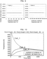
- Fig. 9 is a set of graphs illustrating the evolution of thermal resistance per unit area of the partition members in Comparative example 1.
- the vertical axis represents thermal resistance per unit area (m 2 ⁇ K/W)and the horizontal axis represents the surface average temperature (°C) of the respective partition members 1.
- the value of thermal resistance per unit area ( ⁇ 1 ) at a surface average temperature of 190°C of the partition member 11 (Spacer 1) and of the partition member 12 (Spacer 2) was 4.2 ⁇ 10 -3 m 2 ⁇ K/W
- the value of thermal resistance per unit area ( ⁇ 2 ) at an average temperature of 70°C was 4.2 ⁇ 10 -3 m 2 ⁇ K/W. That is, the partition members 1 in Comparative example 1 fail to satisfy the conditions of (Expression 1) and (Expression 2) described above pertaining to thermal resistance per unit area.
- Example 1 the partition members 1 were assumed to be high-performance partition members having a switching function whereby thermal conductivity changes at the point in time where the surface temperature of the partition members 1, on the side of abnormally heated cell, reaches a predetermined temperature.
- the thickness of the partition members 1 was set to 1.0 mm.
- Various conditions pertaining to the bus bars 3 and the case 4 were set to be identical to those in Comparative example 1.
- each partition member 1 in such a structure was set to 150°C, the initial thermal conductivity to 1.0 W/m ⁇ K and the thermal conductivity after switching to 0.10 W/m ⁇ K, and there were estimated the temperature inside each cell 2, as well as the surface average temperature and thermal resistance per unit area of each partition member 1.
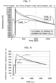
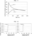
- Fig. 11 is a graph illustrating the evolution of surface average temperature of partition members in Example 1.
- the vertical axis represents the surface average temperature (°C) of the partition members 1 and the horizontal axis represents the time (seconds) after the cell 21 has reached an abnormal heating state. It was estimated that immediately after the cell 21 reaches an abnormal heating state the surface average temperature of the partition member 11 (Spacer 1) rises rapidly and exceeds 400°C, but the surface average temperature of the partition member 12 (Spacer 2) converges at about 160°C, without rising rapidly.
- Comparative example 2 and Comparative example 3 illustrate examples envisaging partition members 1 not having a switching function.
- the partition members 1 are assumed to be partition members 1 of lower thermal conductivity than that in Comparative example 1, with thickness set to 1.0 mm and thermal conductivity set to 0.10 W/m ⁇ K.
- Various conditions pertaining to the bus bars 3 and the case 4 were set to be identical to those in Comparative example 1.
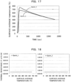
- Fig. 14 is a graph illustrating the evolution of the surface average temperature of partition members in Comparative example 2.
- the vertical axis represents the surface average temperature (°C) of partition members 1 and the horizontal axis represents the time (seconds) after the cell 21 has reached an abnormal heating state.
- the surface average temperature of the partition member 11 (Spacer 1) began rising about 250 seconds after the cell 21 reached an abnormal heating state. From these results it was estimated that in a case where the thermal insulation properties of the members 1 is enhanced, the heat generated by the cell 21 is not eliminated efficiently, at an initial stage where the cell 21 has reached the abnormal heating state and as a result spread of burning is not suppressed.
- Fig. 15 is a set of graphs illustrating the evolution of thermal resistance per unit area of the partition members in Comparative example 2.
- the vertical axis represents thermal resistance per unit area (m 2 ⁇ K/W)and the horizontal axis represents the surface average temperature (°C) of the respective partition members 1.
- the value of thermal resistance per unit area ( ⁇ 1 ) at a surface average temperature of 190°C of the partition member 11 (Spacer 1) and of the partition member 12 (Spacer 2) was 1.0 ⁇ 10 -2 m 2 ⁇ K/W
- the value of thermal resistance per unit area ( ⁇ 2 ) at an average temperature of 70°C was 1.0 ⁇ 10 -2 m 2 ⁇ K/W. That is, the partition members 1 in Comparative example 2 satisfy the condition of (Expression 1) described above pertaining to thermal resistance per unit area, but not the condition of (Expression 2) .
- Fig. 16 is a graph illustrating changes in temperature in the interior of the cells in Comparative example 3.
- the vertical axis represents absolute temperature (K) in the interior of the cells 2, and the horizontal axis represents the time (seconds) elapsed since the cell 21 has reached an abnormal heating state.
- the graph indicated that the time required for the occurrence of spread of burning from the abnormally heated cell 21 to the cell 22 and cell 23 was shorter than that in Comparative example 1, in which partition members 1 made of a general resin were used, and that the cell 22 and cell 23 underwent abnormal heating substantially simultaneously with cell 21.
- Comparative example 4 the partition members 1 were set to have a thickness of 1.0 mm, a switching temperature of 150°C, an initial thermal conductivity of 0.24 W/m ⁇ K, and a thermal conductivity after switching of 0.10 W/m ⁇ K.
- Various conditions pertaining to the bus bars 3 and the case 4 were set to be identical to those in Comparative example 1.
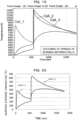
- Fig. 20 is a graph illustrating the evolution of surface average temperature of partition members in Comparative example 4.
- the vertical axis represents the surface average temperature (°C) of the partition members 1 and the horizontal axis represents the time (seconds) after the cell 21 has reached an abnormal heating state. It was estimated that immediately after the cell 21 reaches an abnormal heating state, the surface average temperature of the partition member 11 (Spacer 1) rises rapidly beyond 400°C, and after about 600 seconds have elapsed, also the surface average temperature of the partition member 12 (Spacer 2) rises rapidly beyond 800°C. From the above results it was estimated that even when the partition members 1 have a switching function, spread of burning cannot be reduced unless the thermal conductivity of the partition members 1 is properly controlled.
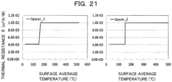
- Fig. 21 is a set of graphs illustrating the evolution of thermal resistance per unit area of the partition members in Comparative example 4.
- the vertical axis represents thermal resistance per unit area (m 2 ⁇ K/W) and the horizontal axis represents the surface average temperature (°C) of the respective partition members 1.
- the value of thermal resistance per unit area ( ⁇ 1 ) at a surface average temperature of 190°C of the partition member 11 (Spacer 1) and of the partition member 12 (Spacer 2) was 1.0 ⁇ 10 -2 m 2 ⁇ K/W
- the value of thermal resistance per unit area ( ⁇ 2 ) at an average temperature of 70°C was 4.2 ⁇ 10 -3 m 2 ⁇ K/W. That is, the partition members 1 in Comparative example 4 satisfy the condition of (Expression 1) described above pertaining to thermal resistance per unit area, but not the condition of (Expression 2) .
Landscapes
- Chemical & Material Sciences (AREA)
- Chemical Kinetics & Catalysis (AREA)
- Electrochemistry (AREA)
- General Chemical & Material Sciences (AREA)
- Engineering & Computer Science (AREA)
- Manufacturing & Machinery (AREA)
- Physics & Mathematics (AREA)
- Algebra (AREA)
- General Physics & Mathematics (AREA)
- Mathematical Analysis (AREA)
- Mathematical Optimization (AREA)
- Pure & Applied Mathematics (AREA)
- Aviation & Aerospace Engineering (AREA)
- Secondary Cells (AREA)
- Battery Mounting, Suspending (AREA)
Claims (9)
- Trennelement (1A, 1B, 11, 12), das zwei Oberflächen (1a, 1b, 1c, 1d) in einer Dickenrichtung aufweist und das einzelne Zellen (21, 22, 23) trennt, die eine zusammengesetzte Batterie (10) bilden, wobei, wenn die Durchschnittstemperatur einer der beiden Oberflächen 180 °C übersteigt, ein Wärmewiderstand pro Flächeneinheit (θ1) in der Dickenrichtung den nachstehenden Ausdruck 1 erfüllt; und
wenn die Durchschnittstemperaturen der beiden Oberflächen 80 °C nicht überschreiten, ein Wärmewiderstand pro Flächeneinheit (θ2) in der Dickenrichtung den nachstehenden Ausdruck 2 erfüllt:

- Trennelement nach Anspruch 1, wobei, wenn die Durchschnittstemperatur einer der beiden Oberflächen 180 °C oder höher ist, die Wärmeleitfähigkeit in der Dickenrichtung 2,0×10⁻² W/m-K oder mehr und 2,0 W/m-K oder weniger beträgt; und
wenn die Durchschnittstemperaturen der beiden Oberflächen 80 °C oder weniger betragen, die Wärmeleitfähigkeit in der Dickenrichtung 5,0×10⁻² W/m-K oder mehr und 50 W/m·K oder weniger beträgt. - Trennelement nach Anspruch 1 oder 2, wobei, wenn die Dicke der einzelnen Zellen mit L (mm) bezeichnet wird, die Dicke in der Dickenrichtung L/50 mm oder mehr und L/10 mm oder weniger beträgt.
- Trennelement nach einem der Ansprüche 1 bis 3, wobei, wenn die Durchschnittstemperatur einer der beiden Oberflächen 180 °C übersteigt und 300 °C oder weniger beträgt, der Wärmewiderstand pro Flächeneinheit (θ1) in der Dickenrichtung den Ausdruck 1 erfüllt; und
wenn die Durchschnittstemperaturen der beiden Oberflächen 80 °C nicht überschreiten, der Wärmewiderstand pro Flächeneinheit (θ2) in der Dickenrichtung den Ausdruck 2 erfüllt. - Zusammengesetzte Batterie, die das Trennelement nach einem der Ansprüche 1 bis 4 aufweist.
- Zusammengesetzte Batterie (10), die aufweist:mehrere einzelne Zellen, die eine erste einzelne Zelle (21), eine zweite einzelne Zelle (22) und eine dritte einzelne Zelle (23) aufweisen; undein erstes Trennelement (11), das die erste einzelne Zelle von der zweiten einzelnen Zelle trennt, und ein zweites Trennelement (12), das die zweite einzelne Zelle von der dritten einzelnen Zellen trennt,wobei jeweils das erste Trennelement und das zweite Trennelement eine Flüssigkeit enthalten, undwobei, wenn die zweite einzelne Zelle von einem Normalzustand abweicht, weil Wärme von der ersten einzelnen Zelle einen anormalen Erwärmungszustand erreicht hat, die Wärmemenge, die von der ersten einzelnen Zelle über das erste Trennelement zur zweiten einzelnen Zelle übertragen wird, durch das erste Trennelement reduziert wird und die Wärmemenge, die von der ersten einzelnen Zelle zur dritten einzelnen Zelle übertragen wird, die den Normalzustand beibehält, durch das zweite Trennelement nicht reduziert wird.
- Zusammengesetzte Batterie nach Anspruch 6, wobei die von der ersten einzelnen Zelle auf die zweite einzelne Zelle übertragene Wärmemenge durch eine Erhöhung des Wärmewiderstands pro Flächeneinheit des ersten Trennelements verringert wird.
- Zusammengesetzte Batterie nach Anspruch 6 oder 7, wobei selbst dann, wenn die zweite einzelne Zelle von einem Normalzustand abweicht, der Wärmewiderstand pro Flächeneinheit des zweiten Trennelements nicht zunimmt und die von der ersten einzelnen Zelle auf die dritte einzelne Zelle übertragene Wärmemenge nicht verringert wird.
- Verfahren zur Steuerung der Wärmeübertragung in einer zusammengesetzten Batterie (10), in der einzelne Zellen (21, 22, 23) durch ein Trennelement (1A, 1B, 11, 12) getrennt sind,wobei das Trennelement zwei Oberflächen (1a, 1b, 1c, 1d) in einer Dickenrichtung aufweist, wobei eine der Oberflächen eine erste Oberfläche ist, die einer ersten einzelnen Zelle gegenüberliegt, und die andere Oberfläche eine zweite Oberfläche ist, die einer zweiten einzelnen Zelle gegenüberliegt;wenn eine Durchschnittstemperatur der ersten Oberfläche 80 °C nicht übersteigt, ein Wärmewiderstand pro Flächeneinheit (θ2) in der Dickenrichtung den nachstehenden Ausdruck 2 erfüllt, wodurch Wärme von der ersten einzelnen Zelle über das Trennelement auf die zweite einzelne Zelle übertragen wird; undwenn die erste einzelne Zelle einen anormalen Erwärmungszustand erreicht, die zweite einzelne Zelle von einem normalen Zustand aufgrund von Wärme abweicht, die von der ersten einzelnen Zelle über das Trennelement übertragen wird, und die Durchschnittstemperatur der ersten Oberfläche 180 °C aufgrund von Wärme von der ersten einzelnen Zelle übersteigt, dann ein Wärmewiderstand pro Flächeneinheit (θ1) in der Dickenrichtung den folgenden Ausdruck 1 erfüllt, wodurch eine Wärmemenge, die von der ersten einzelnen Zelle über das Trennelement übertragen wird, reduziert wird:


Priority Applications (1)
| Application Number | Priority Date | Filing Date | Title |
|---|---|---|---|
| EP25166960.2A EP4567970A3 (de) | 2016-12-27 | 2017-12-27 | Trennelement, zusammengesetzte batterie und wärmeübertragungssteuerungsverfahren für eine zusammengesetzte batterie |
Applications Claiming Priority (2)
| Application Number | Priority Date | Filing Date | Title |
|---|---|---|---|
| JP2016254342 | 2016-12-27 | ||
| PCT/JP2017/047090 WO2018124231A1 (ja) | 2016-12-27 | 2017-12-27 | 仕切り部材、組電池及び組電池の熱伝達制御方法 |
Related Child Applications (1)
| Application Number | Title | Priority Date | Filing Date |
|---|---|---|---|
| EP25166960.2A Division EP4567970A3 (de) | 2016-12-27 | 2017-12-27 | Trennelement, zusammengesetzte batterie und wärmeübertragungssteuerungsverfahren für eine zusammengesetzte batterie |
Publications (4)
| Publication Number | Publication Date |
|---|---|
| EP3565020A1 EP3565020A1 (de) | 2019-11-06 |
| EP3565020A4 EP3565020A4 (de) | 2020-01-08 |
| EP3565020B1 true EP3565020B1 (de) | 2025-04-16 |
| EP3565020C0 EP3565020C0 (de) | 2025-04-16 |
Family
ID=62709555
Family Applications (2)
| Application Number | Title | Priority Date | Filing Date |
|---|---|---|---|
| EP25166960.2A Pending EP4567970A3 (de) | 2016-12-27 | 2017-12-27 | Trennelement, zusammengesetzte batterie und wärmeübertragungssteuerungsverfahren für eine zusammengesetzte batterie |
| EP17886854.3A Active EP3565020B1 (de) | 2016-12-27 | 2017-12-27 | Trennwand, zusammengesetzte batterie und wärmeübertragungsteuerungsverfahren für eine zusammengesetzte batterie |
Family Applications Before (1)
| Application Number | Title | Priority Date | Filing Date |
|---|---|---|---|
| EP25166960.2A Pending EP4567970A3 (de) | 2016-12-27 | 2017-12-27 | Trennelement, zusammengesetzte batterie und wärmeübertragungssteuerungsverfahren für eine zusammengesetzte batterie |
Country Status (7)
| Country | Link |
|---|---|
| US (4) | US20190319223A1 (de) |
| EP (2) | EP4567970A3 (de) |
| JP (1) | JP6835101B2 (de) |
| KR (3) | KR102650754B1 (de) |
| CN (2) | CN110114903B (de) |
| CA (1) | CA3048603A1 (de) |
| WO (1) | WO2018124231A1 (de) |
Families Citing this family (10)
| Publication number | Priority date | Publication date | Assignee | Title |
|---|---|---|---|---|
| JP7306401B2 (ja) * | 2018-09-14 | 2023-07-11 | 三菱ケミカル株式会社 | 充填部材及び組電池 |
| JP7167802B2 (ja) * | 2019-03-26 | 2022-11-09 | 三菱ケミカル株式会社 | 仕切り部材及び組電池 |
| EP3952010A4 (de) * | 2019-03-28 | 2023-05-24 | Mitsubishi Chemical Corporation | Trennelement und batterieanordnung |
| US11515587B2 (en) * | 2019-10-10 | 2022-11-29 | Robert Bosch Gmbh | Physics-based control of battery temperature |
| CN115009524B (zh) * | 2022-07-17 | 2023-11-17 | 西北工业大学 | 一种基于正常运行状态下的太阳能飞机热控系统及方法 |
| JPWO2024143441A1 (de) | 2022-12-28 | 2024-07-04 | ||
| CN120453552A (zh) * | 2024-02-06 | 2025-08-08 | 比亚迪股份有限公司 | 电池组件和装置 |
| CN222867787U (zh) * | 2024-06-28 | 2025-05-13 | 比亚迪股份有限公司 | 电池组件、电池包和用电设备 |
| WO2026029616A1 (ko) * | 2024-08-02 | 2026-02-05 | 주식회사 엘지화학 | 흡열 장치 |
| KR20260020060A (ko) * | 2024-08-02 | 2026-02-10 | 주식회사 엘지화학 | 흡열 장치 |
Family Cites Families (30)
| Publication number | Priority date | Publication date | Assignee | Title |
|---|---|---|---|---|
| JPS49534B1 (de) | 1969-05-16 | 1974-01-08 | ||
| JPS5651210Y2 (de) | 1976-10-07 | 1981-11-30 | ||
| JP4576903B2 (ja) | 2004-06-29 | 2010-11-10 | 三菱化学株式会社 | 温度分布評価方法並びにシミュレーション装置及びシミュレーションプログラム |
| US7981536B2 (en) | 2006-08-31 | 2011-07-19 | Toray Tonen Specialty Separator Godo Kaisha | Microporous membrane, battery separator and battery |
| JP2009135088A (ja) | 2007-10-29 | 2009-06-18 | Panasonic Corp | 電池パックおよび電池搭載機器 |
| JP2010061982A (ja) * | 2008-09-03 | 2010-03-18 | Toyota Motor Corp | 蓄電装置 |
| JP5326480B2 (ja) | 2008-10-14 | 2013-10-30 | トヨタ自動車株式会社 | 蓄電装置 |
| JP2010165597A (ja) * | 2009-01-16 | 2010-07-29 | Toyota Motor Corp | 蓄電装置 |
| JP4900534B2 (ja) | 2009-02-24 | 2012-03-21 | パナソニック株式会社 | 電池モジュールとそれを用いた電池モジュール集合体 |
| US8372269B2 (en) | 2009-10-02 | 2013-02-12 | Basf Corporation | Heavy metals trapping co-catalyst for FCC processes |
| JP5740103B2 (ja) * | 2009-10-19 | 2015-06-24 | 日東電工株式会社 | 熱伝導部材、及びそれを用いた組電池装置 |
| US20110293986A1 (en) * | 2009-11-25 | 2011-12-01 | Katsumi Kozu | Battery module |
| DE112010004856A5 (de) * | 2009-12-18 | 2012-12-13 | Magna E-Car Systems Gmbh & Co Og | Kühl-/Heizelement für einen Akkumulator |
| TWI419391B (zh) * | 2009-12-25 | 2013-12-11 | Ind Tech Res Inst | 電池系統中的散熱與熱失控擴散防護結構 |
| CN102117945A (zh) * | 2009-12-31 | 2011-07-06 | 财团法人工业技术研究院 | 电池系统中的散热与热失控扩散防护结构 |
| EP2555276A1 (de) * | 2010-03-30 | 2013-02-06 | Panasonic Corporation | Batteriepack |
| JP5572442B2 (ja) * | 2010-04-27 | 2014-08-13 | 日立ビークルエナジー株式会社 | 液冷式蓄電システム |
| DE102010030881A1 (de) * | 2010-07-02 | 2012-01-05 | Robert Bosch Gmbh | Thermische Entkopplung von Batteriezellen im Störfall |
| US9293794B2 (en) * | 2010-09-09 | 2016-03-22 | Panasonic intellectual property Management co., Ltd | Battery module |
| WO2012060031A1 (ja) * | 2010-11-05 | 2012-05-10 | パナソニック株式会社 | 電池モジュール |
| JP2013033723A (ja) * | 2011-07-04 | 2013-02-14 | Nissan Motor Co Ltd | 組電池 |
| US8993145B2 (en) * | 2011-09-19 | 2015-03-31 | Zee.Aero Inc. | Preventing cell thermal runaway propagation within a battery |
| KR101272524B1 (ko) * | 2011-09-20 | 2013-06-11 | 현대자동차주식회사 | 배터리 셀용 방열판 및 이를 갖는 배터리 모듈 |
| KR101417248B1 (ko) * | 2012-02-08 | 2014-07-09 | 현대자동차주식회사 | 배터리 셀 모듈용 방열 플레이트 및 이를 갖는 배터리 셀 모듈 |
| JP6153702B2 (ja) * | 2012-05-08 | 2017-06-28 | 東洋ゴム工業株式会社 | 熱伝導率可変材料 |
| JP2014127403A (ja) * | 2012-12-27 | 2014-07-07 | Mitsubishi Heavy Ind Ltd | 電池モジュール |
| JP2015208894A (ja) | 2014-04-24 | 2015-11-24 | 東レバッテリーセパレータフィルム株式会社 | ポリオレフィン製積層微多孔膜 |
| JP6135660B2 (ja) * | 2014-12-25 | 2017-05-31 | トヨタ自動車株式会社 | 組電池 |
| EP3062381B1 (de) * | 2015-02-26 | 2018-04-11 | Magneti Marelli S.p.A. | Kühlkreislauf mit kühlflüssigkeit für lithiumbatterien und fahrzeug mit dem kühlkreislauf |
| CN105720225B (zh) * | 2016-03-31 | 2018-05-04 | 苏州工业园区职业技术学院 | 一种动力电池组快捷连接件 |
-
2017
- 2017-12-27 EP EP25166960.2A patent/EP4567970A3/de active Pending
- 2017-12-27 KR KR1020197019964A patent/KR102650754B1/ko active Active
- 2017-12-27 EP EP17886854.3A patent/EP3565020B1/de active Active
- 2017-12-27 KR KR1020267004855A patent/KR20260036375A/ko active Pending
- 2017-12-27 KR KR1020247009201A patent/KR102934157B1/ko active Active
- 2017-12-27 CN CN201780080853.2A patent/CN110114903B/zh active Active
- 2017-12-27 WO PCT/JP2017/047090 patent/WO2018124231A1/ja not_active Ceased
- 2017-12-27 JP JP2018559611A patent/JP6835101B2/ja active Active
- 2017-12-27 CA CA3048603A patent/CA3048603A1/en active Pending
- 2017-12-27 CN CN202211104938.9A patent/CN115472995B/zh active Active
-
2019
- 2019-06-26 US US16/452,587 patent/US20190319223A1/en not_active Abandoned
-
2022
- 2022-03-25 US US17/656,632 patent/US11837705B2/en active Active
-
2023
- 2023-11-02 US US18/500,945 patent/US12412943B2/en active Active
-
2025
- 2025-08-13 US US19/299,237 patent/US20250372753A1/en active Pending
Non-Patent Citations (1)
| Title |
|---|
| LIN YING ET AL: "Epoxy thermoset resins with high pristine thermal conductivity", HIGH VOLTAGE, THE INSTITUTION OF ENGINEERING AND TECHNOLOGY, MICHAEL FARADAY HOUSE, SIX HILLS WAY, STEVENAGE, HERTS. SG1 2AY, UK, vol. 2, no. 3, 1 September 2017 (2017-09-01), pages 139 - 146, XP006076284, ISSN: 2397-7264, DOI: 10.1049/HVE.2017.0120 * |
Also Published As
| Publication number | Publication date |
|---|---|
| KR102650754B1 (ko) | 2024-03-22 |
| EP3565020A1 (de) | 2019-11-06 |
| US20220223946A1 (en) | 2022-07-14 |
| US11837705B2 (en) | 2023-12-05 |
| CN110114903B (zh) | 2022-09-27 |
| US12412943B2 (en) | 2025-09-09 |
| EP3565020C0 (de) | 2025-04-16 |
| EP4567970A3 (de) | 2026-01-21 |
| CN110114903A (zh) | 2019-08-09 |
| US20190319223A1 (en) | 2019-10-17 |
| KR20240042179A (ko) | 2024-04-01 |
| US20240072325A1 (en) | 2024-02-29 |
| CN115472995A (zh) | 2022-12-13 |
| KR20260036375A (ko) | 2026-03-16 |
| EP4567970A2 (de) | 2025-06-11 |
| JPWO2018124231A1 (ja) | 2019-11-14 |
| KR102934157B1 (ko) | 2026-03-05 |
| CN115472995B (zh) | 2025-05-30 |
| KR20190097112A (ko) | 2019-08-20 |
| JP6835101B2 (ja) | 2021-02-24 |
| EP3565020A4 (de) | 2020-01-08 |
| US20250372753A1 (en) | 2025-12-04 |
| CA3048603A1 (en) | 2018-07-05 |
| WO2018124231A1 (ja) | 2018-07-05 |
Similar Documents
| Publication | Publication Date | Title |
|---|---|---|
| US12412943B2 (en) | Partition member, assembled battery and method for controlling heat transfer in an assembled battery | |
| JP7354842B2 (ja) | 仕切り部材及び組電池 | |
| EP2210311B1 (de) | Fahrzeug mit batteriesystem | |
| US12469903B2 (en) | Battery cell pack for electric vehicle | |
| Chen et al. | Thermal analysis of lithium polymer electrolyte batteries by a two dimensional model—thermal behaviour and design optimization | |
| EP3142173B1 (de) | Positivelektrode für eine sekundärbatterie mit wasserfreiem elektrolyt und sekundärbatterien mit wasserfreiem elektrolyt | |
| CN112106228A (zh) | 具有提高的安全性的电池模块、包括电池模块的电池组和包括电池组的车辆 | |
| JP2011090830A (ja) | 2次電池 | |
| JP6954213B2 (ja) | 充填部材、組電池及び熱伝達の制御方法 | |
| US11929478B2 (en) | Filling member and battery pack | |
| JP2019102244A (ja) | 仕切り部材及び組電池 | |
| JP2019185846A (ja) | 充填部材、組電池、及び熱伝達の制御方法 |
Legal Events
| Date | Code | Title | Description |
|---|---|---|---|
| STAA | Information on the status of an ep patent application or granted ep patent |
Free format text: STATUS: THE INTERNATIONAL PUBLICATION HAS BEEN MADE |
|
| PUAI | Public reference made under article 153(3) epc to a published international application that has entered the european phase |
Free format text: ORIGINAL CODE: 0009012 |
|
| STAA | Information on the status of an ep patent application or granted ep patent |
Free format text: STATUS: REQUEST FOR EXAMINATION WAS MADE |
|
| 17P | Request for examination filed |
Effective date: 20190727 |
|
| AK | Designated contracting states |
Kind code of ref document: A1 Designated state(s): AL AT BE BG CH CY CZ DE DK EE ES FI FR GB GR HR HU IE IS IT LI LT LU LV MC MK MT NL NO PL PT RO RS SE SI SK SM TR |
|
| AX | Request for extension of the european patent |
Extension state: BA ME |
|
| A4 | Supplementary search report drawn up and despatched |
Effective date: 20191206 |
|
| RIC1 | Information provided on ipc code assigned before grant |
Ipc: H01M 10/625 20140101ALI20191202BHEP Ipc: H01M 10/617 20140101ALI20191202BHEP Ipc: H01M 10/658 20140101ALI20191202BHEP Ipc: H01M 2/10 20060101AFI20191202BHEP Ipc: H01M 10/627 20140101ALI20191202BHEP Ipc: H01M 2/02 20060101ALI20191202BHEP Ipc: H01M 10/651 20140101ALI20191202BHEP Ipc: H01M 10/647 20140101ALI20191202BHEP |
|
| DAV | Request for validation of the european patent (deleted) | ||
| DAX | Request for extension of the european patent (deleted) | ||
| STAA | Information on the status of an ep patent application or granted ep patent |
Free format text: STATUS: EXAMINATION IS IN PROGRESS |
|
| 17Q | First examination report despatched |
Effective date: 20220811 |
|
| REG | Reference to a national code |
Ref country code: DE Ref legal event code: R079 Free format text: PREVIOUS MAIN CLASS: H01M0002100000 Ipc: H01M0010655500 Ref document number: 602017088998 Country of ref document: DE |
|
| GRAP | Despatch of communication of intention to grant a patent |
Free format text: ORIGINAL CODE: EPIDOSNIGR1 |
|
| STAA | Information on the status of an ep patent application or granted ep patent |
Free format text: STATUS: GRANT OF PATENT IS INTENDED |
|
| RIC1 | Information provided on ipc code assigned before grant |
Ipc: H01M 10/6555 20140101AFI20240322BHEP |
|
| INTG | Intention to grant announced |
Effective date: 20240429 |
|
| GRAJ | Information related to disapproval of communication of intention to grant by the applicant or resumption of examination proceedings by the epo deleted |
Free format text: ORIGINAL CODE: EPIDOSDIGR1 |
|
| STAA | Information on the status of an ep patent application or granted ep patent |
Free format text: STATUS: EXAMINATION IS IN PROGRESS |
|
| INTC | Intention to grant announced (deleted) | ||
| GRAS | Grant fee paid |
Free format text: ORIGINAL CODE: EPIDOSNIGR3 |
|
| STAA | Information on the status of an ep patent application or granted ep patent |
Free format text: STATUS: GRANT OF PATENT IS INTENDED |
|
| GRAP | Despatch of communication of intention to grant a patent |
Free format text: ORIGINAL CODE: EPIDOSNIGR1 |
|
| GRAJ | Information related to disapproval of communication of intention to grant by the applicant or resumption of examination proceedings by the epo deleted |
Free format text: ORIGINAL CODE: EPIDOSDIGR1 |
|
| GRAS | Grant fee paid |
Free format text: ORIGINAL CODE: EPIDOSNIGR3 |
|
| GRAP | Despatch of communication of intention to grant a patent |
Free format text: ORIGINAL CODE: EPIDOSNIGR1 |
|
| GRAJ | Information related to disapproval of communication of intention to grant by the applicant or resumption of examination proceedings by the epo deleted |
Free format text: ORIGINAL CODE: EPIDOSDIGR1 |
|
| STAA | Information on the status of an ep patent application or granted ep patent |
Free format text: STATUS: EXAMINATION IS IN PROGRESS |
|
| GRAS | Grant fee paid |
Free format text: ORIGINAL CODE: EPIDOSNIGR3 |
|
| STAA | Information on the status of an ep patent application or granted ep patent |
Free format text: STATUS: GRANT OF PATENT IS INTENDED |
|
| GRAJ | Information related to disapproval of communication of intention to grant by the applicant or resumption of examination proceedings by the epo deleted |
Free format text: ORIGINAL CODE: EPIDOSDIGR1 |
|
| GRAP | Despatch of communication of intention to grant a patent |
Free format text: ORIGINAL CODE: EPIDOSNIGR1 |
|
| STAA | Information on the status of an ep patent application or granted ep patent |
Free format text: STATUS: EXAMINATION IS IN PROGRESS |
|
| GRAS | Grant fee paid |
Free format text: ORIGINAL CODE: EPIDOSNIGR3 |
|
| STAA | Information on the status of an ep patent application or granted ep patent |
Free format text: STATUS: GRANT OF PATENT IS INTENDED |
|
| GRAP | Despatch of communication of intention to grant a patent |
Free format text: ORIGINAL CODE: EPIDOSNIGR1 |
|
| GRAJ | Information related to disapproval of communication of intention to grant by the applicant or resumption of examination proceedings by the epo deleted |
Free format text: ORIGINAL CODE: EPIDOSDIGR1 |
|
| STAA | Information on the status of an ep patent application or granted ep patent |
Free format text: STATUS: EXAMINATION IS IN PROGRESS |
|
| GRAS | Grant fee paid |
Free format text: ORIGINAL CODE: EPIDOSNIGR3 |
|
| STAA | Information on the status of an ep patent application or granted ep patent |
Free format text: STATUS: GRANT OF PATENT IS INTENDED |
|
| GRAP | Despatch of communication of intention to grant a patent |
Free format text: ORIGINAL CODE: EPIDOSNIGR1 |
|
| INTG | Intention to grant announced |
Effective date: 20241106 |
|
| INTG | Intention to grant announced |
Effective date: 20241118 |
|
| GRAA | (expected) grant |
Free format text: ORIGINAL CODE: 0009210 |
|
| STAA | Information on the status of an ep patent application or granted ep patent |
Free format text: STATUS: THE PATENT HAS BEEN GRANTED |
|
| AK | Designated contracting states |
Kind code of ref document: B1 Designated state(s): AL AT BE BG CH CY CZ DE DK EE ES FI FR GB GR HR HU IE IS IT LI LT LU LV MC MK MT NL NO PL PT RO RS SE SI SK SM TR |
|
| REG | Reference to a national code |
Ref country code: GB Ref legal event code: FG4D |
|
| REG | Reference to a national code |
Ref country code: CH Ref legal event code: EP Ref country code: DE Ref legal event code: R096 Ref document number: 602017088998 Country of ref document: DE |
|
| REG | Reference to a national code |
Ref country code: IE Ref legal event code: FG4D |
|
| U01 | Request for unitary effect filed |
Effective date: 20250424 |
|
| U07 | Unitary effect registered |
Designated state(s): AT BE BG DE DK EE FI FR IT LT LU LV MT NL PT RO SE SI Effective date: 20250430 |
|
| PG25 | Lapsed in a contracting state [announced via postgrant information from national office to epo] |
Ref country code: ES Free format text: LAPSE BECAUSE OF FAILURE TO SUBMIT A TRANSLATION OF THE DESCRIPTION OR TO PAY THE FEE WITHIN THE PRESCRIBED TIME-LIMIT Effective date: 20250416 |
|
| PG25 | Lapsed in a contracting state [announced via postgrant information from national office to epo] |
Ref country code: NO Free format text: LAPSE BECAUSE OF FAILURE TO SUBMIT A TRANSLATION OF THE DESCRIPTION OR TO PAY THE FEE WITHIN THE PRESCRIBED TIME-LIMIT Effective date: 20250716 Ref country code: GR Free format text: LAPSE BECAUSE OF FAILURE TO SUBMIT A TRANSLATION OF THE DESCRIPTION OR TO PAY THE FEE WITHIN THE PRESCRIBED TIME-LIMIT Effective date: 20250717 |
|
| PG25 | Lapsed in a contracting state [announced via postgrant information from national office to epo] |
Ref country code: PL Free format text: LAPSE BECAUSE OF FAILURE TO SUBMIT A TRANSLATION OF THE DESCRIPTION OR TO PAY THE FEE WITHIN THE PRESCRIBED TIME-LIMIT Effective date: 20250416 |
|
| PG25 | Lapsed in a contracting state [announced via postgrant information from national office to epo] |
Ref country code: HR Free format text: LAPSE BECAUSE OF FAILURE TO SUBMIT A TRANSLATION OF THE DESCRIPTION OR TO PAY THE FEE WITHIN THE PRESCRIBED TIME-LIMIT Effective date: 20250416 |
|
| PG25 | Lapsed in a contracting state [announced via postgrant information from national office to epo] |
Ref country code: RS Free format text: LAPSE BECAUSE OF FAILURE TO SUBMIT A TRANSLATION OF THE DESCRIPTION OR TO PAY THE FEE WITHIN THE PRESCRIBED TIME-LIMIT Effective date: 20250716 |
|
| PG25 | Lapsed in a contracting state [announced via postgrant information from national office to epo] |
Ref country code: IS Free format text: LAPSE BECAUSE OF FAILURE TO SUBMIT A TRANSLATION OF THE DESCRIPTION OR TO PAY THE FEE WITHIN THE PRESCRIBED TIME-LIMIT Effective date: 20250816 |
|
| PG25 | Lapsed in a contracting state [announced via postgrant information from national office to epo] |
Ref country code: SM Free format text: LAPSE BECAUSE OF FAILURE TO SUBMIT A TRANSLATION OF THE DESCRIPTION OR TO PAY THE FEE WITHIN THE PRESCRIBED TIME-LIMIT Effective date: 20250416 |
|
| PG25 | Lapsed in a contracting state [announced via postgrant information from national office to epo] |
Ref country code: CZ Free format text: LAPSE BECAUSE OF FAILURE TO SUBMIT A TRANSLATION OF THE DESCRIPTION OR TO PAY THE FEE WITHIN THE PRESCRIBED TIME-LIMIT Effective date: 20250416 |
|
| PG25 | Lapsed in a contracting state [announced via postgrant information from national office to epo] |
Ref country code: SK Free format text: LAPSE BECAUSE OF FAILURE TO SUBMIT A TRANSLATION OF THE DESCRIPTION OR TO PAY THE FEE WITHIN THE PRESCRIBED TIME-LIMIT Effective date: 20250416 |
|
| U20 | Renewal fee for the european patent with unitary effect paid |
Year of fee payment: 9 Effective date: 20251229 |
|
| PLBE | No opposition filed within time limit |
Free format text: ORIGINAL CODE: 0009261 |
|
| STAA | Information on the status of an ep patent application or granted ep patent |
Free format text: STATUS: NO OPPOSITION FILED WITHIN TIME LIMIT |
|
| REG | Reference to a national code |
Ref country code: CH Ref legal event code: L10 Free format text: ST27 STATUS EVENT CODE: U-0-0-L10-L00 (AS PROVIDED BY THE NATIONAL OFFICE) Effective date: 20260225 |
|
| 26N | No opposition filed |
Effective date: 20260119 |