EP3565102A1 - Wechselrichterantriebsvorrichtung und elektrisches fahrzeugsystem damit - Google Patents
Wechselrichterantriebsvorrichtung und elektrisches fahrzeugsystem damit Download PDFInfo
- Publication number
- EP3565102A1 EP3565102A1 EP17886063.1A EP17886063A EP3565102A1 EP 3565102 A1 EP3565102 A1 EP 3565102A1 EP 17886063 A EP17886063 A EP 17886063A EP 3565102 A1 EP3565102 A1 EP 3565102A1
- Authority
- EP
- European Patent Office
- Prior art keywords
- voltage
- motor
- frequency
- ridge
- trough
- Prior art date
- Legal status (The legal status is an assumption and is not a legal conclusion. Google has not performed a legal analysis and makes no representation as to the accuracy of the status listed.)
- Granted
Links
Images







Classifications
-
- H—ELECTRICITY
- H02—GENERATION; CONVERSION OR DISTRIBUTION OF ELECTRIC POWER
- H02P—CONTROL OR REGULATION OF ELECTRIC MOTORS, ELECTRIC GENERATORS OR DYNAMO-ELECTRIC CONVERTERS; CONTROLLING TRANSFORMERS, REACTORS OR CHOKE COILS
- H02P27/00—Arrangements or methods for the control of AC motors characterised by the kind of supply voltage
- H02P27/04—Arrangements or methods for the control of AC motors characterised by the kind of supply voltage using variable-frequency supply voltage, e.g. inverter or converter supply voltage
- H02P27/06—Arrangements or methods for the control of AC motors characterised by the kind of supply voltage using variable-frequency supply voltage, e.g. inverter or converter supply voltage using DC to AC converters or inverters
- H02P27/08—Arrangements or methods for the control of AC motors characterised by the kind of supply voltage using variable-frequency supply voltage, e.g. inverter or converter supply voltage using DC to AC converters or inverters with pulse width modulation
-
- H—ELECTRICITY
- H02—GENERATION; CONVERSION OR DISTRIBUTION OF ELECTRIC POWER
- H02M—APPARATUS FOR CONVERSION BETWEEN AC AND AC, BETWEEN AC AND DC, OR BETWEEN DC AND DC, AND FOR USE WITH MAINS OR SIMILAR POWER SUPPLY SYSTEMS; CONVERSION OF DC OR AC INPUT POWER INTO SURGE OUTPUT POWER; CONTROL OR REGULATION THEREOF
- H02M7/00—Conversion of AC power input into DC power output; Conversion of DC power input into AC power output
- H02M7/42—Conversion of DC power input into AC power output without possibility of reversal
- H02M7/44—Conversion of DC power input into AC power output without possibility of reversal by static converters
- H02M7/48—Conversion of DC power input into AC power output without possibility of reversal by static converters using discharge tubes with control electrode or semiconductor devices with control electrode
- H02M7/53—Conversion of DC power input into AC power output without possibility of reversal by static converters using discharge tubes with control electrode or semiconductor devices with control electrode using devices of a triode or transistor type requiring continuous application of a control signal
- H02M7/537—Conversion of DC power input into AC power output without possibility of reversal by static converters using discharge tubes with control electrode or semiconductor devices with control electrode using devices of a triode or transistor type requiring continuous application of a control signal using semiconductor devices only, e.g. single switched pulse inverters
- H02M7/539—Conversion of DC power input into AC power output without possibility of reversal by static converters using discharge tubes with control electrode or semiconductor devices with control electrode using devices of a triode or transistor type requiring continuous application of a control signal using semiconductor devices only, e.g. single switched pulse inverters with automatic control of output wave form or frequency
- H02M7/5395—Conversion of DC power input into AC power output without possibility of reversal by static converters using discharge tubes with control electrode or semiconductor devices with control electrode using devices of a triode or transistor type requiring continuous application of a control signal using semiconductor devices only, e.g. single switched pulse inverters with automatic control of output wave form or frequency by pulse-width modulation
-
- H—ELECTRICITY
- H02—GENERATION; CONVERSION OR DISTRIBUTION OF ELECTRIC POWER
- H02M—APPARATUS FOR CONVERSION BETWEEN AC AND AC, BETWEEN AC AND DC, OR BETWEEN DC AND DC, AND FOR USE WITH MAINS OR SIMILAR POWER SUPPLY SYSTEMS; CONVERSION OF DC OR AC INPUT POWER INTO SURGE OUTPUT POWER; CONTROL OR REGULATION THEREOF
- H02M7/00—Conversion of AC power input into DC power output; Conversion of DC power input into AC power output
- H02M7/42—Conversion of DC power input into AC power output without possibility of reversal
- H02M7/44—Conversion of DC power input into AC power output without possibility of reversal by static converters
- H02M7/48—Conversion of DC power input into AC power output without possibility of reversal by static converters using discharge tubes with control electrode or semiconductor devices with control electrode
-
- H—ELECTRICITY
- H02—GENERATION; CONVERSION OR DISTRIBUTION OF ELECTRIC POWER
- H02M—APPARATUS FOR CONVERSION BETWEEN AC AND AC, BETWEEN AC AND DC, OR BETWEEN DC AND DC, AND FOR USE WITH MAINS OR SIMILAR POWER SUPPLY SYSTEMS; CONVERSION OF DC OR AC INPUT POWER INTO SURGE OUTPUT POWER; CONTROL OR REGULATION THEREOF
- H02M7/00—Conversion of AC power input into DC power output; Conversion of DC power input into AC power output
- H02M7/42—Conversion of DC power input into AC power output without possibility of reversal
- H02M7/44—Conversion of DC power input into AC power output without possibility of reversal by static converters
- H02M7/48—Conversion of DC power input into AC power output without possibility of reversal by static converters using discharge tubes with control electrode or semiconductor devices with control electrode
- H02M7/53—Conversion of DC power input into AC power output without possibility of reversal by static converters using discharge tubes with control electrode or semiconductor devices with control electrode using devices of a triode or transistor type requiring continuous application of a control signal
- H02M7/537—Conversion of DC power input into AC power output without possibility of reversal by static converters using discharge tubes with control electrode or semiconductor devices with control electrode using devices of a triode or transistor type requiring continuous application of a control signal using semiconductor devices only, e.g. single switched pulse inverters
-
- H—ELECTRICITY
- H02—GENERATION; CONVERSION OR DISTRIBUTION OF ELECTRIC POWER
- H02P—CONTROL OR REGULATION OF ELECTRIC MOTORS, ELECTRIC GENERATORS OR DYNAMO-ELECTRIC CONVERTERS; CONTROLLING TRANSFORMERS, REACTORS OR CHOKE COILS
- H02P29/00—Arrangements for regulating or controlling electric motors, appropriate for both AC and DC motors
- H02P29/40—Regulating or controlling the amount of current drawn or delivered by the motor for controlling the mechanical load
-
- H—ELECTRICITY
- H02—GENERATION; CONVERSION OR DISTRIBUTION OF ELECTRIC POWER
- H02P—CONTROL OR REGULATION OF ELECTRIC MOTORS, ELECTRIC GENERATORS OR DYNAMO-ELECTRIC CONVERTERS; CONTROLLING TRANSFORMERS, REACTORS OR CHOKE COILS
- H02P6/00—Arrangements for controlling synchronous motors or other dynamo-electric motors using electronic commutation dependent on the rotor position; Electronic commutators therefor
- H02P6/08—Arrangements for controlling the speed or torque of a single motor
-
- H—ELECTRICITY
- H02—GENERATION; CONVERSION OR DISTRIBUTION OF ELECTRIC POWER
- H02M—APPARATUS FOR CONVERSION BETWEEN AC AND AC, BETWEEN AC AND DC, OR BETWEEN DC AND DC, AND FOR USE WITH MAINS OR SIMILAR POWER SUPPLY SYSTEMS; CONVERSION OF DC OR AC INPUT POWER INTO SURGE OUTPUT POWER; CONTROL OR REGULATION THEREOF
- H02M1/00—Details of apparatus for conversion
- H02M1/0003—Details of control, feedback or regulation circuits
- H02M1/0012—Control circuits using digital or numerical techniques
Definitions
- the present invention relates to an inverter drive device, and more particularly to an inverter drive device used in an electrically driven vehicle system.
- An inverter drive device which performs pulse width modulation (PWM) control and drives a motor, converts a direct current power supply into an alternating current voltage having an arbitrary frequency to realize variable speed driving.
- PWM pulse width modulation
- the PWM control compares a sinusoidal modulation signal with a carrier signal such as sawtooth wave or triangular wave to generate a pulse voltage, noise due to electromagnetic exciting force (hereinafter abbreviated as electromagnetic noise) caused by a frequency of the carrier wave occurs.
- electromagnetic noise electromagnetic exciting force
- PTL 1 describes a technique of causing the frequency fc of the carrier signal to coincide with the frequency fm of the natural vibration of the mechanism in order to reduce the electromagnetic noise due to resonance.
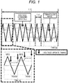
- update timing of the sinusoidal modulation signal is set to twice of "ridge” and “trough” of the carrier signal of the triangular wave so that no electromagnetic noise due to the frequency fc of the carrier signal occurs (see FIG. 1 ).
- ridge-trough update a three-phase voltage to be applied to an inverter needs to be updated at a frequency 2fc that is twice the carrier signal and a processing load of a microcomputer increases.
- the frequency of the voltage update timing needs to be increased. Therefore, it is difficult to increase the frequency of the carrier signal of the inverter.
- the voltage update timing is set to only "ridge” (hereinafter abbreviated as ridge update)
- the three-phase voltage to be applied to the inverter can be updated at the frequency fc of the carrier signal and the processing load of a microcomputer decreases (see FIG. 2 ).
- ridge update since the number of times of the voltage update timing is halved in the ridge update, a harmonic voltage other than a basic waveform voltage increases as a waveform of an output voltage becomes coarser than the ridge-trough update.
- An object of the present invention is to reduce electromagnetic noise while reducing a calculation load of a microcomputer.
- an inverter drive device switches a first control mode, a second control mode, and a third control mode on the basis of vehicle speed information in a motor control device that controls a power converter that drives a polyphase motor by a PWM pulse signal based on a carrier signal
- the first control mode being for updating a command voltage signal to the power converter only on a ridge side or a trough side of the carrier signal
- the second control mode being for updating a command voltage signal to the power converter both on a ridge side and a trough side of the carrier signal
- the third control mode being for updating a command voltage signal to the power converter only once of ridge-trough-ridge or trough-ridge-trough of the carrier signal.
- electromagnetic noise can be reduced while a calculation load of a microcomputer is reduced.
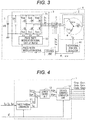
- FIG. 3 is a block diagram illustrating a configuration of a motor drive apparatus 6 including an inverter drive device according to the present embodiment.
- FIG. 4 is a block diagram of an inside of a control unit 1 illustrated in FIG. 3 .
- the motor drive apparatus 6 includes a motor 2 and an inverter 3.
- the inverter 3 includes an inverter circuit 31 that mutually converting a direct current into an alternating current, a pulse width modulation signal output means 32 that outputs a PWM signal to the inverter circuit 31, and a smoothing capacitor 33 that smooths direct current power.
- a high-voltage battery 5 is a direct current voltage source of the motor drive apparatus 6.
- a direct current voltage VB of the high-voltage battery 5 is converted into a pulsed three-phase alternating current voltage having a variable voltage and a variable frequency by the inverter circuit 31 and the pulse width modulation signal output means 32 of the inverter 3 and applied to the motor 2.
- the motor 2 is a synchronous motor rotationally driven by supplying the three-phase alternating current voltage.
- a rotational position sensor 4 is attached to the motor 2 in order to control a phase of an applied voltage of a three-phase alternating current according to a phase of an induced voltage of the motor 2, and a rotational position detector 41 calculates a rotational position ⁇ from an input signal of the rotational position sensor 4 and calculates a motor rotational speed ⁇ r.
- a resolver constituted by an iron core and winding is favorable.
- a magnetic resistance element such as a GMR sensor or a sensor using a Hall element is also acceptable.
- a current detection means 7 detects a U-phase alternating current Iu, a V-phase alternating current Iv and a W-phase alternating current Iw that are three-phase alternating currents flowing in the motor 2.
- the current detection means 7 provided with three current detectors is illustrated. However, two current detectors are provided and a remaining one phase may be calculated according to a fact that a sum of three-phase currents is zero.
- a pulsed direct current bus current flowing into the inverter 3 is detected as a voltage (current detection value Idc) between both ends of a shunt resistor Rsh inserted between the smoothing capacitor 33 and the inverter 3, and a direct current may be reproduced as a three-phase current according to the applied voltage.
- the control unit 1 includes a three-phase/dq conversion current control unit 11, a current control unit 12, and a voltage command generation unit 13, and drives the inverter circuit 31 of the inverter 3 according to the detected U-phase alternating current Iu, V-phase alternating current Iv, and W-phase alternating current Iw, and a d-axis current command Id* and a q-axis current command Iq* of the motor 2.
- the three-phase/dq conversion current control unit 11 calculates dq-converted d-axis current value Id and q-axis current value Iq from the detected U-phase alternating current Iu, V-phase alternating current Iv, W-phase alternating current Iw, and rotational position ⁇ .
- the current control unit 12 calculates a d-axis voltage command Vd* and a q-axis voltage command Vq* such that the d-axis current value Id and the q-axis current value Iq match the d-axis current command Id* and the q-axis current command Iq* created according to target torque.
- the voltage command generation unit 13 calculates a U-phase voltage command value Vu*, a V-phase voltage command value Vv*, and a UW-phase voltage command value Vw* that are three-phase voltage command values UVW-converted from the d-axis voltage command Vd*, the q-axis voltage command Vq*, and the rotational position ⁇ , and PWM-outputs a PWM pulse that is obtained by modulating a pulse width of the three-phase voltage command values.
- the PWM pulse controls ON/OFF of a semiconductor switch element of the inverter circuit 31 via a drive circuit to adjust an output voltage.
- the motor rotational speed ⁇ r is calculated from time change in the rotational position ⁇ , and a voltage command or a current command is created to coincide with a speed command from a host controller.
- the d-axis current command Id* and the q-axis current command Iq* are created using a relational expression or a map among the d-axis current value Id, the q-axis current value Iq, and motor torque.
- FIG. 5 is a block diagram of the voltage command generation unit 13.
- the voltage command generation unit 13 includes a voltage update timing generation unit 131, a dq/three-phase voltage command conversion unit 132, a triangular wave generation unit 133, and a gate signal generation unit 134.
- the voltage update timing generation unit 131 determines voltage update timing according to a calculation load of a microcomputer.
- FIG. 6 is a voltage update timing generation flow in the first embodiment.
- the voltage update timing generation unit 131 changes an update cycle T1 according to a processing load factor of the microcomputer on the basis of the voltage update timing generation flow in FIG. 6 .
- a processing load factor of the microcomputer varies according to the calculation load. For example, a case of using rectangular wave control or torque pulsation suppression control for improving a voltage utilization factor is dealt with.
- a frequency of a carrier signal is fc. In this case, since current estimation calculation or control in which 6-times pulsation is superimposed on dq-axis currents is performed, a calculation amount is increased as compared with normal current control.
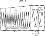
- FIGS. 7 to 9 illustrate the voltage update timings in the update cycle T1.
- a ratio between f1 and fc is 15 when a motor electrical angular frequency is f1 and the frequency of the carrier signal is fc.
- FIG. 7 illustrates the voltage update timing of when the update cycle T1 is 3/(2fc).
- the voltage update timing is 3/2 times the one cycle (1/fc) of the carrier signal, and "ridge side/trough side/ridge side” and “trough side/ridge side/trough side” of the carrier signal that is a triangular wave alternately appear.
- FIG. 8 illustrates the voltage update timing of when the update cycle T1 is 1/fc.
- the voltage update timing is one time the one cycle (1/fc) of the carrier signal, and "ridge side/trough side" of the carrier signal that is a triangular wave continuously appears.
- the above voltage update timing is abbreviated as update timing of "ridge”.
- FIG. 9 illustrates the voltage update timing of when the update cycle T1 is 1/(2fc).
- the voltage update timing is 1/2 times the one cycle (1/fc) of the carrier signal, and "ridge side” and “trough side” of the carrier signal that is a triangular wave alternately appear.
- the above voltage update timing is abbreviated as update timing of "ridge-trough”.
- the dq/three-phase voltage conversion unit 132 performs fixed coordinate conversion and two-phase three-phase conversion from the d-axis voltage command Vd* and the q-axis voltage command Vq* that are the outputs of the current control unit 12, the rotational position ⁇ that is the output of the rotational position detector 41, and the update cycle T1 that is the output of the voltage update timing generation unit 131 to generate a U-phase voltage command value Vu*, a V-phase voltage command value Vv*, and a W-phase voltage command value Vw*.
- the triangular wave generation unit 133 generates a triangular wave of the frequency fc of the carrier signal on the basis of the frequency fc of the carrier signal.
- the gate signal generation unit 134 compares the U-phase voltage command value Vu*, the V-phase voltage command value Vv*, and the W-phase voltage command value Vw* that are the outputs of the dq/three-phase voltage conversion unit 132 with the triangular wave that is the output of the triangular wave generation unit 133 to generate a pulsed voltage.
- gate signals Gup, Gvp, and Gwp of an upper arm are logically inverted to generate lower arm gate signals Gun, Gvn, and Gwn.
- the dq-axis voltage commands are calculated to the three-phase voltage commands, and the processing load of the microcomputer of the voltage command generation unit 13 to be compared with the triangular wave can be reduced.
- FIG. 10 is a graph illustrating harmonic components of a voltage caused by a difference in voltage update timing illustrated in FIGS. 7 to 9 of when a ratio of f1 and fc is 15, where a motor electrical angular frequency is f1 and a frequency of a carrier signal is fc.
- frequencies fc ⁇ 2f1 13th order component and 17th order component in FIG. 10
- fc ⁇ 4f1 11th order component and 19th order component in FIG. 10
- 2fc ⁇ f1 29th order component and 31st order component in FIG. 10
- Interference occurs between a rotating magnetic field of a stator and a magnetic field of a rotor due to the harmonic components of the voltage, resulting in occurrence of electromagnetic noise of frequencies fc ⁇ 3f1 and 2fc.
- FIG. 11 is a graph of a measurement result of noise of the motor 2 driven by the inverter drive device.
- the voltage update timing T1 of the voltage update timing generation unit 131 in this inverter drive device is (1/fc).
- the harmonic voltage output from the inverter 31 of the motor drive apparatus 6 is the harmonic voltage of when the voltage update timing T1 in FIG. 10 is (1/fc).
- the harmonic voltage of a frequency fc ⁇ f1 14th order component and 16th order component in FIG.
- the current becomes a harmonic current having the same frequency as the voltage.
- Interfere occurs between the rotating magnetic field of the stator and the magnetic field of the rotor due to the frequencies fc ⁇ 2f1 (13th order component and 17th order component in FIG. 10 ) and fc ⁇ 4f1 (11th order component and 19th order component of FIG. 10 ), resulting in occurrence of electromagnetic force of the frequency fc ⁇ 3f1.
- electromagnetic force of the frequencies fc ⁇ 3f1 and 2fc occurs. This electromagnetic force vibrates a motor case and a housing, resulting in the electromagnetic noise.
- the harmonic voltage of the frequency fc ⁇ f1 (14th order component and 16th order component in FIG. 10 ) does not occur. Therefore, frequencies of the electromagnetic force generated by the harmonic voltage are frequencies fc ⁇ 3f1 and 2fc. Further, when the voltage update timing T1 in FIG. 10 is (3/2fc), the harmonic voltage of the frequency fc ⁇ f1 (14th order component and 16th order component in FIG. 10 ) does not occur and the harmonic voltage of frequencies (2fc)/3 ⁇ f1 and (2fc)/3 ⁇ f1 occur. Therefore, electromagnetic noise of a frequency (2fc)/3 ⁇ 2f1 generated by the harmonic voltage occurs.
- the motor electrical angular frequency f1 changes accordingly.
- the frequency fc ⁇ 3f1 of the electromagnetic noise that changes according to the rotation speed of the motor, a natural frequency fm of a case housing (mechanism) of the motor 2, and a frequency caused by electromagnetic exciting force generated in proportion to the rotational speed inherent to the magnetic design of the motor 2 resonate, so that the noise becomes large.
- the noise of the frequency fc - 3f1 caused by the voltage harmonic of the inverter 3 coincides with the natural frequency fm of the motor structure system, and the noise becomes large due to the resonance .
- the noise due to the magnetic design of the motor occurs depending on the number of poles of the rotor and the number of slots of the stator of the motor, a magnetic gap, a winding method of the stator, and the like, and generally occurs at N times the motor electrical angular frequency f1. For example, in the measurement result of the motor in FIG. 11 , large noise occurs in the motor 2 at 12 times and 24 times the electrical angular frequency f1.
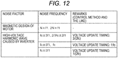
- FIG. 12 illustrates a table of frequencies of the electromagnetic noise generated by the motor 2 and the inverter 3.
- the electromagnetic force generated at these frequencies coincides with the natural frequency (fm1, fm2, fm3, or the like) of the case housing, vibration and noise due to the electromagnetic force become large.
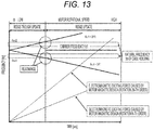
- voltage command update timing and a frequency of a carrier signal are changed to avoid the resonance to minimize the electromagnetic noise, unlike the actually measured electromagnetic noise illustrated in FIG. 11 .
- a calculation load of a microcomputer increases as the voltage command update timing is set to ridge-trough update while increasing the frequency of the carrier signal. Therefore, in a case of increasing the frequency of the carrier signal, the voltage command update timing needs to be set to ridge update.
- the carrier frequency coincides with natural frequencies fm1 and fm2 of the case housing as illustrated in FIG. 13 , and the carrier electromagnetic noise becomes large.
- FIG. 14 illustrates an example of a method of changing the carrier frequency and the voltage update timing according to the second embodiment of the present invention.
- two carrier frequencies a first carrier frequency fc1 and a second carrier frequency fc2 are provided.
- the carrier frequency is set to the carrier frequency rather than to the natural frequencies fm1 and fm2 of the case housing.
- the processing load of the microcomputer becomes high and the voltage update timing is set to the ridge update
- the carrier frequency fc1 is set to between the natural frequencies fm1 and fm2 of the case housing so as not to coincide with the frequency fc ⁇ 3f1 of the electromagnetic noise that radially spreads. With the setting, the resonance with the case housing is avoided, and the electromagnetic noise occurring in the motor drive system 6 can be reduced.
- the frequency fc2 of the carrier electromagnetic noise occurring as the voltage update timing is set to T1 may be caused to coincide with the natural frequency fm1 or fm2 of the case housing to generate sound with a small harmonic voltage.
- FIG. 15 is a configuration diagram of a hybrid automobile system to which the inverter drive device of the present embodiment is applied.
- the hybrid automobile system includes a power train in which the motor 2 is applied as a motor/generator.
- the reference numeral 700 represents a vehicle body.
- a front wheel axle 701 is rotatably supported on a front portion of the vehicle body 700, and front wheels 702 and 703 are provided at both ends of the front wheel axle 701.
- a rear wheel axle 704 is rotatably supported on a rear portion of the vehicle body 700, and rear wheels 705 and 706 are provided at both ends of the rear wheel axle 704.
- a differential gear 711 that is a power distribution mechanism is provided in a central portion of the front wheel axle 701 and distributes rotational driving force transmitted from an engine 710 via a transmission 712 to the right and left front wheel axles 701.
- a pulley 710a provided on a crankshaft of the engine 710 and a pulley 720a provided on a rotation shaft of the motor 2 are mechanically coupled via a belt 730 between the engine 710 and the motor 2.
- the rotational driving force of the motor 2 can be transmitted to the engine 710, and the rotational driving force of the engine 710 can be transmitted to the motor 2.
- the rotor rotates as three-phase alternating current power controlled by the inverter 3 is supplied to a stator coil of the stator, and the rotational driving force according to the three-phase alternating current power is generated.
- the motor 2 operates as an electric motor under the control of the inverter 3 while operating as a generator that generates the three-phase alternating current power when electromotive force is induced in the stator coil of the stator as the rotor rotates by receiving the rotational driving force of the engine 710.
- the inverter 3 is a power conversion device that converts the direct current power supplied from the high-voltage battery 5, which is a high-voltage (42 V or 300 V) system power supply, into the three-phase alternating current power, and controls the three-phase alternating current flowing in the stator coil of the motor 2 according to a magnetic pole position of the rotor according to an operation command value.
- the three-phase alternating current power generated by the motor 2 is converted into the direct current power by the inverter 3 to charge the high-voltage battery 5.
- the high-voltage battery 5 is electrically connected to a low-voltage battery 723 via a DC-DC converter 724.
- the low-voltage battery 723 constitutes a low-voltage (14 V) power supply of the automobile, and is used as a power supply for a starter 725 for initial start (cold start) of the engine 710, a radio, light, and the like.
- the inverter 3 drives the motor 2 to rotate the engine 710.
- the engine 710 is not stopped and the driving is continued.
- a drive source for auxiliary machinery that uses the engine 710 as a driving source such as an air conditioner compressor, needs to be secured.
- the auxiliary machine is driven by driving the motor 2.
- the motor 2 is driven to assist driving of the engine 710.
- the engine 710 causes the motor 2 to generate power to charge the high-voltage battery 5. That is, a regeneration mode at the time of braking or deceleration of the vehicle is performed.
- the electrically driven vehicle using the inverter drive device of the present embodiment reduces the electromagnetic noise while reducing the calculation load of the microcomputer, thereby reducing vibration-proof material, sound-proof material, and sound insulation material to be affixed to the vehicle body. Further, fuel economy can be improved by reducing these materials.
- the single inverter device has been described.
- the present invention can also be applied to a motor drive system in which an inverter unit and a motor are integrated as long as the system has the above-described functions.
Landscapes
- Engineering & Computer Science (AREA)
- Power Engineering (AREA)
- Inverter Devices (AREA)
- Control Of Ac Motors In General (AREA)
- Electric Propulsion And Braking For Vehicles (AREA)
Applications Claiming Priority (2)
| Application Number | Priority Date | Filing Date | Title |
|---|---|---|---|
| JP2016254647A JP6715759B2 (ja) | 2016-12-28 | 2016-12-28 | インバータ駆動装置およびそれを用いた電動車両システム |
| PCT/JP2017/040530 WO2018123291A1 (ja) | 2016-12-28 | 2017-11-10 | インバータ駆動装置およびそれを用いた電動車両システム |
Publications (3)
| Publication Number | Publication Date |
|---|---|
| EP3565102A1 true EP3565102A1 (de) | 2019-11-06 |
| EP3565102A4 EP3565102A4 (de) | 2020-07-08 |
| EP3565102B1 EP3565102B1 (de) | 2024-01-10 |
Family
ID=62707489
Family Applications (1)
| Application Number | Title | Priority Date | Filing Date |
|---|---|---|---|
| EP17886063.1A Active EP3565102B1 (de) | 2016-12-28 | 2017-11-10 | Wechselrichterantriebsvorrichtung und elektrisches fahrzeugsystem damit |
Country Status (5)
| Country | Link |
|---|---|
| US (1) | US10873285B2 (de) |
| EP (1) | EP3565102B1 (de) |
| JP (1) | JP6715759B2 (de) |
| CN (1) | CN110168905B (de) |
| WO (1) | WO2018123291A1 (de) |
Cited By (1)
| Publication number | Priority date | Publication date | Assignee | Title |
|---|---|---|---|---|
| EP3957512A4 (de) * | 2020-06-15 | 2022-06-01 | Jiangsu Contemporary Amperex Technology Limited | Verfahren und vorrichtung zur steuerung eines permanentmagnetmotors, stromversorgungssystem und elektrisches fahrzeug |
Families Citing this family (8)
| Publication number | Priority date | Publication date | Assignee | Title |
|---|---|---|---|---|
| KR102409013B1 (ko) * | 2018-10-30 | 2022-06-14 | 도시바 미쓰비시덴키 산교시스템 가부시키가이샤 | 전력 변환 장치 |
| JP7475936B2 (ja) * | 2020-04-03 | 2024-04-30 | 三菱重工サーマルシステムズ株式会社 | システム、車両、放電方法及びプログラム |
| JP7322808B2 (ja) * | 2020-05-20 | 2023-08-08 | 株式会社豊田自動織機 | インバータ制御装置及び車載用流体機械 |
| US11926220B2 (en) * | 2020-11-30 | 2024-03-12 | Mercedes-Benz Group AG | Hybrid transmission for a vehicle |
| US11912132B2 (en) | 2020-11-30 | 2024-02-27 | Mercedes-Benz Group AG | Hybrid transmission for a vehicle |
| DE102020007296B4 (de) | 2020-11-30 | 2025-03-27 | Mercedes-Benz Group AG | Hybridgetriebe für ein Fahrzeug |
| JP2022119590A (ja) * | 2021-02-04 | 2022-08-17 | ダイハツ工業株式会社 | インバータの制御装置 |
| WO2023073816A1 (ja) * | 2021-10-26 | 2023-05-04 | 日立Astemo株式会社 | モータ制御装置、モータ制御方法、ハイブリッドシステム、昇圧コンバータシステム、電動パワーステアリングシステム |
Family Cites Families (10)
| Publication number | Priority date | Publication date | Assignee | Title |
|---|---|---|---|---|
| WO2005034327A1 (ja) * | 2003-09-30 | 2005-04-14 | Mitsubishi Denki Kabushiki Kaisha | インバータ装置 |
| US7576500B2 (en) * | 2007-05-31 | 2009-08-18 | Gm Global Technology Operations, Inc. | Method and system for operating a motor to reduce noise in an electric vehicle |
| JP5320721B2 (ja) * | 2007-11-05 | 2013-10-23 | 株式会社安川電機 | Pwmインバータ装置 |
| JP5228460B2 (ja) * | 2007-12-03 | 2013-07-03 | パナソニック株式会社 | モータ制御装置 |
| JP4605274B2 (ja) * | 2008-08-27 | 2011-01-05 | トヨタ自動車株式会社 | 車両 |
| JP2011172303A (ja) | 2010-02-16 | 2011-09-01 | Toyota Motor Corp | インバータの制御装置およびインバータの制御方法 |
| WO2011148485A1 (ja) * | 2010-05-27 | 2011-12-01 | トヨタ自動車株式会社 | 電動機の制御装置および制御方法 |
| JP5505449B2 (ja) | 2012-04-06 | 2014-05-28 | 株式会社デンソー | 多相回転機の制御装置 |
| JP6003328B2 (ja) * | 2012-07-20 | 2016-10-05 | 株式会社豊田自動織機 | 回転電機のインバータ装置、及び、回転電機の駆動方法 |
| JP6179494B2 (ja) * | 2014-09-26 | 2017-08-16 | 株式会社デンソー | 交流電動機の制御装置 |
-
2016
- 2016-12-28 JP JP2016254647A patent/JP6715759B2/ja active Active
-
2017
- 2017-11-10 US US16/468,594 patent/US10873285B2/en active Active
- 2017-11-10 EP EP17886063.1A patent/EP3565102B1/de active Active
- 2017-11-10 WO PCT/JP2017/040530 patent/WO2018123291A1/ja not_active Ceased
- 2017-11-10 CN CN201780078451.9A patent/CN110168905B/zh active Active
Cited By (1)
| Publication number | Priority date | Publication date | Assignee | Title |
|---|---|---|---|---|
| EP3957512A4 (de) * | 2020-06-15 | 2022-06-01 | Jiangsu Contemporary Amperex Technology Limited | Verfahren und vorrichtung zur steuerung eines permanentmagnetmotors, stromversorgungssystem und elektrisches fahrzeug |
Also Published As
| Publication number | Publication date |
|---|---|
| JP2018107978A (ja) | 2018-07-05 |
| JP6715759B2 (ja) | 2020-07-01 |
| CN110168905A (zh) | 2019-08-23 |
| EP3565102A4 (de) | 2020-07-08 |
| CN110168905B (zh) | 2021-01-26 |
| US10873285B2 (en) | 2020-12-22 |
| WO2018123291A1 (ja) | 2018-07-05 |
| US20190334469A1 (en) | 2019-10-31 |
| EP3565102B1 (de) | 2024-01-10 |
Similar Documents
| Publication | Publication Date | Title |
|---|---|---|
| EP3565102B1 (de) | Wechselrichterantriebsvorrichtung und elektrisches fahrzeugsystem damit | |
| US12301071B2 (en) | Motor control device, mechatronic unit, power generation system, boost converter system, and electric vehicle system | |
| EP3758218B1 (de) | Motorsteuervorrichtung und elektrisches fahrzeugsystem damit | |
| CN112840556B (zh) | 电动机控制装置及电动车辆系统 | |
| US6486632B2 (en) | Control device for motor/generators | |
| CN105392660B (zh) | 逆变器装置及电动车辆 | |
| US12491774B2 (en) | Motor control device, electromechanical integrated unit, boost converter system, electric vehicle system, and motor control method | |
| US12074551B2 (en) | Motor control device, electromechanical unit, electric vehicle system, and motor control method | |
| US11984821B2 (en) | Inverter control device | |
| CN114846740B (zh) | 逆变器控制装置、电动车辆系统 | |
| US12562657B2 (en) | Inverter control device, hybrid system, electromechanical integrated unit, electric vehicle system, and inverter control method | |
| US12199539B2 (en) | Motor control device, electric vehicle, and motor control method | |
| CN118830188A (zh) | 马达控制装置、混合动力系统、机电一体单元、电动车辆系统 | |
| JP7727833B2 (ja) | モータ制御装置、モータ制御方法 | |
| US20250192711A1 (en) | Inverter Control Device, Electric Power Steering System, and Electric Vehicle System |
Legal Events
| Date | Code | Title | Description |
|---|---|---|---|
| STAA | Information on the status of an ep patent application or granted ep patent |
Free format text: STATUS: THE INTERNATIONAL PUBLICATION HAS BEEN MADE |
|
| PUAI | Public reference made under article 153(3) epc to a published international application that has entered the european phase |
Free format text: ORIGINAL CODE: 0009012 |
|
| STAA | Information on the status of an ep patent application or granted ep patent |
Free format text: STATUS: REQUEST FOR EXAMINATION WAS MADE |
|
| 17P | Request for examination filed |
Effective date: 20190605 |
|
| AK | Designated contracting states |
Kind code of ref document: A1 Designated state(s): AL AT BE BG CH CY CZ DE DK EE ES FI FR GB GR HR HU IE IS IT LI LT LU LV MC MK MT NL NO PL PT RO RS SE SI SK SM TR |
|
| AX | Request for extension of the european patent |
Extension state: BA ME |
|
| DAV | Request for validation of the european patent (deleted) | ||
| DAX | Request for extension of the european patent (deleted) | ||
| A4 | Supplementary search report drawn up and despatched |
Effective date: 20200609 |
|
| RIC1 | Information provided on ipc code assigned before grant |
Ipc: H02M 7/5395 20060101ALI20200604BHEP Ipc: H02M 7/48 20070101AFI20200604BHEP Ipc: H02M 1/00 20060101ALI20200604BHEP |
|
| STAA | Information on the status of an ep patent application or granted ep patent |
Free format text: STATUS: EXAMINATION IS IN PROGRESS |
|
| 17Q | First examination report despatched |
Effective date: 20210316 |
|
| RAP3 | Party data changed (applicant data changed or rights of an application transferred) |
Owner name: HITACHI ASTEMO, LTD. |
|
| GRAP | Despatch of communication of intention to grant a patent |
Free format text: ORIGINAL CODE: EPIDOSNIGR1 |
|
| STAA | Information on the status of an ep patent application or granted ep patent |
Free format text: STATUS: GRANT OF PATENT IS INTENDED |
|
| INTG | Intention to grant announced |
Effective date: 20230213 |
|
| GRAJ | Information related to disapproval of communication of intention to grant by the applicant or resumption of examination proceedings by the epo deleted |
Free format text: ORIGINAL CODE: EPIDOSDIGR1 |
|
| STAA | Information on the status of an ep patent application or granted ep patent |
Free format text: STATUS: EXAMINATION IS IN PROGRESS |
|
| GRAP | Despatch of communication of intention to grant a patent |
Free format text: ORIGINAL CODE: EPIDOSNIGR1 |
|
| INTC | Intention to grant announced (deleted) | ||
| STAA | Information on the status of an ep patent application or granted ep patent |
Free format text: STATUS: GRANT OF PATENT IS INTENDED |
|
| INTG | Intention to grant announced |
Effective date: 20230706 |
|
| GRAS | Grant fee paid |
Free format text: ORIGINAL CODE: EPIDOSNIGR3 |
|
| GRAA | (expected) grant |
Free format text: ORIGINAL CODE: 0009210 |
|
| STAA | Information on the status of an ep patent application or granted ep patent |
Free format text: STATUS: THE PATENT HAS BEEN GRANTED |
|
| AK | Designated contracting states |
Kind code of ref document: B1 Designated state(s): AL AT BE BG CH CY CZ DE DK EE ES FI FR GB GR HR HU IE IS IT LI LT LU LV MC MK MT NL NO PL PT RO RS SE SI SK SM TR |
|
| REG | Reference to a national code |
Ref country code: GB Ref legal event code: FG4D |
|
| REG | Reference to a national code |
Ref country code: CH Ref legal event code: EP |
|
| REG | Reference to a national code |
Ref country code: DE Ref legal event code: R096 Ref document number: 602017078451 Country of ref document: DE |
|
| REG | Reference to a national code |
Ref country code: IE Ref legal event code: FG4D |
|
| REG | Reference to a national code |
Ref country code: LT Ref legal event code: MG9D |
|
| REG | Reference to a national code |
Ref country code: NL Ref legal event code: MP Effective date: 20240110 |
|
| REG | Reference to a national code |
Ref country code: AT Ref legal event code: MK05 Ref document number: 1649664 Country of ref document: AT Kind code of ref document: T Effective date: 20240110 |
|
| PG25 | Lapsed in a contracting state [announced via postgrant information from national office to epo] |
Ref country code: NL Free format text: LAPSE BECAUSE OF FAILURE TO SUBMIT A TRANSLATION OF THE DESCRIPTION OR TO PAY THE FEE WITHIN THE PRESCRIBED TIME-LIMIT Effective date: 20240110 |
|
| PG25 | Lapsed in a contracting state [announced via postgrant information from national office to epo] |
Ref country code: NL Free format text: LAPSE BECAUSE OF FAILURE TO SUBMIT A TRANSLATION OF THE DESCRIPTION OR TO PAY THE FEE WITHIN THE PRESCRIBED TIME-LIMIT Effective date: 20240110 |
|
| PG25 | Lapsed in a contracting state [announced via postgrant information from national office to epo] |
Ref country code: IS Free format text: LAPSE BECAUSE OF FAILURE TO SUBMIT A TRANSLATION OF THE DESCRIPTION OR TO PAY THE FEE WITHIN THE PRESCRIBED TIME-LIMIT Effective date: 20240510 |
|
| PG25 | Lapsed in a contracting state [announced via postgrant information from national office to epo] |
Ref country code: LT Free format text: LAPSE BECAUSE OF FAILURE TO SUBMIT A TRANSLATION OF THE DESCRIPTION OR TO PAY THE FEE WITHIN THE PRESCRIBED TIME-LIMIT Effective date: 20240110 |
|
| PG25 | Lapsed in a contracting state [announced via postgrant information from national office to epo] |
Ref country code: GR Free format text: LAPSE BECAUSE OF FAILURE TO SUBMIT A TRANSLATION OF THE DESCRIPTION OR TO PAY THE FEE WITHIN THE PRESCRIBED TIME-LIMIT Effective date: 20240411 |
|
| PG25 | Lapsed in a contracting state [announced via postgrant information from national office to epo] |
Ref country code: RS Free format text: LAPSE BECAUSE OF FAILURE TO SUBMIT A TRANSLATION OF THE DESCRIPTION OR TO PAY THE FEE WITHIN THE PRESCRIBED TIME-LIMIT Effective date: 20240410 Ref country code: HR Free format text: LAPSE BECAUSE OF FAILURE TO SUBMIT A TRANSLATION OF THE DESCRIPTION OR TO PAY THE FEE WITHIN THE PRESCRIBED TIME-LIMIT Effective date: 20240110 |
|
| PG25 | Lapsed in a contracting state [announced via postgrant information from national office to epo] |
Ref country code: ES Free format text: LAPSE BECAUSE OF FAILURE TO SUBMIT A TRANSLATION OF THE DESCRIPTION OR TO PAY THE FEE WITHIN THE PRESCRIBED TIME-LIMIT Effective date: 20240110 |
|
| PG25 | Lapsed in a contracting state [announced via postgrant information from national office to epo] |
Ref country code: AT Free format text: LAPSE BECAUSE OF FAILURE TO SUBMIT A TRANSLATION OF THE DESCRIPTION OR TO PAY THE FEE WITHIN THE PRESCRIBED TIME-LIMIT Effective date: 20240110 |
|
| PG25 | Lapsed in a contracting state [announced via postgrant information from national office to epo] |
Ref country code: RS Free format text: LAPSE BECAUSE OF FAILURE TO SUBMIT A TRANSLATION OF THE DESCRIPTION OR TO PAY THE FEE WITHIN THE PRESCRIBED TIME-LIMIT Effective date: 20240410 Ref country code: NO Free format text: LAPSE BECAUSE OF FAILURE TO SUBMIT A TRANSLATION OF THE DESCRIPTION OR TO PAY THE FEE WITHIN THE PRESCRIBED TIME-LIMIT Effective date: 20240410 Ref country code: LT Free format text: LAPSE BECAUSE OF FAILURE TO SUBMIT A TRANSLATION OF THE DESCRIPTION OR TO PAY THE FEE WITHIN THE PRESCRIBED TIME-LIMIT Effective date: 20240110 Ref country code: IS Free format text: LAPSE BECAUSE OF FAILURE TO SUBMIT A TRANSLATION OF THE DESCRIPTION OR TO PAY THE FEE WITHIN THE PRESCRIBED TIME-LIMIT Effective date: 20240510 Ref country code: HR Free format text: LAPSE BECAUSE OF FAILURE TO SUBMIT A TRANSLATION OF THE DESCRIPTION OR TO PAY THE FEE WITHIN THE PRESCRIBED TIME-LIMIT Effective date: 20240110 Ref country code: GR Free format text: LAPSE BECAUSE OF FAILURE TO SUBMIT A TRANSLATION OF THE DESCRIPTION OR TO PAY THE FEE WITHIN THE PRESCRIBED TIME-LIMIT Effective date: 20240411 Ref country code: ES Free format text: LAPSE BECAUSE OF FAILURE TO SUBMIT A TRANSLATION OF THE DESCRIPTION OR TO PAY THE FEE WITHIN THE PRESCRIBED TIME-LIMIT Effective date: 20240110 Ref country code: BG Free format text: LAPSE BECAUSE OF FAILURE TO SUBMIT A TRANSLATION OF THE DESCRIPTION OR TO PAY THE FEE WITHIN THE PRESCRIBED TIME-LIMIT Effective date: 20240110 Ref country code: AT Free format text: LAPSE BECAUSE OF FAILURE TO SUBMIT A TRANSLATION OF THE DESCRIPTION OR TO PAY THE FEE WITHIN THE PRESCRIBED TIME-LIMIT Effective date: 20240110 |
|
| PG25 | Lapsed in a contracting state [announced via postgrant information from national office to epo] |
Ref country code: PL Free format text: LAPSE BECAUSE OF FAILURE TO SUBMIT A TRANSLATION OF THE DESCRIPTION OR TO PAY THE FEE WITHIN THE PRESCRIBED TIME-LIMIT Effective date: 20240110 Ref country code: PT Free format text: LAPSE BECAUSE OF FAILURE TO SUBMIT A TRANSLATION OF THE DESCRIPTION OR TO PAY THE FEE WITHIN THE PRESCRIBED TIME-LIMIT Effective date: 20240510 |
|
| PG25 | Lapsed in a contracting state [announced via postgrant information from national office to epo] |
Ref country code: SE Free format text: LAPSE BECAUSE OF FAILURE TO SUBMIT A TRANSLATION OF THE DESCRIPTION OR TO PAY THE FEE WITHIN THE PRESCRIBED TIME-LIMIT Effective date: 20240110 Ref country code: PT Free format text: LAPSE BECAUSE OF FAILURE TO SUBMIT A TRANSLATION OF THE DESCRIPTION OR TO PAY THE FEE WITHIN THE PRESCRIBED TIME-LIMIT Effective date: 20240510 Ref country code: PL Free format text: LAPSE BECAUSE OF FAILURE TO SUBMIT A TRANSLATION OF THE DESCRIPTION OR TO PAY THE FEE WITHIN THE PRESCRIBED TIME-LIMIT Effective date: 20240110 Ref country code: LV Free format text: LAPSE BECAUSE OF FAILURE TO SUBMIT A TRANSLATION OF THE DESCRIPTION OR TO PAY THE FEE WITHIN THE PRESCRIBED TIME-LIMIT Effective date: 20240110 |
|
| PG25 | Lapsed in a contracting state [announced via postgrant information from national office to epo] |
Ref country code: DK Free format text: LAPSE BECAUSE OF FAILURE TO SUBMIT A TRANSLATION OF THE DESCRIPTION OR TO PAY THE FEE WITHIN THE PRESCRIBED TIME-LIMIT Effective date: 20240110 |
|
| REG | Reference to a national code |
Ref country code: DE Ref legal event code: R097 Ref document number: 602017078451 Country of ref document: DE |
|
| PG25 | Lapsed in a contracting state [announced via postgrant information from national office to epo] |
Ref country code: SM Free format text: LAPSE BECAUSE OF FAILURE TO SUBMIT A TRANSLATION OF THE DESCRIPTION OR TO PAY THE FEE WITHIN THE PRESCRIBED TIME-LIMIT Effective date: 20240110 |
|
| PG25 | Lapsed in a contracting state [announced via postgrant information from national office to epo] |
Ref country code: EE Free format text: LAPSE BECAUSE OF FAILURE TO SUBMIT A TRANSLATION OF THE DESCRIPTION OR TO PAY THE FEE WITHIN THE PRESCRIBED TIME-LIMIT Effective date: 20240110 Ref country code: CZ Free format text: LAPSE BECAUSE OF FAILURE TO SUBMIT A TRANSLATION OF THE DESCRIPTION OR TO PAY THE FEE WITHIN THE PRESCRIBED TIME-LIMIT Effective date: 20240110 |
|
| PG25 | Lapsed in a contracting state [announced via postgrant information from national office to epo] |
Ref country code: SK Free format text: LAPSE BECAUSE OF FAILURE TO SUBMIT A TRANSLATION OF THE DESCRIPTION OR TO PAY THE FEE WITHIN THE PRESCRIBED TIME-LIMIT Effective date: 20240110 |
|
| PG25 | Lapsed in a contracting state [announced via postgrant information from national office to epo] |
Ref country code: SM Free format text: LAPSE BECAUSE OF FAILURE TO SUBMIT A TRANSLATION OF THE DESCRIPTION OR TO PAY THE FEE WITHIN THE PRESCRIBED TIME-LIMIT Effective date: 20240110 Ref country code: SK Free format text: LAPSE BECAUSE OF FAILURE TO SUBMIT A TRANSLATION OF THE DESCRIPTION OR TO PAY THE FEE WITHIN THE PRESCRIBED TIME-LIMIT Effective date: 20240110 Ref country code: RO Free format text: LAPSE BECAUSE OF FAILURE TO SUBMIT A TRANSLATION OF THE DESCRIPTION OR TO PAY THE FEE WITHIN THE PRESCRIBED TIME-LIMIT Effective date: 20240110 Ref country code: EE Free format text: LAPSE BECAUSE OF FAILURE TO SUBMIT A TRANSLATION OF THE DESCRIPTION OR TO PAY THE FEE WITHIN THE PRESCRIBED TIME-LIMIT Effective date: 20240110 Ref country code: DK Free format text: LAPSE BECAUSE OF FAILURE TO SUBMIT A TRANSLATION OF THE DESCRIPTION OR TO PAY THE FEE WITHIN THE PRESCRIBED TIME-LIMIT Effective date: 20240110 Ref country code: CZ Free format text: LAPSE BECAUSE OF FAILURE TO SUBMIT A TRANSLATION OF THE DESCRIPTION OR TO PAY THE FEE WITHIN THE PRESCRIBED TIME-LIMIT Effective date: 20240110 |
|
| PLBE | No opposition filed within time limit |
Free format text: ORIGINAL CODE: 0009261 |
|
| STAA | Information on the status of an ep patent application or granted ep patent |
Free format text: STATUS: NO OPPOSITION FILED WITHIN TIME LIMIT |
|
| PG25 | Lapsed in a contracting state [announced via postgrant information from national office to epo] |
Ref country code: IT Free format text: LAPSE BECAUSE OF FAILURE TO SUBMIT A TRANSLATION OF THE DESCRIPTION OR TO PAY THE FEE WITHIN THE PRESCRIBED TIME-LIMIT Effective date: 20240110 |
|
| 26N | No opposition filed |
Effective date: 20241011 |
|
| PG25 | Lapsed in a contracting state [announced via postgrant information from national office to epo] |
Ref country code: IT Free format text: LAPSE BECAUSE OF FAILURE TO SUBMIT A TRANSLATION OF THE DESCRIPTION OR TO PAY THE FEE WITHIN THE PRESCRIBED TIME-LIMIT Effective date: 20240110 |
|
| PG25 | Lapsed in a contracting state [announced via postgrant information from national office to epo] |
Ref country code: SI Free format text: LAPSE BECAUSE OF FAILURE TO SUBMIT A TRANSLATION OF THE DESCRIPTION OR TO PAY THE FEE WITHIN THE PRESCRIBED TIME-LIMIT Effective date: 20240110 |
|
| REG | Reference to a national code |
Ref country code: CH Ref legal event code: PL |
|
| PG25 | Lapsed in a contracting state [announced via postgrant information from national office to epo] |
Ref country code: MC Free format text: LAPSE BECAUSE OF FAILURE TO SUBMIT A TRANSLATION OF THE DESCRIPTION OR TO PAY THE FEE WITHIN THE PRESCRIBED TIME-LIMIT Effective date: 20240110 |
|
| PG25 | Lapsed in a contracting state [announced via postgrant information from national office to epo] |
Ref country code: LU Free format text: LAPSE BECAUSE OF NON-PAYMENT OF DUE FEES Effective date: 20241110 |
|
| REG | Reference to a national code |
Ref country code: CH Ref legal event code: PL |
|
| GBPC | Gb: european patent ceased through non-payment of renewal fee |
Effective date: 20241110 |
|
| PG25 | Lapsed in a contracting state [announced via postgrant information from national office to epo] |
Ref country code: CH Free format text: LAPSE BECAUSE OF NON-PAYMENT OF DUE FEES Effective date: 20241130 |
|
| REG | Reference to a national code |
Ref country code: BE Ref legal event code: MM Effective date: 20241130 |
|
| PG25 | Lapsed in a contracting state [announced via postgrant information from national office to epo] |
Ref country code: FI Free format text: LAPSE BECAUSE OF FAILURE TO SUBMIT A TRANSLATION OF THE DESCRIPTION OR TO PAY THE FEE WITHIN THE PRESCRIBED TIME-LIMIT Effective date: 20240110 |
|
| PG25 | Lapsed in a contracting state [announced via postgrant information from national office to epo] |
Ref country code: GB Free format text: LAPSE BECAUSE OF NON-PAYMENT OF DUE FEES Effective date: 20241110 Ref country code: BE Free format text: LAPSE BECAUSE OF NON-PAYMENT OF DUE FEES Effective date: 20241130 |
|
| PG25 | Lapsed in a contracting state [announced via postgrant information from national office to epo] |
Ref country code: FR Free format text: LAPSE BECAUSE OF NON-PAYMENT OF DUE FEES Effective date: 20241130 |
|
| PG25 | Lapsed in a contracting state [announced via postgrant information from national office to epo] |
Ref country code: IE Free format text: LAPSE BECAUSE OF NON-PAYMENT OF DUE FEES Effective date: 20241110 |
|
| PGFP | Annual fee paid to national office [announced via postgrant information from national office to epo] |
Ref country code: DE Payment date: 20250930 Year of fee payment: 9 |
|
| PG25 | Lapsed in a contracting state [announced via postgrant information from national office to epo] |
Ref country code: HU Free format text: LAPSE BECAUSE OF FAILURE TO SUBMIT A TRANSLATION OF THE DESCRIPTION OR TO PAY THE FEE WITHIN THE PRESCRIBED TIME-LIMIT; INVALID AB INITIO Effective date: 20171110 |
|
| PG25 | Lapsed in a contracting state [announced via postgrant information from national office to epo] |
Ref country code: CY Free format text: LAPSE BECAUSE OF FAILURE TO SUBMIT A TRANSLATION OF THE DESCRIPTION OR TO PAY THE FEE WITHIN THE PRESCRIBED TIME-LIMIT; INVALID AB INITIO Effective date: 20171110 |