EP3565186A1 - Vorrichtung und netzwerk zur zuverlässigen kommunikation in einem netzwerk - Google Patents
Vorrichtung und netzwerk zur zuverlässigen kommunikation in einem netzwerk Download PDFInfo
- Publication number
- EP3565186A1 EP3565186A1 EP18170412.3A EP18170412A EP3565186A1 EP 3565186 A1 EP3565186 A1 EP 3565186A1 EP 18170412 A EP18170412 A EP 18170412A EP 3565186 A1 EP3565186 A1 EP 3565186A1
- Authority
- EP
- European Patent Office
- Prior art keywords
- com
- module
- mon
- network device
- self
- Prior art date
- Legal status (The legal status is an assumption and is not a legal conclusion. Google has not performed a legal analysis and makes no representation as to the accuracy of the status listed.)
- Granted
Links
Images




Classifications
-
- H—ELECTRICITY
- H04—ELECTRIC COMMUNICATION TECHNIQUE
- H04L—TRANSMISSION OF DIGITAL INFORMATION, e.g. TELEGRAPHIC COMMUNICATION
- H04L1/00—Arrangements for detecting or preventing errors in the information received
- H04L1/24—Testing correct operation
-
- H—ELECTRICITY
- H04—ELECTRIC COMMUNICATION TECHNIQUE
- H04L—TRANSMISSION OF DIGITAL INFORMATION, e.g. TELEGRAPHIC COMMUNICATION
- H04L43/00—Arrangements for monitoring or testing data switching networks
- H04L43/08—Monitoring or testing based on specific metrics, e.g. QoS, energy consumption or environmental parameters
- H04L43/0805—Monitoring or testing based on specific metrics, e.g. QoS, energy consumption or environmental parameters by checking availability
- H04L43/0817—Monitoring or testing based on specific metrics, e.g. QoS, energy consumption or environmental parameters by checking availability by checking functioning
-
- H—ELECTRICITY
- H04—ELECTRIC COMMUNICATION TECHNIQUE
- H04L—TRANSMISSION OF DIGITAL INFORMATION, e.g. TELEGRAPHIC COMMUNICATION
- H04L43/00—Arrangements for monitoring or testing data switching networks
- H04L43/50—Testing arrangements
Definitions
- the invention relates to a self-checking network device for communication in a real-time network, wherein the self-checking network device is connected to two or more communication links, and the self-checking network device exchanges regular data and protocol data with other network devices and/or nodes of the real-time network using the two or more communication links, and said protocol data is communicated as part of one or more certain network protocols.
- the invention relates to a real-time network, in particular a real-time computer network, comprising at least one self-checking network device and one, two, or a multitude of nodes connected to said self-checking network device.
- the invention relates to distributed computer systems for use in safety-critical and/or safety-related applications.
- Example areas of such distributed computer systems are automotive in-vehicle distributed computer systems, avionics, industrial automation, in-vehicle distributed computer systems of duty vehicles, distributed computer systems for use in energy generation plants, industrial robotics, and many more.
- Such distributed computer systems must provide fault-tolerance capabilities, which means that they need to bring the application into a safe state in the case of failure (i.e., fail-safe systems).
- some distributed computer systems may even need to continue operation in case of failure (i.e., fail-operational systems).
- fail-safe systems are industrial automation systems
- examples of fail-operational systems are autonomously driving vehicles (e.g., cars, duty vehicles, drones, unmanned-aeronautical vehicles, airplanes, etc.).
- autonomously driving vehicles e.g., cars, duty vehicles, drones, unmanned-aeronautical vehicles, airplanes, etc.
- Often such distributed computer systems execute control algorithms that control the behavior of a physical system (like the movement of the car, airplane, duty vehicle, industrial robot, or the operation of the industrial automation system). Therefore, the distributed computer system must also provide real-time guarantees for computations as well as real-time guarantees for the communication between different subsystems of the distributed computer system.
- Distributed computer systems often realize network protocols to coordinate the activities of (some) of the subsystems of the distributed computer system, for example to satisfy the real-time communication requirements of the distributed computer system.
- a means to achieve fault-tolerance capabilities is the design of one, two, or a multitude of subsystems each as a self-checking pair.
- a self-checking pair can be constructed by two parts, a commander part COM and a monitor part MON, where the monitor MON monitors the inputs and outputs of the commander COM and has an ability to execute one, two, or a multitude of safe actions.
- a safe action may be the shutdown of the commander COM or the shutdown of the overall self-checking pair, the selective disablement of certain elements of the self-checking pair, the invalidation of some or all of the data produced by the commander COM, or similar actions.
- the self-checking network device comprises at least four modules, wherein the network device and/or each of the four modules is configured in a way that a first module of the at least four modules receives both regular data and protocol data from said communication links on a first input - COM-IN -, and said first module forwards protocol data on a second input - P-COM-IN - to a second module of the at least four modules, wherein said second module executes a first function as part of the one or the more certain network protocols, using protocol data received on said second input - P-COM-IN - and produces protocol data as output on a first output - P-COM-OUT -, and a third module of the at least four modules monitors said second input - P-COM-IN - and said first output - P-COM-OUT - of said second module, and wherein said third module executes protocol checks on said second input - P-COM-IN - and said first
- the object is achieved with a network mentioned above, where said network comprises one, two or more of said self-checking network devices is/are network devices according to the invention.
- a key design aspect is in the reduction of implementation complexity and therefore also cost reduction by separating state-of-the-art monolithic parts of self-checking pairs into modules.
- the commander part COM and the monitor part MON as modularized parts with at least two modules each: one module that handles regular dataflow and a second module that handles traffic specific to certain network protocols. This modularization simplifies the monitoring activity of the monitor MON and/or the coordination between the commander COM and the monitor MON.
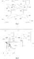
- Fig. 1 depicts an example of a real-time network.
- nodes 101 are connected to network devices 201, 202, 203 with communication links 110.
- Network devices 201, 202, 203 may be connected to each other as well.
- Network devices 201, 202, 203 may be switches, routers, gateways, starcouplers or alike.
- Nodes 101 may be sensors, actuators, and/or may comprise functionality to execute application code, as for example a control program.
- the communication links 110 are full-duplex, which means they allow communication in both directions at the same time.
- the communication links 110 may be Ethernet links.
- the communication links 110 may connect one, two, or many SERDES (serializer de-serializer) interfaces of the nodes 101 and network devices 201, 202, 203, for example to realize PCIe connections.
- SERDES serializer de-serializer
- Fig. 2 depicts another example of a real-time network.
- this real-time network nodes 101 connect to multiple network devices 201 via communication links 110, for example full-duplex links.
- communication links 110 for example full-duplex links.
- each node 101 can still communicate with each other node 101 by means of the non-faulty network devices 201 and non-faulty communication links 110.
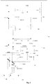
- Fig. 3 depicts an example of a network device 201 designed as self-checking pair with monolithic parts.
- the network device 201 presented implements a monolithic commander part COM and a monolithic monitor part MON.
- the network device 201 is connected to three communication links 110.
- the number of communication links 110 that a network device may connect to is two or higher than two.
- the full-duplex characteristic of the communication links 110 is depicted by two arrows connecting the communication link 110 to the network device.
- the arrow pointing from the communication link 110 to the network device 201 represents reception of data from a communication link 110 in the network device 201, while the arrow pointing from the network device to the communication link 110 represents the transmission of data from the network device 201 to the communication link 110.
- the network device 201 receives data from a communication link 110.
- the communication within the network device 201 and the communication of the network device 201 with the communication links is represented via connections that may act as inputs, as outputs, or both (e.g., the output of one part may be the input to another part).
- Both, the commander part COM (via the input COM-IN) as well as the monitor part MON (via the input MON-IN1) receive some or all of said data. Branches from the reception/transmission lines are symbolically depicted by black dots in the figures). A subset of said data received may belong to certain network protocols that both the commander part COM and the monitor part MON process by means of protocol units C-PU and M-PU.
- Protocol data For example, in the case of the SAE AS6802 Compression Master, the C-PU and M-PU would receive so called Protocol Control Frames (PCFs) from the communication links and generate new Compressed Protocol Control Frames (compressed PCFs).
- PCFs Protocol Control Frames
- Protocol data that belongs to said certain network protocols is provided to the protocol units C-PU and M-PU by means of interfaces C-INT and M-INT1, respectively.
- Data that does not belong to said certain network protocols is not processed by the protocol units C-PU and M-PU and is not provided to the protocol units C-PU and M-PU by means of the respective interfaces C-INT and M-INT1.
- regular data may also include data from network protocols other than the said certain network protocols that are executed in the protocol units C-PU and M-PU.
- the commander part COM of the network device 201 executes one, two, or multiple of regular operations C-SW on regular data, examples of such regular operations are:
- a synchronized timebase used for regular data transmission is established by means of a clock synchronization protocol that belongs to the set of said certain network protocols.
- the certain network protocol used is the SAE AS6802 clock synchronization protocol.
- the certain network protocol is the IEEE 802.1AS protocol.
- the certain network protocol is the IEEE 1588 protocol.
- the monitor part MON of the network device 201 listens to some or all of the data that the commander part COM receives (via the input MON-IN1) as well as to all or some of the data that the commander part COM transmits (via input MON-IN2). As depicted output COM-OUT acts as the input MON-IN2.
- the monitor part MON furthermore, executes one or many checks M-CHK that aim to identify whether the output COM-OUT generated by the commander part COM is a correct response to the input COM-IN of the commander part COM. If said one or many checks M-CHK indicate that the COM-OUT is not a correct response to the input COM-IN, then the monitor part MON may execute a safe action SA. In Fig.
- the safe action SA is represented by an output interception mechanism CUT that transforms data communicated on the output COM-OUT of the commander part COM to different data communicated on output COM-MON-OUT.
- This different data on output COM-MON-OUT may be of the nature that any receiver of data on said output can identify the data on the output as incorrect.
- Other safe actions have already been mentioned earlier, but are not depicted here and may be executed in addition or as an alternative to the safe action SA depicted in Fig. 3 .
- the monitor part MON and the commander part COM may need to exchange information via an interface EXCH.
- This information may be for example information regarding the validity, correctness, contents, and/or timing of the received regular data and/or the received protocol data.
- Fig. 3 also shows an example of an inner structure of the monitor part MON.
- the monitor part MON would receive the input COM-IN as input MON-IN1 in a unit M-SW that executes the same or similar regular operations C-SW as the commander part COM.
- This unit M-SW provides the results of said same or similar regular operations via an interface M-INT2 as input for the check(s) M-CHK.
- certain protocol data may be provided to the protocol unit M-PU of the monitor part MON.
- the protocol unit M-PU may as well provide input for said check(s) via an interface M-INT3.
- the commander part COM and the monitor part MON are monolithic parts. That means that the check or checks M-CHK executed by the monitor part MON address both, regular data and protocol data.
- This monolithic design has two major drawbacks:
- Fig. 4 depicts an example realization of a network device 201 that removes said drawbacks by a modularized design of a commander part COM into at least two modules S-COM and P-COM and a monitor part MON into at least two modules S-MON and P-MON such that the check or checks M-CHK are separated in a check or set of checks P-CHK that the monitor part MON executes for protocol data in the P-MON module and a check or set of checks S-CHK that the monitor part MON executes for regular data in the S-MON module.
- the check or set of checks P-CHK does/do not need to be executed for each communication link 110 that the network device connects 201 to, but need to be executed less than the number of communication links 110 that the network device connects to.
- the check or set of checks P-CHK does/do need to be executed only for one set of input P-COM-IN and output P-COM-OUT.
- the check or set of checks S-CHK for regular data may still be executed for each communication link 110.
- the same check or set of checks S-CHK executed for regular data may also be executed for protocol data.
- the communication between modules of the network device 201 is represented via connections that may act as inputs, as outputs, or both (e.g., the output of one module may be the input to another module).
- Checks on protocol data P-CHK may be for example: the P-MON may check that the P-COM only generates protocol data on its output P-COM-OUT that corresponds to the rules of said certain network protocols. This check or set of checks P-CHK may allow for certain inaccuracies that result from physical effects such as the imperfection of synchronization of the P-COM to the P-MON.
- Rules may be deduced from the specifications and/or standards of said certain network protocols and/or from manual review of concrete implementations of said certain network protocols.
- An example of said rules is for example the compression master algorithm as defined in the SAE AS6802 standard that defines how a compressed PCF is generated from one or many input PCFs.
- the P-COM would calculate the compressed PCF and provide this compressed PCF on its output P-COM-OUT and the P-MON module would check whether the compressed PCF as produced from the P-COM module satisfies the rules derived from the compression master algorithm of the SAE AS6802 standard.
- the check P-CHK for rules and algorithms of certain network protocols may include the check that certain specific protocol data is produced, e.g., specific protocol message with specific types and contents.
- the P-CHK may include checks that the P-COM only produces Coldstart Frames and/or Coldstart Acknowledge Frames and/or Integration frames at particular points in time with particular content. Similar protocol checks P-CHK are possible for other synchronization protocols, security protocols, and/or real-time protocols. For example in the case of IEEE 1588 or IEEE 802.1AS a protocol check P-CHK could check that announce or synchronization messages and/or delay messages and/or delay response messages may only be sent at particular points in time with particular content.
- Protocol execution typically requires the P-MON to execute the certain network protocol(s) (or in some cases simplified versions of it/ them) in coordination with the C-MON module and is therefore (because of the duplicated execution and the need for coordination P-EXCH) costly and complex to implement.
- Protocol execution is indicated by C-PU and M-PU in the P-COM and P-MON modules respectively.
- the protocol execution M-PU in the P-MON module provides information for the protocol check(s) P-CHK by means of an interface M-INT5.
- S-CHK Regular data checks S-CHK may be for example:
- Fig. 4 further depicts a separation of the information exchange EXCH between the commander part COM and the monitor part MON in a first information exchange P-EXCH between the P-COM module and the P-MON module and a second information exchange S-EXCH between the S-COM module and the S-MON module.
- P-EXCH protocol checks
- S-EXCH second information exchange between the S-COM module and the S-MON module.
- Fig. 4 further depicts that because of the modularization the internal interface C-INT in the monolithic design of the commander part COM ( Fig. 3 ) is replaced by an interface between the S-COM and P-COM modules.
- this interface between the modules S-COM and P-COM consists of
- the P-MON module applies the safe action P-SA when the protocol check or set of checks P-CHK indicates a faulty behavior of the P-COM module.
- the P-MON module receives part of or all protocol data that the P-COM module receives (by monitoring the input P-MON-IN1) and that the P-COM module produces (by monitoring the input P-MON-IN2 that branches from the output P-COM-OUT).
- the S-MON module does not execute protocol checks, but only executes checks S-CHK on regular data and may also execute the same regular data checks on the protocol data as well.
- One realization of this application of the same regular data checks S-CHK on protocol data is depicted in Fig. 4 which indicates these same checks as for regular data also on the protocol data by additional inputs to S-MON: MON-IN2a and MON-IN1a.
- Input MON-IN2a branches from P-COM-IN, which is an input to P-COM as well as an output from S-COM.
- Input MON-IN1a branches from P-COM-MON-OUT which is an input to S-COM and originates as output from P-COM subject to modification by P-CUT.
- the S-MON can implement regular data checks S-CHK on this protocol data by monitoring the output behavior of the S-COM on the output COM-OUT.
- the S-COM in the case of a failure, sends out protocol data on an output COM-OUT that it did not receive prior from the input P-COM-MON-OUT, the S-CHK in the S-MON would detect this faulty behavior by the previously mentioned regular data check:
- Fig. 4a depicts another realization of the invention that slightly extends the realization as discussed in Fig. 4 .
- the realization in Fig. 4a also implements an output interception mechanism CUT on P-COM-IN.
- P-COM-IN is an output from S-COM acting as input to P-COM.
- the S-MON may initiate a safe action SA that activates the interception mechanism CUT on P-COM-IN.
- Fig. 5 depicts another example realization of the modularization of the commander part COM and the monitor part MON.
- the network device 201 is realized by two encapsulated devices P201 and S201.
- the modules P-COM and P-MON as well as the respective safety actions P-SA and P-CUT are encapsulated in an encapsulated device P201, while the remaining modules S-COM and S-MON as well as the safety actions SA and CUT are encapsulated in another encapsulated device.
- the two encapsulated devices P201 and S201 are connected to each other by means of an encapsulation link 110a.
- this encapsulation link 110a may be a communication link 110.
- the encapsulation link 110a may also differ from the communication links 110 in the network, for example it may be realized by communication speeds, communication protocol, physical characteristics, etc. that differ from the ones used by the communication links 110.
- Fig. 6 depicts another realization of the modularization of the commander part COM and the monitor part MON.
- the network device 201 is realized by two encapsulated devices P201 and S201.
- the two encapsulated devices P201 and S201 are connected by two encapsulation links 110a.
- the protocol data checks P-CHK, the protocol safety actions P-SA, and the interception mechanism P-CUT is implemented outside the P-MON module as part of the encapsulated device S201.
- the protocol data checks P-CHK, the protocol safety actions P-SA, and the interception mechanism P-CUT may be realized together by means of a compare action P-COMPARE that takes as input P-COM-OUT which is output of the P-COM module and takes as an input P-MON-OUT which is output of the P-MON module and generates the output P-COM-MON-OUT which is input to the S-COM module.
- the data communicated on P-COM-MON-OUT may be equal to the data communicated on P-COM-OUT if the protocol checks P-CHK indicate that data communicated on P-COM-OUT is correct.
- Fig. 7 depicts another realization of the modularization of the commander part COM and the monitor part MON.
- the network device 201 is realized by two encapsulated devices P201 and S201.
- the P-MON module in the encapsulated device P201 does not take as input a branched signal from the P-COM-IN, but receives its input directly from the S-COM module via P-MON-IN.
- Both P-MON-IN and P-MON-OUT are communicated by means of an encapsulation link 110a.
Landscapes
- Engineering & Computer Science (AREA)
- Computer Networks & Wireless Communication (AREA)
- Signal Processing (AREA)
- Environmental & Geological Engineering (AREA)
- Data Exchanges In Wide-Area Networks (AREA)
- Small-Scale Networks (AREA)
Priority Applications (2)
| Application Number | Priority Date | Filing Date | Title |
|---|---|---|---|
| EP18170412.3A EP3565186B1 (de) | 2018-05-02 | 2018-05-02 | Vorrichtung und netzwerk zur zuverlässigen kommunikation in einem netzwerk |
| US16/399,087 US10868745B2 (en) | 2018-05-02 | 2019-04-30 | Device and network to reliably communicate in a network |
Applications Claiming Priority (1)
| Application Number | Priority Date | Filing Date | Title |
|---|---|---|---|
| EP18170412.3A EP3565186B1 (de) | 2018-05-02 | 2018-05-02 | Vorrichtung und netzwerk zur zuverlässigen kommunikation in einem netzwerk |
Publications (2)
| Publication Number | Publication Date |
|---|---|
| EP3565186A1 true EP3565186A1 (de) | 2019-11-06 |
| EP3565186B1 EP3565186B1 (de) | 2021-06-30 |
Family
ID=62200232
Family Applications (1)
| Application Number | Title | Priority Date | Filing Date |
|---|---|---|---|
| EP18170412.3A Active EP3565186B1 (de) | 2018-05-02 | 2018-05-02 | Vorrichtung und netzwerk zur zuverlässigen kommunikation in einem netzwerk |
Country Status (2)
| Country | Link |
|---|---|
| US (1) | US10868745B2 (de) |
| EP (1) | EP3565186B1 (de) |
Families Citing this family (1)
| Publication number | Priority date | Publication date | Assignee | Title |
|---|---|---|---|---|
| EP3565186B1 (de) * | 2018-05-02 | 2021-06-30 | TTTech Computertechnik AG | Vorrichtung und netzwerk zur zuverlässigen kommunikation in einem netzwerk |
Citations (2)
| Publication number | Priority date | Publication date | Assignee | Title |
|---|---|---|---|---|
| EP2139172A1 (de) * | 2008-06-25 | 2009-12-30 | Honeywell International Inc. | Hybride Topolgie-Ethernet-Architektur |
| EP3166246A1 (de) * | 2015-11-06 | 2017-05-10 | Fts Computertechnik Gmbh | Verfahren zum nachweisen und handhaben von fehlern bei der kommunikation in einem rechnernetzwerk |
Family Cites Families (20)
| Publication number | Priority date | Publication date | Assignee | Title |
|---|---|---|---|---|
| US4070648A (en) * | 1976-06-18 | 1978-01-24 | Ncr Corporation | Computer to computer communication system |
| US5533034A (en) * | 1992-06-26 | 1996-07-02 | Matsushita Electric Industrial Co., Ltd. | High speed data transfer device having improved efficiency |
| US6151689A (en) * | 1992-12-17 | 2000-11-21 | Tandem Computers Incorporated | Detecting and isolating errors occurring in data communication in a multiple processor system |
| US5854994A (en) * | 1996-08-23 | 1998-12-29 | Csi Technology, Inc. | Vibration monitor and transmission system |
| KR100433908B1 (ko) * | 2001-10-29 | 2004-06-04 | 삼성전자주식회사 | 통신시스템의 오류 검출 정보 송수신 장치 및 방법 |
| JP3757857B2 (ja) * | 2001-12-12 | 2006-03-22 | ソニー株式会社 | データ通信システム、データ送信装置、データ受信装置、および方法、並びにコンピュータ・プログラム |
| EP1504429A4 (de) * | 2002-05-07 | 2006-05-03 | Argo Tech Corp | Verfolgungssystem und zugeordnetes verfahren |
| US8060774B2 (en) * | 2005-06-24 | 2011-11-15 | Google Inc. | Memory systems and memory modules |
| DE102005062575B4 (de) * | 2005-12-27 | 2009-02-12 | Oce Printing Systems Gmbh | Verfahren und Vorrichtung zum Übertragen von Daten über eine Datenverbindung von einem Sender zu einem Empfänger mittels Pakete |
| US20080195912A1 (en) * | 2007-02-14 | 2008-08-14 | Nokia Corporation | Method of communicatoin |
| WO2009141860A1 (ja) * | 2008-05-19 | 2009-11-26 | 富士通株式会社 | 検証装置、検証方法および検証プログラム |
| JP4985565B2 (ja) * | 2008-06-30 | 2012-07-25 | 富士通株式会社 | 送受信回路、受信回路及び送受信回路の制御方法 |
| US9298529B2 (en) * | 2014-05-29 | 2016-03-29 | Freescale Semiconductor, Inc. | Indicating internal transmitter errors in a controller area network (CAN) |
| WO2016033629A2 (de) * | 2014-09-05 | 2016-03-10 | Fts Computertechnik Gmbh | Computersystem und verfahren für sicherheitskritische anwendungen |
| WO2016049670A1 (de) * | 2014-10-01 | 2016-04-07 | Fts Computertechnik Gmbh | Verteiltes echtzeitcomputersystem und zeitgesteuerte verteilereinheit |
| EP3110061B1 (de) * | 2015-06-23 | 2020-03-11 | TTTech Auto AG | Verteiltes echtzeitcomputersystem sowie verfahren zur erzwingung des fail-silent-verhaltens eines verteilten echtzeitcomputersystems |
| US10324797B2 (en) * | 2016-02-26 | 2019-06-18 | Tttech Auto Ag | Fault-tolerant system architecture for the control of a physical system, in particular a machine or a motor vehicle |
| DE102017101545B4 (de) * | 2017-01-26 | 2025-01-30 | Infineon Technologies Ag | Sensorsteuereinheit, Sensorsignalempfänger, ein Modul mit inkrementellem, magnetischem Geschwindigkeitssensor, ein Verfahren für eine Sensorsteuereinheit, ein Verfahren für einen Sensorsignalempfänger und Computerprogramm |
| EP3376330B1 (de) * | 2017-03-17 | 2020-11-04 | TTTech Auto AG | Fehlertolerantes verfahren zur erkennung von fehlern in einem elektronischen system zur steuerung eines kontrollierten objektes |
| EP3565186B1 (de) * | 2018-05-02 | 2021-06-30 | TTTech Computertechnik AG | Vorrichtung und netzwerk zur zuverlässigen kommunikation in einem netzwerk |
-
2018
- 2018-05-02 EP EP18170412.3A patent/EP3565186B1/de active Active
-
2019
- 2019-04-30 US US16/399,087 patent/US10868745B2/en active Active
Patent Citations (2)
| Publication number | Priority date | Publication date | Assignee | Title |
|---|---|---|---|---|
| EP2139172A1 (de) * | 2008-06-25 | 2009-12-30 | Honeywell International Inc. | Hybride Topolgie-Ethernet-Architektur |
| EP3166246A1 (de) * | 2015-11-06 | 2017-05-10 | Fts Computertechnik Gmbh | Verfahren zum nachweisen und handhaben von fehlern bei der kommunikation in einem rechnernetzwerk |
Also Published As
| Publication number | Publication date |
|---|---|
| EP3565186B1 (de) | 2021-06-30 |
| US10868745B2 (en) | 2020-12-15 |
| US20190342196A1 (en) | 2019-11-07 |
Similar Documents
| Publication | Publication Date | Title |
|---|---|---|
| US11016463B2 (en) | Control and data-transfer system, gateway module, I/O module, and method for process control | |
| US8228946B2 (en) | Method for fail-safe communication | |
| US8812759B2 (en) | Bus subscriber device for connection to a line-redundant data bus, and method for controlling the communication of a bus subscriber with a line-redundant serial data bus | |
| US10686732B2 (en) | Method and control device for transmitting safety-relevant data in a motor vehicle by means of an ethernet standard | |
| US10523462B2 (en) | Communication network for transmission of messages | |
| US20070242614A1 (en) | Data transfer method and automation system used in said data transfer method | |
| US20130315362A1 (en) | Nuclear digital instrumentation and control system | |
| US11927950B2 (en) | System and method of communicating safety data over high availability industrial control systems | |
| US20210359876A1 (en) | Managed Switch With Physically Distributed Ports | |
| EP2656581B1 (de) | Netzkoppelvorrichtung und übertragungsverfahren für paketbasierte datennetzwerke in prozessleitsystemen oder betriebsleitsystemen | |
| US10397081B2 (en) | Distributed real-time computer system and method for forcing fail-silent behavior of a distributed real-time computer system | |
| US10868745B2 (en) | Device and network to reliably communicate in a network | |
| US8959386B2 (en) | Network and expansion unit and method for operating a network | |
| US20230053889A1 (en) | Communication method, communication device and communication system | |
| EP2784988A1 (de) | Kommunikationsschnittstellenmodul für ein modulares Steuerungsgerät eines industriellen Automatisierungssystems | |
| CN114536322B (zh) | 机器人控制柜以及机器人系统 | |
| Alanen et al. | Safety of digital communications in machines | |
| KR20170089209A (ko) | 분산처리 연동시스템에서 소프트웨어 안전성 구현방법 | |
| RU2430400C1 (ru) | Комплекс резервируемых программно-аппаратных средств автоматизации контроля и управления | |
| Paulitsch et al. | FlexRay in aerospace and safety-sensitive systems | |
| KR101417402B1 (ko) | 차량 네트워크에서의 게이트웨이 오류 대처 장치 및 그 방법 | |
| TWI646802B (zh) | Battery system control network and reset method thereof | |
| US6934882B2 (en) | Method and device to transmit data | |
| Pradeep et al. | Comparison of CAN and flexray protocol for automotive application | |
| Seo et al. | A reliable gateway for in-vehicle networks |
Legal Events
| Date | Code | Title | Description |
|---|---|---|---|
| PUAI | Public reference made under article 153(3) epc to a published international application that has entered the european phase |
Free format text: ORIGINAL CODE: 0009012 |
|
| STAA | Information on the status of an ep patent application or granted ep patent |
Free format text: STATUS: THE APPLICATION HAS BEEN PUBLISHED |
|
| AK | Designated contracting states |
Kind code of ref document: A1 Designated state(s): AL AT BE BG CH CY CZ DE DK EE ES FI FR GB GR HR HU IE IS IT LI LT LU LV MC MK MT NL NO PL PT RO RS SE SI SK SM TR |
|
| AX | Request for extension of the european patent |
Extension state: BA ME |
|
| STAA | Information on the status of an ep patent application or granted ep patent |
Free format text: STATUS: REQUEST FOR EXAMINATION WAS MADE |
|
| 17P | Request for examination filed |
Effective date: 20200428 |
|
| RBV | Designated contracting states (corrected) |
Designated state(s): AL AT BE BG CH CY CZ DE DK EE ES FI FR GB GR HR HU IE IS IT LI LT LU LV MC MK MT NL NO PL PT RO RS SE SI SK SM TR |
|
| GRAP | Despatch of communication of intention to grant a patent |
Free format text: ORIGINAL CODE: EPIDOSNIGR1 |
|
| STAA | Information on the status of an ep patent application or granted ep patent |
Free format text: STATUS: GRANT OF PATENT IS INTENDED |
|
| INTG | Intention to grant announced |
Effective date: 20210118 |
|
| GRAS | Grant fee paid |
Free format text: ORIGINAL CODE: EPIDOSNIGR3 |
|
| GRAA | (expected) grant |
Free format text: ORIGINAL CODE: 0009210 |
|
| STAA | Information on the status of an ep patent application or granted ep patent |
Free format text: STATUS: THE PATENT HAS BEEN GRANTED |
|
| AK | Designated contracting states |
Kind code of ref document: B1 Designated state(s): AL AT BE BG CH CY CZ DE DK EE ES FI FR GB GR HR HU IE IS IT LI LT LU LV MC MK MT NL NO PL PT RO RS SE SI SK SM TR |
|
| REG | Reference to a national code |
Ref country code: CH Ref legal event code: EP |
|
| REG | Reference to a national code |
Ref country code: AT Ref legal event code: REF Ref document number: 1407400 Country of ref document: AT Kind code of ref document: T Effective date: 20210715 |
|
| REG | Reference to a national code |
Ref country code: DE Ref legal event code: R096 Ref document number: 602018019190 Country of ref document: DE |
|
| REG | Reference to a national code |
Ref country code: IE Ref legal event code: FG4D |
|
| REG | Reference to a national code |
Ref country code: LT Ref legal event code: MG9D |
|
| PG25 | Lapsed in a contracting state [announced via postgrant information from national office to epo] |
Ref country code: FI Free format text: LAPSE BECAUSE OF FAILURE TO SUBMIT A TRANSLATION OF THE DESCRIPTION OR TO PAY THE FEE WITHIN THE PRESCRIBED TIME-LIMIT Effective date: 20210630 Ref country code: HR Free format text: LAPSE BECAUSE OF FAILURE TO SUBMIT A TRANSLATION OF THE DESCRIPTION OR TO PAY THE FEE WITHIN THE PRESCRIBED TIME-LIMIT Effective date: 20210630 Ref country code: BG Free format text: LAPSE BECAUSE OF FAILURE TO SUBMIT A TRANSLATION OF THE DESCRIPTION OR TO PAY THE FEE WITHIN THE PRESCRIBED TIME-LIMIT Effective date: 20210930 |
|
| REG | Reference to a national code |
Ref country code: NL Ref legal event code: MP Effective date: 20210630 |
|
| REG | Reference to a national code |
Ref country code: AT Ref legal event code: MK05 Ref document number: 1407400 Country of ref document: AT Kind code of ref document: T Effective date: 20210630 |
|
| REG | Reference to a national code |
Ref country code: DE Ref legal event code: R079 Ref document number: 602018019190 Country of ref document: DE Free format text: PREVIOUS MAIN CLASS: H04L0012260000 Ipc: H04L0043000000 |
|
| PG25 | Lapsed in a contracting state [announced via postgrant information from national office to epo] |
Ref country code: GR Free format text: LAPSE BECAUSE OF FAILURE TO SUBMIT A TRANSLATION OF THE DESCRIPTION OR TO PAY THE FEE WITHIN THE PRESCRIBED TIME-LIMIT Effective date: 20211001 Ref country code: LV Free format text: LAPSE BECAUSE OF FAILURE TO SUBMIT A TRANSLATION OF THE DESCRIPTION OR TO PAY THE FEE WITHIN THE PRESCRIBED TIME-LIMIT Effective date: 20210630 Ref country code: NO Free format text: LAPSE BECAUSE OF FAILURE TO SUBMIT A TRANSLATION OF THE DESCRIPTION OR TO PAY THE FEE WITHIN THE PRESCRIBED TIME-LIMIT Effective date: 20210930 Ref country code: SE Free format text: LAPSE BECAUSE OF FAILURE TO SUBMIT A TRANSLATION OF THE DESCRIPTION OR TO PAY THE FEE WITHIN THE PRESCRIBED TIME-LIMIT Effective date: 20210630 Ref country code: RS Free format text: LAPSE BECAUSE OF FAILURE TO SUBMIT A TRANSLATION OF THE DESCRIPTION OR TO PAY THE FEE WITHIN THE PRESCRIBED TIME-LIMIT Effective date: 20210630 |
|
| PG25 | Lapsed in a contracting state [announced via postgrant information from national office to epo] |
Ref country code: EE Free format text: LAPSE BECAUSE OF FAILURE TO SUBMIT A TRANSLATION OF THE DESCRIPTION OR TO PAY THE FEE WITHIN THE PRESCRIBED TIME-LIMIT Effective date: 20210630 Ref country code: ES Free format text: LAPSE BECAUSE OF FAILURE TO SUBMIT A TRANSLATION OF THE DESCRIPTION OR TO PAY THE FEE WITHIN THE PRESCRIBED TIME-LIMIT Effective date: 20210630 Ref country code: SM Free format text: LAPSE BECAUSE OF FAILURE TO SUBMIT A TRANSLATION OF THE DESCRIPTION OR TO PAY THE FEE WITHIN THE PRESCRIBED TIME-LIMIT Effective date: 20210630 Ref country code: SK Free format text: LAPSE BECAUSE OF FAILURE TO SUBMIT A TRANSLATION OF THE DESCRIPTION OR TO PAY THE FEE WITHIN THE PRESCRIBED TIME-LIMIT Effective date: 20210630 Ref country code: PT Free format text: LAPSE BECAUSE OF FAILURE TO SUBMIT A TRANSLATION OF THE DESCRIPTION OR TO PAY THE FEE WITHIN THE PRESCRIBED TIME-LIMIT Effective date: 20211102 Ref country code: NL Free format text: LAPSE BECAUSE OF FAILURE TO SUBMIT A TRANSLATION OF THE DESCRIPTION OR TO PAY THE FEE WITHIN THE PRESCRIBED TIME-LIMIT Effective date: 20210630 Ref country code: RO Free format text: LAPSE BECAUSE OF FAILURE TO SUBMIT A TRANSLATION OF THE DESCRIPTION OR TO PAY THE FEE WITHIN THE PRESCRIBED TIME-LIMIT Effective date: 20210630 Ref country code: AT Free format text: LAPSE BECAUSE OF FAILURE TO SUBMIT A TRANSLATION OF THE DESCRIPTION OR TO PAY THE FEE WITHIN THE PRESCRIBED TIME-LIMIT Effective date: 20210630 Ref country code: CZ Free format text: LAPSE BECAUSE OF FAILURE TO SUBMIT A TRANSLATION OF THE DESCRIPTION OR TO PAY THE FEE WITHIN THE PRESCRIBED TIME-LIMIT Effective date: 20210630 |
|
| PG25 | Lapsed in a contracting state [announced via postgrant information from national office to epo] |
Ref country code: PL Free format text: LAPSE BECAUSE OF FAILURE TO SUBMIT A TRANSLATION OF THE DESCRIPTION OR TO PAY THE FEE WITHIN THE PRESCRIBED TIME-LIMIT Effective date: 20210630 |
|
| REG | Reference to a national code |
Ref country code: DE Ref legal event code: R097 Ref document number: 602018019190 Country of ref document: DE |
|
| PG25 | Lapsed in a contracting state [announced via postgrant information from national office to epo] |
Ref country code: DK Free format text: LAPSE BECAUSE OF FAILURE TO SUBMIT A TRANSLATION OF THE DESCRIPTION OR TO PAY THE FEE WITHIN THE PRESCRIBED TIME-LIMIT Effective date: 20210630 |
|
| PLBE | No opposition filed within time limit |
Free format text: ORIGINAL CODE: 0009261 |
|
| STAA | Information on the status of an ep patent application or granted ep patent |
Free format text: STATUS: NO OPPOSITION FILED WITHIN TIME LIMIT |
|
| PG25 | Lapsed in a contracting state [announced via postgrant information from national office to epo] |
Ref country code: AL Free format text: LAPSE BECAUSE OF FAILURE TO SUBMIT A TRANSLATION OF THE DESCRIPTION OR TO PAY THE FEE WITHIN THE PRESCRIBED TIME-LIMIT Effective date: 20210630 |
|
| 26N | No opposition filed |
Effective date: 20220331 |
|
| PG25 | Lapsed in a contracting state [announced via postgrant information from national office to epo] |
Ref country code: IT Free format text: LAPSE BECAUSE OF FAILURE TO SUBMIT A TRANSLATION OF THE DESCRIPTION OR TO PAY THE FEE WITHIN THE PRESCRIBED TIME-LIMIT Effective date: 20210630 |
|
| REG | Reference to a national code |
Ref country code: CH Ref legal event code: PL |
|
| REG | Reference to a national code |
Ref country code: BE Ref legal event code: MM Effective date: 20220531 |
|
| GBPC | Gb: european patent ceased through non-payment of renewal fee |
Effective date: 20220502 |
|
| PG25 | Lapsed in a contracting state [announced via postgrant information from national office to epo] |
Ref country code: MC Free format text: LAPSE BECAUSE OF FAILURE TO SUBMIT A TRANSLATION OF THE DESCRIPTION OR TO PAY THE FEE WITHIN THE PRESCRIBED TIME-LIMIT Effective date: 20210630 Ref country code: LU Free format text: LAPSE BECAUSE OF NON-PAYMENT OF DUE FEES Effective date: 20220502 Ref country code: LI Free format text: LAPSE BECAUSE OF NON-PAYMENT OF DUE FEES Effective date: 20220531 Ref country code: CH Free format text: LAPSE BECAUSE OF NON-PAYMENT OF DUE FEES Effective date: 20220531 |
|
| PG25 | Lapsed in a contracting state [announced via postgrant information from national office to epo] |
Ref country code: LT Free format text: LAPSE BECAUSE OF FAILURE TO SUBMIT A TRANSLATION OF THE DESCRIPTION OR TO PAY THE FEE WITHIN THE PRESCRIBED TIME-LIMIT Effective date: 20210630 Ref country code: IE Free format text: LAPSE BECAUSE OF NON-PAYMENT OF DUE FEES Effective date: 20220502 |
|
| PG25 | Lapsed in a contracting state [announced via postgrant information from national office to epo] |
Ref country code: GB Free format text: LAPSE BECAUSE OF NON-PAYMENT OF DUE FEES Effective date: 20220502 Ref country code: BE Free format text: LAPSE BECAUSE OF NON-PAYMENT OF DUE FEES Effective date: 20220531 |
|
| PG25 | Lapsed in a contracting state [announced via postgrant information from national office to epo] |
Ref country code: HU Free format text: LAPSE BECAUSE OF FAILURE TO SUBMIT A TRANSLATION OF THE DESCRIPTION OR TO PAY THE FEE WITHIN THE PRESCRIBED TIME-LIMIT; INVALID AB INITIO Effective date: 20180502 |
|
| PG25 | Lapsed in a contracting state [announced via postgrant information from national office to epo] |
Ref country code: MK Free format text: LAPSE BECAUSE OF FAILURE TO SUBMIT A TRANSLATION OF THE DESCRIPTION OR TO PAY THE FEE WITHIN THE PRESCRIBED TIME-LIMIT Effective date: 20210630 Ref country code: CY Free format text: LAPSE BECAUSE OF FAILURE TO SUBMIT A TRANSLATION OF THE DESCRIPTION OR TO PAY THE FEE WITHIN THE PRESCRIBED TIME-LIMIT Effective date: 20210630 |
|
| PG25 | Lapsed in a contracting state [announced via postgrant information from national office to epo] |
Ref country code: MT Free format text: LAPSE BECAUSE OF FAILURE TO SUBMIT A TRANSLATION OF THE DESCRIPTION OR TO PAY THE FEE WITHIN THE PRESCRIBED TIME-LIMIT Effective date: 20210630 |
|
| PGFP | Annual fee paid to national office [announced via postgrant information from national office to epo] |
Ref country code: DE Payment date: 20250521 Year of fee payment: 8 |
|
| PGFP | Annual fee paid to national office [announced via postgrant information from national office to epo] |
Ref country code: FR Payment date: 20250528 Year of fee payment: 8 |
|
| PG25 | Lapsed in a contracting state [announced via postgrant information from national office to epo] |
Ref country code: TR Free format text: LAPSE BECAUSE OF FAILURE TO SUBMIT A TRANSLATION OF THE DESCRIPTION OR TO PAY THE FEE WITHIN THE PRESCRIBED TIME-LIMIT Effective date: 20210630 |