EP3565189B1 - Flugzeug mit stromverteilungsnetz - Google Patents
Flugzeug mit stromverteilungsnetz Download PDFInfo
- Publication number
- EP3565189B1 EP3565189B1 EP19176678.1A EP19176678A EP3565189B1 EP 3565189 B1 EP3565189 B1 EP 3565189B1 EP 19176678 A EP19176678 A EP 19176678A EP 3565189 B1 EP3565189 B1 EP 3565189B1
- Authority
- EP
- European Patent Office
- Prior art keywords
- electrical
- busbar
- aircraft
- bus
- fuselage
- Prior art date
- Legal status (The legal status is an assumption and is not a legal conclusion. Google has not performed a legal analysis and makes no representation as to the accuracy of the status listed.)
- Active
Links
Images





Classifications
-
- B—PERFORMING OPERATIONS; TRANSPORTING
- B64—AIRCRAFT; AVIATION; COSMONAUTICS
- B64D—EQUIPMENT FOR FITTING IN OR TO AIRCRAFT; FLIGHT SUITS; PARACHUTES; ARRANGEMENT OR MOUNTING OF POWER PLANTS OR PROPULSION TRANSMISSIONS IN AIRCRAFT
- B64D47/00—Equipment not otherwise provided for
-
- H—ELECTRICITY
- H04—ELECTRIC COMMUNICATION TECHNIQUE
- H04L—TRANSMISSION OF DIGITAL INFORMATION, e.g. TELEGRAPHIC COMMUNICATION
- H04L12/00—Data switching networks
- H04L12/28—Data switching networks characterised by path configuration, e.g. LAN [Local Area Networks] or WAN [Wide Area Networks]
- H04L12/40—Bus networks
- H04L12/40006—Architecture of a communication node
-
- H—ELECTRICITY
- H02—GENERATION; CONVERSION OR DISTRIBUTION OF ELECTRIC POWER
- H02J—ELECTRIC POWER NETWORKS; CIRCUIT ARRANGEMENTS OR SYSTEMS FOR SUPPLYING OR DISTRIBUTING ELECTRIC POWER; SYSTEMS FOR STORING ELECTRIC ENERGY
- H02J13/00—Circuit arrangements for providing remote monitoring or remote control of equipment in a power distribution network
-
- H—ELECTRICITY
- H04—ELECTRIC COMMUNICATION TECHNIQUE
- H04L—TRANSMISSION OF DIGITAL INFORMATION, e.g. TELEGRAPHIC COMMUNICATION
- H04L12/00—Data switching networks
- H04L12/28—Data switching networks characterised by path configuration, e.g. LAN [Local Area Networks] or WAN [Wide Area Networks]
- H04L12/46—Interconnection of networks
- H04L12/4604—LAN interconnection over a backbone network, e.g. Internet, Frame Relay
- H04L12/462—LAN interconnection over a bridge based backbone
- H04L12/4625—Single bridge functionality, e.g. connection of two networks over a single bridge
-
- H—ELECTRICITY
- H04—ELECTRIC COMMUNICATION TECHNIQUE
- H04L—TRANSMISSION OF DIGITAL INFORMATION, e.g. TELEGRAPHIC COMMUNICATION
- H04L67/00—Network arrangements or protocols for supporting network services or applications
- H04L67/01—Protocols
- H04L67/12—Protocols specially adapted for proprietary or special-purpose networking environments, e.g. medical networks, sensor networks, networks in vehicles or remote metering networks
-
- B—PERFORMING OPERATIONS; TRANSPORTING
- B64—AIRCRAFT; AVIATION; COSMONAUTICS
- B64D—EQUIPMENT FOR FITTING IN OR TO AIRCRAFT; FLIGHT SUITS; PARACHUTES; ARRANGEMENT OR MOUNTING OF POWER PLANTS OR PROPULSION TRANSMISSIONS IN AIRCRAFT
- B64D2221/00—Electric power distribution systems onboard aircraft
-
- H—ELECTRICITY
- H04—ELECTRIC COMMUNICATION TECHNIQUE
- H04L—TRANSMISSION OF DIGITAL INFORMATION, e.g. TELEGRAPHIC COMMUNICATION
- H04L12/00—Data switching networks
- H04L12/28—Data switching networks characterised by path configuration, e.g. LAN [Local Area Networks] or WAN [Wide Area Networks]
- H04L12/40—Bus networks
- H04L2012/40267—Bus for use in transportation systems
- H04L2012/4028—Bus for use in transportation systems the transportation system being an aircraft
Definitions
- the present invention relates to the field of electrical power supply to equipment of an aircraft.
- Aircraft in particular transport aircraft, include electrical equipment distributed in particular in their fuselage. This electrical equipment must be supplied with electricity and, for a part of it, must be connected to a data communication network.
- aircraft have harnesses of electrical power cables and data communication cables.
- Electrical power cable harnesses generally extend between an electrical core of the aircraft (in particular allowing the arrival of electrical power from sources of generation and / or conversion of electrical power) and the electrical equipment to be supplied.
- Communication cable harnesses generally extend between aircraft communication equipment, for example a switch conforming to the ARINC 664 part 7 standard, and the electrical equipment connected to this communication equipment.
- Patent publication US2010 / 0284117 describes a power distribution system in a vehicle using busbars.
- Patent publication EP2442425 presents a mixed communication and power distribution system in an aircraft.
- harnesses are more complex, larger and of higher mass than in older generations of aircraft.
- the implementation of harnesses is also more complex. Consequently, it would be desirable to simplify the distribution of electrical energy and the data links of aircraft electrical equipment.
- the different harnesses are specific to each type of aircraft and also depend on a configuration of the aircraft specific to the airline operating this aircraft. For example, depending on whether certain electrical equipment is installed or is not installed in the fuselage, the harnesses include or do not include cables allowing the electrical supply and the data links of said devices. equipment.
- the list of electrical equipment to be installed in a particular aircraft must be defined and fixed sufficiently early before the manufacture of said aircraft so as to be able to design, manufacture and install the harnesses specific to this aircraft in time. This list must be defined as soon as aircraft are generally manufactured by assembling fuselage sections in which harness sections are preinstalled which are connected together after the fuselage sections are assembled.
- the harnesses being manufactured specifically according to the list of electrical equipment installed in the aircraft, as well as the positions in the fuselage of said equipment, a modification of the configuration of the aircraft after delivery to a airline is difficult.
- a modification may be necessary, for example when reselling the aircraft to another airline or if the airline wishes to add new electrical equipment to the aircraft. Consequently, it would be desirable to be able to more easily modify the list and the positions of the electrical equipment of an aircraft.
- the present invention aims in particular to provide a solution, at least partially, to these problems.
- the set of busbars corresponds to an invariant infrastructure of the electrical power distribution network of the aircraft.
- the various electrical equipment are each connected to a connection point of a busbar by a local electrical supply link. It is thus possible to easily add new electrical equipment to the fuselage, without modifying this infrastructure: it suffices to set up a local electrical supply link between this new equipment and a connection point of a set of bars.
- this connection point is chosen as close as possible, on the busbar considered, to the new electrical equipment, in particular to facilitate the establishment of the local electrical supply link between the electrical equipment and the set bars.
- This addition of new electrical equipment can be provided both during the manufacture of the aircraft and when the configuration of the aircraft is changed after it has been delivered to an airline.
- first busbar and the second busbar use segregated paths in the fuselage, in the normal operating mode these two busbars are completely independent of each other and they are not likely to be exposed to a breakdown or to common damage (for example in the event of an engine burst ).
- the electrical supply of electrical equipment connected to a busbar is completely independent of the other busbar. Consequently, in the event of a failure affecting one of the busbars, only electrical equipment connected to connection points of this busbar risks being deprived of electrical supply. The electrical equipment connected to the other busbar then continues to be supplied normally since their electrical supply is completely independent of the busbar affected by the failure.
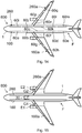
- the aircraft 1 shown in the figure 1 comprises a fuselage F and a set of electric generators comprising a first generator G1 associated with an engine E1 of the aircraft and a second generator G2 associated with an engine E2 of the aircraft.
- the aircraft 1 also comprises an electrical power distribution network 200.
- the electrical power distribution network comprises a set of busbars, among which a first busbar 120, 120a and a second busbar 220, 220a.
- Each of the two busbars comprises at least one part 120, respectively 220, extending in a longitudinal direction of the fuselage F.
- the first busbar comprises a part 120a in a left wing of the aircraft and the second busbar comprises a part 220a in a right wing of the aircraft. Similar conductors of part 120a and part 120 are electrically connected to each other. Likewise, similar conductors of part 220a and part 220 are electrically connected to each other.
- the electrical power distribution network 200 also includes a switching system 30.
- This switching system is electrically connected to the first electrical generator G1 and to the second electrical generator G2, as well as to the first busbar 120, 120a and to the second set bars 220, 220a.
- the switching system 30 includes a so-called normal operating mode, in which it is configured to connect electrically the first electric generator G1 at the first busbar 120, 120a and the second electric generator G2 at the second busbar 220, 220a.
- the first electric generator G1 is electrically connected to the switching system 30 via dedicated conductors (or bars) of the first busbar 120, 120a and the second electric generator G2 is electrically connected to the switching system via dedicated conductors of the second busbar 220, 220a.
- the first generator G1 located in the left wing of the aircraft, near the engine E1 is connected to dedicated conductors of part 120a of the first busbar, by a local electrical supply link between this generator and this part 120a of the first busbar.
- the second generator G2 located in the right wing of the aircraft, near the engine E2 is connected to dedicated conductors of part 220a of the second busbar, by a local electrical supply link between this generator and this part 220a of the second busbar.
- the aircraft 1 also comprises a set of electrical equipment distributed in the fuselage and each busbar of the busbar assembly comprises connection points at different locations distributed along its length.
- the aircraft 1 comprises a set of electrical equipment 40a ... 40j in the part of the fuselage shown in the figure 5 .
- These electrical equipments each require a power supply to operate.
- the first busbar 120 has connection points 24a ... 24h at different locations distributed along its length, in its part shown in the figure.
- the second busbar 220 has connection points 24i ... 24p at different locations distributed along its length, in its part shown in the figure.
- Each of the electrical items of the set of electrical items is connected to a connection point of a busbar of the set of busbars, via a local electrical supply link 42.
- the electrical equipment 40a is connected to connection point 24a of the first busbar 120.
- the equipment 40b, 40c and 40d are connected to the connection point 24d.
- the electrical equipment 40e and 40f are connected to the connection point 24g.
- the electrical equipment 40g is connected to the connection point 24i of the second busbar 220.
- the electrical equipment 40h and 40i are connected to the connection point 24l.
- the electrical equipment 40j is connected to the connection point 24o.
- the connection points 24a, 24d, 24g, 24i, 24l and 24o receiving local electrical supply connections 42 of electrical equipment are equipped with junction boxes provided with sockets or connectors allowing these connections to be easily connected local electrical supply 42.
- connection points not receiving a local electrical supply link are not equipped with such junction boxes in order to limit the weight of the aircraft.
- two consecutive connection points of a busbar are spaced a distance of approximately 50 to 70 cm. This distance corresponds for example to the distance between two structural frames of the aircraft.
- the junction boxes can for example be installed every 4 or 5 connection points in a major part of the fuselage. However, in areas of the fuselage corresponding to a particularly high density of electrical equipment, all the connection points, or sometimes one connection point in two, can be fitted with junction boxes.
- the set of busbars forms an infrastructure of the electrical power distribution network 200 of the aircraft.
- the various electrical equipment 40a ... 40i are each connected to a connection point of a busbar by a local electrical supply link 42. It is thus possible to easily add new electrical equipment to the fuselage, without modify this infrastructure: it suffices to set up a local electrical supply link between this new equipment and a busbar connection point. Preferably, this connection point is chosen as close as possible, on the busbar considered, to the new electrical equipment.
- This addition of new electrical equipment can be provided both during the manufacture of the aircraft and when the configuration of the aircraft is changed after it has been delivered to an airline.
- the aircraft 1 also comprises a third generator G3 near the engine E1 and a fourth generator G4 near the engine E2.
- the busbar assembly further includes a third busbar 320, 320a and a fourth busbar 420, 420a.
- the third busbar and the fourth busbar each have a part 320, respectively 420, extending in a longitudinal direction of the fuselage F.
- the four busbars follow segregated paths in the fuselage, as shown in the figure 3 . As indicated above, the part 120 of the first busbar travels in a left part of the fuselage and the part 220 of the second busbar travels in a right part of the fuselage.
- the part 320 of the third busbar travels in a left part of the fuselage and the part 420 of the fourth busbar travels in a right part of the fuselage.
- Part 120 of the first busbar and part 220 of the second busbar run through an upper part of the fuselage, while part 320 of the third busbar and part 420 of the fourth busbar run through a lower part of the fuselage fuselage.
- the third busbar comprises a part 320a in the left wing of the aircraft and the fourth busbar comprises a part 420a in the right wing of the aircraft.
- the third busbar 320, 320a and the fourth busbar 420, 420a are also connected to switching system 30.
- the switching system 30 is configured to electrically connect the third electric generator G3 to the third busbar and the fourth electric generator G4 to the fourth busbar.
- the third electric generator G3 is electrically connected to the switching system 30 via dedicated conductors (or bars) of the third busbar 320, 320a and the fourth electric generator G4 is electrically connected to the switching system via dedicated conductors of the fourth busbar 420, 420a.
- the third generator G3 located in the left wing of the aircraft, close to the engine E1 is connected to dedicated conductors of part 320a of the third busbar, by a local electrical supply link between this generator and this part 320a of the third busbar.
- the fourth generator G4 located in the right wing of the aircraft, near the engine E2 is connected to dedicated conductors of part 420a of the fourth busbar, by a local electrical supply link between this generator and this part 420a of the fourth busbar.
- a busbar 20 of the busbar assembly comprises a set of electrical conductors corresponding to bars 25a, 25b, 25c. Although three bars 25a, 25b and 25c are shown in the figure, this number of bars should not be interpreted as limiting the invention. Those skilled in the art will be able to adapt the number of bars as a function of the different electrical voltages to be distributed to the electrical equipment of the aircraft by means of the electrical power distribution network 200 and as a function of the number of distinct segregations required. These bars run in parallel or substantially parallel along a length of the busbar 20. They are separated from each other by an electrically insulating material 22, for example a plastic material or air. The set of bars is surrounded by an envelope 28.
- this envelope is formed from an electrically insulating material.
- the casing 28 is formed from an electrically conductive material.
- An electrically insulating material 22 is then placed between the bars 25a, 25b and 25c on the one hand and the casing 28 on the other hand.
- This other embodiment is advantageous because it allows the casing 28 to be used as an electrical current return conductor (for example example neutral conductor in alternating current, 0 volts in direct voltage, etc.) and / or as electromagnetic shielding making it possible to avoid electromagnetic disturbances of electrical equipment of the aircraft by electric currents flowing in the bars 25a, 25b, 25c.
- the busbar part 20 shown in the figure has a connection point 24.
- connection point has an opening 29 in the casing 28, for example on an upper face (in the figure) of said casing.
- the opening 29 thus delimits two parts 28a and 28b of the upper face of the envelope 28.
- the part of the set of bars 25a, 25b, 25c situated opposite the opening 29 is devoid of insulation 28 when this insulator corresponds to a plastic material, so as to allow the connection of a connection means on the bars 25a, 25b, 25c through the opening 29.
- a connection means corresponds for example to a connector comprising sets of blades forming a spring, capable of being placed on the bars.
- the switching system 30 includes a so-called reconfigured operating mode, capable of being activated in the event of a failure in the electrical power distribution network.
- the switching system 30 is configured to establish electrical connections between on the one hand the electric generators G1, G2 (and possibly G3, G4 according to the embodiment) of the set of electrical generators and on the other hand the busbars of the set of busbars, these electrical connections being modified with respect to electrical connections established in the normal operating mode.
- the switching system 30 is configured to establish electrical connections between busbars of the busbar assembly. This second variant can be combined with the first variant.
- the switching system modifies the electrical connections so as to supply the first busbar 120, 120a, thus as the third busbar 320, 320a, from the generator G1.
- the switching system comprises a main switching device and at least one switching device secondary switching remote from the main switching device.
- the main switching device is similar to the switching system 30 shown in the figures 1, 2 and 3 and described previously. For example, it performs an electrical heart function of the aircraft.
- the at least one secondary switching device is controlled by the switching system 30 to which it is connected by a specific communication link or by a communication network of the aircraft.
- a secondary switching device 32a is offset at one end of the busbars of the busbar assembly, for example in a rear part or in a front part of the fuselage F of the aircraft.
- the secondary switching device 32a comprises four switches K1, K2, K3, K4, corresponding for example to contactors which can be controlled by the switching system 30.
- these contactors include at least as many contacts as the busbars include electrical conductors 25a, 25b, 25c, etc.
- the contacts of switches K1, K2, K3 and K4 are open, so that they do not establish any connection between the busbars 120, 220, 320 and 420.
- the figure 6b illustrates a situation in which a failure X has occurred on the first busbar 120. This failure has the effect of electrically isolating between them two parts 120x and 120y of the first busbar 120.
- the switching system controls the remote switching 32a, so as to close the contacts of switch K1. This has the effect of connecting similar conductors to one another on the one hand from the part 120y of the first busbar and on the other hand from the third busbar 320. This part 120y of the first busbar is then supplied by the third generator G3 via the switching system 30.
- At least one of the busbars of the busbar assembly comprises at least two sections arranged end to end and electrically connected to each other. That is particularly advantageous when the aircraft 1 is formed by assembling sections of the fuselage F. These fuselage sections are then pre-equipped with busbar sections which are connected together during or after the assembly of the fuselage sections.
- each of the parts 120, 220, 320 and 420 of the first, second, third and fourth busbars is composed of an assembly of sections of busbars arranged end to end and electrically connected together.
- the busbar sections are specific to the fuselage sections in which they are integrated.
- each section of busbars integrated into a fuselage section consists of an assembly of modular sections of busbars arranged end to end and electrically connected to each other.
- these modular sections of busbars correspond to a limited number of lengths judiciously chosen so as to allow the pre-equipment of the various fuselage sections by combination of modular sections corresponding to these predefined lengths.
- a secondary switching device 32b is electrically connected to two consecutive sections (or two modular sections) of a busbar.
- a secondary switching device 32b is put in place between on the one hand two busbar sections 120j and 220j and on the other hand two busbar sections 120k and 220k.
- the sections 120j and 120k correspond to two consecutive sections of the first busbar 120.
- the sections 220j and 220k correspond to two consecutive sections of the second busbar 220.
- the secondary switching device 32b comprises four switches K11, K12, K13, K14 , corresponding for example to contactors that can be controlled by the switching system 30.
- these contactors include at least as many contacts as the busbars include electrical conductors 25a, 25b, 25c, etc.
- the contacts of the switches K11 and K12 are closed so as to establish electrical connections between similar electrical conductors of the sections 120j and 120k of the first busbar on the one hand and 220j and 220k of the second busbar on the other hand.
- the contacts of switches K13 and K14 are open, in such a way that they do not establish any connection between the first busbar and the second busbar.
- the figure 7b illustrates a situation in which a fault X has occurred on the section 120j first busbar 120.
- the switching system 30, although not shown in the figure, is considered to be to the left of the sections 120j and 220j in the figure.
- the failure X has the effect of interrupting the electrical supply to the busbar 120k by the generator G1 via the switching system 30 and the busbar 120j.
- the switching system 30 controls the opening of the contacts of switch K11 and the closing of the contacts of switch K14. This has the effect of connecting together the similar contacts of the section 220j of the second busbar and of the section 120k of the first busbar. This section 120k of the first busbar is then supplied by the second generator G2 via the switching system 30 and the busbar 220j.
- the busbar section 20t and the data link assembly 50t are mounted integral with one another.
- the busbar section 20t and the data link assembly 50t are fixed on a common support 62.
- the data links of the data link assembly 50t are attached to the 20t busbar section.
- these data links correspond to sheets of optical fibers
- these sheets of optical fibers are for example glued to one face of the busbar section 20t.
- the data links of the set of data links 50t correspond to twisted pairs of copper or aluminum wires.
- the data links correspond to optical fibers. In addition to a significant gain in mass, these optical fibers have the advantage of being insensitive to possible electromagnetic disturbances which could be produced when an electric current flows in bars of the section of busbar 20t.
- the busbar section 20t has connection points 24 at different locations distributed along its length.
- the set of data links 50t comprises connection points 54 at different locations distributed along its length and each arranged near (or facing) a connection point 24 of the busbar section 20t.
- the modular element 60 thus comprises pairs of connection points, each comprising on the one hand a connection point 24 of the busbar section 20t and on the other hand the connection point 54 of the set of data links 50t, located near said connection point 24.
- the busbar section 20t has a first interconnection point 27a and the data link assembly 50t has a first interconnection point 57a. These first interconnection points 27a and 57a are located at a first longitudinal end Ext1 of the modular element 60.
- first interconnection points 27a and 57a are provided for connecting the busbar section 20t and the assembly of connections 50t of data respectively to a busbar section and to a set of data links of a first other modular element arranged longitudinally in series with the modular element 60.
- the busbar section 20t has a second point of interconnection 27b and the data link assembly 50t includes a second interconnection point 57b.
- These second interconnection points 27b and 57b are located at a second longitudinal end Ext2 of the modular element 60.
- These second interconnection points 27b and 57b are provided for connecting the busbar section 20t and the assembly of connections 50t of data respectively to a busbar section and to a set of data links of a second other modular element arranged longitudinally in series with the modular element 60.
- the set of data links 50t also includes at least one connection point, said patch point, designed to receive a patch bay.
- this at least one mixing point is located at a longitudinal end of the modular element 60.
- the data link assembly 50t comprises two patch points 55a and 55b located respectively at the first longitudinal end Ext1 and at the second longitudinal end Ext2 of the modular element 60.
- the at least one patch point 55 is located between two connection points 54 of the set of data links 50t.
- the set of data links 50t also includes at least one data link between on the one hand each of the connection points distributed along its length and on the other hand the patch point. These data links 56 are not shown on the Figures 8 and 9 for reasons of clarity of said figures. As shown in the figure 10 schematically illustrating the data links corresponding to the figure 8 , at least one data link is provided between on the one hand each patch point 55a, 55b and on the other hand each connection point 54a, 54b ... 54f.
- the set of data links 50t comprises at least one data link 56b1 between the patch point 55a and the connection point 54b and at least one data link 56b2 between the patch point 55b and the connection point 54b.
- each link shown in the figure may in fact correspond to a set of optical fibers, for example 8 optical fibers.
- the set of data links 50t also includes data links 58 between the first interconnection point 57a and the second interconnection point 57b. These connections 58 are particularly useful for establishing communications through several modular elements 60.
- At least one data link 56a, 56b, ... 56f is provided between the patch point 55 and each connection point 54a, 54b ... 54f.
- at least one data link 58b is provided between the patch point 55 and each interconnection point 57a, 57b.
- the patch point (s) is (are) designed to receive a patch bay.
- the modular element 60 comprises for example at least one fixing provided to allow the fixing of the patch bay on the modular element.
- This attachment may in particular correspond to a nut or a screw, to a mechanical part designed to cooperate with a part of the patch bay so as to clip it onto the modular element, etc.
- the data links 56 arrive on one or more patch connectors which can be integrated in the corresponding patch bay.
- FIG 12 An example of interconnection of two consecutive modular elements is illustrated by the figure 12 , in the case of modular elements 60i, 60i + 1 similar to the modular element 60 shown in the figure 8 .
- the first end Ext1 of the modular element 60i + 1 is connected to the second end Ext2 of the modular element 60i.
- these two ends are arranged end to end, close to each other, so that the first interconnection point 27a of the busbar 20t of the modular element 60i + 1 faces the second interconnection point 27b of the busbar 20t of the modular element 60i and the first interconnection point 57a of the data link assembly 50t of the modular element 60i + 1 faces the second interconnection point 57b of the set of data links 50t of the modular element 60i.
- the similar conductors of the interconnection points 27a and 27b are electrically connected to each other by means of electrical connections 66.
- the interconnection points 27a and 27b correspond to terminal blocks and the electrical connections 66 then correspond to cables of appropriate section.
- the interconnection points 27a and 27b correspond to connectors.
- the electrical connections 66 then correspond for example to a connection of said connectors. In particular, when they are connected, these connectors can slide longitudinally relative to one another so as to absorb longitudinal displacements of the two modular elements relative to each other, in particular during deformations structural of the aircraft in which the modular elements are installed.
- a patch bay 64 is installed so as to receive the interconnection points 57a of the modular element 60i + 1 and 57b of the modular element 60i, as well as the patch points 55a of the modular element 60i + 1 and 55b of the modular element 60i.
- these interconnection and patching points are equipped with connectors which are then integrated in the patching bay.
- the patch bay allows the required interconnections to be implemented, for example by means of jumpers. It also allows the integration of active elements, for example of the switch type or of the router type, when such equipment is necessary for making the interconnections. These active elements correspond, for example, to switches or routers of the Ethernet type or of the USB type.
- the jumpers correspond to wired jumpers when the data links are of the wired type (for example twisted pairs of copper or aluminum wires) or to optical jumpers when the data links correspond to optical fibers.
- the patch bay receiving the interconnection points 57a, 57b and the patch points 55a, 55b, allows the installation of jumpers to make different types of interconnections.
- a first type of interconnection corresponds to an interconnection of a first link between one of the patch points 55a, 55b and a connection point 24 of the data link assembly of one of the modular elements 60i, 60i + 1, with a second link between one of the patch points 55a, 55b and a connection point 24 of the data link assembly of one of the modular elements 60i, 60i + 1.
- a second type of interconnection corresponds to an interconnection of a first link between one of the patch points 55a, 55b and a connection point 24 of the data link assembly of one of the modular elements 60i, 60i + 1, with a second link arriving at one of the interconnection points 57a, 57b.
- a third type of interconnection corresponds to an interconnection of a first link arriving on one of the interconnection points 57a, 57b, with a second link arriving on the other of the interconnection points 57a, 57b.
- the patch bay is fixed to at least one of the modular elements 60i, 60i + 1 so as to cover the patch points 55a, 55b and the interconnection points 57a, 57b, which enter the brewing bay by one or more cutouts thereof.
- the patch bay is fixed either on at least one of the modular elements 60i, 60i + 1, near its end Ext2, Ext1, or on the structure of the aircraft near the ends Ext2, Ext1 of the modular elements 60i, 60i + 1, without the patching bay covering these interconnection and patching points.
- the interconnection points 57a, 57b and the patch points 55a, 55b are then arranged at the ends of the data links of the sets of data links 50t sufficiently long and flexible enough to allow the integration of said interconnection points and patching in patch bay 64.
- each of the different pairs of connection points 24, 54 of the modular element 60 is designed to receive a mixed junction box for electrical power distribution and data communication 68.
- a mixed junction box allows the connection of one or more local power distribution and / or data distribution links to one or more electrical equipment of the aircraft.
- the use of mixed junction boxes facilitates the connection of electrical equipment to modular elements 60: thus, it is not necessary to connect each electrical equipment to the 20t busbar section and to a data link of the set of 50t data links.
- the junction box 68 is for example provided with connectors facilitating the connection of local connections to the electrical equipment.
- a pair of connection points is only fitted with a junction box if electrical equipment is connected to this pair of connection points. This avoids an unnecessary increase in the mass of the aircraft.
- the busbar section 20t comprises at least one flexible part designed to allow deformations of the modular element 60 in response to deformations of the fuselage F of an aircraft when the modular element is installed in said fuselage of an aircraft.
- each electrically conductive element of the busbar section 20t comprises a spring over part of its length.
- the length L of a modular element 60 is between 3 and 10 meters, preferably between 6 and 10 meters.
- two consecutive pairs of connection points of the modular element are spaced by a distance of about 50 to 70 cm. This distance corresponds for example to the distance between two structural frames of the aircraft.
- the junction boxes 68 can for example be installed every 4 or 5 pairs of connection points in a major part of the fuselage. However, in areas of the fuselage corresponding to a particularly high density of electrical equipment, all the pairs of connection points, or sometimes a couple of connection points on two, can be fitted with junction boxes.
- the invention also relates to an aircraft 1 comprising a fuselage F and a set of electrical equipment distributed in the fuselage.
- the aircraft comprises a mixed electrical power distribution and data communication network 600 comprising a set of modular elements 60a ... 60q similar to the above-mentioned modular element 60.
- the mixed network 600 includes a first mixed electrical power distribution and data communication sub-network 160, 160a.
- This first mixed sub-network is formed by assembling between them modular elements 60a ... 60h forming a first subset of the set of modular elements.
- the first mixed sub-network comprises a part 160 which extends longitudinally in the fuselage F of the aircraft.
- it also comprises a part 160a which extends in the left wing of the aircraft.
- the mixed network 600 also includes a second mixed electrical power distribution and data communication sub-network 260, 260a.
- This second mixed sub-network is formed by assembling between them modular elements 60i ... 60q forming a second sub-assembly of the assembly modular elements.
- the second mixed sub-network includes a part 260 which extends longitudinally in the fuselage F of the aircraft.
- it also comprises a part 260a which extends in the right wing of the aircraft.
- the first sub-network 160, 160a and the second sub-network 260, 260a take segregated paths in the fuselage F, for example in a left part of the fuselage for the first sub-network and in a right part of the fuselage for the second sub network, as shown in the figure 14 .
- Two consecutive modular elements are for example assembled together as described with reference to the figure 12 .
- Each electrical item of the set of electrical items of equipment is connected to a connection point 24 of the busbar section 20t of a modular element 60a ... 60q via a local electrical supply link and / or to a point connection 54 of the set of data links 50t of said modular element by a local data link.
- electrical equipment and local connections are not shown.
- modular elements in accordance with the invention to build the mixed network 600 makes it possible to easily adapt this network to any type of aircraft, without requiring busbars or specific data link sets. to the aircraft in question, in particular with regard to their length.
- the use of one or a few types of modular elements of predetermined lengths makes it possible to adapt such a network to any type of aircraft.
- the aircraft 1 shown in the figure 15 comprises a fuselage F and a set of electric generators comprising a first generator G1 associated with an engine E1 of the aircraft and a second generator G2 associated with an engine E2 of the aircraft.
- the aircraft 1 also comprises a mixed electrical power distribution and data communication network 600.
- the mixed network 600 comprises a set of busbars, including a first busbar and a second busbar.
- a set of data links is associated with each busbar in the busbar set.
- Each set of data links extends substantially parallel to the busbar with which it is associated.
- the first busbar and the set of data links associated with this first busbar form a first mixed electrical power distribution and data communication sub-network 160, 160a.
- the second busbar and the set of data links associated with this second busbar form a second mixed electrical power distribution and data communication subnetwork 260, 260a.
- Each of the two subnetworks comprises at least one part 160, respectively 260, extending in a longitudinal direction of the fuselage F.
- These two subnetworks take segregated paths in the fuselage F of the aircraft, respectively in a left part of the fuselage (or port side) for part 160 of the first sub-network and in a right part of the fuselage (or starboard) for part 260 of the second sub-network. This avoids a common failure on the two subnets in the event of an incident in one part of the fuselage.
- the first subnetwork comprises a part 160a in a left wing of the aircraft and the second subnetwork comprises a part 260a in a right wing of the aircraft.
- the electrical power distribution network also includes a switching system 30.
- This switching system is electrically connected to the first electrical generator G1 and to the second electrical generator G2, as well as to the first busbar of the first sub- network 160, 160a and to the second busbar of the second sub-network 260, 260a.
- the switching system 30 includes a so-called normal operating mode, in which it is configured to electrically connect the first electrical generator G1 to the first busbar and the second electrical generator G2 to the second busbar.
- the aircraft 1 also includes a set of electrical equipment distributed in the fuselage. For reasons of clarity of the figure, this electrical equipment is not shown on the figure 15 .
- each busbar 20 of the set of busbars comprises connection points 24 at different locations distributed along its length and each set of data links 50 comprises connection points 54 at different locations distributed along its length.
- the connection points 54 are each arranged near (or facing) a connection point 24 of the busbar 20 with which the data link assembly 50 is associated, so as to form pairs of connection points comprising each a connection point 24 of the busbar and a connection point 54 of the associated data link assembly.
- two consecutive pairs of connection points are spaced a distance of about 50 to 70 cm. This distance corresponds for example to the distance between two structural frames of the aircraft.
- the mixed electrical power distribution and data communication network 600 has been described in the particular case where it comprises 2 subnetworks 160, 160a and 260, 260a, the third aspect of the invention is in no way limited to this number of subnets.
- the mixed network 600 can comprise 4 subnetworks using segregated paths in the fuselage of the aircraft, in the same way as the electrical power distribution network 200 in accordance with the first aspect of the invention can comprise 4 sets of bars taking segregated paths in the fuselage.
- At least one busbar 20 of the busbar assembly comprises at least two modular sections arranged end to end and electrically connected to each other.
- This at least one busbar is part of one of the subnetworks 160, 160a or 260, 260a.
- Each of said at least two modular sections of the at least one busbar forms part of a modular element also comprising a set of data links extending substantially parallel to the modular section considered.
- Such a modular element corresponds, for example, to the modular element 60 according to an embodiment of the second aspect of the invention.
- the sets of data links of consecutive modular elements are linked together so as to form the set of data links 50 associated with the busbar 20 considered.
- the mixed electrical power distribution and data communication network 600 comprises a set of junction boxes, each junction box 70 being connected to a pair of connection points 24, 54 as shown in the figure 17 .
- These junction boxes are provided to allow the electrical equipment of the aircraft to be connected to the connection points 24 of the busbar 20 and to the connection points 54 of the set of data links 50.
- the number junction boxes 70 installed on the power distribution sub-networks distribution and data distribution is a function of the density of the electrical equipment in the fuselage F of the aircraft.
- the junction boxes can be installed every 4 or 5 pairs of connection points 24, 54, as shown in the lower part of the figure 17 .
- the junction boxes can be installed every 2 pairs of connection points, or even on each couple of connection points, as shown in the upper part of the figure 17 .
- the set of data links 50 comprises at least one particular connection point, called patch point 55.
- This at least one patch point 55 is provided for receiving a patch bay 64.
- the set of data links 50 includes data links between the patch point 55 and various connection points 54.
- the patch bay makes it possible to connect said data links to one another by means of jumpers.
- Each of the electrical items of the set of electrical items of equipment is connected to a pair of connection points via a local electrical supply link 42 and / or via a local data link 43, as shown in the figure 20 .
- the aircraft 1 comprises a set of electrical equipment 40a ... 40j in the part of the fuselage F shown in the figure. This electrical equipment each requires an electrical supply to operate, except the 40g equipment which is energy independent. Electrical equipment, except 40d equipment, also each requires a data link.
- Each electrical equipment is connected to a single pair of connection points, by means of said local connections 42 and / or 43, preferably via a junction box 70a ... 70f.
- the part 160 of the first sub-network is equipped with 3 junction boxes 70a, 70b, 70c and the part 260 of the second sub-network is equipped with 3 junction boxes 70d, 70e, 70f.
- the electrical equipment 40a is connected to the junction box 70a by a local power supply link 42 and by a local data link 43.
- the electrical equipment 40b and 40c are connected to the junction box 70b by a connection local power supply 42 and by a local data link 43.
- the equipment 40d is connected to the junction box 70b only by a local power supply link 42.
- the electrical equipment 40e and 40f are connected to the junction box 70c by a local power supply link 42 and by a data link local 43.
- the electrical equipment 40g is connected to the junction box 70d only by a local data link 43.
- the electrical equipment 40h and 40i are connected to the junction box 70e by a local electrical supply link 42 and by a local data link 43.
- the electrical equipment 40j is connected to the junction box 70f by a local power supply link 42 and by a local data link 43.
- the junction boxes 70a , 70b, 70c on the one hand and 70d, 70e, 70f on the other hand are installed every 4 or 5 pairs of connection points, respectively on part 160 of the first subnetwork and on the part 260 of the second subnet. When the pairs of connection points are spaced 50 cm apart, for example, two consecutive junction boxes are then spaced about 2 meters apart.
- a junction box 70 comprises a power supply connector 724, a data link connector 754 and a set of locations E1, E2, ... E6 designed to each receive an interface module.
- the power supply connector 724 is provided to cooperate with the connection point 24 of the pair of connection points to which the junction box is connected.
- the data link connector 754 is designed to cooperate with the connection point 54 of the set of data links belonging to the pair of connection points to which the junction box is connected.
- This data link connector corresponds for example to at least one multi-fiber optic connector when the data links of the distribution network 600 correspond to optical fibers.
- the junction box 70 also includes a set of electrical connections 72 extending between the power supply connector 724 and the various locations E1, E2, ... E6 provided for receiving the interface modules, as well as a set of data links 75 extending between the data link connector 754 and the various locations provided for receiving the interface modules.
- the data links of the distribution network 600 correspond to optical fibers and the junction box 70 further comprises a data link converter 78.
- This converter is provided for converting communications by optical fibers into wired communications and vice versa.
- the data link assembly 75 then includes fiber optic data links 75a between the data link connector 754 and the data link converter 78, as well as data links 75b using electrical signals between the data converter data links 78 and the various locations E1, E2, ... E6 provided for receiving the interface modules.
- This variant has the advantage of allowing communications by optical fibers over the set of data links of the mixed network 600 of electrical power distribution and data communication. These communications are thus insensitive to electromagnetic disturbances.
- junction box 70 which allows a wired connection of the data links 75b with the interface modules capable of being installed in the locations E1, E2, ... E6 .
- a wired connection has better reliability than an optical connection insofar as the interface modules are liable to be replaced or moved. Indeed, such a wired connection is less sensitive to dust and vibrations than an optical connection.
- the connectors 724 and 754 are arranged on a rear face of the junction box 70.
- the electrical connections 72 and the data links 75 are produced by means of a backplane board of the junction box . These connections arrive on connectors of the backplane card, arranged opposite the locations E1, E2, ... E6 so that the interface modules capable of being installed in said locations can be plugged into these connectors .
- electrical equipment 40k ... 40q are connected to electrical interface modules Pa, Pb by local electrical supply links 42k ... 42q and / or to interface interface modules of data Da, Db by local data links 43k ... 43q.
- the electrical interface modules Pa, Pb are respectively installed in the locations E2, E6 of the junction box 70 and the data link interface modules Da, Db are respectively installed in the locations E3, E5 of the junction box 70.
- electrical equipment which requires an electrical supply and a data link is connected to an electrical interface module by a local electrical supply link and to a data link interface module through a local data link.
- the electrical equipment 40k is connected to the electrical interface module Pa by a local power supply link 42k and to the data link interface module Da by a local data link 43k.
- the local electrical supply links 42k ... 42q and the local data links 43k ... 43q are terminated by connectors capable of cooperating with connectors of the interface modules.
- the rear face of the junction box 70 includes supports designed to hold in position the connectors of the local power supply links and of the local data links, so that these connectors are connected to the corresponding connectors of the interface modules when the interface modules are installed in their respective locations in the junction box. This advantageously makes it possible to remove and install the interface modules in the locations E1, E2, ... E6 of the junction box without having to manipulate the connectors of the various data links. This also makes it possible to avoid connection errors of said links.
- the junction box includes a backplane 73 card.
- Connectors 724 and 754 are integral with the backplane card. These connectors are arranged in such a way that when the junction box is installed on a couple of connection points, as shown in the figure, the power supply connector 724 is connected to the connection point of the busbar 20 and the connector of data links 754 can receive a connector of a 54x end of data links of the connection point of the set of data links 50.
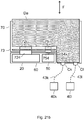
- the interface module Da is shown inserted in a location of the junction box 70. This interface module is connected to the backplane board 73 by means of a power supply connector 72i is a data link connector 75i.
- the arrow F represents a direction of extraction (upwards in the figure) and insertion (downwards in the figure) of the interface module in the junction box 70.
- the local data links 43k and 43l to the electrical equipment 40k and 40l are terminated by respective connectors Ck and Cl connected to the interface module.
- the rear face of the junction box 70 (shown at the bottom in the figure) includes supports, not shown, intended to hold the connectors Ck and Cl in position.
- the junction box 70 may include a mixed interface module providing an electrical interface module function, as mentioned above, and a data link interface module function, as mentioned above.
- this mixed interface module can respond to space constraints of the locations of the junction box 70.
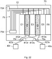
- electrical equipment 40r, 40s are each connected to a respective connector 79r, 79s of the junction box 70, by respective local links 423r, 423s. These local links are of the mixed power supply and data link type.
- the connector 79r and the connector 79s of the junction box are each connected to an electrical interface module P and to a data link interface module D, by internal links to the junction box.
- the connector 79r is connected to the electrical interface module P by an electrical link 412r and to the data link interface module D by a data link 413r.
- the connector 79s is connected to the electrical interface module P by an electrical link 412s and to the data link interface module D by a data link 413s.
- the pinout of the various connectors 79r, 79s of the junction box is similar for all of said connectors.
- This allows identical mixed local links to be used between the various electrical equipment and the connectors of the junction boxes to which these electrical equipment are connected. This results in a simplification of the connections of the electrical equipment by means of said mixed local links.
- this second particular embodiment is described with two electrical equipment and two interface modules, it is in no way limited to these numbers of electrical equipment and interface modules.
- the internal connections 412r, 412s, 413r, 413s are terminated by connectors capable of cooperating with connectors of the interface modules P and D.
- the rear face of the junction box 70 includes supports designed to hold the connectors of said internal links in position, so that these connectors are connected to the corresponding connectors of the interface modules when the interface modules are installed in their respective locations from the junction box. This advantageously makes it possible to remove and install the interface modules in the locations E1, E2, ... E6 of the junction box without having to manipulate the connectors of the various internal links. This also makes it possible to avoid connection errors of said links.
- modular elements 60i, 60i + 1 for an electrical power distribution network of an aircraft each comprise a casing 28.
- Each modular element comprises a section of a busbar whose electrical conductors, not shown in the figure , are housed in the casing 28.
- the busbar section extends along the length of the modular element considered.
- the busbar section of a modular element 60i, 60i + 1 has a first interconnection point 27a at a first longitudinal end and a second interconnection point 27b at a second longitudinal end.
- the first and second interconnection points 27a and 27b are provided for connecting the busbar section to a busbar section of another modular element arranged longitudinally in series with the modular element considered.
- the second interconnection point 27b of the modular element 60i is connected to the first interconnection point 27a of the modular element 60i + 1.
- the connection between the busbars of two consecutive modular elements corresponds to a connection making it possible to absorb longitudinal deformations of the aircraft.
- This connection is by example produced by means of a connector provided to allow sliding of conductive elements participating in said connection.
- the envelope 28 corresponds to a structural part of the aircraft, in this case a part intended to support luggage compartments 96 in the cabin of the aircraft. This part is for example a metal part or a part made of composite material whose thickness is chosen to support the mass of the luggage compartments.
- the envelope 28 corresponding to each modular element 60i, 60i + 1 is fixed, by fixing means not shown in the figure, to a set of structural frames 94 of the aircraft.
- the envelopes 28 of the various modular elements support the luggage compartments 96 thanks to fixings 95.
- these fixings 95 can be slidably mounted on the envelopes 28 of the modular elements so as to allow the luggage compartments to slide according to the length of the aircraft fuselage. In the example shown in the figure, the length of the envelope 28 corresponding to each modular element extends along two inter-frames of the fuselage of the aircraft.
- the term intercadre here designates the space between two consecutive structural frames of the fuselage.
- the length of the envelope 28 could also extend according to a single frame or according to a higher number of frames.
- the busbar section of a modular element has connection points 24 at different locations distributed along its length.
- An opening of the casing 28 is provided opposite each connection point 24 so as to allow the connection of at least one electrical equipment item of the aircraft to the busbar section by means of a local electrical connection.
- the connection points are distributed over the busbar section corresponding to each modular element so as to have a connection point 24 for each frame of the fuselage of the aircraft.
- Other arrangements are possible without departing from the scope of the invention, for example a connection point for two inter-frames of the fuselage.
- each modular element 60i, 60i + 1 form part of an electrical power distribution network of the aircraft, for example a network of distribution of electrical power similar to the 200 or 600 networks already described with reference to the first and second aspects of the invention.
- each modular element also comprises a set of data links, similarly to the modular elements described with reference to the second aspect of the invention. Consequently, this advantageous embodiment is not described further, all the embodiments described with reference to the second aspect of the invention also being applicable.
- the casing 28 of a section of busbars of a modular element forms part of a section of floor rail 98 of an aircraft.
- the floor rail may correspond to a floor rail not provided for fixing seats or even to a seat rail provided for fixing seats in the passenger cabin of the aircraft.
- only part of the length of the floor rail section 98 is shown in the figure.
- each modular element is similar to the modular elements 60i, 60i + 1 described with reference to the figure 23 .
- these modular elements can be arranged in series and linked together by interconnection points 27a, 27b.
- three conductive elements 25a, 25b, 25c of the busbar section are housed in the casing 28. This example is not, however, limitative of the number of conductors that the play may include. bars.
- the conductive elements are arranged horizontally inside the casing 28, so as to allow connection points 24 to be produced on a lateral face of the section of floor rail 98.
- the term horizontal here means that the conductive elements are arranged horizontally when the section of floor rail is installed on a floor of the aircraft fuselage cabin, the aircraft being parked on the ground.
- An opening 29 of the casing 28 is provided opposite each connection point 24 so as to allow the connection of at least one electrical equipment of the aircraft to the busbar section by means of a local electrical connection.
- the floor rail is a seat rail
- the upper part of the seat rail has a groove 97 allowing the fixing of seats.
- the electrical power distribution network 200 of an aircraft according to the first aspect of the invention can be produced by assembling modular elements 60 according to the second aspect of the invention.
- the mixed electrical power distribution and data communication network 600 in accordance with the third aspect of the invention can be produced by assembling modular elements in accordance with the second aspect of the invention.
- the junction boxes 68 described in connection with the second aspect of the invention may be similar to the junction boxes 70 described in more detail in connection with the third aspect of the invention.
Landscapes
- Engineering & Computer Science (AREA)
- Computer Networks & Wireless Communication (AREA)
- Signal Processing (AREA)
- Aviation & Aerospace Engineering (AREA)
- Medical Informatics (AREA)
- General Health & Medical Sciences (AREA)
- Computing Systems (AREA)
- Health & Medical Sciences (AREA)
- Power Engineering (AREA)
- Connection Or Junction Boxes (AREA)
- Small-Scale Networks (AREA)
- Connector Housings Or Holding Contact Members (AREA)
- Supply And Distribution Of Alternating Current (AREA)
- Mechanical Engineering (AREA)
- Installation Of Indoor Wiring (AREA)
Claims (11)
- Luftfahrzeug (1), welches aufweist:- einen Rumpf (F);- eine Gesamtheit von Stromgeneratoren, die wenigstens einen ersten Stromgenerator (G1) und einen zweiten Stromgenerator (G2) umfasst;- eine Gesamtheit von elektrischen Einrichtungen (40a, ..., 40j), die im Rumpf verteilt sind; und- ein Stromverteilungsnetz (200), welches aufweist:dadurch gekennzeichnet, dass:- eine Gesamtheit von Sammelschienen, die wenigstens eine erste Sammelschiene (120, 120a) und eine zweite Sammelschiene (220, 220a) umfasst; und- ein Schaltsystem (30),- jede Sammelschiene der Gesamtheit von Sammelschienen sich wenigstens teilweise in einer Längsrichtung des Rumpfes (F) erstreckt;- die erste Sammelschiene (120, 120a) und die zweite Sammelschiene (220, 220a) auf abgetrennten Wegen im Rumpf verlaufen;- das Schaltsystem (30) mit dem ersten Stromgenerator (G1) und dem zweiten Stromgenerator (G2) sowie mit der ersten Sammelschiene (120, 120a) und der zweiten Sammelschiene (220, 220a) elektrisch verbunden ist;- das Schaltsystem (30) eine sogenannte normale Betriebsart aufweist, in welcher es dafür ausgelegt ist, den ersten Stromgenerator (G1) mit der ersten Sammelschiene (120, 120a) und den zweiten Stromgenerator (G2) mit der zweiten Sammelschiene (220, 220a) elektrisch zu verbinden;- jede Sammelschiene der Gesamtheit von Sammelschienen Verbindungspunkte (24) an verschiedenen Stellen aufweist, die über ihre Länge verteilt sind; und- jede der elektrischen Einrichtungen der Gesamtheit von elektrischen Einrichtungen (40a, ..., 40j) mit einem Verbindungspunkt nur einer Sammelschiene der Gesamtheit von Sammelschienen über eine Verbindung zur lokalen Stromversorgung (42) verbunden ist.
- Luftfahrzeug nach Anspruch 1, dadurch gekennzeichnet, dass sich die erste Sammelschiene auch zum Teil (120a) in einer ersten Tragfläche des Luftfahrzeugs erstreckt und sich die zweite Sammelschiene auch zum Teil (220a) in einer zweiten Tragfläche des Luftfahrzeugs erstreckt.
- Luftfahrzeug nach einem der Ansprüche 1 oder 2, dadurch gekennzeichnet, dass der erste Stromgenerator (G1) und der zweite Stromgenerator (G2) mit dem Schaltsystem (30) über Sammelschienen elektrisch verbunden sind.
- Luftfahrzeug nach Anspruch 3, dadurch gekennzeichnet, dass der erste Stromgenerator mit dem Schaltsystem über dedizierte Leiter der ersten Sammelschiene elektrisch verbunden ist und der zweite Stromgenerator mit dem Schaltsystem über dedizierte Leiter der zweiten Sammelschiene elektrisch verbunden ist.
- Luftfahrzeug nach einem der vorhergehenden Ansprüche, dadurch gekennzeichnet, dass das Stromverteilungsnetz (200) außerdem eine dritte Sammelschiene (320, 320a) und eine vierte Sammelschiene (420, 420a) aufweist, welche sich wenigstens teilweise in einer Längsrichtung des Rumpfes erstrecken, wobei die erste, zweite, dritte und vierte Sammelschiene auf abgetrennten Wegen im Rumpf des Luftfahrzeugs verlaufen.
- Luftfahrzeug nach Anspruch 5, dadurch gekennzeichnet, dass die Gesamtheit von Stromgeneratoren außerdem einen dritten Stromgenerator (G3) und einen vierten Stromgenerator (G4) umfasst und in der normalen Betriebsart das Schaltsystem dafür ausgelegt ist, den dritten Stromgenerator (G3) mit der dritten Sammelschiene (320, 320a) und den vierten Stromgenerator (G4) mit der vierten Sammelschiene (420, 420a) elektrisch zu verbinden.
- Luftfahrzeug nach einem der vorhergehenden Ansprüche, dadurch gekennzeichnet, dass das Schaltsystem (30) eine sogenannte rekonfigurierte Betriebsart aufweist, die im Falle des Auftretens einer Störung im Stromverteilungsnetz (200) aktivierbar ist und in welcher es dafür ausgelegt ist:- elektrische Verbindungen zwischen den Stromgeneratoren (G1, ..., G4) der Gesamtheit von Stromgeneratoren und den Sammelschienen der Gesamtheit von Sammelschienen herzustellen, wobei diese elektrischen Verbindungen in Bezug auf elektrische Verbindungen, die in der normalen Betriebsart hergestellt sind, verändert sind; und/oder- elektrische Verbindungen zwischen den Sammelschienen der Gesamtheit von Sammelschienen herzustellen.
- Luftfahrzeug nach einem der vorhergehenden Ansprüche, dadurch gekennzeichnet, dass das Schaltsystem (30) eine Hauptschaltvorrichtung und wenigstens eine sekundäre Schaltvorrichtung (32a, 32b), die von der Hauptschaltvorrichtung (30) entfernt angeordnet ist, umfasst.
- Luftfahrzeug nach den Ansprüchen 7 und 8, dadurch gekennzeichnet, dass in der rekonfigurierten Betriebsart des Schaltsystems die wenigstens eine sekundäre Schaltvorrichtung so gesteuert werden kann, dass eine oder mehrere elektrische Verbindungen zwischen Sammelschienen der Gesamtheit von Sammelschienen hergestellt werden.
- Luftfahrzeug nach einem der vorhergehenden Ansprüche, dadurch gekennzeichnet, dass wenigstens eine der Sammelschienen der Gesamtheit von Sammelschienen wenigstens zwei modulare Abschnitte umfasst, die Ende an Ende angeordnet und elektrisch miteinander verbunden sind.
- Luftfahrzeug nach Anspruch 10 und einem der Ansprüche 8 oder 9, dadurch gekennzeichnet, dass eine sekundäre Schaltvorrichtung mit zwei aufeinander folgenden modularen Abschnitten einer Sammelschiene elektrisch verbunden ist, um in der normalen Betriebsart elektrische Verbindungen zwischen ähnlichen elektrischen Leitern der zwei modularen Abschnitte herzustellen und in der rekonfigurierten Betriebsart elektrische Verbindungen zwischen einerseits elektrischen Leitern wenigstens eines der zwei modularen Abschnitte und andererseits elektrischen Leitern einer anderen Sammelschiene herzustellen.
Applications Claiming Priority (3)
| Application Number | Priority Date | Filing Date | Title |
|---|---|---|---|
| FR1757396A FR3069969B1 (fr) | 2017-08-02 | 2017-08-02 | Element modulaire pour un reseau mixte d'un aeronef |
| FR1760372A FR3073337B1 (fr) | 2017-11-06 | 2017-11-06 | Element modulaire pour un reseau de distribution de puissance electrique d'un aeronef |
| EP18182086.1A EP3439244B1 (de) | 2017-08-02 | 2018-07-06 | Modulares element für ein gemischtes luftfahrzeugnetzwerk |
Related Parent Applications (2)
| Application Number | Title | Priority Date | Filing Date |
|---|---|---|---|
| EP18182086.1A Division-Into EP3439244B1 (de) | 2017-08-02 | 2018-07-06 | Modulares element für ein gemischtes luftfahrzeugnetzwerk |
| EP18182086.1A Division EP3439244B1 (de) | 2017-08-02 | 2018-07-06 | Modulares element für ein gemischtes luftfahrzeugnetzwerk |
Publications (2)
| Publication Number | Publication Date |
|---|---|
| EP3565189A1 EP3565189A1 (de) | 2019-11-06 |
| EP3565189B1 true EP3565189B1 (de) | 2020-06-17 |
Family
ID=62784063
Family Applications (3)
| Application Number | Title | Priority Date | Filing Date |
|---|---|---|---|
| EP19176678.1A Active EP3565189B1 (de) | 2017-08-02 | 2018-07-06 | Flugzeug mit stromverteilungsnetz |
| EP18182086.1A Active EP3439244B1 (de) | 2017-08-02 | 2018-07-06 | Modulares element für ein gemischtes luftfahrzeugnetzwerk |
| EP19176686.4A Active EP3565190B1 (de) | 2017-08-02 | 2018-07-06 | Flugzeug mit einem hybriden stromverteilungs- und datenkommunikationsnetz |
Family Applications After (2)
| Application Number | Title | Priority Date | Filing Date |
|---|---|---|---|
| EP18182086.1A Active EP3439244B1 (de) | 2017-08-02 | 2018-07-06 | Modulares element für ein gemischtes luftfahrzeugnetzwerk |
| EP19176686.4A Active EP3565190B1 (de) | 2017-08-02 | 2018-07-06 | Flugzeug mit einem hybriden stromverteilungs- und datenkommunikationsnetz |
Country Status (3)
| Country | Link |
|---|---|
| US (1) | US10971948B2 (de) |
| EP (3) | EP3565189B1 (de) |
| CN (1) | CN109383830B (de) |
Cited By (1)
| Publication number | Priority date | Publication date | Assignee | Title |
|---|---|---|---|---|
| FR3122409A1 (fr) | 2021-04-28 | 2022-11-04 | Airbus Operations (S.A.S.) | Aéronef comportant un réseau de distribution de puissance électrique. |
Families Citing this family (2)
| Publication number | Priority date | Publication date | Assignee | Title |
|---|---|---|---|---|
| FR3095422B1 (fr) * | 2019-04-25 | 2022-01-21 | Safran Helicopter Engines | Réseau d’alimentation en énergie électrique pour aéronef |
| EP4148924B1 (de) | 2021-09-10 | 2026-02-11 | Airbus Operations GmbH | Stromschiene für ein flugzeug, verfahren zur herstellung einer solchen stromschiene und flugzeug mit einer solchen stromschiene |
Family Cites Families (11)
| Publication number | Priority date | Publication date | Assignee | Title |
|---|---|---|---|---|
| FR2733868B1 (fr) * | 1995-05-03 | 1997-07-04 | Alsacienne Et Lorraine De Tele | Dispositif modulaire adaptable d'interconnexion ou de mise en communication de differents appareils ou reseaux locaux informatiques et/ou de communication et un procede mettant en oeuvre ce dispositif |
| GB2443002A (en) * | 2006-10-16 | 2008-04-23 | Converteam Ltd | dc power distribution system |
| US8793026B2 (en) | 2010-09-15 | 2014-07-29 | The Boeing Company | Electrical load management system |
| EP2442425B1 (de) * | 2010-10-15 | 2016-03-30 | Airbus Defence and Space SA | Elektrisches Leistungssteuerungssystem für ein Fahrzeug |
| FR3010387B1 (fr) * | 2013-09-10 | 2015-10-09 | Airbus Operations Sas | Aeronef comprenant un dispositif de commande d'une tuyere a section variable alimente par deux alimentations electriques independantes |
| US9561761B2 (en) * | 2013-10-11 | 2017-02-07 | The Boeing Company | Modular equipment center zonal standalone power system control architecture |
| US9561867B2 (en) * | 2013-10-11 | 2017-02-07 | The Boeing Company | Modular equipment center lightning threat reduction architecture |
| EP2945244B1 (de) * | 2014-05-15 | 2022-07-06 | Airbus Operations GmbH | Leistungs- und Datenverteilungsmodul und Verfahren zur Leistungs- und Datenverteilung in einem Flugkörper |
| CA2996844A1 (en) * | 2014-08-29 | 2016-06-16 | Tzunum, Inc. | Power train for a hybrid-electric aircraft |
| US10065583B2 (en) * | 2015-10-08 | 2018-09-04 | Gulfstream Aerospace Corporation | Integrated power distribution, data network, and control architectures for a vehicle |
| CN106505744B (zh) * | 2016-11-08 | 2018-02-27 | 中国商用飞机有限责任公司北京民用飞机技术研究中心 | 消除主电能传输线束的飞机供电系统及其电能分配方法 |
-
2018
- 2018-07-06 EP EP19176678.1A patent/EP3565189B1/de active Active
- 2018-07-06 EP EP18182086.1A patent/EP3439244B1/de active Active
- 2018-07-06 EP EP19176686.4A patent/EP3565190B1/de active Active
- 2018-07-31 US US16/050,547 patent/US10971948B2/en active Active
- 2018-08-02 CN CN201810871815.5A patent/CN109383830B/zh active Active
Non-Patent Citations (1)
| Title |
|---|
| None * |
Cited By (2)
| Publication number | Priority date | Publication date | Assignee | Title |
|---|---|---|---|---|
| FR3122409A1 (fr) | 2021-04-28 | 2022-11-04 | Airbus Operations (S.A.S.) | Aéronef comportant un réseau de distribution de puissance électrique. |
| US12054280B2 (en) | 2021-04-28 | 2024-08-06 | Airbus Operations Sas | Aircraft comprising an electric power distribution network |
Also Published As
| Publication number | Publication date |
|---|---|
| EP3439244B1 (de) | 2019-09-18 |
| US10971948B2 (en) | 2021-04-06 |
| EP3565190B1 (de) | 2020-09-09 |
| EP3565189A1 (de) | 2019-11-06 |
| EP3439244A1 (de) | 2019-02-06 |
| US20190039715A1 (en) | 2019-02-07 |
| EP3565190A1 (de) | 2019-11-06 |
| CN109383830A (zh) | 2019-02-26 |
| CN109383830B (zh) | 2025-04-29 |
Similar Documents
| Publication | Publication Date | Title |
|---|---|---|
| EP3565189B1 (de) | Flugzeug mit stromverteilungsnetz | |
| CN109415023B (zh) | 车辆电路体 | |
| EP2389690A2 (de) | Photovoltaikeinheit mit energierückgewinnung und photovoltaikvorrichtung mit einer solchen einheit | |
| EP3108725B1 (de) | Leistungsverteilerkasten mit einer eingangsleistungssammelschiene | |
| FR3064855A1 (fr) | Dispositif de transmission pour la transmission des donnees a l'interieur d'un engin volant et engin volant comportant un tel dispositif | |
| US10919639B2 (en) | Aircraft comprising an electrical power distribution network | |
| FR3073337B1 (fr) | Element modulaire pour un reseau de distribution de puissance electrique d'un aeronef | |
| JP6349162B2 (ja) | ワイヤハーネスの製造方法 | |
| JP6652612B2 (ja) | 車両用ハーネス構造 | |
| WO2008099098A2 (fr) | Réseau à fibre optique commutée pour sièges d'avion | |
| FR3013163A1 (fr) | Reseau de distribution d'energie electrique d'un vehicule de transport, tel qu'un avion, ainsi qu'une installation electrique d'un avion | |
| FR3069969B1 (fr) | Element modulaire pour un reseau mixte d'un aeronef | |
| FR3069968A1 (fr) | Aeronef comportant un reseau de distribution de puissance electrique | |
| FR3069970A1 (fr) | Aeronef comprenant un reseau mixte de distribution de puissance electrique et de communication de donnees | |
| WO2020141270A1 (fr) | Module de distribution électrique compartimenté par des cloisons comportant des canaux de ventilation et/ou de passage de câbles de commande | |
| CN109383829B (zh) | 包括混合电力分配和数据通信网络的飞行器 | |
| EP3996244B1 (de) | Funktionalisiertes abdeckelement und infrastruktur mit mehreren solchen funktionalisierten abdeckelementen | |
| FR3073099A1 (fr) | Boitier de distribution electrique et de concentration de donnees pour aeronef. | |
| WO2007036428A1 (fr) | Reseau local multimedia pour un aeronef | |
| FR2951591A1 (fr) | Support de communication pour coffret ou armoire de distribution electrique | |
| FR2900284A1 (fr) | Dispositif d'alimentation electrique et connecteur mis en oeuvre dans un tel dispositif d'alimentation. |
Legal Events
| Date | Code | Title | Description |
|---|---|---|---|
| STAA | Information on the status of an ep patent application or granted ep patent |
Free format text: STATUS: EXAMINATION IS IN PROGRESS |
|
| PUAI | Public reference made under article 153(3) epc to a published international application that has entered the european phase |
Free format text: ORIGINAL CODE: 0009012 |
|
| 17P | Request for examination filed |
Effective date: 20190527 |
|
| AC | Divisional application: reference to earlier application |
Ref document number: 3439244 Country of ref document: EP Kind code of ref document: P |
|
| AK | Designated contracting states |
Kind code of ref document: A1 Designated state(s): AL AT BE BG CH CY CZ DE DK EE ES FI FR GB GR HR HU IE IS IT LI LT LU LV MC MK MT NL NO PL PT RO RS SE SI SK SM TR |
|
| AX | Request for extension of the european patent |
Extension state: BA ME |
|
| GRAP | Despatch of communication of intention to grant a patent |
Free format text: ORIGINAL CODE: EPIDOSNIGR1 |
|
| STAA | Information on the status of an ep patent application or granted ep patent |
Free format text: STATUS: GRANT OF PATENT IS INTENDED |
|
| INTG | Intention to grant announced |
Effective date: 20200203 |
|
| GRAS | Grant fee paid |
Free format text: ORIGINAL CODE: EPIDOSNIGR3 |
|
| GRAA | (expected) grant |
Free format text: ORIGINAL CODE: 0009210 |
|
| STAA | Information on the status of an ep patent application or granted ep patent |
Free format text: STATUS: THE PATENT HAS BEEN GRANTED |
|
| RBV | Designated contracting states (corrected) |
Designated state(s): AL AT BE BG CH CY CZ DE DK EE ES FI FR GB GR HR HU IE IS IT LI LT LU LV MC MK MT NL NO PL PT RO RS SE SI SK SM TR |
|
| AC | Divisional application: reference to earlier application |
Ref document number: 3439244 Country of ref document: EP Kind code of ref document: P |
|
| AK | Designated contracting states |
Kind code of ref document: B1 Designated state(s): AL AT BE BG CH CY CZ DE DK EE ES FI FR GB GR HR HU IE IS IT LI LT LU LV MC MK MT NL NO PL PT RO RS SE SI SK SM TR |
|
| REG | Reference to a national code |
Ref country code: GB Ref legal event code: FG4D Free format text: NOT ENGLISH |
|
| REG | Reference to a national code |
Ref country code: CH Ref legal event code: EP |
|
| REG | Reference to a national code |
Ref country code: IE Ref legal event code: FG4D Free format text: LANGUAGE OF EP DOCUMENT: FRENCH |
|
| REG | Reference to a national code |
Ref country code: DE Ref legal event code: R096 Ref document number: 602018005430 Country of ref document: DE |
|
| REG | Reference to a national code |
Ref country code: AT Ref legal event code: REF Ref document number: 1282687 Country of ref document: AT Kind code of ref document: T Effective date: 20200715 |
|
| PG25 | Lapsed in a contracting state [announced via postgrant information from national office to epo] |
Ref country code: NO Free format text: LAPSE BECAUSE OF FAILURE TO SUBMIT A TRANSLATION OF THE DESCRIPTION OR TO PAY THE FEE WITHIN THE PRESCRIBED TIME-LIMIT Effective date: 20200917 Ref country code: FI Free format text: LAPSE BECAUSE OF FAILURE TO SUBMIT A TRANSLATION OF THE DESCRIPTION OR TO PAY THE FEE WITHIN THE PRESCRIBED TIME-LIMIT Effective date: 20200617 Ref country code: GR Free format text: LAPSE BECAUSE OF FAILURE TO SUBMIT A TRANSLATION OF THE DESCRIPTION OR TO PAY THE FEE WITHIN THE PRESCRIBED TIME-LIMIT Effective date: 20200918 Ref country code: SE Free format text: LAPSE BECAUSE OF FAILURE TO SUBMIT A TRANSLATION OF THE DESCRIPTION OR TO PAY THE FEE WITHIN THE PRESCRIBED TIME-LIMIT Effective date: 20200617 Ref country code: LT Free format text: LAPSE BECAUSE OF FAILURE TO SUBMIT A TRANSLATION OF THE DESCRIPTION OR TO PAY THE FEE WITHIN THE PRESCRIBED TIME-LIMIT Effective date: 20200617 |
|
| REG | Reference to a national code |
Ref country code: LT Ref legal event code: MG4D |
|
| REG | Reference to a national code |
Ref country code: NL Ref legal event code: MP Effective date: 20200617 |
|
| PG25 | Lapsed in a contracting state [announced via postgrant information from national office to epo] |
Ref country code: BG Free format text: LAPSE BECAUSE OF FAILURE TO SUBMIT A TRANSLATION OF THE DESCRIPTION OR TO PAY THE FEE WITHIN THE PRESCRIBED TIME-LIMIT Effective date: 20200917 Ref country code: LV Free format text: LAPSE BECAUSE OF FAILURE TO SUBMIT A TRANSLATION OF THE DESCRIPTION OR TO PAY THE FEE WITHIN THE PRESCRIBED TIME-LIMIT Effective date: 20200617 Ref country code: HR Free format text: LAPSE BECAUSE OF FAILURE TO SUBMIT A TRANSLATION OF THE DESCRIPTION OR TO PAY THE FEE WITHIN THE PRESCRIBED TIME-LIMIT Effective date: 20200617 Ref country code: RS Free format text: LAPSE BECAUSE OF FAILURE TO SUBMIT A TRANSLATION OF THE DESCRIPTION OR TO PAY THE FEE WITHIN THE PRESCRIBED TIME-LIMIT Effective date: 20200617 |
|
| REG | Reference to a national code |
Ref country code: AT Ref legal event code: MK05 Ref document number: 1282687 Country of ref document: AT Kind code of ref document: T Effective date: 20200617 |
|
| PG25 | Lapsed in a contracting state [announced via postgrant information from national office to epo] |
Ref country code: AL Free format text: LAPSE BECAUSE OF FAILURE TO SUBMIT A TRANSLATION OF THE DESCRIPTION OR TO PAY THE FEE WITHIN THE PRESCRIBED TIME-LIMIT Effective date: 20200617 Ref country code: NL Free format text: LAPSE BECAUSE OF FAILURE TO SUBMIT A TRANSLATION OF THE DESCRIPTION OR TO PAY THE FEE WITHIN THE PRESCRIBED TIME-LIMIT Effective date: 20200617 |
|
| PG25 | Lapsed in a contracting state [announced via postgrant information from national office to epo] |
Ref country code: SM Free format text: LAPSE BECAUSE OF FAILURE TO SUBMIT A TRANSLATION OF THE DESCRIPTION OR TO PAY THE FEE WITHIN THE PRESCRIBED TIME-LIMIT Effective date: 20200617 Ref country code: EE Free format text: LAPSE BECAUSE OF FAILURE TO SUBMIT A TRANSLATION OF THE DESCRIPTION OR TO PAY THE FEE WITHIN THE PRESCRIBED TIME-LIMIT Effective date: 20200617 Ref country code: AT Free format text: LAPSE BECAUSE OF FAILURE TO SUBMIT A TRANSLATION OF THE DESCRIPTION OR TO PAY THE FEE WITHIN THE PRESCRIBED TIME-LIMIT Effective date: 20200617 Ref country code: CZ Free format text: LAPSE BECAUSE OF FAILURE TO SUBMIT A TRANSLATION OF THE DESCRIPTION OR TO PAY THE FEE WITHIN THE PRESCRIBED TIME-LIMIT Effective date: 20200617 Ref country code: PT Free format text: LAPSE BECAUSE OF FAILURE TO SUBMIT A TRANSLATION OF THE DESCRIPTION OR TO PAY THE FEE WITHIN THE PRESCRIBED TIME-LIMIT Effective date: 20201019 Ref country code: IT Free format text: LAPSE BECAUSE OF FAILURE TO SUBMIT A TRANSLATION OF THE DESCRIPTION OR TO PAY THE FEE WITHIN THE PRESCRIBED TIME-LIMIT Effective date: 20200617 Ref country code: ES Free format text: LAPSE BECAUSE OF FAILURE TO SUBMIT A TRANSLATION OF THE DESCRIPTION OR TO PAY THE FEE WITHIN THE PRESCRIBED TIME-LIMIT Effective date: 20200617 Ref country code: RO Free format text: LAPSE BECAUSE OF FAILURE TO SUBMIT A TRANSLATION OF THE DESCRIPTION OR TO PAY THE FEE WITHIN THE PRESCRIBED TIME-LIMIT Effective date: 20200617 |
|
| PG25 | Lapsed in a contracting state [announced via postgrant information from national office to epo] |
Ref country code: PL Free format text: LAPSE BECAUSE OF FAILURE TO SUBMIT A TRANSLATION OF THE DESCRIPTION OR TO PAY THE FEE WITHIN THE PRESCRIBED TIME-LIMIT Effective date: 20200617 Ref country code: SK Free format text: LAPSE BECAUSE OF FAILURE TO SUBMIT A TRANSLATION OF THE DESCRIPTION OR TO PAY THE FEE WITHIN THE PRESCRIBED TIME-LIMIT Effective date: 20200617 Ref country code: IS Free format text: LAPSE BECAUSE OF FAILURE TO SUBMIT A TRANSLATION OF THE DESCRIPTION OR TO PAY THE FEE WITHIN THE PRESCRIBED TIME-LIMIT Effective date: 20201017 |
|
| REG | Reference to a national code |
Ref country code: DE Ref legal event code: R097 Ref document number: 602018005430 Country of ref document: DE |
|
| PG25 | Lapsed in a contracting state [announced via postgrant information from national office to epo] |
Ref country code: MC Free format text: LAPSE BECAUSE OF FAILURE TO SUBMIT A TRANSLATION OF THE DESCRIPTION OR TO PAY THE FEE WITHIN THE PRESCRIBED TIME-LIMIT Effective date: 20200617 |
|
| PLBE | No opposition filed within time limit |
Free format text: ORIGINAL CODE: 0009261 |
|
| STAA | Information on the status of an ep patent application or granted ep patent |
Free format text: STATUS: NO OPPOSITION FILED WITHIN TIME LIMIT |
|
| REG | Reference to a national code |
Ref country code: BE Ref legal event code: MM Effective date: 20200731 |
|
| PG25 | Lapsed in a contracting state [announced via postgrant information from national office to epo] |
Ref country code: IE Free format text: LAPSE BECAUSE OF NON-PAYMENT OF DUE FEES Effective date: 20200706 Ref country code: LU Free format text: LAPSE BECAUSE OF NON-PAYMENT OF DUE FEES Effective date: 20200706 Ref country code: DK Free format text: LAPSE BECAUSE OF FAILURE TO SUBMIT A TRANSLATION OF THE DESCRIPTION OR TO PAY THE FEE WITHIN THE PRESCRIBED TIME-LIMIT Effective date: 20200617 |
|
| 26N | No opposition filed |
Effective date: 20210318 |
|
| PG25 | Lapsed in a contracting state [announced via postgrant information from national office to epo] |
Ref country code: BE Free format text: LAPSE BECAUSE OF NON-PAYMENT OF DUE FEES Effective date: 20200731 |
|
| REG | Reference to a national code |
Ref country code: CH Ref legal event code: PL |
|
| PG25 | Lapsed in a contracting state [announced via postgrant information from national office to epo] |
Ref country code: LI Free format text: LAPSE BECAUSE OF NON-PAYMENT OF DUE FEES Effective date: 20210731 Ref country code: CH Free format text: LAPSE BECAUSE OF NON-PAYMENT OF DUE FEES Effective date: 20210731 |
|
| PG25 | Lapsed in a contracting state [announced via postgrant information from national office to epo] |
Ref country code: TR Free format text: LAPSE BECAUSE OF FAILURE TO SUBMIT A TRANSLATION OF THE DESCRIPTION OR TO PAY THE FEE WITHIN THE PRESCRIBED TIME-LIMIT Effective date: 20200617 Ref country code: MT Free format text: LAPSE BECAUSE OF FAILURE TO SUBMIT A TRANSLATION OF THE DESCRIPTION OR TO PAY THE FEE WITHIN THE PRESCRIBED TIME-LIMIT Effective date: 20200617 Ref country code: CY Free format text: LAPSE BECAUSE OF FAILURE TO SUBMIT A TRANSLATION OF THE DESCRIPTION OR TO PAY THE FEE WITHIN THE PRESCRIBED TIME-LIMIT Effective date: 20200617 |
|
| PG25 | Lapsed in a contracting state [announced via postgrant information from national office to epo] |
Ref country code: MK Free format text: LAPSE BECAUSE OF FAILURE TO SUBMIT A TRANSLATION OF THE DESCRIPTION OR TO PAY THE FEE WITHIN THE PRESCRIBED TIME-LIMIT Effective date: 20200617 |
|
| PG25 | Lapsed in a contracting state [announced via postgrant information from national office to epo] |
Ref country code: SI Free format text: LAPSE BECAUSE OF FAILURE TO SUBMIT A TRANSLATION OF THE DESCRIPTION OR TO PAY THE FEE WITHIN THE PRESCRIBED TIME-LIMIT Effective date: 20200617 |
|
| PGFP | Annual fee paid to national office [announced via postgrant information from national office to epo] |
Ref country code: DE Payment date: 20250722 Year of fee payment: 8 |
|
| PGFP | Annual fee paid to national office [announced via postgrant information from national office to epo] |
Ref country code: GB Payment date: 20250722 Year of fee payment: 8 |
|
| PGFP | Annual fee paid to national office [announced via postgrant information from national office to epo] |
Ref country code: FR Payment date: 20250725 Year of fee payment: 8 |