EP3565757B1 - Unité de commande et procédé permettant de mettre à disposition une man uvre de correction pour un système d'aide à la marche arrière - Google Patents
Unité de commande et procédé permettant de mettre à disposition une man uvre de correction pour un système d'aide à la marche arrière Download PDFInfo
- Publication number
- EP3565757B1 EP3565757B1 EP17809287.0A EP17809287A EP3565757B1 EP 3565757 B1 EP3565757 B1 EP 3565757B1 EP 17809287 A EP17809287 A EP 17809287A EP 3565757 B1 EP3565757 B1 EP 3565757B1
- Authority
- EP
- European Patent Office
- Prior art keywords
- vehicle
- travel
- trajectory
- reversing
- control unit
- Prior art date
- Legal status (The legal status is an assumption and is not a legal conclusion. Google has not performed a legal analysis and makes no representation as to the accuracy of the status listed.)
- Active
Links
Images
Classifications
-
- B—PERFORMING OPERATIONS; TRANSPORTING
- B62—LAND VEHICLES FOR TRAVELLING OTHERWISE THAN ON RAILS
- B62D—MOTOR VEHICLES; TRAILERS
- B62D15/00—Steering not otherwise provided for
- B62D15/02—Steering position indicators ; Steering position determination; Steering aids
- B62D15/027—Parking aids, e.g. instruction means
- B62D15/0285—Parking performed automatically
-
- B—PERFORMING OPERATIONS; TRANSPORTING
- B60—VEHICLES IN GENERAL
- B60W—CONJOINT CONTROL OF VEHICLE SUB-UNITS OF DIFFERENT TYPE OR DIFFERENT FUNCTION; CONTROL SYSTEMS SPECIALLY ADAPTED FOR HYBRID VEHICLES; ROAD VEHICLE DRIVE CONTROL SYSTEMS FOR PURPOSES NOT RELATED TO THE CONTROL OF A PARTICULAR SUB-UNIT
- B60W30/00—Purposes of road vehicle drive control systems not related to the control of a particular sub-unit, e.g. of systems using conjoint control of vehicle sub-units
- B60W30/08—Active safety systems predicting or avoiding probable or impending collision or attempting to minimise its consequences
- B60W30/09—Taking automatic action to avoid collision, e.g. braking and steering
-
- B—PERFORMING OPERATIONS; TRANSPORTING
- B60—VEHICLES IN GENERAL
- B60W—CONJOINT CONTROL OF VEHICLE SUB-UNITS OF DIFFERENT TYPE OR DIFFERENT FUNCTION; CONTROL SYSTEMS SPECIALLY ADAPTED FOR HYBRID VEHICLES; ROAD VEHICLE DRIVE CONTROL SYSTEMS FOR PURPOSES NOT RELATED TO THE CONTROL OF A PARTICULAR SUB-UNIT
- B60W30/00—Purposes of road vehicle drive control systems not related to the control of a particular sub-unit, e.g. of systems using conjoint control of vehicle sub-units
- B60W30/18—Propelling the vehicle
- B60W30/18009—Propelling the vehicle related to particular drive situations
- B60W30/18036—Reversing
-
- B—PERFORMING OPERATIONS; TRANSPORTING
- B62—LAND VEHICLES FOR TRAVELLING OTHERWISE THAN ON RAILS
- B62D—MOTOR VEHICLES; TRAILERS
- B62D15/00—Steering not otherwise provided for
- B62D15/02—Steering position indicators ; Steering position determination; Steering aids
- B62D15/027—Parking aids, e.g. instruction means
- B62D15/028—Guided parking by providing commands to the driver, e.g. acoustically or optically
Definitions
- the invention relates to a method and a corresponding control unit for a reversing assistance system of a multi-lane motor vehicle.
- a vehicle in particular a road vehicle, can include one or more driver assistance systems, FAS, in which the vehicle is automatically guided laterally.
- FAS driver assistance systems
- the vehicle can store a trajectory with which the vehicle was driven in the forward direction to a specific position (for example into a specific parking space).
- the reversing assistance system can then support a driver in driving backwards along the stored trajectory from the specific position (eg driving out of the parking space).
- the steering interventions are carried out autonomously by the vehicle, while the driver of the vehicle typically controls the longitudinal movement of the vehicle.
- DE 10 2010 030208 A1 describes a control unit for a reversing assistance system of a vehicle; wherein the control unit is set up to determine a reversing trajectory for reversing from an end position to an initial position on the basis of reference data relating to a first forward drive of the vehicle; -a steering device of the vehicle when reversing the vehicle as a function of the Control reversing trajectory; CN 105 197 010 A describes a parking assistance system.
- the assisted reversing may only be carried out at a relatively low driving speed. If the driver of the vehicle drives too fast when reversing, the vehicle deviates from the predefined trajectory and the reversing assistance system is typically aborted. As a result, the reversing assistance system is no longer available for further reversing.
- This document deals with the technical task of increasing the availability of a reversing assistance system.
- a control unit for a reversing assistance system of a vehicle in particular of a multi-lane road motor vehicle, is described.
- the control unit can be set up to determine reference data relating to a first forward travel of the vehicle, the reference data indicating a reference trajectory of the vehicle for the first forward travel from an initial position to an end position.
- the reference data can be stored on a storage unit of the vehicle.
- the storage unit can be set up to store reference data for a reference trajectory over a specific nominal distance (e.g. of 50 meters).
- the reference data can include, for example, position information in relation to a large number of positions on the reference trajectory.
- the position information for a position can display coordinates of the position, for example.
- the reference data can include orientation information relating to an orientation of the vehicle at the plurality of positions.
- the reference data can include curvature information relating to the curvature of a plurality of segments of the reference trajectory. The reference trajectory can thus be determined in a precise manner on the basis of the reference data from the start position to the end position.
- the control unit is also set up to determine a reversing trajectory for reversing from the end position to the starting position on the basis of the reference data.
- a steering device of the vehicle can then be controlled in the context of the reversing assistance system when the vehicle is reversing as a function of the reversing trajectory.
- the steering device of the vehicle can be controlled automatically when reversing in such a way that the vehicle is returned along the reversing trajectory from the end position to the starting position.
- the driving speed of the vehicle can be controlled by the driver of the vehicle while reversing. In other words, when reversing, the vehicle is guided at least partially manually or independently by the driver of the vehicle (e.g. by actuating an accelerator pedal of the vehicle).
- control unit is set up to detect or determine that the vehicle is leaving the reversing trajectory while reversing (assisted by the reversing assistance system). This can be caused, for example, by the fact that the driver of the vehicle sets a driving speed that is too high. During reversing, it is possible to repeatedly check, in particular periodically (e.g. every second), whether the vehicle is leaving the reversing trajectory while reversing.
- control unit can be set up to determine a distance between a current or a predicted position of the vehicle from the reversing trajectory. For example, it can be predicted that if the driving speed is maintained, the vehicle will be at a certain distance from the reversing trajectory at a certain point in time ahead (for example in 1 second). It can then be detected or determined on the basis of the distance that the vehicle is leaving the reversing trajectory while reversing (for example if the distance is equal to or greater than a predefined distance threshold value).
- the control unit is further configured, in response to the fact that it has been detected or determined that the vehicle is leaving the reversing trajectory, to cause the vehicle to be guided in a second forward drive to a reversing position that enables the vehicle to be moved along at least again of a section (in particular along a remaining section) of the reversing trajectory to the starting position.
- the reversing position can lie on the reversing trajectory, so that the vehicle (assisted by the reversing assistance system) can be guided along the reversing trajectory from the reversing position to the starting position.
- the driver of a vehicle can continue to be supported by a reversing assistance system even if the reversing trajectory is deviated from. In this way, the availability of a reversing assistance system can be increased.
- the control unit can be set up to determine a forward trajectory with which the vehicle can be guided to the reversing position in the second forward travel.
- the current orientation of the vehicle and / or the current position of the vehicle can be taken into account.
- the reversing position can preferably lie on the reversing trajectory.
- the forward trajectory can be determined in such a way that the vehicle, when it reaches the reversing position, has an orientation that enables the vehicle to be guided directly along the reversing trajectory from the reversing position to the starting position.
- the control unit can further be set up to control the steering device of the vehicle during the second forward travel of the vehicle as a function of the forward trajectory. In this way, a forward pull can be made possible in a comfortable and reliable manner, which leads the vehicle back onto the backward trajectory.
- the control unit can be set up to output a message to the driver of the vehicle when it has been detected that the vehicle is leaving the reversing trajectory while reversing.
- the notice can indicate that the driver should bring the vehicle to a standstill (ie reduce the vehicle speed to zero) and that the driver should engage a forward gear for the second forward drive. In this way, the vehicle can be brought to the reversing position.
- the control unit can further be configured to detect that the vehicle has reached the reversing position (e.g. has reached or will reach). In response, the driver of the vehicle can be made to bring the vehicle to a standstill and engage reverse gear in order to continue the reverse travel along the remaining portion of the reversing trajectory.
- the reversing position e.g. has reached or will reach.
- a method for guiding a vehicle in the context of a reversing assistance system with automated lateral guidance comprises determining, on the basis of reference data relating to a first forward travel of the vehicle, a reversing trajectory for reversing from an end position to an initial position. Automated lateral guidance of the vehicle can then take place as a function of the reversing trajectory when reversing.
- the method includes detecting that the vehicle is leaving the reversing trajectory while reversing (e.g. has left or will be left).
- the method further comprises, in response to this, causing the vehicle to be guided to a reversing position in a second forward drive, which makes it possible to guide the vehicle again along at least one (remaining) section of the reversing trajectory to the starting position.
- the term “reversing assistance system” can be replaced by the term “driver assistance system”
- the term “first forward drive” can be replaced by the The term “reference run”
- the term “backward travel” through the term “renewed travel” the term “second forward travel” through the term “correction travel”
- the term “forward trajectory” through the term “correction trajectory” the term “Reversing position” can be replaced by the term” correction position "and / or the term” reversing trajectory "by the term” driving trajectory ".
- a control unit for a driver assistance system of a vehicle with automated transverse guidance and / or automated longitudinal guidance is thus described.
- the control unit is set up to determine a travel trajectory for a new journey on the basis of reference data with regard to a reference travel of the vehicle.
- the reference run can, for example, correspond to a forward travel or a reverse travel.
- the renewed travel can correspond to a travel in the same direction or in the opposite direction to the reference travel.
- control unit is set up to detect that the vehicle is leaving the driving trajectory while driving again. This can be caused, for example, by the fact that the driver is driving the vehicle at too high a driving speed.
- the control unit is also set up, in response to this, to cause the vehicle to be guided to a correction position in a correction drive, which makes it possible to guide the vehicle again along at least a section of the driving trajectory.
- the corrective travel can take place in a direction that takes place in the opposite direction to the new travel. As a result of the corrective drive, the vehicle can thus be returned to the driving trajectory in order to continue the new drive along the driving trajectory.
- the correction position can be on the driving trajectory.
- a steering device of the vehicle can be controlled automatically as a function of the driving trajectory and / or as a function of a correction trajectory (for the corrective drive).
- the control unit can be set up to determine a correction trajectory with which the vehicle can be guided to the correction position during the correction drive.
- the current orientation of the vehicle and / or the current position of the vehicle can be taken into account.
- the correction position can preferably lie on the driving trajectory.
- the correction trajectory can be determined in such a way that when the correction position is reached, the vehicle has an orientation that enables the vehicle to be guided along the driving trajectory directly starting from the correction position.
- the control unit can further be set up to control the steering device of the vehicle during the correction drive of the vehicle as a function of the correction trajectory. In this way, a correction move can be made possible in a comfortable and reliable manner, which leads the vehicle back to the correction trajectory.
- the control unit can be set up to output a message to the driver of the vehicle when it has been detected that the vehicle is leaving the driving trajectory while driving again.
- the message can indicate that the driver should bring the vehicle to a standstill (i.e. reduce the vehicle's driving speed to zero) and that the driver should shift gears for the corrective drive (in order to change the vehicle's direction of travel). In this way it can be arranged that the vehicle is guided to the correction position.
- a method for guiding a vehicle in the context of a driver assistance system with automated lateral guidance and / or automated longitudinal guidance comprises determining, on the basis of reference data in relation to a reference travel of the vehicle, a travel trajectory for a new travel.
- the method includes detecting that the vehicle is driving the driving trajectory again leaves.
- the method further comprises, in response to this, causing the vehicle to be guided in a corrective drive to a corrected position which enables the vehicle to be guided again along at least a section of the driving trajectory.
- the reference travel can preferably be a forward travel (in the forward direction of the vehicle).
- the reference travel can be a reverse travel (in the reverse direction of the vehicle).
- the renewed trip can be a trip in the direction of the end position or a trip in the direction of the start position.
- the new trip can be a forward trip or a reverse trip.
- the renewed travel is preferably a reverse travel in the direction of the starting position.
- the correction trip can be a trip in the opposite direction to the new trip.
- the reference travel and the renewed travel are each a forward travel or, alternatively, a reverse travel. In this way, a reference trajectory can be provided to a vehicle for a new journey in the same direction of travel.
- the control unit can be set up to carry out an automated transverse guidance and an automated longitudinal guidance on the basis of the travel trajectory during the renewed travel. If necessary, the control unit can receive a control signal from a remote control of the vehicle and then initiate the longitudinal guidance of the vehicle. A user of the vehicle can control the longitudinal guidance of the vehicle by means of a remote control.
- a multi-lane vehicle in particular a road vehicle, e.g. a passenger car or a truck or a bus
- a control unit described in this document.
- SW software program
- the software program can be set up to run on a processor (e.g. on a control unit of a vehicle), and thereby to carry out one of the methods described in this document.
- the storage medium can comprise a software program which is set up to be executed on a processor and thereby to execute one of the methods described in this document.
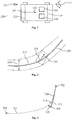
- FIG. 1 a block diagram of an exemplary multi-lane, in particular two-lane, vehicle 100.
- the vehicle 100 comprises a front axle 110 and a rear axle 120.
- a specific front steering angle range 111 can be implemented via a steering device of the front axle 110.
- the vehicle 100 can have a rear wheel steering device with which a certain rear wheel Steering angle range 121 can be implemented.
- the front steering angle range 111 is substantially larger than the rear steering angle range 121.
- a user of the vehicle 100 can activate a reversing assistance system when entering a parking garage, for example.
- a control unit 103 of the vehicle 100 generates a reference trajectory 203 (see FIG Fig. 2 ) and stored in a storage unit 104.
- the reference data relating to a reference trajectory 203 can include position information 201 relating to a reference point 101 of the vehicle 100, wherein the reference point 101 can correspond to the center point of the rear axle 120, for example.
- the reference data in relation to the position of the reference point 101 can be determined with a certain sampling rate (e.g. every 10 cm, 5 cm, or less), so that the course of the reference trajectory 203 in the case of the Forward travel of the vehicle 100 can be described in a precise manner.
- a vehicle 100 has a specific orientation 102 at a specific position while traveling forward.
- Orientation information 202 relating to a rotation or alignment or orientation 102 of the vehicle 100 relative to the reference point 101 can therefore be determined at one position.
- a coverage area 204 in particular a hose, around the reference trajectory 203 can be determined (please refer Fig. 2 ), which indicates the area in which a component (eg part of the bodywork) of the vehicle 100 was located during forward travel.
- the coverage area 204 thus indicates, assuming static obstacles on the reference trajectory 203, the area in which the vehicle 100 can be guided along a reversing trajectory 213 without collision.
- the reversing trajectory 213 can be determined on the basis of the reference trajectory 203 such that the vehicle 100 remains within the coverage area 204 when reversing along the reversing trajectory 213. In this way, assuming static obstacles, a collision-free return trip can be made possible.
- the reference data relating to the reference trajectory 203 ascertained during forward travel can thus include position information 201 for a large number of positions on the reference trajectory 203, which indicates the position of the reference point 101 of the vehicle 100 (e.g. in a Cartesian coordinate system relative to the starting position the reference trajectory 203). Furthermore, the reference data for the plurality of positions can each display orientation information 201 relating to an orientation 102 of the vehicle 100 at the respective position.
- the reference trajectory 203 and the coverage area 204 of the vehicle 100 can thus be described in a precise manner while driving forward.
- the reference data for trajectory segments between a multiplicity of positions can comprise curvature information with regard to a curvature of the respective trajectory segment.
- the reference trajectory 203 can then be described by a sequence of curvature values.
- a course of the reference trajectory 203 can be determined by interpolating the sequence of curvature values (for example by using clothoids).
- the coverage area 204 of the vehicle when driving forward on the reference trajectory 203 can also be determined from the curvature values.
- the determined reversing trajectory 213 can in particular display a steering angle of the steering device of the front axle 110 of the vehicle 100 as a function of the position on the reversing trajectory 213.
- the driver of vehicle 100 can then be assisted in reversing on the basis of the ascertained reversing trajectory 213.
- the steering device of the vehicle 100 can be activated automatically as a function of the reversing trajectory 213 in order to take over the lateral guidance of the vehicle 100.
- the longitudinal guidance of the vehicle 100 in particular the determination of the longitudinal speed and the direction of travel (forward gear or reverse gear) of the vehicle 100, can continue to be carried out by the driver.
- the provision of such a reversing assistant enables a driver of a vehicle 100 to reverse out of a cramped traffic situation (e.g. from a narrow parking garage) in a comfortable manner.
- An automatic steering device of a vehicle 100 typically has a maximum possible steering speed.
- the driving speed at which a vehicle 100 can be guided along the rearward trajectory 213 is typically limited to a specific maximum driving speed depending on the current curvature of the rearward trajectory 213. If the maximum driving speed is exceeded, then the vehicle 100 deviates from the backward trajectory 213. As a result, it can it may be necessary for the reversing assistance system to be switched off. This reduces the availability of the reversing assistance system.
- Fig. 3 illustrates a driving scenario in which a vehicle 100 is to be guided along the reversing trajectory 311 from an end position 302 to a starting position 301 (the respective positions 301, 302 in this document refer to the reference point 101 of the vehicle 100). Due to an excessive driving speed, however, the vehicle 100 can deviate from the reversing trajectory 311 and be guided along the trajectory 312. For the intermediate position 303, it can be detected that the distance 305 between the intermediate position 303 and the originally provided reversing trajectory 311 has reached or exceeded a certain distance threshold value. In response to this, a (visual and / or acoustic) message can be output to the driver of the vehicle 100 via a user interface of the vehicle 100.
- a (visual and / or acoustic) message can be output to the driver of the vehicle 100 via a user interface of the vehicle 100.
- an indication can be output that the vehicle 100 is deviating from the planned reversing trajectory 311 or has already deviated.
- the driver of the vehicle 100 can be requested to stop the vehicle 100, engage a forward gear and, if necessary, drive along a forward trajectory 313 to a reversing position 304 in order to transfer the vehicle 100 back to the planned reversing trajectory 311 . It can thus be proposed that a correction move be carried out in the forward direction in order to bring the vehicle 100 in the forward direction back onto the reversing trajectory 311.
- the forward trajectory 313 can be determined by the control unit 103 of the vehicle 100 on the basis of the position information in relation to the intermediate position 303 and on the basis of the stored data in relation to the reversing trajectory 311. Furthermore, the control unit 103 can be set up to control the steering device of the vehicle 100 on the basis of the determined forward trajectory 313 in order to support the driver of the vehicle 100 with the correction move.
- the driver of the vehicle 100 Upon arrival at the reversing position 304, the driver of the vehicle 100 can be requested to engage a reverse gear in order to resume assisted reversing along the reversing trajectory 311 starting from the reversing position 304.
- the control unit 103 can thus detect that the vehicle 100 is about to leave the target trajectory 311 or has already left it.
- a forward train (in particular a forward trajectory 313) can be planned in order to be able to drive back to the desired trajectory 311 after the forward train.
- the driver can be requested via a user interface of the vehicle 100 (e.g. via a head unit) to stop the vehicle 100 and change gear. After the gear change, an automated forward pull can take place if necessary. The vehicle 100 can then be stopped again and an automated reverse travel on the original trajectory 311 can take place.
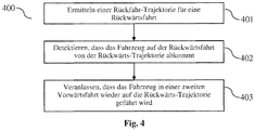
- FIG. 10 shows a flowchart of an exemplary method 400 for driving a vehicle 100 within the scope of a reversing assistance system.
- the method 400 comprises determining 401, on the basis of reference data relating to a first forward travel of the vehicle 100, a reversing trajectory 311 for a reversing from an end position 302 to a starting position 301.
- the reference data can be recorded and have been saved.
- the reference data can in particular display the course of the reference trajectory 203 along which the vehicle 100 was guided during the first forward travel.
- the vehicle 100 was guided longitudinally and transversely by a driver of the vehicle 100 during the first forward travel.
- the steering device of the vehicle 100 may have been actuated manually by the driver of the vehicle 100 during the first forward travel.
- the reversing trajectory 311 can (substantially) correspond to the reference trajectory 203, so that the vehicle 100 can be returned to the starting position 301 on the same path.
- the method 400 further comprises detecting or determining 402 that the vehicle 100 is leaving the reversing trajectory 311 while reversing.
- the steering device of the vehicle 100 can be controlled automatically on the basis of the reversing trajectory 311 by a control unit 103 of the vehicle 100.
- the driving speed can be adjusted by the driver of the vehicle 100. If the driving speed is too high, the vehicle 100 may no longer be able to follow the reversing trajectory 311 (in particular in the case of a tight curve). As a result, it may be necessary to terminate the reversing assistance system.
- the method 400 comprises, in response to the detection 402, causing 403 that the vehicle 100 is guided in a second forward drive to a reversing position 304 which enables the vehicle 100 to be driven again along at least one (remaining) section of the reversing drive.
- the reversing position 304 can lie on the reversing trajectory 311, so that the vehicle 100 can again be guided (transversely) by the reversing assistance system along the reversing trajectory 311 from the reversing position 304 to the starting position 301.
- the measures described in this document can avoid unnecessary deactivation of a reversing assistance system. In this way, the availability of a reversing assistance system can be increased.
Landscapes
- Engineering & Computer Science (AREA)
- Transportation (AREA)
- Mechanical Engineering (AREA)
- Chemical & Material Sciences (AREA)
- Combustion & Propulsion (AREA)
- Automation & Control Theory (AREA)
- Steering Control In Accordance With Driving Conditions (AREA)
- Traffic Control Systems (AREA)
- Control Of Driving Devices And Active Controlling Of Vehicle (AREA)
Claims (11)
- Unité de commande (103) pour un système d'aide à la marche arrière d'un véhicule (100) ; l'unité de commande (103) étant conçue- pour déterminer, sur la base de données de référence relatives à une première marche avant du véhicule (100), une trajectoire de recul (311) pour une marche arrière d'une position finale (302) à une position initiale (301) ;- pour commander un dispositif de direction du véhicule (100) lors de la marche arrière du véhicule (100) en fonction de la trajectoire de recul (311) ; le guidage longitudinal du véhicule (100) lors de la marche arrière étant effectué au moins partiellement par un conducteur du véhicule (100) ;- pour détecter que le véhicule (100) en marche arrière quitte la trajectoire de recul (311) ; et- pour faire en sorte, en réaction à cette situation, que le véhicule (100) soit guidé, dans une deuxième marche avant, à une position de recul (304) qui permet de guider de nouveau le véhicule (100) à la position initiale (301) le long d'au moins une section de la trajectoire de recul (311).
- Unité de commande (103) selon la revendication 1, l'unité de commande (103) étant conçue- pour déterminer une distance (305) d'une position actuelle ou prédite (303) du véhicule (100) à la trajectoire de recul (311) ; et- pour détecter, sur la base de la distance (305), que le véhicule (100) en marche arrière quitte la trajectoire de recul (311).
- Unité de commande (103) selon l'une quelconque des revendications précédentes, l'unité de commande (103) étant conçue pour déterminer une trajectoire d'avancée (313), avec laquelle le véhicule (100) peut être guidé, dans la deuxième marche avant, à la position de recul (304) .
- Unité de commande (103) selon la revendication 3, l'unité de commande (103) étant conçue pour commander un dispositif de direction du véhicule (100) lors de la deuxième marche avant du véhicule (100) en fonction de la trajectoire d'avancée (313).
- Unité de commande (103) selon l'une quelconque des revendications précédentes,- l'unité de commande (103) étant conçue pour émettre une notification à un conducteur du véhicule (100) lorsqu'il a été détecté que le véhicule (100) en marche arrière quitte la trajectoire de recul (311) ; et- la notification indiquant que le conducteur doit immobiliser le véhicule (100) et que le conducteur doit engager un rapport avant pour la deuxième marche avant.
- Unité de commande (103) selon l'une quelconque des revendications précédentes, l'unité de commande (103) étant conçue- pour détecter que le véhicule (100) atteint la position de recul (304) ; et- pour faire en sorte, en réaction à cette situation, qu'un conducteur du véhicule (100) immobilise le véhicule (100) et engage un rapport arrière, afin de poursuivre la marche arrière.
- Unité de commande (103) selon l'une quelconque des revendications précédentes, dans laquelle les données de référence indiquent une trajectoire de référence (203) du véhicule (100) pour la première marche avant de la position initiale (301) à la position finale (302) .
- Unité de commande (103) selon l'une quelconque des revendications précédentes, dans laquelle les données de référence- comprennent des informations de position (201) relatives à une pluralité de positions sur une trajectoire de référence (203) de la première marche avant ; et- comprennent des informations d'orientation (202) relatives à une orientation (102) du véhicule (100) à la pluralité de positions.
- Procédé (400) pour guider un véhicule (100) dans le cadre d'un système d'aide à la marche arrière à guidage transversal automatisé ; le procédé (400) comprenant les étapes consistant :- à déterminer (401), sur la base de données de référence relatives à une première marche avant du véhicule (100), une trajectoire de recul (311) pour une marche arrière d'une position finale (302) à une position initiale (301) ;- à détecter (402) que le véhicule (100) en marche arrière quitte la trajectoire de recul (311) ; le guidage longitudinal du véhicule (100) lors de la marche arrière étant effectué au moins partiellement par un conducteur du véhicule (100) ; et- à faire en sorte (403), en réaction à cette situation, que le véhicule (100) soit guidé, dans une deuxième marche avant, à une position de recul (304) qui permet de guider de nouveau le véhicule (100) à la position initiale (301) le long d'au moins une section de la trajectoire de recul (311).
- Unité de commande (103) pour un système d'aide au conducteur d'un véhicule (100) à guidage transversal automatisé et/ou guidage longitudinal automatisé ; l'unité de commande (103) étant conçue- pour déterminer, sur la base de données de référence relatives à une première marche de référence du véhicule (100), une trajectoire de marche (311) pour une nouvelle marche ;- pour détecter que le véhicule (100) dans la nouvelle marche quitte la trajectoire de marche (311) ; le guidage longitudinal du véhicule (100) lors de la nouvelle marche étant effectué au moins partiellement par un conducteur du véhicule (100) ; et- pour faire en sorte, en réaction à cette situation, que le véhicule (100) soit guidé, dans une marche de correction, à une position de correction (304) qui permet de guider de nouveau le véhicule (100) le long d'au moins une section de la trajectoire de marche (311).
- Procédé pour guider un véhicule dans le cadre d'un système d'aide au conducteur à guidage transversal automatisé et/ou guidage longitudinal automatisé, le procédé comprenant les étapes consistant- à déterminer, sur la base de données de référence relatives à une marche de référence du véhicule (100), une trajectoire de marche (311) pour une nouvelle marche ;- à détecter que le véhicule (100) dans la nouvelle marche quitte la trajectoire de marche (311) ; le guidage longitudinal du véhicule (100) lors de la nouvelle marche étant effectué au moins partiellement par un conducteur du véhicule (100) ; et- à faire en sorte, en réaction à cette situation, que le véhicule (100) soit guidé, dans une marche de correction, à une positon de correction (304) qui permet de guider de nouveau le véhicule (100) le long d'au moins une section de la trajectoire de marche (311) .
Applications Claiming Priority (2)
| Application Number | Priority Date | Filing Date | Title |
|---|---|---|---|
| DE102017200216.6A DE102017200216A1 (de) | 2017-01-09 | 2017-01-09 | Steuereinheit und Verfahren zur Bereitstellung eines Korrekturzugs für ein Rückfahrassistenzsystem |
| PCT/EP2017/081539 WO2018127342A1 (fr) | 2017-01-09 | 2017-12-05 | Unité de commande et procédé permettant de mettre à disposition une manœuvre de correction pour un système d'aide à la marche arrière |
Publications (2)
| Publication Number | Publication Date |
|---|---|
| EP3565757A1 EP3565757A1 (fr) | 2019-11-13 |
| EP3565757B1 true EP3565757B1 (fr) | 2021-07-07 |
Family
ID=60582593
Family Applications (1)
| Application Number | Title | Priority Date | Filing Date |
|---|---|---|---|
| EP17809287.0A Active EP3565757B1 (fr) | 2017-01-09 | 2017-12-05 | Unité de commande et procédé permettant de mettre à disposition une man uvre de correction pour un système d'aide à la marche arrière |
Country Status (5)
| Country | Link |
|---|---|
| US (1) | US10807642B2 (fr) |
| EP (1) | EP3565757B1 (fr) |
| CN (1) | CN109937169B (fr) |
| DE (1) | DE102017200216A1 (fr) |
| WO (1) | WO2018127342A1 (fr) |
Families Citing this family (11)
| Publication number | Priority date | Publication date | Assignee | Title |
|---|---|---|---|---|
| JP7339796B2 (ja) | 2019-07-16 | 2023-09-06 | フォルシアクラリオン・エレクトロニクス株式会社 | 車載処理装置 |
| CN111976717B (zh) * | 2019-11-29 | 2022-07-08 | 长城汽车股份有限公司 | 一种智能泊车方法和装置 |
| CN113064418A (zh) * | 2019-12-13 | 2021-07-02 | 苏州宝时得电动工具有限公司 | 工作地图构建方法、装置、机器人及存储介质 |
| JP7467202B2 (ja) * | 2020-03-31 | 2024-04-15 | 本田技研工業株式会社 | 駐車支援システム |
| DE102020117773A1 (de) * | 2020-07-06 | 2022-01-13 | Valeo Schalter Und Sensoren Gmbh | Verfahren zum ermitteln einer ersatztrajektorie, computerprogrammprodukt, parkassistenzsystem und fahrzeug |
| DE102020211461B4 (de) * | 2020-09-11 | 2022-03-24 | Volkswagen Aktiengesellschaft | Verfahren zum Betreiben eines Rückfahrassistenzsystems für ein Fahrzeug und Rückfahrassistenzsystem |
| CN114516323A (zh) * | 2020-11-20 | 2022-05-20 | 奥迪股份公司 | 一种车辆的倒车辅助方法、装置及车辆 |
| CN112693451B (zh) * | 2021-01-25 | 2022-06-10 | 亿咖通(湖北)技术有限公司 | 高精度倒车轨迹线生成方法、生成系统、泊车方法及系统 |
| CN114475603B (zh) * | 2021-11-19 | 2024-06-14 | 纵目科技(上海)股份有限公司 | 自动倒车方法、系统、设备及计算机可读存储介质 |
| WO2023166738A1 (fr) * | 2022-03-04 | 2023-09-07 | 日産自動車株式会社 | Procédé et dispositif d'aide au stationnement |
| DE102023126551B4 (de) * | 2023-09-28 | 2025-08-28 | Bayerische Motoren Werke Aktiengesellschaft | Verfahren und Fahrerassistenzvorrichtung zur Unterstützung bei der Durchführung eines Rück-Fahrmanövers |
Family Cites Families (18)
| Publication number | Priority date | Publication date | Assignee | Title |
|---|---|---|---|---|
| JP4527644B2 (ja) * | 2005-10-13 | 2010-08-18 | 株式会社デンソー | 車両用ナビゲーション装置 |
| DE102005057267A1 (de) * | 2005-12-01 | 2007-06-06 | Robert Bosch Gmbh | Verfahren und Vorrichtung zur Fahrerzustandserkennung |
| JP2008195263A (ja) * | 2007-02-14 | 2008-08-28 | Denso Corp | 車両用後退支援装置 |
| JP5182545B2 (ja) * | 2007-05-16 | 2013-04-17 | アイシン精機株式会社 | 駐車支援装置 |
| JP4900326B2 (ja) * | 2008-06-10 | 2012-03-21 | 日産自動車株式会社 | 駐車支援装置及び駐車支援方法 |
| DE102008027779A1 (de) * | 2008-06-11 | 2009-12-17 | Valeo Schalter Und Sensoren Gmbh | Verfahren zur Unterstützung eines Fahrers eines Fahrzeugs beim Einparken in eine Parklücke |
| US8207835B2 (en) * | 2008-10-19 | 2012-06-26 | Micha Schwartz | Vehicle safety device |
| CN103079935B (zh) * | 2010-06-04 | 2016-04-13 | 大众汽车有限公司 | 用于辅助汽车泊车的方法和装置 |
| DE102010030208A1 (de) * | 2010-06-17 | 2011-12-22 | Robert Bosch Gmbh | Verfahren zur Unterstützung eines Fahrers eines Kraftfahrzeugs |
| DE102011084943A1 (de) * | 2011-10-21 | 2013-04-25 | Robert Bosch Gmbh | Verfahren und Vorrichtung zur Unterstützung eines Fahrers eines Kraftfahrzeugs |
| KR20140093107A (ko) * | 2013-01-17 | 2014-07-25 | 주식회사 만도 | 출차 제어 시스템 및 그의 출차 제어 방법 |
| DE102013213225A1 (de) * | 2013-07-05 | 2015-01-08 | Robert Bosch Gmbh | Parkassistenzsystem und Verfahren zur Steuerung eines Parkassistenzsystems für ein Fahrzeug |
| JP6303377B2 (ja) * | 2013-10-04 | 2018-04-04 | アイシン精機株式会社 | 駐車支援装置 |
| JP6087805B2 (ja) * | 2013-12-26 | 2017-03-01 | 株式会社東芝 | 運転曲線作成装置、運転支援装置、運転制御装置および運転曲線作成方法 |
| TWI600558B (zh) * | 2014-04-01 | 2017-10-01 | Dynamic lane detection system and method | |
| CN105197010B (zh) * | 2014-06-04 | 2018-03-27 | 长春孔辉汽车科技股份有限公司 | 辅助泊车系统以及辅助泊车控制方法 |
| JP6067635B2 (ja) * | 2014-09-12 | 2017-01-25 | アイシン精機株式会社 | 駐車支援装置 |
| US10403171B2 (en) * | 2016-11-17 | 2019-09-03 | Jerome Toliver | System providing customized remedial training for drivers |
-
2017
- 2017-01-09 DE DE102017200216.6A patent/DE102017200216A1/de not_active Withdrawn
- 2017-12-05 EP EP17809287.0A patent/EP3565757B1/fr active Active
- 2017-12-05 CN CN201780067220.8A patent/CN109937169B/zh active Active
- 2017-12-05 WO PCT/EP2017/081539 patent/WO2018127342A1/fr not_active Ceased
-
2019
- 2019-07-08 US US16/504,404 patent/US10807642B2/en active Active
Also Published As
| Publication number | Publication date |
|---|---|
| EP3565757A1 (fr) | 2019-11-13 |
| DE102017200216A1 (de) | 2018-07-12 |
| US20190329822A1 (en) | 2019-10-31 |
| US10807642B2 (en) | 2020-10-20 |
| CN109937169B (zh) | 2021-12-21 |
| CN109937169A (zh) | 2019-06-25 |
| WO2018127342A1 (fr) | 2018-07-12 |
Similar Documents
| Publication | Publication Date | Title |
|---|---|---|
| EP3565757B1 (fr) | Unité de commande et procédé permettant de mettre à disposition une man uvre de correction pour un système d'aide à la marche arrière | |
| EP3565756B1 (fr) | Dispositif et procédé de détermination d'une trajectoire pour un système d'aide à la marche arrière | |
| EP3177504B1 (fr) | Procédé servant à manoeuvrer au moins de manière semi-autonome un véhicule automobile, système d'assistance au conducteur ainsi que véhicule automobile | |
| EP2768718B1 (fr) | Procédé et dispositif d'assistance à un conducteur d'un véhicule automobile | |
| EP2780213B1 (fr) | Procédé et dispositif permettant de définir une stratégie de sortie d'une place de stationnement | |
| EP2644477B1 (fr) | Dispositifs d'assistance et procédé de fonctionnement d'un dispositif d'assistance pour le pilotage d'un véhicule de traction avec remorque | |
| DE102017219876A1 (de) | Steuereinheit und Verfahren zum Führen eines Fahrzeugs mit Anhänger | |
| WO2009121534A1 (fr) | Procédé et dispositif d'assistance au conducteur d'un véhicule automobile lors de la sortie d'une place de stationnement | |
| DE102008000575A1 (de) | Verfahren und Vorrichtung zum Einparken eines Kraftfahrzeugs in eine Parklücke mittels eines Einparkassistenten | |
| EP2517190A1 (fr) | Procédé de stationnement automatique, en marche avant, dans des places libres de stationnement en épi ou en bataille | |
| DE102017208383B4 (de) | Dynamisches Einparken mittels Parkassistenzsystem | |
| DE102014013219A1 (de) | Assistenzsystem zum Rangieren eines Gespanns sowie Verfahren zum Betreiben eines solchen Assistenzsystems | |
| EP1048506B1 (fr) | Système pour la régulation de la déviation latérale entre deux véhicules | |
| DE102017200218A1 (de) | Steuereinheit und Verfahren zur Berücksichtigung von Hindernissen bei einem Rückfahrassistenzsystem | |
| DE102018212060A1 (de) | Verfahren zum Führen eines Fahrzeugs von einer Startposition zu einer Zielposition | |
| EP2345572A1 (fr) | Procédé destiné à assister un conducteur de véhicule automobile | |
| DE102016121465A1 (de) | Verfahren zum Manövrieren eines Kraftfahrzeugs unter Berücksichtigung von in einer Aufzeichnungsphase bestimmten Positionswerten, Fahrerassistenzsystem sowie Kraftfahrzeug | |
| DE102017216088A1 (de) | Steuersystem zum Lenken eines Zugfahrzeuges mit einem Anhänger | |
| DE102013013568A1 (de) | Spurhalteassistenzsystem und Verfahren zum Spurhalten eines Kraftfahrzeugs | |
| DE102016120677A1 (de) | Verfahren zum Betreiben eines Fahrerassistenzsystems zum Durchführen eines zumindest semi-autonomen Einparkmanövers eines Kraftfahrzeugs unter Berücksichtigung von Eingriffen des Fahrers, Fahrerassistenzsystem sowie Kraftfahrzeug | |
| DE102008014969B4 (de) | Verfahren zur Einparkunterstützung | |
| DE102017200215A1 (de) | Steuereinheit und Verfahren zur Ermittlung einer Rückfahr-Trajektorie für ein Rückfahrassistenzsystem | |
| DE102015118584A1 (de) | Verfahren zum zumindest semi-autonomen Manövrieren eines Kraftfahrzeugs mit Bestimmung eines Zielwinkels für die Ausfahrt aus einer Parklücke, Fahrerassistenzsystem sowie Kraftfahrzeug | |
| DE102017208473A1 (de) | Verfahren und Steuereinheit zur Querführung eines Fahrzeugs | |
| DE102013010729B4 (de) | Verfahren zum Abbrechen eines automatischen Fahrmodus eines Kraftfahrzeugs, Fahrerassistenzeinrichtung und Kraftfahrzeug |
Legal Events
| Date | Code | Title | Description |
|---|---|---|---|
| STAA | Information on the status of an ep patent application or granted ep patent |
Free format text: STATUS: UNKNOWN |
|
| STAA | Information on the status of an ep patent application or granted ep patent |
Free format text: STATUS: THE INTERNATIONAL PUBLICATION HAS BEEN MADE |
|
| PUAI | Public reference made under article 153(3) epc to a published international application that has entered the european phase |
Free format text: ORIGINAL CODE: 0009012 |
|
| STAA | Information on the status of an ep patent application or granted ep patent |
Free format text: STATUS: REQUEST FOR EXAMINATION WAS MADE |
|
| 17P | Request for examination filed |
Effective date: 20190226 |
|
| AK | Designated contracting states |
Kind code of ref document: A1 Designated state(s): AL AT BE BG CH CY CZ DE DK EE ES FI FR GB GR HR HU IE IS IT LI LT LU LV MC MK MT NL NO PL PT RO RS SE SI SK SM TR |
|
| AX | Request for extension of the european patent |
Extension state: BA ME |
|
| DAV | Request for validation of the european patent (deleted) | ||
| DAX | Request for extension of the european patent (deleted) | ||
| GRAP | Despatch of communication of intention to grant a patent |
Free format text: ORIGINAL CODE: EPIDOSNIGR1 |
|
| STAA | Information on the status of an ep patent application or granted ep patent |
Free format text: STATUS: GRANT OF PATENT IS INTENDED |
|
| INTG | Intention to grant announced |
Effective date: 20210326 |
|
| GRAS | Grant fee paid |
Free format text: ORIGINAL CODE: EPIDOSNIGR3 |
|
| GRAA | (expected) grant |
Free format text: ORIGINAL CODE: 0009210 |
|
| STAA | Information on the status of an ep patent application or granted ep patent |
Free format text: STATUS: THE PATENT HAS BEEN GRANTED |
|
| AK | Designated contracting states |
Kind code of ref document: B1 Designated state(s): AL AT BE BG CH CY CZ DE DK EE ES FI FR GB GR HR HU IE IS IT LI LT LU LV MC MK MT NL NO PL PT RO RS SE SI SK SM TR |
|
| REG | Reference to a national code |
Ref country code: GB Ref legal event code: FG4D Free format text: NOT ENGLISH |
|
| REG | Reference to a national code |
Ref country code: AT Ref legal event code: REF Ref document number: 1408330 Country of ref document: AT Kind code of ref document: T Effective date: 20210715 |
|
| REG | Reference to a national code |
Ref country code: DE Ref legal event code: R096 Ref document number: 502017010874 Country of ref document: DE |
|
| REG | Reference to a national code |
Ref country code: IE Ref legal event code: FG4D Free format text: LANGUAGE OF EP DOCUMENT: GERMAN |
|
| REG | Reference to a national code |
Ref country code: LT Ref legal event code: MG9D |
|
| REG | Reference to a national code |
Ref country code: NL Ref legal event code: MP Effective date: 20210707 |
|
| PG25 | Lapsed in a contracting state [announced via postgrant information from national office to epo] |
Ref country code: RS Free format text: LAPSE BECAUSE OF FAILURE TO SUBMIT A TRANSLATION OF THE DESCRIPTION OR TO PAY THE FEE WITHIN THE PRESCRIBED TIME-LIMIT Effective date: 20210707 Ref country code: SE Free format text: LAPSE BECAUSE OF FAILURE TO SUBMIT A TRANSLATION OF THE DESCRIPTION OR TO PAY THE FEE WITHIN THE PRESCRIBED TIME-LIMIT Effective date: 20210707 Ref country code: HR Free format text: LAPSE BECAUSE OF FAILURE TO SUBMIT A TRANSLATION OF THE DESCRIPTION OR TO PAY THE FEE WITHIN THE PRESCRIBED TIME-LIMIT Effective date: 20210707 Ref country code: FI Free format text: LAPSE BECAUSE OF FAILURE TO SUBMIT A TRANSLATION OF THE DESCRIPTION OR TO PAY THE FEE WITHIN THE PRESCRIBED TIME-LIMIT Effective date: 20210707 Ref country code: ES Free format text: LAPSE BECAUSE OF FAILURE TO SUBMIT A TRANSLATION OF THE DESCRIPTION OR TO PAY THE FEE WITHIN THE PRESCRIBED TIME-LIMIT Effective date: 20210707 Ref country code: NL Free format text: LAPSE BECAUSE OF FAILURE TO SUBMIT A TRANSLATION OF THE DESCRIPTION OR TO PAY THE FEE WITHIN THE PRESCRIBED TIME-LIMIT Effective date: 20210707 Ref country code: NO Free format text: LAPSE BECAUSE OF FAILURE TO SUBMIT A TRANSLATION OF THE DESCRIPTION OR TO PAY THE FEE WITHIN THE PRESCRIBED TIME-LIMIT Effective date: 20211007 Ref country code: PT Free format text: LAPSE BECAUSE OF FAILURE TO SUBMIT A TRANSLATION OF THE DESCRIPTION OR TO PAY THE FEE WITHIN THE PRESCRIBED TIME-LIMIT Effective date: 20211108 Ref country code: BG Free format text: LAPSE BECAUSE OF FAILURE TO SUBMIT A TRANSLATION OF THE DESCRIPTION OR TO PAY THE FEE WITHIN THE PRESCRIBED TIME-LIMIT Effective date: 20211007 Ref country code: LT Free format text: LAPSE BECAUSE OF FAILURE TO SUBMIT A TRANSLATION OF THE DESCRIPTION OR TO PAY THE FEE WITHIN THE PRESCRIBED TIME-LIMIT Effective date: 20210707 |
|
| PG25 | Lapsed in a contracting state [announced via postgrant information from national office to epo] |
Ref country code: PL Free format text: LAPSE BECAUSE OF FAILURE TO SUBMIT A TRANSLATION OF THE DESCRIPTION OR TO PAY THE FEE WITHIN THE PRESCRIBED TIME-LIMIT Effective date: 20210707 Ref country code: LV Free format text: LAPSE BECAUSE OF FAILURE TO SUBMIT A TRANSLATION OF THE DESCRIPTION OR TO PAY THE FEE WITHIN THE PRESCRIBED TIME-LIMIT Effective date: 20210707 Ref country code: GR Free format text: LAPSE BECAUSE OF FAILURE TO SUBMIT A TRANSLATION OF THE DESCRIPTION OR TO PAY THE FEE WITHIN THE PRESCRIBED TIME-LIMIT Effective date: 20211008 |
|
| REG | Reference to a national code |
Ref country code: DE Ref legal event code: R097 Ref document number: 502017010874 Country of ref document: DE |
|
| PG25 | Lapsed in a contracting state [announced via postgrant information from national office to epo] |
Ref country code: DK Free format text: LAPSE BECAUSE OF FAILURE TO SUBMIT A TRANSLATION OF THE DESCRIPTION OR TO PAY THE FEE WITHIN THE PRESCRIBED TIME-LIMIT Effective date: 20210707 |
|
| PLBE | No opposition filed within time limit |
Free format text: ORIGINAL CODE: 0009261 |
|
| STAA | Information on the status of an ep patent application or granted ep patent |
Free format text: STATUS: NO OPPOSITION FILED WITHIN TIME LIMIT |
|
| PG25 | Lapsed in a contracting state [announced via postgrant information from national office to epo] |
Ref country code: SM Free format text: LAPSE BECAUSE OF FAILURE TO SUBMIT A TRANSLATION OF THE DESCRIPTION OR TO PAY THE FEE WITHIN THE PRESCRIBED TIME-LIMIT Effective date: 20210707 Ref country code: SK Free format text: LAPSE BECAUSE OF FAILURE TO SUBMIT A TRANSLATION OF THE DESCRIPTION OR TO PAY THE FEE WITHIN THE PRESCRIBED TIME-LIMIT Effective date: 20210707 Ref country code: RO Free format text: LAPSE BECAUSE OF FAILURE TO SUBMIT A TRANSLATION OF THE DESCRIPTION OR TO PAY THE FEE WITHIN THE PRESCRIBED TIME-LIMIT Effective date: 20210707 Ref country code: EE Free format text: LAPSE BECAUSE OF FAILURE TO SUBMIT A TRANSLATION OF THE DESCRIPTION OR TO PAY THE FEE WITHIN THE PRESCRIBED TIME-LIMIT Effective date: 20210707 Ref country code: CZ Free format text: LAPSE BECAUSE OF FAILURE TO SUBMIT A TRANSLATION OF THE DESCRIPTION OR TO PAY THE FEE WITHIN THE PRESCRIBED TIME-LIMIT Effective date: 20210707 Ref country code: AL Free format text: LAPSE BECAUSE OF FAILURE TO SUBMIT A TRANSLATION OF THE DESCRIPTION OR TO PAY THE FEE WITHIN THE PRESCRIBED TIME-LIMIT Effective date: 20210707 |
|
| 26N | No opposition filed |
Effective date: 20220408 |
|
| PG25 | Lapsed in a contracting state [announced via postgrant information from national office to epo] |
Ref country code: MC Free format text: LAPSE BECAUSE OF FAILURE TO SUBMIT A TRANSLATION OF THE DESCRIPTION OR TO PAY THE FEE WITHIN THE PRESCRIBED TIME-LIMIT Effective date: 20210707 Ref country code: IT Free format text: LAPSE BECAUSE OF FAILURE TO SUBMIT A TRANSLATION OF THE DESCRIPTION OR TO PAY THE FEE WITHIN THE PRESCRIBED TIME-LIMIT Effective date: 20210707 |
|
| REG | Reference to a national code |
Ref country code: CH Ref legal event code: PL |
|
| REG | Reference to a national code |
Ref country code: BE Ref legal event code: MM Effective date: 20211231 |
|
| PG25 | Lapsed in a contracting state [announced via postgrant information from national office to epo] |
Ref country code: LU Free format text: LAPSE BECAUSE OF NON-PAYMENT OF DUE FEES Effective date: 20211205 Ref country code: IE Free format text: LAPSE BECAUSE OF NON-PAYMENT OF DUE FEES Effective date: 20211205 |
|
| PG25 | Lapsed in a contracting state [announced via postgrant information from national office to epo] |
Ref country code: BE Free format text: LAPSE BECAUSE OF NON-PAYMENT OF DUE FEES Effective date: 20211231 |
|
| PG25 | Lapsed in a contracting state [announced via postgrant information from national office to epo] |
Ref country code: LI Free format text: LAPSE BECAUSE OF NON-PAYMENT OF DUE FEES Effective date: 20211231 Ref country code: CH Free format text: LAPSE BECAUSE OF NON-PAYMENT OF DUE FEES Effective date: 20211231 |
|
| P01 | Opt-out of the competence of the unified patent court (upc) registered |
Effective date: 20230424 |
|
| PG25 | Lapsed in a contracting state [announced via postgrant information from national office to epo] |
Ref country code: CY Free format text: LAPSE BECAUSE OF FAILURE TO SUBMIT A TRANSLATION OF THE DESCRIPTION OR TO PAY THE FEE WITHIN THE PRESCRIBED TIME-LIMIT Effective date: 20210707 |
|
| PG25 | Lapsed in a contracting state [announced via postgrant information from national office to epo] |
Ref country code: HU Free format text: LAPSE BECAUSE OF FAILURE TO SUBMIT A TRANSLATION OF THE DESCRIPTION OR TO PAY THE FEE WITHIN THE PRESCRIBED TIME-LIMIT; INVALID AB INITIO Effective date: 20171205 |
|
| REG | Reference to a national code |
Ref country code: AT Ref legal event code: MM01 Ref document number: 1408330 Country of ref document: AT Kind code of ref document: T Effective date: 20221205 |
|
| PG25 | Lapsed in a contracting state [announced via postgrant information from national office to epo] |
Ref country code: AT Free format text: LAPSE BECAUSE OF NON-PAYMENT OF DUE FEES Effective date: 20221205 |
|
| PG25 | Lapsed in a contracting state [announced via postgrant information from national office to epo] |
Ref country code: MK Free format text: LAPSE BECAUSE OF FAILURE TO SUBMIT A TRANSLATION OF THE DESCRIPTION OR TO PAY THE FEE WITHIN THE PRESCRIBED TIME-LIMIT Effective date: 20210707 Ref country code: AT Free format text: LAPSE BECAUSE OF NON-PAYMENT OF DUE FEES Effective date: 20221205 |
|
| PG25 | Lapsed in a contracting state [announced via postgrant information from national office to epo] |
Ref country code: TR Free format text: LAPSE BECAUSE OF FAILURE TO SUBMIT A TRANSLATION OF THE DESCRIPTION OR TO PAY THE FEE WITHIN THE PRESCRIBED TIME-LIMIT Effective date: 20210707 |
|
| PG25 | Lapsed in a contracting state [announced via postgrant information from national office to epo] |
Ref country code: MT Free format text: LAPSE BECAUSE OF FAILURE TO SUBMIT A TRANSLATION OF THE DESCRIPTION OR TO PAY THE FEE WITHIN THE PRESCRIBED TIME-LIMIT Effective date: 20210707 |
|
| PGFP | Annual fee paid to national office [announced via postgrant information from national office to epo] |
Ref country code: DE Payment date: 20251203 Year of fee payment: 9 |
|
| PGFP | Annual fee paid to national office [announced via postgrant information from national office to epo] |
Ref country code: GB Payment date: 20251218 Year of fee payment: 9 |
|
| PGFP | Annual fee paid to national office [announced via postgrant information from national office to epo] |
Ref country code: FR Payment date: 20251217 Year of fee payment: 9 |
|
| PGFP | Annual fee paid to national office [announced via postgrant information from national office to epo] |
Ref country code: AT Payment date: 20260410 Year of fee payment: 5 |