EP3565776B1 - Installation de transport de récipients avec un élément de trajectoire échangeable - Google Patents
Installation de transport de récipients avec un élément de trajectoire échangeable Download PDFInfo
- Publication number
- EP3565776B1 EP3565776B1 EP17791065.0A EP17791065A EP3565776B1 EP 3565776 B1 EP3565776 B1 EP 3565776B1 EP 17791065 A EP17791065 A EP 17791065A EP 3565776 B1 EP3565776 B1 EP 3565776B1
- Authority
- EP
- European Patent Office
- Prior art keywords
- friction
- transport system
- track element
- container transport
- track
- Prior art date
- Legal status (The legal status is an assumption and is not a legal conclusion. Google has not performed a legal analysis and makes no representation as to the accuracy of the status listed.)
- Active
Links
Images




Classifications
-
- B—PERFORMING OPERATIONS; TRANSPORTING
- B65—CONVEYING; PACKING; STORING; HANDLING THIN OR FILAMENTARY MATERIAL
- B65G—TRANSPORT OR STORAGE DEVICES, e.g. CONVEYORS FOR LOADING OR TIPPING, SHOP CONVEYOR SYSTEMS OR PNEUMATIC TUBE CONVEYORS
- B65G21/00—Supporting or protective framework or housings for endless load-carriers or traction elements of belt or chain conveyors
- B65G21/20—Means incorporated in, or attached to, framework or housings for guiding load-carriers, traction elements or loads supported on moving surfaces
- B65G21/2045—Mechanical means for guiding or retaining the load on the load-carrying surface
- B65G21/2063—Mechanical means for guiding or retaining the load on the load-carrying surface comprising elements not movable in the direction of load-transport
- B65G21/2072—Laterial guidance means
-
- B—PERFORMING OPERATIONS; TRANSPORTING
- B65—CONVEYING; PACKING; STORING; HANDLING THIN OR FILAMENTARY MATERIAL
- B65G—TRANSPORT OR STORAGE DEVICES, e.g. CONVEYORS FOR LOADING OR TIPPING, SHOP CONVEYOR SYSTEMS OR PNEUMATIC TUBE CONVEYORS
- B65G21/00—Supporting or protective framework or housings for endless load-carriers or traction elements of belt or chain conveyors
- B65G21/02—Supporting or protective framework or housings for endless load-carriers or traction elements of belt or chain conveyors consisting essentially of struts, ties, or like structural elements
- B65G21/06—Supporting or protective framework or housings for endless load-carriers or traction elements of belt or chain conveyors consisting essentially of struts, ties, or like structural elements constructed to facilitate rapid assembly or dismantling
-
- B—PERFORMING OPERATIONS; TRANSPORTING
- B65—CONVEYING; PACKING; STORING; HANDLING THIN OR FILAMENTARY MATERIAL
- B65G—TRANSPORT OR STORAGE DEVICES, e.g. CONVEYORS FOR LOADING OR TIPPING, SHOP CONVEYOR SYSTEMS OR PNEUMATIC TUBE CONVEYORS
- B65G2207/00—Indexing codes relating to constructional details, configuration and additional features of a handling device, e.g. Conveyors
- B65G2207/26—Hygienic features, e.g. easy to sanitize
-
- B—PERFORMING OPERATIONS; TRANSPORTING
- B65—CONVEYING; PACKING; STORING; HANDLING THIN OR FILAMENTARY MATERIAL
- B65G—TRANSPORT OR STORAGE DEVICES, e.g. CONVEYORS FOR LOADING OR TIPPING, SHOP CONVEYOR SYSTEMS OR PNEUMATIC TUBE CONVEYORS
- B65G2207/00—Indexing codes relating to constructional details, configuration and additional features of a handling device, e.g. Conveyors
- B65G2207/30—Modular constructions
-
- B—PERFORMING OPERATIONS; TRANSPORTING
- B65—CONVEYING; PACKING; STORING; HANDLING THIN OR FILAMENTARY MATERIAL
- B65G—TRANSPORT OR STORAGE DEVICES, e.g. CONVEYORS FOR LOADING OR TIPPING, SHOP CONVEYOR SYSTEMS OR PNEUMATIC TUBE CONVEYORS
- B65G47/00—Article or material-handling devices associated with conveyors; Methods employing such devices
- B65G47/74—Feeding, transfer, or discharging devices of particular kinds or types
- B65G47/84—Star-shaped wheels or devices having endless travelling belts or chains, the wheels or devices being equipped with article-engaging elements
Definitions
- the invention relates to a container transport system with an exchangeable track element with an upper and lower track element level for guiding containers.
- Container transport systems are used, for example, in container treatment systems and guide the containers to be treated, for example beverage containers, through the container treatment system.
- it can have both rigid track elements, i.e. track elements on which the containers slide, or rotary track elements, i.e. track elements in which the containers are transported.
- the web elements should also be as insensitive as possible to leaking beverages or the resulting glass splinters.
- the track elements In order to avoid unnecessary downtimes of the container treatment system due to a change of track element or cleaning, the track elements should be able to be replaced particularly quickly and easily.
- the fastening devices used for this purpose must also be particularly easy to clean without a great deal of time and still ensure that the components are securely fastened during operation of the container treatment plant.
- WO 2015/104125 discloses a container transport system according to the preamble of claim 1.
- the invention is therefore based on the object of providing a container transport system with an improved connecting device for the track elements.
- the invention is based on the finding that the web element must be coupled to the container transport system via friction devices that Connect track element with the container transport system, which are designed as simply as possible in order to enable quick and easy disassembly or assembly of the track element and particularly easy cleaning of the components, and which are also braced and / or pretensioned to loosen the friction devices and thus to prevent the web elements due to vibrations occurring during operation or due to wear and tear.
- the friction device provided for the coupling must be particularly easy to reach and, in particular, operable by hand, since the tight installation spaces often make it significantly more difficult to use additional tools.
- track elements are understood to mean, for example, format parts that are matched to individual beverage containers. This includes rigid format parts along which the containers slide. These can be both linear, i.e. straight-line elements, as well as path elements with curvature. Track elements are also understood to mean rotary elements that bring about (active) transport of the container. These include, for example, driven star-shaped track elements.
- the track elements mostly have several track element planes that come into contact with the containers, in particular beverage bottles or beverage cans.
- Track element planes are mostly understood to be flat components that are configured on an outer edge for contact with the beverage container.
- the invention also expressly includes track elements which, in addition to the lower and upper track element levels, also have one or more middle track element levels.
- the rotatability of the friction device is understood to mean that the friction device can be rotated about its own axis of rotation, which is aligned in particular in the Z-direction of the track element.
- the friction device In the mounted state, for example on the web element, the friction device can assume at least two different positions, namely a first position and a second position. In this case, the friction device be arranged in particular in such a way that it can be rotated back and forth at least between the first and second position.
- the first position is understood to mean, in particular, a locking position in which the friction device prevents the track element from being lifted off the carrier element in the direction of the axis of rotation of the friction device. Accordingly, it is also not possible to mount the web element with a friction device on the carrier element in a first position.
- there is a torsional stress or torque on the friction device i.e. a torsional stress acting about its own axis of rotation (Z-axis), which acts at least in the section of the friction device with which the lower track element is fastened to the carrier element .
- the second position is understood as an unlocked position in which the track element can be assembled and/or dismantled on the carrier element, i.e. a mounted track element can be removed from the carrier element in the second position in the direction of the axis of rotation (Z-axis direction).
- the friction device can also be mounted freely, i.e. rotatably through an angle of 360°, whereby it can assume at least the first and second position.
- the fixation of the lower track element plane on the carrier element by means of the friction device is particularly positive.
- the friction device exerts a clamping pressure on the lower web element level and the carrier element.
- a carrier element is understood in particular as a component of the beverage transport system on which a track element is supported at least in the Z-axis direction, ie vertically.
- the carrier element can be flat, for example in the form of a plate.
- the carrier element can also comprise a number of components. So it can, for example, have a flat or plate-shaped component designed to rest on the track element, for example a support clip, which is connected to a support pin which is provided for attachment to a container treatment system.
- a tensioning device is understood to be a device that generates torsional stress on the friction device, with the torsional stress generating a torque that counteracts a movement from the first position to the second position of a section of the friction device that fixes the lower track element plane to the carrier element, for example of the friction foot.
- the tensioning device thus generates a pressing pressure or a pretension in the direction of the first position of the friction device on the section of the friction device that fixes the lower web element level on the carrier element. This torque thus causes the friction body to rest permanently and without play on the carrier element.
- the grating device is particularly preferably designed in several parts and, in addition to the grating body, has a grating head and/or grating foot.
- the friction body and the friction foot are preferably, but not necessarily, formed in one piece and are formed, for example, from a flat workpiece, such as a sheet metal, which makes it particularly easy to clean.
- the friction head preferably forms a gripping element. It can be designed to be plugged onto a free end of the friction body opposite the friction foot.
- the reaming head is designed in particular as an injection molded part made of plastic, for example.
- the invention provides that the tensioning device comprises at least one spring element for generating or maintaining the torsional stress.
- the friction device 6 is rotated by the operator from the second to the first position.
- the dimensions of the components are selected so that the upper friction lugs 33, 32 come to rest against at least one contact surface 46a, 46b of the support clasp 46 during this rotary movement before the latching elements—with further rotary movement of the anti-twist device 30—latch into the latching receptacles.
- the angle of rotation of the locking elements engaged in the locking receptacles during locking is greater than the angle of rotation of the lower and upper friction lugs 33, 32.
- the angles of rotation preferably differ only slightly.
- the at least one spring element provided undergoes elastic deformation by means of which a torsional stress or prestress is generated, this acting on the contact surface of the lower friction lug starting from the snap-in receptacles via the snap-in elements, the first friction device, the friction body and the friction lugs.
- the at least one spring element is formed inside the friction body 12 .
- the dimensions of the length and/or the cross section of the friction body are selected such that an elastic rotation of the lower end of the friction body relative to its upper end by a specific, desired angle of rotation requires a specific desired torque and thus generates a corresponding torsional stress or prestress.
- the cross section of the friction body can have areas with a taper, which allows a larger angle of rotation with an identical torque.
- the friction body can also consist of at least two parts, with the two parts of the friction body being connected by means of a further element of a different material, for example a plastic material.
- the further element has greater elasticity than the at least two parts of the friction body, since a larger angle of rotation can easily be achieved in this way with a constant torque.
- the at least one spring element can also be formed inside the friction foot 13 .
- the dimensions of the friction foot 13 can also be chosen such that the elastic torsional deformation required for the formation of a spring element can take place within the friction foot 13 .
- the at least one spring element can also be formed inside the friction head 11 .
- the spring element is particularly preferably attached to a base body of the friction head and a bearing guide of the friction head, so that when the torsion is generated in the spring element, the base body runs through a larger angle of rotation compared to the bearing guide.
- Two spring elements are particularly preferably arranged on the friction head. These can, for example, be arranged diametrically to one another about a longitudinal axis, for example the axis of rotation.
- the spring element is arranged at a distance from a free end of the friction body. This means that a gap is formed between the spring element and the free end of the friction body, which is arranged in the friction head.
- each of the spring elements accordingly has a gap to the free end of the friction body. In addition to the improved cleanability of the reaming head, this also makes it easier for the spring elements to twist.
- the friction device particularly preferably has an upper friction lug and a lower friction lug on, wherein the upper friction lug is designed and arranged for engagement on the upper side of the lower web element plane and the lower friction lug for engagement on the underside of the carrier element.
- a friction lug is understood to mean a projection protruding from the friction device (or the friction body/friction foot) or a recess made in the friction device (or the friction body/friction foot).
- the upper friction lug is designed and arranged such that in the first position it engages (is in contact) with a portion aligned with the lower friction lug on the upper side of the lower web element, while the lower friction lug is designed and aligned such that it engages with a Section attacks on the underside of the support element, or is in contact with it or is supported on this.
- the section on the underside of the carrier element is preferably aligned with the friction lug and is designed in such a way that the friction lug can be rotated or slid continuously against the underside arranged at an angle to the horizontal.
- the friction lugs are in particular designed in one piece with the friction body or friction foot.
- the lower web element level and the carrier element which are both plate-shaped, i.e. flat, are thus fixed between the upper and lower friction lugs.
- the lower track element level and the carrier element can be clamped together by the friction lugs. Consequently, the fixation between the carrier element and the lower web element level is designed, for example, as a form-fitting connection.
- a contact surface that is oriented obliquely to the axis of rotation Z of the friction device is arranged on the underside of the carrier element for contacting the lower friction nose of the friction foot.
- An inclined contact surface is understood to mean a section of the carrier element which is designed to make contact with a contact surface on the lower friction lugs.
- the carrier element also has two contact surfaces, one of the contact surfaces extending vertically upwards in the direction of the grating head and the other contact surface in the opposite direction vertically downwards, ie in the direction of the contact surface of the grating lug.
- a helical surface or a course of the surface similar to a thread can also be provided. Overall, these contact surfaces can also be inclined to the horizontal, or else be arranged horizontally.
- the ratio of the directional components transverse to the direction of the axis of rotation Z (horizontal) and in the direction of the axis of rotation Z (vertical) is at least 2:1, preferably at least 5:1, in the case of the inclined contact surface. That is, the angle between the axis of rotation direction Z and the inclined surface is, for example, between 93° and 100° and between 87° and 80°.
- chamfers can be arranged on the edges of the sloping surfaces, it being noted that a sloping contact surface does not mean a chamfer.
- the friction device has an anti-twist device against unintentional twisting about the axis of rotation.
- the anti-twist device is arranged in particular on the friction head and prevents the friction device from twisting both in the first position and in the second position.
- the anti-twist device particularly preferably has a latching element with a latching element receptacle designed to correspond thereto.
- the locking element can be arranged, for example, in the area of a locking bolt arranged on the locking head, while the locking element receptacle is designed in particular as a recess in the area of the upper track element plane.
- the anti-rotation device can be designed in addition to the tensioning device, the tensioning device being arranged in addition to the anti-rotation device and, as already explained above, exerting torsional stress on the section (e.g. friction foot) of the friction device clamping the carrier element and the lower track element plane.
- the secure engagement of the anti-twist device securely fixes the elastic (rotational) deformation of the at least one spring element generated by the operating personnel, whereby the desired permanent prestressing that presses the friction device in the direction of the first position is generated or maintained.
- a further embodiment of the invention provides for the arrangement of at least one piece of protection against fragments on the friction device, for example in the area above the friction foot and/or above the bearing guide.
- the shard protection prevents glass shards from destroyed glass containers from penetrating the area of the storage unit and/or the area of the squeegee.
- the shard guard also centers and supports the lower part of the grating device.
- a pull-out safeguard for fixing the friction device on the web element is also arranged in the direction of the axis of rotation.
- the pull-out safeguard can be designed as a component on the friction device which can prevent the friction device from being released or removed from the web element in the direction of the axis of rotation and in particular upwards.
- the pull-out protection has, for example, at least one locking bolt which has a support surface, for example a locking lug, which is in contact with the underside of the upper track element level in a locking position.
- two or more locking bars can also be arranged, for example, which are arranged, for example, diametrically around the axis of rotation of the friction device on the friction device.
- the blocking position is understood to mean the position in which the removal of the friction device is blocked at least upwards in the direction of the axis of rotation by the track element. Accordingly, the friction device can be removed from the web element in the second position and in the release position.
- the pull-out safeguard and/or in particular the locking bar can be formed, for example, in one piece with the friction device, in particular in one piece with the friction head.
- the pull-out protection is therefore for particularly quick disassembly the friction device from the web element, for example to clean them, in particular designed as a quick-release fastener. After removing the grating head, the remaining components of the grating device can also be removed without tools, which also makes cleaning easier.
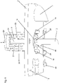
- the track element 1 shows schematically in a perspective view a partial section of a rigid track element 1 for guiding containers (not shown here).
- the track element 1 has an upper track element level 2 and a lower track element level 3, which are connected to one another via spacers 4.
- a support element 5 designed for placing the track element 1 is shown below the track element 1 .
- a friction device 6 is arranged, which is designed to fix the web element 1 on the carrier element 5 in a direction of the axis of rotation Z upwards (represented by an arrow).
- the friction device 6 is shown in its first position, i.e. in the arrangement shown the web element 1 cannot be placed on the carrier element 5.
- the carrier element 5 is designed in several parts and has a carrier pin 47 , which is round in this case, and a carrier clip 7 arranged on the carrier pin 47 .
- the upper side 49 of the carrier clasp 7 is designed to rest against an underside 8 (see figure 7 ) of the lower track element level 3 is provided.
- the carrier clip 7 has two receiving legs 9a, 9b.
- the grating device 6 has a grating head 11 , a grating body 12 and a grating foot 13 .
- the friction head 11 is pushed onto the friction body 12 and can be pulled off/put on the friction body 12 for disassembly or assembly of the friction device 6 .
- a clamping device 23 for applying a torsional stress to the friction body 12 is also arranged on the friction head 11 .
- tabs 44 are arranged on the friction head 11 for better handling during the rotary movement of the friction device 6 .
- the tabs 44 are flush with the gripping surfaces 50 of the friction head 11 (see figure 2 ), but can also protrude at an angle from the gripping surfaces, for example.
- FIG. 1 Furthermore shows figure 1 a positioning device 40 with a locating bolt 41 and a bolt receptacle 42 arranged for accommodating the locating bolt 41 in the lower track element level 3 and a railing support 48 for accommodating a guide railing (not shown here) along which the containers can slide during transport.
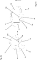
- Figures 2 and 3 show the friction device 6 with the friction head 11, the friction body 12 and the friction foot 13.
- the friction body 12 and the friction foot 13 are formed in one piece, formed here from a plate-shaped metal sheet, ie they are formed flat.
- a lower shard guard 36 is also arranged on the friction foot 13 .
- the grating head 11 is designed as a gripping element and has a pull-out safeguard 14 .
- the pull-out protection 14 has two locking bars 15 here, which are arranged diametrically to one another about an axis of rotation Z of the friction device 6 .
- the locking bars 15 each have a free end with a locking lug 16 .
- the locking lugs 16 have a support surface 17 which is intended for support on the underside 18 (see FIG figure 5 ) of the upper track element level 2 are arranged and formed.
- the support surfaces 17 are supported both in the first position and in the second position on the underside 18 of the upper track element level 2 and prevent the pulling out of the grating head 11 or the Friction device 6 from the web element 1.
- the locking bars 15 are firmly connected to the end opposite the locking lugs 17 to a base body 29 of the friction head 11 . Consequently, the locking bars 15 are resiliently mounted and can be moved transversely to the axis of rotation Z from their position shown. In particular, they can be moved in the direction of the axis of rotation Z. That is, the locking bars 15 can be pressed together by hand, for example. Even if the movement path of the locking bar 15 takes place along a circular arc section, this movement is understood to be a movement transverse to the axis of rotation Z.
- a bearing guide 19 and an upper shard guard 20 are arranged on the reaming head 11 .
- the upper shard guard 20 at least partially covers an upper recess 21 in the upper track element plane 2, so that the penetration of foreign bodies into the area of the bearing guide 19 of the reaming head 11 or in the area of an anti-twist device 30 is essentially prevented.
- the bearing guide 19 is matched to the recess 21 in the upper track element plane 2 , which is configured identically to a recess 22 in the lower track element plane 3 .
- the free end 24 of the friction body 12 opposite the friction foot 13 is designed for insertion into the friction head 11 .
- the bearing guide 19 has a recess 25 adapted to the cross section of the friction body 12 , through which the free end 24 is inserted into the friction head 11 and rotatably mounted on an inside receptacle 27 of the base body 29 .
- the friction body 12 is positively connected to the bearing guide 19 with a web 28 .
- the friction head 11 is formed here from a plastic injection-molded part and includes spring elements 26 belonging to the clamping device 23.
- the spring elements 26 are connected to the base body 29 and the bearing guide 19 and are arranged at a distance from the free end 24 of the friction body 12, i.e. between the spring elements 26 and the A gap 31 is formed at the free end 24 of the friction body 12 in order to ensure that the spring elements 26 can be rotated reliably and to improve the ability to be cleaned.
- the friction foot 13 is formed in one piece with the friction body 12 and is therefore also shaped flat.
- the friction foot 13 has two upper friction noses 32 and two lower friction noses 33 .
- the upper friction lugs 32 and the lower friction lugs 33 are each arranged diametrically around the axis of rotation Z to one another.
- the upper friction lugs 32 are designed to engage on the upper side 34 of the lower sheet element plane 3
- the lower friction lug 33 is designed to engage on an underside 35 of the support clasp 7 .
- the lower shard guard 36 Arranged adjacent to the upper friction lugs 32 and between the upper and lower friction lugs 32, 33 is the lower shard guard 36, which is flat and round and, in the assembled state, at least partially covers the recess 22 in the lower track element plane 3.
- the lower fragment protection 36 thus prevents foreign bodies from penetrating into the area where the web element 1 is fixed to the carrier element 5.
- the anti-twist device 30 is also shown.
- the locking bolts 15 include latching elements 38 and the recess 21 in the upper track element plane 2 has latching element receptacles 39 (see figure 4 ) which are designed to correspond to the latching elements 38 .
- latching element receptacles 39 are each arranged at an angle of 90° to one another on the recess 21 and are aligned with the friction device 6 in such a way that the latching elements 38 engage in the latching element receptacles 39 both in the first position of the friction device 6 and in its second position. This prevents the friction device 6 from twisting both in the first position of the friction device 6 and in its second position. In particular, the retention of the elastic deformation of the at least one spring element is also made possible by the latching element receptacles.
- the friction body 12 is preferably guided from below through the recess 21 of the upper track element plane in the upper track element plane 2 .
- the two lower friction lugs 33 are also guided through the recess 22 in the lower track element plane 3 .
- the friction head 11 is pushed with its recess 25 in the bearing guide 19 onto the free end 24 of the friction body 12 while the locking bars 15 are pressed towards one another, i.e. in the direction of the axis of rotation.
- the locking bolts 15 are guided in sections through the recess 21 into the upper track element plane 2 . Due to the relaxation of the locking bar 15, they spring back into their initial position.
- the support surfaces 17 in connection with the underside 18 of the track element plane 2 prevent disassembly of the friction device 6 from the track element 1 in the longitudinal direction (Z) of the axis of rotation.
- the locking bars 15 thus extend through the recess 21, starting from an area above the upper side 37 of the upper track element level 2, so that the locking bars 15 partially extend through the upper track element level 2 and the locking lugs 16 with their support surfaces 17 prevent dismantling after relieving the pressure on the locking bar 15.
- the upper and lower friction lugs 32, 33 and the carrier element 5, here the support clasp 7, are coordinated with one another in such a way that when the friction device 6 is rotated from the second position to the first position, the support clasp 7 and the lower sheet element plane 3 are clamped between the upper and lower friction lugs 32,33.
- inclined contact surfaces 46a, 46b are provided on the support clasp 7 (see figure 7 , 8a, 8b ) arranged, on each of which one of the lower friction lugs 33 is pushed with a contact surface 33a.
- the tensioning device 23 by means of which a torsional tension is applied to the friction body 12, is arranged to ensure that both the tension and the pretension are maintained both during the vibrations that occur during operation of the container transport device and permanently, i.e. even after a large number of track element changes is and presses the friction body 12 in the direction of the first position.
- the upper and lower friction lugs 32, 33 on the friction foot 13 and the inclined contact surfaces 46a, 46b on the support clasp 7 are preferably offset or twisted relative to the anti-twist device 30, so that when the friction device 6 from the second to the first position, the locking bolts 15 with the locking elements 38 are twisted more strongly in relation to the bearing guide 19 arranged on the friction body 12 .
- the spring elements 26 arranged on the base body 29 and the bearing guide 19 experience a torsion (see figure 4 and 5 ) by means of which a torque or a torsional stress is applied to the friction body 12 .
- the angle of rotation of the locking elements 38 engaged in the locking receptacles 39 is greater than the angle of rotation of the lower and upper friction lugs 33, 32.
- the angles of rotation differ only slightly, in particular in the range of 3°-30°. Ie that, for example, at a preferred angle of rotation of the locking elements 38 of 90 ° between the first and second position, the angle of rotation of the upper and lower friction lugs between the first and second position is approximately 87°- 60°, preferably 75°.
- the contact surfaces 33a of the lower friction lugs 33 to rest on the support member 5 in the Figures 2 and 3 are shown obliquely, they can alternatively also be formed at right angles, for example at an angle of 90° +/-2° to the axis of rotation Z.
- the contact surfaces are particularly preferably parallel or essentially parallel to the contact surfaces 46a, 46b. The friction lugs can therefore be inclined if the contact surfaces 46a, 46b are also inclined in the same direction.
- figure 3 also shows a support arm 45 for supporting the friction device 6 on the underside 18 of the upper track element level 2.
- This support arm 45 prevents the friction body 12 from being pushed upwards in an uncontrolled manner in the event of improper handling of the dismantled replaceable track element and thus possibly being damaged, for example by bending the locking lugs 16 of the reaming head.
- figure 4 shows a partial section of a track element 1 with an upper track element plane 2 and a section of the friction device 6 Figure 2 and 3 , wherein the reaming head 11 shown here has no tabs 44.
- Railing supports 44 for inserting guide railings are arranged on an inner side 43 .
- the railing supports 44 are identical to the railing supports 44 from figure 1 and also shown in a manufacturing position.
- the friction device 6 is guided through the recess 21 in the upper and lower track element 1 .
- the friction device 6 is in its second position.
- the locking elements 38 are locked in the locking receptacles 39, so that a removal the friction device 6 is only possible by squeezing the locking bar 15.
- the spring elements 26 are straight and are not yet twisted.
- the figures 5 and 6 show the section of the track element 1 figure 4 in a perspective view from below with the friction device 6 in the first position.
- the friction device 6 is thus compared to the representation of figure 4 twisted clockwise.
- the latching elements 38 are rotated through 90° and snapped into the latching receptacles 39 offset through 90°.
- the locking lugs 16 are preferably at a small distance from the underside 18 of the upper track element level 2 .
- the friction body 12 Due to the bracing of the lower and upper friction lugs 33, 32 on the support clasp 7 and the lower track element level 3, which causes the rotational movement to be blocked, the friction body 12 has a smaller twist than the locking elements 38, here about an 80° rotation compared to the illustration in figure 4 accomplished. While the bearing guide 19 is connected to the friction body 12 in an at least largely non-rotatable manner, the latching elements 38 latching onto the latching element receptacles 39 cause the spring elements 26 to rotate. The resulting torsional stress in the spring elements 26 is transmitted to the friction body 12 via the bearing guide 19 and presses the friction body 12 in the direction of rotation.
- the secure latching also enables a greater twisting of the at least one spring element and thus a larger tolerance range for compensating for the manufacturing tolerances or greater compression or prestressing. Accidental opening of the device is also prevented.
- figure 7 shows a perspective view of a section of the lower track element level 3 of the track element 1 resting on the carrier element 5.
- the carrier element 5 comprises the support pin 47, which can be connected to the container transport system (not shown here) and the support clasp 7.
- the lower track element level 3 and the Supporting clasp 7 of the carrier element 5 are pressed together by means of the friction foot 13 of the friction device 6 .
- the friction foot 13 protrudes with its lower friction lugs 33 through a recess 22 and between the receiving legs 9a, 9b of the support clasp 7.
- the contact surfaces 33a (see Figure 8a, 8b ) of the lower friction lugs 33 rest against the contact surfaces 46a, 46b of the support clasp 7 and brace the track element 1 with the support clasp 7.
- the contact surfaces 46a, 46b of the support clasp 7 are bevelled.
- one of the contact surfaces 46a, 46b is beveled in the opposite direction relative to the other of the contact surfaces 46a, 46b (see FIG Figure 8a, 8b ).
- the outwardly oriented beveled contact surface 46a arranged on the first receiving leg 9a runs vertically downwards, starting from the free end 10 of the receiving leg 9a, i.e. the bevel runs, starting from the free end 10, onto the contact surface 33a of the friction lug 33 to.
- the bevels are arranged in such a way that the material thickness of the legs 9a and 9b increases in the direction of rotation from position 2 to position 1.
- the sloping contact surfaces 46a, 46b on the receiving legs 9a, 9b of the support clasp cause a particularly safe and easy clamping by the person handling it.
- the friction lugs 33 rest at least linearly with their contact surfaces 33a on the contact surfaces 46a, 46b of the receiving limbs 9a, 9b, as a result of which a particularly good pressure distribution occurs and any signs of wear that occur are minimized.
- the formation of burrs when rotating the friction devices 13 is prevented.
- the friction lugs 33 and the receiving arms 9a, 9b can have additional chamfers on the edges, for example.
- the carrier clip 7 and/or the friction body 12 are particularly preferably made of a particularly wear-resistant material, for example a hard or hardenable material.
- the inclined contact surfaces 46a, 46b of the support clasp 7 preferably have an angle of approx. 95° to 120° to the direction of the axis of rotation Z or an angle of 5° up to 20° relative to the underside 35 of the support clasp 7.
- the contact surfaces 33a of the friction lugs 33 can correspond to the oblique contact surfaces 46a, 46b of the receiving arms 9a, 9b, i.e. also be designed obliquely, whereby a flat contact of the contact surfaces 33a, 46a, 46b is achieved.
Landscapes
- Engineering & Computer Science (AREA)
- Mechanical Engineering (AREA)
- Connection Of Plates (AREA)
- Cleaning Of Streets, Tracks, Or Beaches (AREA)
- Snaps, Bayonet Connections, Set Pins, And Snap Rings (AREA)
Claims (10)
- Installation de transport de contenants avec :- un élément de bande (1) pouvant être fixé de manière interchangeable sur un élément de support (5), destiné à guider des contenants, avec au moins un plan d'élément de bande supérieur et un plan d'élément de bande inférieur (2, 3),- un dispositif de frottement (6) monté de manière à pouvoir tourner autour d'un axe de rotation (Z) sur l'élément de bande (1) entre au moins deux positions, présentant un corps de frottement (12), dans laquelle le plan d'élément de bande inférieur (3) est bloqué, dans une première position, avec l'élément de support (5) en direction de l'axe de rotation (Z) et l'élément de bande (1) peut être retiré, dans une deuxième position, de l'élément de support (5) en direction de l'axe de rotation (Z),caractérisée par un dispositif de serrage (23) servant à assembler par serrage le dispositif de frottement (6), dans lequel le dispositif de serrage (23) génère ou maintient, en utilisant au moins un élément de ressort du dispositif de serrage (23), une tension de torsion et/ou un couple de rotation sur au moins un corps de frottement (12) du dispositif de frottement (6).
- Installation de transport de contenants selon la revendication 1, caractérisée en ce que le dispositif de frottement (6) est réalisé en plusieurs parties et présente le corps de frottement (12), une tête de frottement (11) et/ou un pied de frottement (13).
- Installation de transport de contenants selon l'une quelconque des revendications précédentes, caractérisée en ce que l'au moins un élément de ressort (26) du dispositif de serrage (23) est réalisé ou disposé sur la tête de frottement (11) et/ou sur le corps de frottement (11) et/ou sur le pied de frottement (13).
- Installation de transport de contenants selon la revendication 1 ou 2, caractérisée en ce que l'élément de ressort (26) destiné à générer la tension de torsion est disposé à distance par rapport à une extrémité libre du corps de frottement (12).
- Installation de transport de contenants selon l'une quelconque des revendications précédentes, caractérisée en ce que le dispositif de frottement (6) présente un ergot de frottement supérieur (32) et un ergot de frottement inférieur (33), dans laquelle l'ergot de frottement supérieur (32) est réalisé et disposé pour venir en prise avec le côté supérieur (34) du plan d'élément de bande inférieur (3) et l'ergot de frottement inférieur (33) est réalisé et disposé pour venir en prise avec le côté inférieur (35) de l'élément de support (5).
- Installation de transport de contenants selon la revendication 3 ou 4, caractérisée en ce qu'est disposée, sur le côté inférieur (35) de l'élément de support (5), une surface d'appui (46a, 46b) orientée à l'oblique par rapport à l'axe de rotation (Z) du dispositif de frottement (6), destinée à l'appui d'un ergot de frottement inférieur (33) du pied de frottement (13).
- Installation de transport de contenants selon l'une quelconque des revendications précédentes, caractérisée en ce que le dispositif de frottement (6) présente un blocage anti-rotation (30) pour empêcher toute rotation accidentelle autour de l'axe de rotation (Z).
- Installation de transport de contenants selon l'une quelconque des revendications précédentes, caractérisée en ce qu'un blocage anti-extraction (14) destiné à bloquer le dispositif de frottement (6) est disposé sur l'élément de bande (1) dans la direction d'axe de rotation (Z).
- Installation de transport de contenants selon la revendication 7, caractérisée en ce que le blocage anti-rotation (30) présente un élément d'enclenchement (38) avec un logement d'élément d'enclenchement (39) réalisé de manière correspondante.
- Installation de transport de contenants selon l'une quelconque des revendications précédentes, caractérisée en ce que le dispositif de frottement (6) présente au moins une protection anti-bris (20, 36).
Priority Applications (1)
| Application Number | Priority Date | Filing Date | Title |
|---|---|---|---|
| SI201731302T SI3565776T1 (sl) | 2017-01-04 | 2017-10-26 | Postrojenje za transport vsebnikov z zamenljivim tračnim elementom |
Applications Claiming Priority (2)
| Application Number | Priority Date | Filing Date | Title |
|---|---|---|---|
| DE102017100092.5A DE102017100092B3 (de) | 2017-01-04 | 2017-01-04 | Behältertransportanlage mit einem auswechselbaren Bahnelement |
| PCT/EP2017/077394 WO2018127310A1 (fr) | 2017-01-04 | 2017-10-26 | Installation de transport de récipients avec un élément de trajectoire échangeable |
Publications (2)
| Publication Number | Publication Date |
|---|---|
| EP3565776A1 EP3565776A1 (fr) | 2019-11-13 |
| EP3565776B1 true EP3565776B1 (fr) | 2023-01-11 |
Family
ID=60186288
Family Applications (1)
| Application Number | Title | Priority Date | Filing Date |
|---|---|---|---|
| EP17791065.0A Active EP3565776B1 (fr) | 2017-01-04 | 2017-10-26 | Installation de transport de récipients avec un élément de trajectoire échangeable |
Country Status (5)
| Country | Link |
|---|---|
| EP (1) | EP3565776B1 (fr) |
| CN (1) | CN110139817B (fr) |
| DE (1) | DE102017100092B3 (fr) |
| SI (1) | SI3565776T1 (fr) |
| WO (1) | WO2018127310A1 (fr) |
Families Citing this family (2)
| Publication number | Priority date | Publication date | Assignee | Title |
|---|---|---|---|---|
| CN111877819B (zh) * | 2020-06-09 | 2022-02-25 | 忻州立泊装备制造有限公司 | 垂直升降塔式立体停车装置 |
| DE102021111675A1 (de) * | 2021-05-05 | 2022-11-10 | Krones Aktiengesellschaft | Formatteil, Befestigung für ein Formatteil und Montageverfahren für ein Formatteil |
Family Cites Families (14)
| Publication number | Priority date | Publication date | Assignee | Title |
|---|---|---|---|---|
| DE3308934C1 (de) * | 1983-03-12 | 1984-11-15 | Jagenberg AG, 4000 Düsseldorf | Etikettiermaschine |
| JP2738503B2 (ja) * | 1994-05-27 | 1998-04-08 | 松下電器産業株式会社 | 保持具の係止構造 |
| DE19500231C2 (de) * | 1995-01-05 | 2003-01-02 | Saar Gummiwerk Gmbh | Plastik-Clip zur Blindbefestigung von Hohlkammerprofilen aus elastischem Werkstoff auf einem dünnen Träger und Verfahren zur Vormontage der Clips an einem Hohlkammerprofil |
| FR2787550B1 (fr) | 1998-12-22 | 2001-01-19 | Serac Group | Dispositif de fixation a montage-demontage rapide d'une piece mecanique en appui sur une embase de support |
| DE102009018731A1 (de) | 2009-04-27 | 2010-10-28 | Khs Gmbh | Werkzeugloser Austausch von Flaschenführungskurven |
| FR2945800A1 (fr) * | 2009-05-20 | 2010-11-26 | Serac Group | Procede de transport de recipients par support partiel de ceux-ci et installation mettant en oeuvre ce procede |
| DE102012010893A1 (de) * | 2012-06-01 | 2013-12-05 | Gottlieb Binder Gmbh & Co. Kg | Befestigungssystem |
| DE102012108953A1 (de) | 2012-09-21 | 2014-03-27 | Khs Gmbh | Werkzeugloser Austausch von Formatteilen |
| DE112013005245A5 (de) * | 2012-11-02 | 2015-10-01 | Volkswagen Aktiengesellschaft | Vorrichtung zum Halten eines Anbauteiles an einem Träger |
| DE102013105913B4 (de) | 2013-06-07 | 2017-09-14 | Khs Gmbh | Behälterbehandlungsanlage mit auswechselbarem Formatteil |
| DE102013112050A1 (de) * | 2013-10-31 | 2015-04-30 | Khs Gmbh | Fixierung eines Formatteils an einer Grundplatte einer Behältertransportanlage |
| DE102014000052A1 (de) | 2014-01-08 | 2015-07-09 | Khs Gmbh | Vorrichtung zur Formatteilfixierung - Doppelvoreiber |
| DE102014221266A1 (de) * | 2014-10-20 | 2016-04-21 | Böllhoff Verbindungstechnik GmbH | Schnellbefestiger, Verfahren zur Verbindung von zwei Bauteilen mittels des Schnellbefestigers und Herstellungsverfahren dafür |
| CN105836243A (zh) * | 2015-01-15 | 2016-08-10 | 明城标识科技(上海)有限公司 | 一种高效安全标贴机 |
-
2017
- 2017-01-04 DE DE102017100092.5A patent/DE102017100092B3/de not_active Expired - Fee Related
- 2017-10-26 CN CN201780082268.6A patent/CN110139817B/zh active Active
- 2017-10-26 SI SI201731302T patent/SI3565776T1/sl unknown
- 2017-10-26 WO PCT/EP2017/077394 patent/WO2018127310A1/fr not_active Ceased
- 2017-10-26 EP EP17791065.0A patent/EP3565776B1/fr active Active
Also Published As
| Publication number | Publication date |
|---|---|
| EP3565776A1 (fr) | 2019-11-13 |
| CN110139817A (zh) | 2019-08-16 |
| SI3565776T1 (sl) | 2023-03-31 |
| DE102017100092B3 (de) | 2018-06-14 |
| WO2018127310A1 (fr) | 2018-07-12 |
| CN110139817B (zh) | 2021-09-03 |
Similar Documents
| Publication | Publication Date | Title |
|---|---|---|
| DE69204827T2 (de) | Vorrichtung zur schnellen montierung und demontierung einer achse, z.b. ein fahrradpedal. | |
| EP3658336B1 (fr) | Dispositif de retenu à crochets pour une machine-outil | |
| DE2217490B2 (de) | Halterung einer schwimmend gelagerten mutter an einem werkstueck | |
| EP2928797B1 (fr) | Montage par encliquetage sans jeu pour élément de préhension | |
| DE102013113735A1 (de) | Befestiger, Befestigungssystem und Verfahren zur Montage eines Befestigers an einer Montageschiene | |
| DE102015119506A1 (de) | Verbindungsbaugruppe für Montageschienen | |
| EP3565776B1 (fr) | Installation de transport de récipients avec un élément de trajectoire échangeable | |
| EP3092189B1 (fr) | Installation de transport de récipients comprenant un élément de trajectoire échangeable | |
| EP1809441B1 (fr) | Dispositif de serrage et de prehension, en particulier pince lineaire ou centrale | |
| EP4086205B1 (fr) | Pièce moulée, fixation pour une pièce moulée et procédé de montage pour une pièce moulée | |
| DE202013005582U1 (de) | System umfassend ein Trägerbauteil | |
| DE3220743C2 (de) | Einrichtung zum Verzurren von Containern | |
| EP1775482B1 (fr) | Elément de fixation rapide | |
| DE102021103968B3 (de) | Montage-Einheit mit zumindest einer Montageschiene sowie wenigstens einer Halteklammer | |
| DE102019100396A1 (de) | Befestigungsvorrichtung zum Befestigen eines Griffträgers an einem Kraftfahrzeugkarosserieblech | |
| EP3658788A1 (fr) | Dispositif de fixation pour fixation à un rail de montage | |
| DE29511249U1 (de) | Einrichtung zur Fixierung des schwingenden Systems einer Haushaltsmaschine | |
| DE202005019612U1 (de) | Vorrichtung zur lösbaren Befestigung eines flachen Bauteils an einer Trägerstruktur | |
| WO1999057445A1 (fr) | Fiche de blocage pour la fixation amovible de boulons | |
| DE19615144C2 (de) | Verbindung eines Sockels eines Kabelverteilerschrankes mit dessen Aufbau | |
| DE102009029074B4 (de) | Schwingungsabsorberanordnung | |
| DE4128661A1 (de) | Drehverschluss fuer das verbinden von bauteilen | |
| DE19932744C2 (de) | Federelement zur lösbaren Verbindung eines Gabelkopfs mit einem Lagerzapfen | |
| DE3525953C1 (de) | Axial selbstsichernder Bolzen für einseitig zugängliche Bolzenverbindungen | |
| EP2017484B1 (fr) | Dispositif d'attache |
Legal Events
| Date | Code | Title | Description |
|---|---|---|---|
| STAA | Information on the status of an ep patent application or granted ep patent |
Free format text: STATUS: UNKNOWN |
|
| STAA | Information on the status of an ep patent application or granted ep patent |
Free format text: STATUS: THE INTERNATIONAL PUBLICATION HAS BEEN MADE |
|
| PUAI | Public reference made under article 153(3) epc to a published international application that has entered the european phase |
Free format text: ORIGINAL CODE: 0009012 |
|
| STAA | Information on the status of an ep patent application or granted ep patent |
Free format text: STATUS: REQUEST FOR EXAMINATION WAS MADE |
|
| 17P | Request for examination filed |
Effective date: 20190805 |
|
| AK | Designated contracting states |
Kind code of ref document: A1 Designated state(s): AL AT BE BG CH CY CZ DE DK EE ES FI FR GB GR HR HU IE IS IT LI LT LU LV MC MK MT NL NO PL PT RO RS SE SI SK SM TR |
|
| AX | Request for extension of the european patent |
Extension state: BA ME |
|
| RAP1 | Party data changed (applicant data changed or rights of an application transferred) |
Owner name: KHS GMBH |
|
| DAV | Request for validation of the european patent (deleted) | ||
| DAX | Request for extension of the european patent (deleted) | ||
| GRAP | Despatch of communication of intention to grant a patent |
Free format text: ORIGINAL CODE: EPIDOSNIGR1 |
|
| STAA | Information on the status of an ep patent application or granted ep patent |
Free format text: STATUS: GRANT OF PATENT IS INTENDED |
|
| INTG | Intention to grant announced |
Effective date: 20220929 |
|
| GRAS | Grant fee paid |
Free format text: ORIGINAL CODE: EPIDOSNIGR3 |
|
| GRAA | (expected) grant |
Free format text: ORIGINAL CODE: 0009210 |
|
| STAA | Information on the status of an ep patent application or granted ep patent |
Free format text: STATUS: THE PATENT HAS BEEN GRANTED |
|
| AK | Designated contracting states |
Kind code of ref document: B1 Designated state(s): AL AT BE BG CH CY CZ DE DK EE ES FI FR GB GR HR HU IE IS IT LI LT LU LV MC MK MT NL NO PL PT RO RS SE SI SK SM TR |
|
| REG | Reference to a national code |
Ref country code: GB Ref legal event code: FG4D Free format text: NOT ENGLISH |
|
| REG | Reference to a national code |
Ref country code: CH Ref legal event code: EP |
|
| REG | Reference to a national code |
Ref country code: DE Ref legal event code: R096 Ref document number: 502017014324 Country of ref document: DE |
|
| REG | Reference to a national code |
Ref country code: IE Ref legal event code: FG4D Free format text: LANGUAGE OF EP DOCUMENT: GERMAN |
|
| REG | Reference to a national code |
Ref country code: AT Ref legal event code: REF Ref document number: 1543327 Country of ref document: AT Kind code of ref document: T Effective date: 20230215 |
|
| REG | Reference to a national code |
Ref country code: LT Ref legal event code: MG9D |
|
| REG | Reference to a national code |
Ref country code: NL Ref legal event code: MP Effective date: 20230111 |
|
| PG25 | Lapsed in a contracting state [announced via postgrant information from national office to epo] |
Ref country code: NL Free format text: LAPSE BECAUSE OF FAILURE TO SUBMIT A TRANSLATION OF THE DESCRIPTION OR TO PAY THE FEE WITHIN THE PRESCRIBED TIME-LIMIT Effective date: 20230111 |
|
| PG25 | Lapsed in a contracting state [announced via postgrant information from national office to epo] |
Ref country code: RS Free format text: LAPSE BECAUSE OF FAILURE TO SUBMIT A TRANSLATION OF THE DESCRIPTION OR TO PAY THE FEE WITHIN THE PRESCRIBED TIME-LIMIT Effective date: 20230111 Ref country code: PT Free format text: LAPSE BECAUSE OF FAILURE TO SUBMIT A TRANSLATION OF THE DESCRIPTION OR TO PAY THE FEE WITHIN THE PRESCRIBED TIME-LIMIT Effective date: 20230511 Ref country code: NO Free format text: LAPSE BECAUSE OF FAILURE TO SUBMIT A TRANSLATION OF THE DESCRIPTION OR TO PAY THE FEE WITHIN THE PRESCRIBED TIME-LIMIT Effective date: 20230411 Ref country code: LV Free format text: LAPSE BECAUSE OF FAILURE TO SUBMIT A TRANSLATION OF THE DESCRIPTION OR TO PAY THE FEE WITHIN THE PRESCRIBED TIME-LIMIT Effective date: 20230111 Ref country code: LT Free format text: LAPSE BECAUSE OF FAILURE TO SUBMIT A TRANSLATION OF THE DESCRIPTION OR TO PAY THE FEE WITHIN THE PRESCRIBED TIME-LIMIT Effective date: 20230111 Ref country code: HR Free format text: LAPSE BECAUSE OF FAILURE TO SUBMIT A TRANSLATION OF THE DESCRIPTION OR TO PAY THE FEE WITHIN THE PRESCRIBED TIME-LIMIT Effective date: 20230111 Ref country code: ES Free format text: LAPSE BECAUSE OF FAILURE TO SUBMIT A TRANSLATION OF THE DESCRIPTION OR TO PAY THE FEE WITHIN THE PRESCRIBED TIME-LIMIT Effective date: 20230111 |
|
| PG25 | Lapsed in a contracting state [announced via postgrant information from national office to epo] |
Ref country code: SE Free format text: LAPSE BECAUSE OF FAILURE TO SUBMIT A TRANSLATION OF THE DESCRIPTION OR TO PAY THE FEE WITHIN THE PRESCRIBED TIME-LIMIT Effective date: 20230111 Ref country code: PL Free format text: LAPSE BECAUSE OF FAILURE TO SUBMIT A TRANSLATION OF THE DESCRIPTION OR TO PAY THE FEE WITHIN THE PRESCRIBED TIME-LIMIT Effective date: 20230111 Ref country code: IS Free format text: LAPSE BECAUSE OF FAILURE TO SUBMIT A TRANSLATION OF THE DESCRIPTION OR TO PAY THE FEE WITHIN THE PRESCRIBED TIME-LIMIT Effective date: 20230511 Ref country code: GR Free format text: LAPSE BECAUSE OF FAILURE TO SUBMIT A TRANSLATION OF THE DESCRIPTION OR TO PAY THE FEE WITHIN THE PRESCRIBED TIME-LIMIT Effective date: 20230412 Ref country code: FI Free format text: LAPSE BECAUSE OF FAILURE TO SUBMIT A TRANSLATION OF THE DESCRIPTION OR TO PAY THE FEE WITHIN THE PRESCRIBED TIME-LIMIT Effective date: 20230111 |
|
| REG | Reference to a national code |
Ref country code: DE Ref legal event code: R097 Ref document number: 502017014324 Country of ref document: DE |
|
| PG25 | Lapsed in a contracting state [announced via postgrant information from national office to epo] |
Ref country code: SM Free format text: LAPSE BECAUSE OF FAILURE TO SUBMIT A TRANSLATION OF THE DESCRIPTION OR TO PAY THE FEE WITHIN THE PRESCRIBED TIME-LIMIT Effective date: 20230111 Ref country code: RO Free format text: LAPSE BECAUSE OF FAILURE TO SUBMIT A TRANSLATION OF THE DESCRIPTION OR TO PAY THE FEE WITHIN THE PRESCRIBED TIME-LIMIT Effective date: 20230111 Ref country code: EE Free format text: LAPSE BECAUSE OF FAILURE TO SUBMIT A TRANSLATION OF THE DESCRIPTION OR TO PAY THE FEE WITHIN THE PRESCRIBED TIME-LIMIT Effective date: 20230111 Ref country code: DK Free format text: LAPSE BECAUSE OF FAILURE TO SUBMIT A TRANSLATION OF THE DESCRIPTION OR TO PAY THE FEE WITHIN THE PRESCRIBED TIME-LIMIT Effective date: 20230111 Ref country code: CZ Free format text: LAPSE BECAUSE OF FAILURE TO SUBMIT A TRANSLATION OF THE DESCRIPTION OR TO PAY THE FEE WITHIN THE PRESCRIBED TIME-LIMIT Effective date: 20230111 |
|
| PLBE | No opposition filed within time limit |
Free format text: ORIGINAL CODE: 0009261 |
|
| STAA | Information on the status of an ep patent application or granted ep patent |
Free format text: STATUS: NO OPPOSITION FILED WITHIN TIME LIMIT |
|
| PG25 | Lapsed in a contracting state [announced via postgrant information from national office to epo] |
Ref country code: SK Free format text: LAPSE BECAUSE OF FAILURE TO SUBMIT A TRANSLATION OF THE DESCRIPTION OR TO PAY THE FEE WITHIN THE PRESCRIBED TIME-LIMIT Effective date: 20230111 |
|
| 26N | No opposition filed |
Effective date: 20231012 |
|
| PG25 | Lapsed in a contracting state [announced via postgrant information from national office to epo] |
Ref country code: MC Free format text: LAPSE BECAUSE OF FAILURE TO SUBMIT A TRANSLATION OF THE DESCRIPTION OR TO PAY THE FEE WITHIN THE PRESCRIBED TIME-LIMIT Effective date: 20230111 |
|
| REG | Reference to a national code |
Ref country code: CH Ref legal event code: PL |
|
| REG | Reference to a national code |
Ref country code: BE Ref legal event code: MM Effective date: 20231031 |
|
| PG25 | Lapsed in a contracting state [announced via postgrant information from national office to epo] |
Ref country code: LU Free format text: LAPSE BECAUSE OF NON-PAYMENT OF DUE FEES Effective date: 20231026 |
|
| GBPC | Gb: european patent ceased through non-payment of renewal fee |
Effective date: 20231026 |
|
| PG25 | Lapsed in a contracting state [announced via postgrant information from national office to epo] |
Ref country code: LU Free format text: LAPSE BECAUSE OF NON-PAYMENT OF DUE FEES Effective date: 20231026 |
|
| PG25 | Lapsed in a contracting state [announced via postgrant information from national office to epo] |
Ref country code: GB Free format text: LAPSE BECAUSE OF NON-PAYMENT OF DUE FEES Effective date: 20231026 |
|
| PG25 | Lapsed in a contracting state [announced via postgrant information from national office to epo] |
Ref country code: CH Free format text: LAPSE BECAUSE OF NON-PAYMENT OF DUE FEES Effective date: 20231031 |
|
| PG25 | Lapsed in a contracting state [announced via postgrant information from national office to epo] |
Ref country code: GB Free format text: LAPSE BECAUSE OF NON-PAYMENT OF DUE FEES Effective date: 20231026 Ref country code: CH Free format text: LAPSE BECAUSE OF NON-PAYMENT OF DUE FEES Effective date: 20231031 |
|
| PG25 | Lapsed in a contracting state [announced via postgrant information from national office to epo] |
Ref country code: BE Free format text: LAPSE BECAUSE OF NON-PAYMENT OF DUE FEES Effective date: 20231031 |
|
| PG25 | Lapsed in a contracting state [announced via postgrant information from national office to epo] |
Ref country code: IE Free format text: LAPSE BECAUSE OF NON-PAYMENT OF DUE FEES Effective date: 20231026 |
|
| PG25 | Lapsed in a contracting state [announced via postgrant information from national office to epo] |
Ref country code: IE Free format text: LAPSE BECAUSE OF NON-PAYMENT OF DUE FEES Effective date: 20231026 |
|
| PG25 | Lapsed in a contracting state [announced via postgrant information from national office to epo] |
Ref country code: BG Free format text: LAPSE BECAUSE OF FAILURE TO SUBMIT A TRANSLATION OF THE DESCRIPTION OR TO PAY THE FEE WITHIN THE PRESCRIBED TIME-LIMIT Effective date: 20230111 |
|
| PG25 | Lapsed in a contracting state [announced via postgrant information from national office to epo] |
Ref country code: BG Free format text: LAPSE BECAUSE OF FAILURE TO SUBMIT A TRANSLATION OF THE DESCRIPTION OR TO PAY THE FEE WITHIN THE PRESCRIBED TIME-LIMIT Effective date: 20230111 |
|
| REG | Reference to a national code |
Ref country code: AT Ref legal event code: MM01 Ref document number: 1543327 Country of ref document: AT Kind code of ref document: T Effective date: 20231026 |
|
| PG25 | Lapsed in a contracting state [announced via postgrant information from national office to epo] |
Ref country code: AT Free format text: LAPSE BECAUSE OF NON-PAYMENT OF DUE FEES Effective date: 20231026 |
|
| PG25 | Lapsed in a contracting state [announced via postgrant information from national office to epo] |
Ref country code: AT Free format text: LAPSE BECAUSE OF NON-PAYMENT OF DUE FEES Effective date: 20231026 |
|
| PG25 | Lapsed in a contracting state [announced via postgrant information from national office to epo] |
Ref country code: CY Free format text: LAPSE BECAUSE OF FAILURE TO SUBMIT A TRANSLATION OF THE DESCRIPTION OR TO PAY THE FEE WITHIN THE PRESCRIBED TIME-LIMIT; INVALID AB INITIO Effective date: 20171026 |
|
| PG25 | Lapsed in a contracting state [announced via postgrant information from national office to epo] |
Ref country code: HU Free format text: LAPSE BECAUSE OF FAILURE TO SUBMIT A TRANSLATION OF THE DESCRIPTION OR TO PAY THE FEE WITHIN THE PRESCRIBED TIME-LIMIT; INVALID AB INITIO Effective date: 20171026 |
|
| PG25 | Lapsed in a contracting state [announced via postgrant information from national office to epo] |
Ref country code: TR Free format text: LAPSE BECAUSE OF FAILURE TO SUBMIT A TRANSLATION OF THE DESCRIPTION OR TO PAY THE FEE WITHIN THE PRESCRIBED TIME-LIMIT Effective date: 20230111 |
|
| PGFP | Annual fee paid to national office [announced via postgrant information from national office to epo] |
Ref country code: DE Payment date: 20251021 Year of fee payment: 9 |
|
| P01 | Opt-out of the competence of the unified patent court (upc) registered |
Free format text: CASE NUMBER: UPC_APP_0014569_3565776/2025 Effective date: 20251125 |
|
| PGFP | Annual fee paid to national office [announced via postgrant information from national office to epo] |
Ref country code: IT Payment date: 20251024 Year of fee payment: 9 |
|
| PGFP | Annual fee paid to national office [announced via postgrant information from national office to epo] |
Ref country code: FR Payment date: 20251030 Year of fee payment: 9 |
|
| PGFP | Annual fee paid to national office [announced via postgrant information from national office to epo] |
Ref country code: SI Payment date: 20251016 Year of fee payment: 9 |