EP3565954B1 - Zusammengesetzter nachgiebiger felsanker mit verbessertem deformationsbereich - Google Patents
Zusammengesetzter nachgiebiger felsanker mit verbessertem deformationsbereich Download PDFInfo
- Publication number
- EP3565954B1 EP3565954B1 EP17700209.4A EP17700209A EP3565954B1 EP 3565954 B1 EP3565954 B1 EP 3565954B1 EP 17700209 A EP17700209 A EP 17700209A EP 3565954 B1 EP3565954 B1 EP 3565954B1
- Authority
- EP
- European Patent Office
- Prior art keywords
- yielding
- anchor
- anchor portion
- tendon
- rock
- Prior art date
- Legal status (The legal status is an assumption and is not a legal conclusion. Google has not performed a legal analysis and makes no representation as to the accuracy of the status listed.)
- Active
Links
Images
Classifications
-
- E—FIXED CONSTRUCTIONS
- E21—EARTH OR ROCK DRILLING; MINING
- E21D—SHAFTS; TUNNELS; GALLERIES; LARGE UNDERGROUND CHAMBERS
- E21D21/00—Anchoring-bolts for roof, floor in galleries or longwall working, or shaft-lining protection
- E21D21/0026—Anchoring-bolts for roof, floor in galleries or longwall working, or shaft-lining protection characterised by constructional features of the bolts
- E21D21/0046—Anchoring-bolts for roof, floor in galleries or longwall working, or shaft-lining protection characterised by constructional features of the bolts formed by a plurality of elements arranged longitudinally
-
- E—FIXED CONSTRUCTIONS
- E21—EARTH OR ROCK DRILLING; MINING
- E21D—SHAFTS; TUNNELS; GALLERIES; LARGE UNDERGROUND CHAMBERS
- E21D21/00—Anchoring-bolts for roof, floor in galleries or longwall working, or shaft-lining protection
-
- E—FIXED CONSTRUCTIONS
- E21—EARTH OR ROCK DRILLING; MINING
- E21D—SHAFTS; TUNNELS; GALLERIES; LARGE UNDERGROUND CHAMBERS
- E21D21/00—Anchoring-bolts for roof, floor in galleries or longwall working, or shaft-lining protection
- E21D21/008—Anchoring or tensioning means
Definitions
- the present invention relates to a yieldable rock anchor, such as for example used in mine roof and wall support applications.
- Rock anchors also referred to as rock bolts
- rock bolts are widely used for example in mining and tunneling for rock reinforcement purposes, in particular to stabilize the wall or roof of a gallery or tunnel.
- boreholes usually between two and twelve meters long are driven into a rock face.
- Rock bolts of corresponding length are then introduced into the boreholes and, depending on the type of rock bolt, are fastened in the borehole mechanically, e.g. by clamping or bracing, or by means of a bonding agent.
- the bonding agent usually is a cement grout or a synthetic resin adhesive.
- Well known types of rock bolts are mechanical anchors, e.g. expansion shell anchors, resin rock bolts and so-called SN anchors.
- Some anchors such as the SN anchors, are usually fully grouted, i.e. grouted along their entire length in the borehole. Other anchors are only fastened in an end region of the borehole, e.g. by means of resin adhesives or mechanical fastening. Self-drilling anchors do not require a predrilled borehole. Sometimes, classifying a rock bolt as belonging to a certain type is impossible, as a large variety of rock bolts is known.
- An anchor plate is often mounted onto the end of the anchor element projecting from the borehole and is clamped against the rock face by means of a nut. In this way, loads acting in the region of a wall of a gallery or tunnel may be introduced into deeper rock strata. In other words, by employing rock anchors rock strata more remote from the wall may be used for load transmission in order to minimize the risk of collapse of a gallery, tunnel or other structure.
- Rock anchors must withstand both dynamic loads and static loads, such as squeezing ground and large displacements in rock strata.
- dynamic loads such as squeezing ground and large displacements in rock strata.
- yieldable rock anchors have been developed, which, in the event of a predetermined load being exceeded, are able to yield, i.e. are able to increase their length within specific limits in order to reduce stress acting in the rock to an amount that the rock anchor can reliably handle.
- Yieldable rock anchors tend to have a more complex structure and are, therefore, more expensive than nonyieldable rock anchors.
- US 2016/0326873 A1 discloses a locally-anchored, self-drilling, deformable, hollow rock bolt which has one or more intermediate local anchors each of which is flanked by two relatively elongateable shank segments.
- the one or more intermediate local anchors each take the form of a cylindrical steel sleeve having an axial through-bore, which is internally threaded so as to be securable onto threaded ends of two adjacent elongateable shank segments.
- the local anchors are embodied as coupling sleeves for joining the shank segments.
- the aggregate axial length of the local anchors that is, the sum of the axial lengths of the individual local anchors, is of short axial extent when compared to the axial length of the rock bolt.
- WO 2008/079021 A1 discloses a deformable rock bolt of integral construction.
- a unitary stem consisting of massive steel includes non-yielding first anchor portions as well as axially yielding portions, wherein the non-yielding anchor portions are obtained by locally deforming the massive stem.
- WO 2015/003726 A1 discloses a yieldable rock anchor having a unitary tendon, the outer surface of which is provided with a plurality of ribs. To prevent grout or synthetic resin from contacting certain portions of the tendon, a plurality of sleeves is fixedly arranged on the outer surface of the tendon.
- AU 2008221612 A1 discloses another rock anchor having a unitary tendon, which is designed to break into manageable sections once a given shearing force is applied to the tendon.
- WO 2011/075810 A1 discloses yet another rock anchor employing a unitary single massive tendon, which is made from cast steel and includes a deformable anchor portion and a rigid anchor portion.
- AU 2008202980 A1 discloses a rock anchor having a solid rod-like elongated tendon that extends through a cylindrical hollow yielding member and beyond ends of that sleeve-like yielding member.
- the ends of the sleeve-like yielding member may be bonded to the solid tendon extending through the sleeve member for example by welding or by using glues and epoxies.
- WO 2018/013528 A2 published after the filing date of the present application discloses a mine bolt having a first threaded section, a second threaded section, and a non-threaded section positioned between the first and second threaded sections. Accordingly, it is an object of the present invention to provide an improved yieldable rock anchor which may easily be tailored to specific requirements.
- the rock anchor includes an elongated tendon extending longitudinally along a tendon axis from a proximal end to a distal end, the tendon including a substantially non-yielding rigid first anchor portion at said distal end and extending towards said proximal end, and at least one plastically deformable axially yielding portion intermediate said non-yielding rigid first anchor portion and said proximal end.
- Both the first anchor portion and the at least one yielding portion are hollow bar members, e.g.
- first anchor portion and the at least one yielding portion are integrally joined to one another in an end-to-end manner to form at least part of said elongated tendon. Integrally joining the first anchor portion and the at least one yielding portion is achieved by welding or, alternatively, by gluing the first anchor portion and the at least one yielding portion to one another.
- the tendon of yieldable rock anchors according to the present invention is of composite or fabricated structure, which results in the various advantages set out below.
- composite or fabricated structure we mean that the tendon is a non-unitary structure including a plurality of separate members (such as the first anchor portion and the at least one yielding portion) which are rigidly joined to one another in an end-to-end manner to form at least part of said elongated tendon.
- a yieldable rock anchor according to the present invention may take the form of a pretensionable rock bolt, e.g. in accordance with European standard EN 1537, or may take the form of an elongating soil nail, but may also take any other form in which the substantially non-yielding rigid first anchor portion at or near the distal end of the tendon is bonded to the surrounding rock structure to firmly anchor the tendon in place whereas the at least one plastically deformable axially yielding portion is suitably decoupled from the surrounding rock structure so as to allow yielding by axial elongation of the yielding portion.
- the term 'suitably decoupled' is meant to encompass situations in which an outer surface of the yielding portion(s) is prevented from any bonding contact with the surrounding rock structure, but shall also encompass situations in which there is bonding contact between the outer surface of the yielding portion(s) and the surrounding rock structure. In the latter case, however, any bonding contact between the outer surface of the yielding portion(s) and the surrounding rock surface under load must break up well before the bonding contact between the outer surface of any rigid anchor portion and the surrounding rock structure.
- the yieldable rock anchor of the present invention is of the self-drilling variety.
- the tendon may include at least one substantially non-yielding rigid further anchor portion located intermediate said proximal end and the at least one yielding portion.
- the at least one substantially non-yielding rigid further anchor portion will be arranged at or near the proximal end of the tendon, and may take the form of an externally threaded portion configured to cooperate with an anchor plate and nut arrangement used to clamp the yieldable rock anchor against a rock face and to apply a desired amount of pretension.
- the yieldable rock anchor according to the present invention may include an externally threaded portion at or near the tendon's proximal end, and may include the at least one substantially non-yielding rigid further anchor portion separate from the externally threaded portion. Also, a plurality of substantially non-yielding rigid further anchor portions may be provided along the tendon's length spaced from each other. The or any substantially non-yielding rigid further anchor portion may be integrally joined or coupled to an adjoining anchor portion in an end-to-end manner in just the same way as the substantially non-yielding rigid first anchor portion.
- the non-yielding rigid first anchor portion and, if applicable, the at least one or any substantially non-yielding rigid further anchor portion is provided with a plurality of anchoring members protruding from an outer surface of the respective anchor portion to enhance fixing interaction between the anchor portion, the bonding agent and the surrounding rock structure.
- Anchoring members are preferably selected from the group of ribs, grooves, slots, indentations, threads, bosses and studs.
- Anchoring members may for example be formed onto the outer surface of an anchor portion by a cold rolling process which in addition to providing the desired anchoring members will increase the strength of an anchoring portion by reducing plasticity along the anchor portion.
- the at least one or each plastically deformable axially yielding portion preferably has a generally smooth outer surface facilitating decoupling and allowing for a more predictable and consistent axial deformation. Due to its integrally joined or coupled construction, the yieldable rock anchor according to the present invention allows to prefabricate anchor portions provided with a plurality of anchoring members by for example cold rolling a continuous length of bar stock which is subsequently cut into anchor portions of desired length. Likewise, yielding portions may be prefabricated by cutting bar stock having a generally smooth outer surface into pieces of desired length.
- the prefabricated anchor portions and the prefabricated yielding portions may then be integrally joined or coupled to one another to form the elongated tendon of a yieldable rock anchor according to the present invention.
- This allows to quickly and cost efficiently manufacture yieldable rock anchors of any desired length which offer superior deformation characteristics, since any desired number of yielding portions and/or anchor portions may easily be provided and the length and/or diameter of the anchor portion(s) and the yielding portion(s) may easily be varied as needed for a given application.
- the diameter of all anchor portion(s) and all yielding portion(s) may be the same, it is contemplated that for example some or all yielding portions may have a smaller or larger diameter than the anchor portion(s). Further, not all anchor portions need to have the same diameter.
- both the anchor portion(s) and the yielding portion(s) may be varied on any given tendon to best suit a particular application.
- different materials may conveniently be used in forming the anchor portion(s) and the yielding portion(s), such that desired characteristics of the anchor portion(s) and the yielding portion(s), respectively, may be custom tailored to specific applications.
- Different materials may be different type of steels, but may also combinations of steel and plastic materials or combinations of non-steel materials.
- the anchor portion(s) Even if the same type of steel is used for both the anchor portion(s) and the yielding portion(s), the anchor portion(s) will show a significantly higher strength than the yielding portion(s), due to the fact that cold rolling or otherwise press forming anchoring members onto the outer surface of bar stock results in increased strength and reduced plasticity of the bar stock subjected to these operations.
- using pieces of bar stock not subjected to cold rolling or other press forming operations as yielding portions will result in those pieces having greater plasticity and reduced strength compared to the anchor portions, thus ensuring that under load the yielding portion(s) will axially deform as desired while the anchor portion(s) will be rigid, i.e. substantially non-yielding.
- Preferred embodiments of the yieldable rock anchor according to the present invention may include a plurality of substantially non-yielding rigid further anchor portions and a plurality of plastically deformable axially yielding portions, preferably in alternating arrangement.
- Every plastically deformable axially yielding portion may take the form of the at least one yielding portion as described above, that is, every yielding portion may take the form of a bar member, for example a steel bar member of hollow or full cross section, or may take the form of a profile member, a rope or strand member or a member made of fiber reinforced plastics material, such as a carbon composite member.
- one or more yielding portions may for example be embodied as hollow bar members made of steel or fiber reinforced plastic, whereas other yielding portions may be embodied as profile members or rope or strand members, as desired and suitable for a given application. It will be understood from what has been described above that embodiments including a plurality of anchor portions and a plurality of yielding portions in alternating arrangement may be readily and inexpensively obtained in any desired length by integrally joining or coupling prefabricated anchor portions and prefabricated yielding portions to one another as discussed above.
- the at least one yielding portion preferably has a deformation range of at least 100 mm/m, more preferably of at least 120 mm/m, and most preferably of at least 150 mm/m, corresponding to an axial deformation of 10%, 12% and 15%, respectively.
- axial deformations in the range of 0.3% to approximately 2% were known from the prior art. It follows that the yieldable rock anchor according to the present invention represents a huge improvement over prior art yieldable rock anchors.
- anchor portions and yielding portions may be made of the same type of steel
- hollow bar members constituting the at least one yielding portion may be made from steel that is different from the steel used for making the hollow bar members constituting the first anchor portion and any further anchor portion.
- steel showing superior yielding properties may be used to prefabricate hollow bar members intended to form yielding portions
- steel showing superior strength may be used for prefabricating hollow bar members intended to form substantially non-yielding anchor portions.
- hollow bar members made from different types of steel may readily and inexpensively be joined to one another, as desired.
- hollow bar members intended to form yielding portions may be heat treated to thus reduce strength and increase plasticity, while non-heat treated hollow bar members may be used for forming anchor portions.
- the integrally joined or coupled construction of the yieldable rock anchor according to the present invention provides for a great deal of flexibility in designing custom tailored yieldable rock anchors.
- the outer diameters of the anchor portion(s) and the yielding portion(s) will be at least roughly the same, in other embodiments the at least one or at least one or every yielding portion may have an outer diameter that is smaller or larger than an outer diameter of an adjacent rigid anchor portion. Appropriately selecting the outer diameter of a yielding portion to be smaller or larger than the outer diameter of an adjacent anchor portion represents a further possibility to fine-tune deformation characteristics of the respective yielding portion.
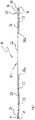
- Figure 1 shows a side view of a first embodiment of a yieldable rock anchor, or rock bolt, generally designated at 10.
- the rock anchor 10 includes an elongated tendon 12 extending longitudinally along a tendon axis A from a proximal end 16 to a distal end 18.
- the tendon 12 is preferably fabricated from metal, such as a steel bar, however other bar constructions are possible. While the tendon 12 will usually have an at least essentially circular cross section, the present invention is not limited to tendons having a circular cross section.
- the tendon 12 has a substantially non-yielding rigid first anchor portion 20 intended to firmly anchor the tendon in place.
- the first anchor portion 20 is made from a hollow bar member and is provided, on an outer surface thereof, with a plurality of anchoring members 22 which in the embodiment shown take the form of ribs, such as on a conventional rebar, but may also take the form of grooves, slots, indentations, threads, bosses and studs.
- the anchoring members 22 are provided to enhance a fixing action between the first anchor portion, a bonding agent such as grout or resin, and the surrounding rock structure. As is well-known to skilled persons in the field to which the present invention pertains, grout or resin is used to fasten a rock anchor in a borehole.
- the rock anchor 10 is of the self-drilling variety, and to this end includes a drilling head 24 mounted to the distal end 18 of the tendon 12.
- a plastically deformable axially yielding portion 26 which is also made from a hollow bar member but has a generally smooth outer surface.
- both the hollow rigid first anchor portion 20 and the hollow yielding portion 26 are made of steel and are welded to one another at weld 28a to thus form at least a part of the elongated tendon 12.
- the hollow rigid first anchor portion 20 and the hollow yielding portion 26 may be glued to one another.
- the yielding portion 26 has essentially the same outer diameter as the first anchor portion 20, but it is also possible for the yielding portion to have an outer diameter that is smaller than the outer diameter of the rigid anchor portion 20.
- a proximal externally threaded end portion 30 includes the proximal end 16 and is joined, either integrally or by welding as shown at 28b, to the yielding portion 26.
- the proximal end 16 projects outwardly beyond a rock face and is configured, by way of the externally threaded portion 30, to cooperate with an anchor plate 32 and a threadingly engagable nut 34 used to clamp the proximal end of the rock anchor 10 against the rock face and to apply a suitable pretension, if desired.
- the externally threaded portion 30 of the tendon 12 may in use act as a substantially non-yielding rigid further anchor portion 36 to the extent it is located within a borehole (not shown), that is in an area extending approximately from the anchor plate 32 towards the distal end 18.
- the yieldable rock anchor 10 shown in figure 1 includes the at least substantially non-yielding first anchor portion 20 closest to the toe of the borehole, i.e. closest to the distal end 18 of the tendon 12, as well as the plastically deformable axially yielding portion 26 located intermediate the first anchor portion 20 and the proximal end 16, and an at least substantially non-yielding rigid further anchor portion 36 located intermediate the proximal end 16 and the yielding portion 26.
- both the first anchor portion 20 and the further anchor portion 36 In order for the rock anchor 10 to operate as intended, both the first anchor portion 20 and the further anchor portion 36, regardless of the material used to make them, must have a strength which is sufficiently higher than a strength of the yielding portion 26 to ensure that it is the plastically deformable yielding portion 26 which lengthens or elongates axially with dilating rock, to thereby accommodate and absorb the rock forces without having the rock anchor 10 fail.
- strength tolerance bands of the first anchor portion and any further anchor portion as well as of the at least one yielding portion, it is important to ascertain that the tolerance bands of the anchor portions and the yielding portion(s) do not overlap.
- the yielding portion 26 forms a debonded section whereas the first anchor portion and any further anchor portion forms a bonded section, i.e. bonded to the surrounding rock structure.
- the yielding portion 26 has a generally smooth outer surface, thus facilitating debonding.
- the outer surface of the yielding portion 26, or any yielding portion may be suitably coated to reduce friction, for example by applying a thin layer of oil or another non-stick material.
- anchoring members 22 in the form of ribs or threads are provided on anchor portions 20, 36, they may be formed onto the outer surface of the respective anchor portion by using a cold rolling process (or any other suitable press forming operation), by which the strength of the hollow bar member forming an anchor portion is increased and its plasticity reduced when compared to a hollow bar member which consists of the same type of steel and has not been subjected to a cold rolling process.
- hollow bar members intended to form yielding portions may be heat-treated, thus increasing their capability to plastically deform by decreasing strength.
- yieldable rock anchors 10 according to the present invention were found to allow elongations of between 120 mm/m and 150 mm/m, corresponding to an axial deformation of between 12% and 15%, respectively. This is considered a huge improvement over prior art yieldable rock anchors which allow axial deformations in the range of approximately 0.3% to 2%.
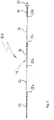
- Figure 2 shows a side view of a second embodiment of a yieldable rock anchor 10b according to the present invention, which is similar to the first embodiment shown in figure 1 , but includes, in addition to the substantially non-yielding rigid first anchor portion 20, a plurality of substantially non-yielding rigid further anchor portions 36 as well as a plurality of plastically deformable axially yielding portions 26 in alternating arrangement.
- two non-yielding further anchor portions 36 and two axially yielding portions 26 are shown, but any number of such further anchor portions and axially yielding portions is contemplated.
- the anchor portions and axially yielding portions of figure 2 are welded (or glued) to one another at welds 28a - 28d.
- an axially yielding portion 26 may have a length of one meter, but may also be shorter or longer. Also, the length and/or diameter of both the anchor portions and the yielding portions forming the tendon 12 may vary, that is, each anchor portion and each the yielding portion need not have the same length and/or diameter.
Landscapes
- Engineering & Computer Science (AREA)
- Mining & Mineral Resources (AREA)
- Structural Engineering (AREA)
- Life Sciences & Earth Sciences (AREA)
- General Life Sciences & Earth Sciences (AREA)
- Geochemistry & Mineralogy (AREA)
- Geology (AREA)
- Piles And Underground Anchors (AREA)
- Devices Affording Protection Of Roads Or Walls For Sound Insulation (AREA)
Claims (12)
- Nachgiebiger Felsanker (10), mit:- einem nicht einheitlichen, länglichen Spannglied (12), das sich in Längsrichtung entlang einer Spanngliedachse (A) von einem proximalen Ende (16) zu einem distalen Ende (18) erstreckt, wobei das Spannglied umfasst-- einen im Wesentlichen unnachgiebigen, starren ersten Verankerungsabschnitt (20), und-- mindestens einen plastisch verformbaren, axial nachgiebigen Abschnitt (26) zwischen dem unnachgiebigen, starren ersten Verankerungsabschnitt (20) und dem proximalen Ende (16),wobei sowohl der erste Verankerungsabschnitt (20) als auch der mindestens eine nachgiebige Abschnitt (26) hohle Stabelemente sind,
dadurch gekennzeichnet, dass- der erste Verankerungsabschnitt (20) an dem distalen Ende (18) angeordnet ist und sich zu dem proximalen Ende (16) hin erstreckt,- der erste Verankerungsabschnitt (20) und der mindestens eine nachgiebige Abschnitt (26) einstückig miteinander durch Schweißen oder Kleben verbunden sind, um mindestens einen Teil des länglichen Spannglieds (12) zu bilden,- Festigkeitstoleranzbänder eines im Wesentlichen unnachgiebigen starren Verankerungsabschnitts (20, 36) und des mindestens einen plastisch verformbaren, axial nachgiebigen Abschnitts (26) sich nicht überlappen, und- der mindestens eine axial nachgiebige Abschnitt (26) einen Verformungsbereich von mindestens 100 mm/m, vorzugsweise von mindestens 120 mm/m und besonders bevorzugt von mindestens 150 mm/m aufweist. - Nachgiebiger Felsanker nach Anspruch 1,
wobei der Felsanker selbstbohrend ist. - Nachgiebiger Felsanker nach einem der vorhergehenden Ansprüche,
wobei das Spannglied (12) mindestens einen im Wesentlichen unnachgiebigen starren weiteren Verankerungsabschnitt (36) zwischen dem proximalen Ende (16) und dem mindestens einen nachgiebigen Abschnitt (26) aufweist. - Nachgiebiger Felsanker nach einem der vorhergehenden Ansprüche,
wobei der unnachgiebige starre erste Verankerungsabschnitt (20) mit mehreren Verankerungselementen (22) versehen ist, die von einer Außenfläche des ersten Verankerungsabschnitts (20) vorstehen. - Nachgiebiger Felsanker nach Anspruch 3 oder 4,
wobei das Spannglied (12) mehrere im Wesentlichen unnachgiebige, starre weitere Verankerungsabschnitten (36) und mehrere plastisch verformbare, axial nachgiebige Abschnitten (26) in alternierender Anordnung aufweist. - Nachgiebiger Felsanker nach einem der Ansprüche 3 bis 5,
wobei der mindestens eine oder jeder im Wesentlichen unnachgiebige starre weitere Verankerungsabschnitt (36) mit mehreren Verankerungselementen (22) versehen ist, die von einer Außenfläche des jeweiligen weiteren Verankerungsabschnitts (36) vorstehen. - Nachgiebiger Felsanker nach einem der Ansprüche 4 bis 6,
wobei die mehreren Verankerungselemente (22) Vorsprünge aufweisen, die aus der Gruppe von Rippen, Nuten, Schlitzen, Vertiefungen, Gewinden, Vorsprüngen und Bolzen ausgewählt sind. - Nachgiebiger Felsanker nach einem der vorhergehenden Ansprüche,
wobei jeder nachgiebige Abschnitt (26) eine allgemein glatte Außenfläche aufweist. - Nachgiebiger Felsanker nach einem der vorhergehenden Ansprüche,
wobei der mindestens eine oder mindestens ein nachgiebiger Abschnitt (26) einen Außendurchmesser hat, der kleiner ist als der Außendurchmesser eines benachbarten starren Verankerungsabschnitts. - Nachgiebiger Felsanker nach einem der vorhergehenden Ansprüche,
wobei der erste Verankerungsabschnitt (20) und jeder weitere Verankerungsabschnitt (36) eine höhere Festigkeit aufweist als der mindestens eine nachgiebige Abschnitt (26). - Nachgiebiger Felsanker nach einem der vorhergehenden Ansprüche,
wobei der mindestens eine nachgiebige Abschnitt (26), der erste Verankerungsabschnitt (20) und jeder weitere Verankerungsabschnitt (36) Stahlhohlstabglieder sind, wobei sich der Stahl der Hohlstabglieder, die den mindestens einen nachgiebigen Abschnitt (26) bilden, von dem Stahl der Hohlstabglieder unterscheidet, die den ersten Verankerungsabschnitt (20) und jeden weiteren Verankerungsabschnitt (36) bilden. - Nachgiebiger Felsanker nach einem der vorhergehenden Ansprüche,
wobei das Spannglied (12) einen Außengewindeabschnitt (30) am oder in der Nähe des proximalen Endes aufweist.
Priority Applications (2)
| Application Number | Priority Date | Filing Date | Title |
|---|---|---|---|
| RS20221015A RS63711B1 (sr) | 2017-01-09 | 2017-01-09 | Kompozitni produživi anker za stene sa poboljšanim opsegom deformacija |
| PL17700209.4T PL3565954T3 (pl) | 2017-01-09 | 2017-01-09 | Kompozytowa podatna kotwa skalna z ulepszonym zakresem odkształcenia |
Applications Claiming Priority (1)
| Application Number | Priority Date | Filing Date | Title |
|---|---|---|---|
| PCT/EP2017/050331 WO2018127294A1 (en) | 2017-01-09 | 2017-01-09 | Composite yieldable rock anchor with improved deformation range |
Publications (3)
| Publication Number | Publication Date |
|---|---|
| EP3565954A1 EP3565954A1 (de) | 2019-11-13 |
| EP3565954B1 true EP3565954B1 (de) | 2022-09-28 |
| EP3565954B8 EP3565954B8 (de) | 2022-11-02 |
Family
ID=57777637
Family Applications (1)
| Application Number | Title | Priority Date | Filing Date |
|---|---|---|---|
| EP17700209.4A Active EP3565954B8 (de) | 2017-01-09 | 2017-01-09 | Zusammengesetzter nachgiebiger felsanker mit verbessertem deformationsbereich |
Country Status (11)
| Country | Link |
|---|---|
| US (1) | US10697297B2 (de) |
| EP (1) | EP3565954B8 (de) |
| AU (1) | AU2017390346B2 (de) |
| CA (1) | CA3049061C (de) |
| ES (1) | ES2929633T3 (de) |
| PL (1) | PL3565954T3 (de) |
| PT (1) | PT3565954T (de) |
| RS (1) | RS63711B1 (de) |
| RU (1) | RU2724176C1 (de) |
| WO (1) | WO2018127294A1 (de) |
| ZA (1) | ZA201904351B (de) |
Families Citing this family (8)
| Publication number | Priority date | Publication date | Assignee | Title |
|---|---|---|---|---|
| US10941657B2 (en) * | 2016-07-12 | 2021-03-09 | Fci Holdings Delaware, Inc. | Corrosion resistant yieldable bolt |
| PE20210265A1 (es) * | 2018-05-11 | 2021-02-10 | Epiroc Drilling Tools Ab | Metodo para garantizar el fallo controlado de barra de perno para roca |
| CN109681253A (zh) * | 2019-02-27 | 2019-04-26 | 太原理工大学 | 一种井下深部围岩支护新型锚杆 |
| CA3160321A1 (en) * | 2019-11-06 | 2021-05-14 | David William Evans | Rock bolt |
| CN112664249B (zh) * | 2020-11-30 | 2022-02-01 | 绍兴文理学院 | 一种让压长度可调的多级承载大变形锚杆 |
| CN112878323A (zh) * | 2021-01-08 | 2021-06-01 | 中国水利水电科学研究院 | 一种可装配式预应力锚索结构 |
| US20220380997A1 (en) * | 2021-05-28 | 2022-12-01 | Carrick Pierce | Soil nail/micropile comprising dissimilar bars connected with transition coupler |
| RU207877U1 (ru) * | 2021-07-26 | 2021-11-22 | Виталий Юрьевич Лузин | Фрикционный гидрораспорный трубчатый анкер |
Citations (3)
| Publication number | Priority date | Publication date | Assignee | Title |
|---|---|---|---|---|
| WO2008079021A1 (en) * | 2006-12-22 | 2008-07-03 | Dynamic Rock Support As | A deformable rock bolt |
| US20160326873A1 (en) * | 2015-05-08 | 2016-11-10 | Normet International, Ltd. | Locally Anchored Self-Drilling Hollow Rock Bolt |
| WO2018013528A2 (en) * | 2016-07-12 | 2018-01-18 | Fci Holdings Delaware, Inc. | Corrosion resistant yieldable bolt |
Family Cites Families (18)
| Publication number | Priority date | Publication date | Assignee | Title |
|---|---|---|---|---|
| DE2941769C2 (de) * | 1979-10-16 | 1985-10-31 | Upat Gmbh & Co, 7830 Emmendingen | Verfahren zum Setzen eines Ankerbolzens und Ankerbolzen |
| US4295761A (en) * | 1979-12-10 | 1981-10-20 | Stratabolt Corporation | Post tensionable grouted anchor assembly |
| WO1994007619A1 (en) * | 1992-09-25 | 1994-04-14 | Bhp Engineering Pty. Ltd. | Hollow bars and method of manufacture |
| US5483781A (en) * | 1994-06-13 | 1996-01-16 | Illinois Tool Works Inc. | Construction fastener assembly |
| ES2116202B1 (es) * | 1995-11-03 | 1999-03-01 | Tierra Armada S A | Nuevas armaduras y sistema de refuerzo para tierra estabilizada. |
| US5873689A (en) * | 1997-07-03 | 1999-02-23 | Milad Mansour | Low torque threaded fastener and mine roof support system using such a fastener |
| DE19955684A1 (de) * | 1999-11-19 | 2001-05-23 | Hilti Ag | Ankerstange für Verankerungen mit organischen und/oder anorganischen Mörtelmassen |
| US20070269274A1 (en) * | 2003-06-03 | 2007-11-22 | Ross Seedsman | Rock Bolt |
| WO2007053893A1 (en) * | 2005-11-09 | 2007-05-18 | Sandvik Intellectual Property Ab | Self drilling rock bolt |
| AU2007203409B2 (en) * | 2006-07-20 | 2009-10-22 | Fci Holdings Delaware, Inc. | Rock bolt |
| US20080148595A1 (en) | 2006-12-20 | 2008-06-26 | Lam Research Corporation | Method and apparatus for drying substrates using a surface tensions reducing gas |
| AU2008202980A1 (en) | 2007-07-04 | 2009-01-22 | Fero Group Pty Ltd | Yielding rock bolt |
| AU2007214343B2 (en) * | 2007-08-31 | 2009-08-13 | Sandvik Intellectual Property Ab | Rock bolt with mechanical anchor |
| AU2008221612B2 (en) * | 2007-09-24 | 2009-05-14 | Sandvik Intellectual Property Ab | Rock Bolt |
| RU2448253C1 (ru) * | 2008-02-29 | 2012-04-20 | Атлас Копко Май Гмбх | Усовершенствованный скользящий анкер |
| US8790044B2 (en) * | 2009-08-05 | 2014-07-29 | F. M. Locotos Co., Inc. | Tensionable tubular resin anchored tubular bolt and method |
| WO2011075810A1 (en) | 2009-12-22 | 2011-06-30 | Mansour Mining Inc. | Anchor tendon with selectively deformable portions |
| CA2917978C (en) * | 2013-07-12 | 2019-06-11 | Minova International Limited | Yieldable rock anchor |
-
2017
- 2017-01-09 WO PCT/EP2017/050331 patent/WO2018127294A1/en not_active Ceased
- 2017-01-09 PT PT177002094T patent/PT3565954T/pt unknown
- 2017-01-09 PL PL17700209.4T patent/PL3565954T3/pl unknown
- 2017-01-09 CA CA3049061A patent/CA3049061C/en active Active
- 2017-01-09 EP EP17700209.4A patent/EP3565954B8/de active Active
- 2017-01-09 AU AU2017390346A patent/AU2017390346B2/en active Active
- 2017-01-09 RU RU2019124334A patent/RU2724176C1/ru active
- 2017-01-09 RS RS20221015A patent/RS63711B1/sr unknown
- 2017-01-09 US US16/476,697 patent/US10697297B2/en active Active
- 2017-01-09 ES ES17700209T patent/ES2929633T3/es active Active
-
2019
- 2019-07-02 ZA ZA2019/04351A patent/ZA201904351B/en unknown
Patent Citations (3)
| Publication number | Priority date | Publication date | Assignee | Title |
|---|---|---|---|---|
| WO2008079021A1 (en) * | 2006-12-22 | 2008-07-03 | Dynamic Rock Support As | A deformable rock bolt |
| US20160326873A1 (en) * | 2015-05-08 | 2016-11-10 | Normet International, Ltd. | Locally Anchored Self-Drilling Hollow Rock Bolt |
| WO2018013528A2 (en) * | 2016-07-12 | 2018-01-18 | Fci Holdings Delaware, Inc. | Corrosion resistant yieldable bolt |
Also Published As
| Publication number | Publication date |
|---|---|
| AU2017390346A1 (en) | 2019-07-18 |
| RS63711B1 (sr) | 2022-11-30 |
| WO2018127294A1 (en) | 2018-07-12 |
| RU2724176C1 (ru) | 2020-06-22 |
| PL3565954T3 (pl) | 2022-12-12 |
| ZA201904351B (en) | 2023-03-29 |
| EP3565954B8 (de) | 2022-11-02 |
| EP3565954A1 (de) | 2019-11-13 |
| ES2929633T3 (es) | 2022-11-30 |
| US20190376388A1 (en) | 2019-12-12 |
| US10697297B2 (en) | 2020-06-30 |
| PT3565954T (pt) | 2022-11-09 |
| AU2017390346B2 (en) | 2022-11-17 |
| CA3049061A1 (en) | 2018-07-12 |
| CA3049061C (en) | 2021-01-26 |
Similar Documents
| Publication | Publication Date | Title |
|---|---|---|
| EP3565954B1 (de) | Zusammengesetzter nachgiebiger felsanker mit verbessertem deformationsbereich | |
| CA2985032C (en) | Locally anchored self-drilling hollow rock bolt | |
| KR101142635B1 (ko) | 변형 가능한 암석 볼트 | |
| EP2683953B1 (de) | Anker-befestigungselement | |
| RU2458226C2 (ru) | Пустотелый анкерный болт, самозабуривающийся анкерный болт и способ формования пустотелого анкерного болта | |
| US8899883B2 (en) | Anchor tendon with selectively deformable portions | |
| US6592286B2 (en) | Fixing member for use with a setting material | |
| AU2020381020A1 (en) | Rock bolt | |
| AU2021218166A1 (en) | Rock bolt | |
| CZ11593U1 (cs) | Stavební kotva |
Legal Events
| Date | Code | Title | Description |
|---|---|---|---|
| STAA | Information on the status of an ep patent application or granted ep patent |
Free format text: STATUS: UNKNOWN |
|
| STAA | Information on the status of an ep patent application or granted ep patent |
Free format text: STATUS: THE INTERNATIONAL PUBLICATION HAS BEEN MADE |
|
| PUAI | Public reference made under article 153(3) epc to a published international application that has entered the european phase |
Free format text: ORIGINAL CODE: 0009012 |
|
| STAA | Information on the status of an ep patent application or granted ep patent |
Free format text: STATUS: REQUEST FOR EXAMINATION WAS MADE |
|
| 17P | Request for examination filed |
Effective date: 20190801 |
|
| AK | Designated contracting states |
Kind code of ref document: A1 Designated state(s): AL AT BE BG CH CY CZ DE DK EE ES FI FR GB GR HR HU IE IS IT LI LT LU LV MC MK MT NL NO PL PT RO RS SE SI SK SM TR |
|
| AX | Request for extension of the european patent |
Extension state: BA ME |
|
| DAV | Request for validation of the european patent (deleted) | ||
| DAX | Request for extension of the european patent (deleted) | ||
| STAA | Information on the status of an ep patent application or granted ep patent |
Free format text: STATUS: EXAMINATION IS IN PROGRESS |
|
| 17Q | First examination report despatched |
Effective date: 20201027 |
|
| GRAP | Despatch of communication of intention to grant a patent |
Free format text: ORIGINAL CODE: EPIDOSNIGR1 |
|
| STAA | Information on the status of an ep patent application or granted ep patent |
Free format text: STATUS: GRANT OF PATENT IS INTENDED |
|
| INTG | Intention to grant announced |
Effective date: 20220519 |
|
| GRAS | Grant fee paid |
Free format text: ORIGINAL CODE: EPIDOSNIGR3 |
|
| GRAA | (expected) grant |
Free format text: ORIGINAL CODE: 0009210 |
|
| STAA | Information on the status of an ep patent application or granted ep patent |
Free format text: STATUS: THE PATENT HAS BEEN GRANTED |
|
| REG | Reference to a national code |
Ref country code: DE Ref legal event code: R081 Ref document number: 602017062111 Country of ref document: DE Owner name: MINOVA INTERNATIONAL LIMITED, GB Free format text: FORMER OWNER: MINOVA INTERNATIONAL LIMITED, BARNSLEY, SOUTH YORKSHIRE, GB |
|
| AK | Designated contracting states |
Kind code of ref document: B1 Designated state(s): AL AT BE BG CH CY CZ DE DK EE ES FI FR GB GR HR HU IE IS IT LI LT LU LV MC MK MT NL NO PL PT RO RS SE SI SK SM TR |
|
| REG | Reference to a national code |
Ref country code: GB Ref legal event code: FG4D |
|
| REG | Reference to a national code |
Ref country code: CH Ref legal event code: EP |
|
| RAP4 | Party data changed (patent owner data changed or rights of a patent transferred) |
Owner name: MINOVA INTERNATIONAL LIMITED |
|
| REG | Reference to a national code |
Ref country code: CH Ref legal event code: PK Free format text: BERICHTIGUNG B8 |
|
| REG | Reference to a national code |
Ref country code: AT Ref legal event code: REF Ref document number: 1521352 Country of ref document: AT Kind code of ref document: T Effective date: 20221015 |
|
| REG | Reference to a national code |
Ref country code: DE Ref legal event code: R096 Ref document number: 602017062111 Country of ref document: DE |
|
| REG | Reference to a national code |
Ref country code: IE Ref legal event code: FG4D |
|
| REG | Reference to a national code |
Ref country code: PT Ref legal event code: SC4A Ref document number: 3565954 Country of ref document: PT Date of ref document: 20221109 Kind code of ref document: T Free format text: AVAILABILITY OF NATIONAL TRANSLATION Effective date: 20221104 |
|
| REG | Reference to a national code |
Ref country code: SE Ref legal event code: TRGR |
|
| REG | Reference to a national code |
Ref country code: ES Ref legal event code: FG2A Ref document number: 2929633 Country of ref document: ES Kind code of ref document: T3 Effective date: 20221130 |
|
| REG | Reference to a national code |
Ref country code: NO Ref legal event code: T2 Effective date: 20220928 |
|
| REG | Reference to a national code |
Ref country code: LT Ref legal event code: MG9D |
|
| PG25 | Lapsed in a contracting state [announced via postgrant information from national office to epo] |
Ref country code: LV Free format text: LAPSE BECAUSE OF FAILURE TO SUBMIT A TRANSLATION OF THE DESCRIPTION OR TO PAY THE FEE WITHIN THE PRESCRIBED TIME-LIMIT Effective date: 20220928 Ref country code: LT Free format text: LAPSE BECAUSE OF FAILURE TO SUBMIT A TRANSLATION OF THE DESCRIPTION OR TO PAY THE FEE WITHIN THE PRESCRIBED TIME-LIMIT Effective date: 20220928 |
|
| REG | Reference to a national code |
Ref country code: NL Ref legal event code: MP Effective date: 20220928 |
|
| REG | Reference to a national code |
Ref country code: AT Ref legal event code: MK05 Ref document number: 1521352 Country of ref document: AT Kind code of ref document: T Effective date: 20220928 |
|
| PG25 | Lapsed in a contracting state [announced via postgrant information from national office to epo] |
Ref country code: HR Free format text: LAPSE BECAUSE OF FAILURE TO SUBMIT A TRANSLATION OF THE DESCRIPTION OR TO PAY THE FEE WITHIN THE PRESCRIBED TIME-LIMIT Effective date: 20220928 Ref country code: GR Free format text: LAPSE BECAUSE OF FAILURE TO SUBMIT A TRANSLATION OF THE DESCRIPTION OR TO PAY THE FEE WITHIN THE PRESCRIBED TIME-LIMIT Effective date: 20221229 |
|
| PG25 | Lapsed in a contracting state [announced via postgrant information from national office to epo] |
Ref country code: SM Free format text: LAPSE BECAUSE OF FAILURE TO SUBMIT A TRANSLATION OF THE DESCRIPTION OR TO PAY THE FEE WITHIN THE PRESCRIBED TIME-LIMIT Effective date: 20220928 Ref country code: RO Free format text: LAPSE BECAUSE OF FAILURE TO SUBMIT A TRANSLATION OF THE DESCRIPTION OR TO PAY THE FEE WITHIN THE PRESCRIBED TIME-LIMIT Effective date: 20220928 Ref country code: CZ Free format text: LAPSE BECAUSE OF FAILURE TO SUBMIT A TRANSLATION OF THE DESCRIPTION OR TO PAY THE FEE WITHIN THE PRESCRIBED TIME-LIMIT Effective date: 20220928 Ref country code: AT Free format text: LAPSE BECAUSE OF FAILURE TO SUBMIT A TRANSLATION OF THE DESCRIPTION OR TO PAY THE FEE WITHIN THE PRESCRIBED TIME-LIMIT Effective date: 20220928 |
|
| PG25 | Lapsed in a contracting state [announced via postgrant information from national office to epo] |
Ref country code: SK Free format text: LAPSE BECAUSE OF FAILURE TO SUBMIT A TRANSLATION OF THE DESCRIPTION OR TO PAY THE FEE WITHIN THE PRESCRIBED TIME-LIMIT Effective date: 20220928 Ref country code: IS Free format text: LAPSE BECAUSE OF FAILURE TO SUBMIT A TRANSLATION OF THE DESCRIPTION OR TO PAY THE FEE WITHIN THE PRESCRIBED TIME-LIMIT Effective date: 20230128 Ref country code: EE Free format text: LAPSE BECAUSE OF FAILURE TO SUBMIT A TRANSLATION OF THE DESCRIPTION OR TO PAY THE FEE WITHIN THE PRESCRIBED TIME-LIMIT Effective date: 20220928 |
|
| REG | Reference to a national code |
Ref country code: DE Ref legal event code: R097 Ref document number: 602017062111 Country of ref document: DE |
|
| PG25 | Lapsed in a contracting state [announced via postgrant information from national office to epo] |
Ref country code: NL Free format text: LAPSE BECAUSE OF FAILURE TO SUBMIT A TRANSLATION OF THE DESCRIPTION OR TO PAY THE FEE WITHIN THE PRESCRIBED TIME-LIMIT Effective date: 20220928 Ref country code: AL Free format text: LAPSE BECAUSE OF FAILURE TO SUBMIT A TRANSLATION OF THE DESCRIPTION OR TO PAY THE FEE WITHIN THE PRESCRIBED TIME-LIMIT Effective date: 20220928 |
|
| PG25 | Lapsed in a contracting state [announced via postgrant information from national office to epo] |
Ref country code: DK Free format text: LAPSE BECAUSE OF FAILURE TO SUBMIT A TRANSLATION OF THE DESCRIPTION OR TO PAY THE FEE WITHIN THE PRESCRIBED TIME-LIMIT Effective date: 20220928 |
|
| REG | Reference to a national code |
Ref country code: DE Ref legal event code: R119 Ref document number: 602017062111 Country of ref document: DE |
|
| PLBE | No opposition filed within time limit |
Free format text: ORIGINAL CODE: 0009261 |
|
| STAA | Information on the status of an ep patent application or granted ep patent |
Free format text: STATUS: NO OPPOSITION FILED WITHIN TIME LIMIT |
|
| REG | Reference to a national code |
Ref country code: CH Ref legal event code: PL |
|
| 26N | No opposition filed |
Effective date: 20230629 |
|
| GBPC | Gb: european patent ceased through non-payment of renewal fee |
Effective date: 20230109 |
|
| PG25 | Lapsed in a contracting state [announced via postgrant information from national office to epo] |
Ref country code: LU Free format text: LAPSE BECAUSE OF NON-PAYMENT OF DUE FEES Effective date: 20230109 |
|
| REG | Reference to a national code |
Ref country code: BE Ref legal event code: MM Effective date: 20230131 |
|
| PG25 | Lapsed in a contracting state [announced via postgrant information from national office to epo] |
Ref country code: LI Free format text: LAPSE BECAUSE OF NON-PAYMENT OF DUE FEES Effective date: 20230131 Ref country code: GB Free format text: LAPSE BECAUSE OF NON-PAYMENT OF DUE FEES Effective date: 20230109 Ref country code: DE Free format text: LAPSE BECAUSE OF NON-PAYMENT OF DUE FEES Effective date: 20230801 Ref country code: CH Free format text: LAPSE BECAUSE OF NON-PAYMENT OF DUE FEES Effective date: 20230131 |
|
| PG25 | Lapsed in a contracting state [announced via postgrant information from national office to epo] |
Ref country code: SI Free format text: LAPSE BECAUSE OF FAILURE TO SUBMIT A TRANSLATION OF THE DESCRIPTION OR TO PAY THE FEE WITHIN THE PRESCRIBED TIME-LIMIT Effective date: 20220928 Ref country code: FR Free format text: LAPSE BECAUSE OF NON-PAYMENT OF DUE FEES Effective date: 20230131 Ref country code: BE Free format text: LAPSE BECAUSE OF NON-PAYMENT OF DUE FEES Effective date: 20230131 |
|
| PG25 | Lapsed in a contracting state [announced via postgrant information from national office to epo] |
Ref country code: IE Free format text: LAPSE BECAUSE OF NON-PAYMENT OF DUE FEES Effective date: 20230109 |
|
| PG25 | Lapsed in a contracting state [announced via postgrant information from national office to epo] |
Ref country code: IT Free format text: LAPSE BECAUSE OF FAILURE TO SUBMIT A TRANSLATION OF THE DESCRIPTION OR TO PAY THE FEE WITHIN THE PRESCRIBED TIME-LIMIT Effective date: 20220928 |
|
| PG25 | Lapsed in a contracting state [announced via postgrant information from national office to epo] |
Ref country code: MC Free format text: LAPSE BECAUSE OF FAILURE TO SUBMIT A TRANSLATION OF THE DESCRIPTION OR TO PAY THE FEE WITHIN THE PRESCRIBED TIME-LIMIT Effective date: 20220928 |
|
| PG25 | Lapsed in a contracting state [announced via postgrant information from national office to epo] |
Ref country code: MC Free format text: LAPSE BECAUSE OF FAILURE TO SUBMIT A TRANSLATION OF THE DESCRIPTION OR TO PAY THE FEE WITHIN THE PRESCRIBED TIME-LIMIT Effective date: 20220928 |
|
| PG25 | Lapsed in a contracting state [announced via postgrant information from national office to epo] |
Ref country code: BG Free format text: LAPSE BECAUSE OF FAILURE TO SUBMIT A TRANSLATION OF THE DESCRIPTION OR TO PAY THE FEE WITHIN THE PRESCRIBED TIME-LIMIT Effective date: 20220928 |
|
| PG25 | Lapsed in a contracting state [announced via postgrant information from national office to epo] |
Ref country code: BG Free format text: LAPSE BECAUSE OF FAILURE TO SUBMIT A TRANSLATION OF THE DESCRIPTION OR TO PAY THE FEE WITHIN THE PRESCRIBED TIME-LIMIT Effective date: 20220928 |
|
| PGFP | Annual fee paid to national office [announced via postgrant information from national office to epo] |
Ref country code: PT Payment date: 20241230 Year of fee payment: 9 |
|
| PGFP | Annual fee paid to national office [announced via postgrant information from national office to epo] |
Ref country code: FI Payment date: 20250121 Year of fee payment: 9 |
|
| PGFP | Annual fee paid to national office [announced via postgrant information from national office to epo] |
Ref country code: ES Payment date: 20250214 Year of fee payment: 9 |
|
| PGFP | Annual fee paid to national office [announced via postgrant information from national office to epo] |
Ref country code: SE Payment date: 20250122 Year of fee payment: 9 |
|
| PGFP | Annual fee paid to national office [announced via postgrant information from national office to epo] |
Ref country code: NO Payment date: 20250121 Year of fee payment: 9 |
|
| PGFP | Annual fee paid to national office [announced via postgrant information from national office to epo] |
Ref country code: PL Payment date: 20250102 Year of fee payment: 9 |
|
| PG25 | Lapsed in a contracting state [announced via postgrant information from national office to epo] |
Ref country code: CY Free format text: LAPSE BECAUSE OF FAILURE TO SUBMIT A TRANSLATION OF THE DESCRIPTION OR TO PAY THE FEE WITHIN THE PRESCRIBED TIME-LIMIT; INVALID AB INITIO Effective date: 20170109 |
|
| PG25 | Lapsed in a contracting state [announced via postgrant information from national office to epo] |
Ref country code: HU Free format text: LAPSE BECAUSE OF FAILURE TO SUBMIT A TRANSLATION OF THE DESCRIPTION OR TO PAY THE FEE WITHIN THE PRESCRIBED TIME-LIMIT; INVALID AB INITIO Effective date: 20170109 |
|
| PG25 | Lapsed in a contracting state [announced via postgrant information from national office to epo] |
Ref country code: TR Free format text: LAPSE BECAUSE OF FAILURE TO SUBMIT A TRANSLATION OF THE DESCRIPTION OR TO PAY THE FEE WITHIN THE PRESCRIBED TIME-LIMIT Effective date: 20220928 |
|
| PGFP | Annual fee paid to national office [announced via postgrant information from national office to epo] |
Ref country code: RS Payment date: 20251230 Year of fee payment: 10 |