EP3565968B1 - Verfahren und abdeckung zur abdeckung einer öffnung in einem bauteil einer windturbine - Google Patents
Verfahren und abdeckung zur abdeckung einer öffnung in einem bauteil einer windturbine Download PDFInfo
- Publication number
- EP3565968B1 EP3565968B1 EP17823038.9A EP17823038A EP3565968B1 EP 3565968 B1 EP3565968 B1 EP 3565968B1 EP 17823038 A EP17823038 A EP 17823038A EP 3565968 B1 EP3565968 B1 EP 3565968B1
- Authority
- EP
- European Patent Office
- Prior art keywords
- cover
- torus
- component
- opening
- tarpaulin
- Prior art date
- Legal status (The legal status is an assumption and is not a legal conclusion. Google has not performed a legal analysis and makes no representation as to the accuracy of the status listed.)
- Active
Links
Images


Classifications
-
- F—MECHANICAL ENGINEERING; LIGHTING; HEATING; WEAPONS; BLASTING
- F03—MACHINES OR ENGINES FOR LIQUIDS; WIND, SPRING, OR WEIGHT MOTORS; PRODUCING MECHANICAL POWER OR A REACTIVE PROPULSIVE THRUST, NOT OTHERWISE PROVIDED FOR
- F03D—WIND MOTORS
- F03D13/00—Assembly, mounting or commissioning of wind motors; Arrangements specially adapted for transporting wind motor components
- F03D13/10—Assembly of wind motors; Arrangements for erecting wind motors
-
- F—MECHANICAL ENGINEERING; LIGHTING; HEATING; WEAPONS; BLASTING
- F03—MACHINES OR ENGINES FOR LIQUIDS; WIND, SPRING, OR WEIGHT MOTORS; PRODUCING MECHANICAL POWER OR A REACTIVE PROPULSIVE THRUST, NOT OTHERWISE PROVIDED FOR
- F03D—WIND MOTORS
- F03D13/00—Assembly, mounting or commissioning of wind motors; Arrangements specially adapted for transporting wind motor components
- F03D13/40—Arrangements or methods specially adapted for transporting wind motor components
-
- F—MECHANICAL ENGINEERING; LIGHTING; HEATING; WEAPONS; BLASTING
- F03—MACHINES OR ENGINES FOR LIQUIDS; WIND, SPRING, OR WEIGHT MOTORS; PRODUCING MECHANICAL POWER OR A REACTIVE PROPULSIVE THRUST, NOT OTHERWISE PROVIDED FOR
- F03D—WIND MOTORS
- F03D80/00—Details, components or accessories not provided for in groups F03D1/00 - F03D17/00
-
- Y—GENERAL TAGGING OF NEW TECHNOLOGICAL DEVELOPMENTS; GENERAL TAGGING OF CROSS-SECTIONAL TECHNOLOGIES SPANNING OVER SEVERAL SECTIONS OF THE IPC; TECHNICAL SUBJECTS COVERED BY FORMER USPC CROSS-REFERENCE ART COLLECTIONS [XRACs] AND DIGESTS
- Y02—TECHNOLOGIES OR APPLICATIONS FOR MITIGATION OR ADAPTATION AGAINST CLIMATE CHANGE
- Y02E—REDUCTION OF GREENHOUSE GAS [GHG] EMISSIONS, RELATED TO ENERGY GENERATION, TRANSMISSION OR DISTRIBUTION
- Y02E10/00—Energy generation through renewable energy sources
- Y02E10/70—Wind energy
- Y02E10/72—Wind turbines with rotation axis in wind direction
Definitions
- the present invention relates to a method for temporarily covering an opening in a component of a wind turbine. It also relates to a cover and a cover arrangement.
- a simple approach to cover an opening is to place a tarpaulin over it. If the component should be moved while the cover is attached, the tarpaulin needs to be fixed to the component. This can be problematic, since the outside of wind turbine components is often hard to reach once a partial assembly of the wind turbine is achieved.
- the object of the present invention is therefore to provide an improved way to cover openings in wind turbine components during the construction of the wind turbine.
- an inflatable torus as a carrying and support member for the tarpaulin.
- the torus that can be also considered to be a ring
- the torus is inflated, it pushes against the outer circumference of the wall and therefore "grips" the outer circumference of the opening. If the outer circumference of the wall is essentially flat, a frictional connection between the outer circumference of the wall and the torus is achieved.
- components of a wind turbine comprise flanges that are arranged around openings to connect the component to other components of the wind turbine.
- the generator can provide a flange to connected with the rotor hub.
- the torus can engage the flange during the inflation and there will therefore be a form fit between the outer circumference of the wall, especially the flange, and the torus.
- a reliable connection of the tarpaulin with the wall and therefore with the component can be achieved by simply inflating the torus.
- the cover can comprise a valve for inflating the torus, wherein the cover is positioned in such a way that the valve is positioned on the side of the tarpaulin that is facing the opening.
- the valve is arranged within the space that is surrounded by the component and the tarpaulin once the cover is attached.
- the valve is therefore accessible from the inside of the component.
- wind turbines are constructed such that the components are accessible with relative ease from the inside but hard to access from the outside. By placing the valve towards the opening and therefore towards the inside of the component the valve can be easily accessed by a workman during the construction of the wind turbine. It is therefore possible to deflate the torus and therefore disconnect the cover from the component from the inside of the component. After the torus is at least partially deflated the cover becomes flexible and can e. g. be pulled inside the component to remove it.
- the valve can be spaced apart from the torus when the torus is inflated and it can be connected to the torus with at least one inflatable air channel. Especially at least one pair of air channels can be used that from a support rod for the cover when inflated.
- At least one handle can be attached to the tarpaulin, wherein the cover is positioned in such a way that the handle is positioned on the side of the tarpaulin that is facing the opening. This facilitates the removal of the cover from inside the component. To remove the cover the cover can be pulled inside the component by pulling the handle or handles, especially after the torus is deflated.
- the component can be a generator, especially a direct drive generator, a tower section, a wind turbine blade, a nacelle or a hub.
- the method can include a step of demounting the cover from the component, wherein the demounting includes deflating the torus.
- the demounting includes deflating the torus.
- the cover can be pulled inside the component through the opening after deflating the torus. Especially the previously discussed handles can be used to pull the cover through the opening. Since the torus is deflated, the component is flexible and can e. g. be folded to be pulled inside the opening.
- the cover can be demounted from the component after the component is mounted to at least one further component of the wind turbine. It can especially be dismounted after the component is arranged at its final position during the assembly of the wind turbine. In such a final position it is often hard to reach the opening of the component from the outside, since the opening can be placed at large hights. It is however often possible to reach the opening from the inside and remove the cover from the inside as discussed above.
- the invention concerns a cover for covering an opening in a component of a wind turbine, comprising a tarpaulin and an inflatable torus, wherein a circumference of the tarpaulin is attached to the torus such that the tarpaulin extends across the hole of the torus when the torus is inflated.
- a cover for covering an opening in a component of a wind turbine comprising a tarpaulin and an inflatable torus, wherein a circumference of the tarpaulin is attached to the torus such that the tarpaulin extends across the hole of the torus when the torus is inflated.
- the cover can comprise a valve for inflating the torus that is spaced apart from the torus when the torus is inflated and connected to the torus via at least one inflatable air channel.
- the valve can especially be located near the centre of the hole once the torus is inflated. If the cover is attached in such a way that the valve is positioned on the side of the tarpaulin facing the opening of the component the valve can therefore be positioned roughly in the middle of the opening and is therefore easily accessible by a workman to inflate or deflate the torus and the air channel.
- the valve can be connected to the torus via at least one pair of the inflatable air channels, wherein the pair of air channels forms a support rod extending across the hole of the torus when the torus and the air channels are inflated.
- Preferably two support rods can be used that extend roughly orthogonal to each other. If multiple support rods are used they can preferentially cross approximately at the centre of the hole of the torus and/or at the position of the valve. If multiple support rods are used they can be arranged in such a way that the circular hole of the torus is subdivided into roughly equal segments of the circle by the support rods.
- the cover can comprise at least one handle that is attached to the tarpaulin.
- the handle can be lashed to the tarpaulin.
- the handle can preferably be arranged on the same side of the tarpaulin as the valve, especially on the side which is orientated towards the opening of the component.
- the component can be a generator, especially a direct drive generator, a tower section, a wind turbine blade, a nacelle or a hub.
- the invention concerns a cover arrangement, comprising a component of a wind turbine and a cover according to the present invention that is attached to the component.
- the cover arrangement can be produced by the method according to the resent invention.
- the cover arrangement can use a cover comprising at least one handle and/or a valve for inflating the torus and/or one or more air channels connecting the valve to the torus, wherein these components are preferably arranged on the side of the tarpaulin that is facing the opening of the component.
- Fig. 1 shows a cover 1 for covering an opening in a component of a wind turbine.
- the cover 1 comprises an inflatable torus 3 and a tarpaulin 2 that is attached to the torus 3 via its circumference.
- the torus 3 is connected to a valve 4 via inflatable air channels 5.
- the air channels 5 therefore provide additional stability for the cover 1.
- handles 7 are attached to the tarpaulin 2. They can be attached to the tarpaulin 2 by e. g. lashing the handles to the tarpaulin at two points each.
- FIGs 2 and 3 show different views of a cover arrangement 13, in which a cover 1 is used to cover an opening 8 of a component 14 of a wind turbine.
- the component 14 can e. g. be a generator, especially a direct drive generator, a tower section, a wind turbine blade, a nacelle or a hub. Only the section of the component 14 next to the opening 8 is shown in figures 2 and 3 .
- a slightly simplified version of the cover 1 is shown in figures 2 and 3 .
- the cover 1 comprises only one pair of air channels 5, forming a single support rod 6. Only two handles 7 are shown.
- the cover 1 can be easily attached to the component 14 to form the cover arrangement 15 as shown in figures 2 and 3 .
- the cover 1 is first positioned over the opening 8 such that the torus 3 extends around the outer circumference of a wall 9 whose inner circumference delimits the opening 8 and that the tarpaulin 2 extends across the opening 8. While the cover 1 is positioned, the torus 3 and the air channels 5 are in a deflated state. Therefore the connected inner spaces 10, 11 of the torus 3 and the air channels 5 are shrunk down to a smaller size than the size shown in figures 2 and 3 and the cover 1 is quite flexible and can e. g. be folded.
- the torus 3 and the air channels 5 are inflated by pumping e. g. air via the valve into the connected inner spaces 10, 11. Therefore the inner spaces 10, 11 expand and push the torus 3 against the outside of the wall 9 of the opening 8. Since the opening 8 has a flange 15 to connect further components to the opening 8, a form fit between the wall 9 and the torus 3 is formed once the torus is inflated.
- the cover 1 should typically be removed again.
- the component 14 is already in a position where it is quite laborious to access the component 14 from the outside.
- the cover 1 is therefore designed in such a way, that a workman 12 can detach the cover 1 from the inside of the component 14.
- the torus 3 can be deflated via the valve 4. Due to the deflation of the torus 3, the torus 3 can be moved over the flange 15 and the cover 1 can therefore be detached from the opening 8. Deflating the torus 3 also deflates the air channels 5 and therefore softens the support rod or support rods.
- the full cover 1 is flexible again and can be folded to pull it inside the component 14.
- the workman 12 can therefore pull the cover 1 inside the component 14 via the handles 7 after deflating the torus 3.
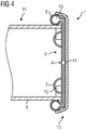
- Fig. 4 shows a slightly different cover arrangement 13 than the cover arrangement shown in figures 2 and 3 . Only the differences between the two cover arrangements 13 will be discussed.
- the component 14 shown in fig. 4 does not comprise outside flanges. In this case the frictional forces exerted by the torus 3 on the wall 9 of the component are sufficiently strong to keep the cover 1 in place. This can be achieved by the right choice of geometry for the torus 3.
- the handles 7 are used as an additional measure to secure the cover 1 to the component 14. As shown schematically in fig. 4 the handles 7 are secured to elements 16 of the component 14. The handles 7 can therefore be used to attach the cover 1 to the component 14 during the inflation and/or deflation of the torus 3 and as an additional security measure to avoid a detachment of the cover 1 from the component 14.
Landscapes
- Engineering & Computer Science (AREA)
- Life Sciences & Earth Sciences (AREA)
- Sustainable Development (AREA)
- Sustainable Energy (AREA)
- Chemical & Material Sciences (AREA)
- Combustion & Propulsion (AREA)
- Mechanical Engineering (AREA)
- General Engineering & Computer Science (AREA)
- Wind Motors (AREA)
Claims (11)
- Verfahren zum vorübergehenden Abdecken einer Öffnung (8) in einem Bestandteil (14) einer Windturbine, das folgende Schritte umfasst:- derartiges Positionieren einer Abdeckung (1), die einen aufblasbaren Ring (3) und eine Plane (2) umfasst, deren Umfang an dem Ring (3) befestigt ist, auf der Öffnung (8), dass der Ring (3) um den Außenumfang einer Wand (9) herum verläuft, deren Innenumfang die Öffnung (8) begrenzt, und dass die Plane (2) über die Öffnung (8) hinweg verläuft, und- Aufblasen des Rings (3) zum Befestigen der Abdeckung (1) an dem Bestandteil (14).
- Verfahren nach Anspruch 1, dadurch gekennzeichnet, dass die Abdeckung (1) ein Ventil (4) zum Aufblasen des Rings (3) umfasst, wobei die Abdeckung (1) so positioniert wird, dass das Ventil (4) auf der der Öffnung (8) zugewandten Seite der Plane (2) positioniert ist.
- Verfahren nach Anspruch 1 oder 2, dadurch gekennzeichnet, dass mindestens ein Griff (7) an der Plane (2) angebracht ist, wobei die Abdeckung (1) so positioniert wird, dass der Griff (7) auf der der Öffnung (8) zugewandten Seite der Plane (2) positioniert ist.
- Verfahren nach einem der vorhergehenden Ansprüche, dadurch gekennzeichnet, dass es sich bei dem Bestandteil (14) um einen Generator, einen Turmabschnitt, ein Windturbinenrotorblatt, eine Gondel oder eine Nabe handelt.
- Verfahren nach einem der vorhergehenden Ansprüche, dadurch gekennzeichnet, dass es ein Abnehmen der Abdeckung (1) von dem Bestandteil (14) umfasst, wobei das Abnehmen das Ablassen von Luft aus dem Ring (3) umfasst.
- Verfahren nach Anspruch 5, wobei die Abdeckung nach dem Ablassen von Luft aus dem Ring (3) über die Öffnung (8) in den Bestandteil (14) hinein gezogen wird.
- Verfahren nach Anspruch 5 oder 6, dadurch gekennzeichnet, dass die Abdeckung (1) von dem Bestandteil (14) abgenommen wird, wenn der Bestandteil an mindestens einem weiteren Bestandteil der Windturbine montiert ist.
- Abdeckung zum Abdecken einer Öffnung (8) in einem Bestandteil (14) einer Windturbine mit einer Plane (2), dadurch gekennzeichnet, dass sie einen aufblasbaren Ring (3) umfasst, wobei ein Umfang der Plane (2) so an dem Ring (3) angebracht ist, dass die Plane (2) über das Loch des Rings (3) hinweg verläuft, wenn dieser aufgeblasen ist, wobei die Abdeckung ein Ventil (4) zum Aufblasen des Rings (3) umfasst, das in einem Abstand zu dem Ring (3) liegt, wenn dieser aufgeblasen ist, und über mindestens einen aufblasbaren Luftkanal (5) mit dem Ring (3) verbunden ist, und
wobei das Ventil (4) über mindestens zwei der aufblasbaren Luftkanäle (5) mit dem Ring (3) verbunden ist,
wobei die zwei Luftkanäle (5) eine Stützstrebe (6) bilden, die über das Loch des Rings (3) hinweg verläuft, wenn der Ring (3) und die Luftkanäle (5) aufgeblasen sind. - Abdeckung nach Anspruch 8, dadurch gekennzeichnet, dass die Abdeckung (1) mindestens einen Griff (7) umfasst, der an der Plane (2) angebracht ist.
- Abdeckung nach einem der Ansprüche 8 und 9, dadurch gekennzeichnet, dass es sich bei dem Bestandteil (14) um einen Generator, einen Turmabschnitt, ein Windturbinenrotorblatt, eine Gondel oder eine Nabe handelt.
- Abdeckungsanordnung, die einen Bestandteil (14) einer Windturbine umfasst, dadurch gekennzeichnet, dass die Abdeckungsanordnung ferner eine Abdeckung (1) nach einem der Ansprüche 8 bis 10 umfasst, die an dem Bestandteil (14) angebracht ist und so eine Öffnung (8) des Bestandteils (14) abdeckt.
Applications Claiming Priority (2)
| Application Number | Priority Date | Filing Date | Title |
|---|---|---|---|
| DE102017202581 | 2017-02-17 | ||
| PCT/EP2017/080612 WO2018149528A1 (en) | 2017-02-17 | 2017-11-28 | Method and cover for covering an opening in a component of a wind turbine |
Publications (2)
| Publication Number | Publication Date |
|---|---|
| EP3565968A1 EP3565968A1 (de) | 2019-11-13 |
| EP3565968B1 true EP3565968B1 (de) | 2020-11-04 |
Family
ID=60915469
Family Applications (1)
| Application Number | Title | Priority Date | Filing Date |
|---|---|---|---|
| EP17823038.9A Active EP3565968B1 (de) | 2017-02-17 | 2017-11-28 | Verfahren und abdeckung zur abdeckung einer öffnung in einem bauteil einer windturbine |
Country Status (6)
| Country | Link |
|---|---|
| US (1) | US10927816B2 (de) |
| EP (1) | EP3565968B1 (de) |
| CN (1) | CN110268157B (de) |
| DK (1) | DK3565968T3 (de) |
| ES (1) | ES2843736T3 (de) |
| WO (1) | WO2018149528A1 (de) |
Families Citing this family (12)
| Publication number | Priority date | Publication date | Assignee | Title |
|---|---|---|---|---|
| EP3587807A1 (de) | 2018-06-25 | 2020-01-01 | Siemens Gamesa Renewable Energy A/S | Aufblasbare komponente zur wartung oder installation eines windturbinenmoduls |
| US12404840B2 (en) | 2018-06-25 | 2025-09-02 | Siemens Gamesa Renewable Energy A/S | Inflatable component for service or installation of a wind turbine module |
| US11525435B2 (en) | 2018-09-17 | 2022-12-13 | Pp Energy Aps | Water intrusion prevention system for turbine blades |
| CN109368020A (zh) * | 2018-11-21 | 2019-02-22 | 国电联合动力技术有限公司 | 一种风电轮毂运输工装 |
| US20220381227A1 (en) * | 2019-11-26 | 2022-12-01 | Vestas Wind Systems A/S | Improvements relating to environmental protection covers for wind turbine structures |
| EP3995693A1 (de) | 2020-11-10 | 2022-05-11 | PP Energy ApS | Temporäre einhausung für mindestens einen teil einer rotorschaufel |
| EP4015816A1 (de) * | 2020-12-18 | 2022-06-22 | Vestas Wind Systems A/S | Verfahren zur montage einer dichtungsanordnung an einer öffnung einer windturbinenkomponente |
| EP4388190B1 (de) * | 2021-08-16 | 2026-03-04 | Vestas Wind Systems A/S | Verfahren zur wartung eines windturbinenrotorblatts |
| ES3017139T3 (en) | 2022-01-24 | 2025-05-12 | Pp Energy Aps | Wind turbine blade maintenance platform |
| DK181736B1 (en) * | 2023-04-26 | 2024-11-13 | Ramboell Danmark As | A platform for a wind turbine tower part and method for sealing a platform |
| US20250122814A1 (en) * | 2023-10-16 | 2025-04-17 | Serias-Lee, Llc | Aircraft Engine Opening Shield System with Installation Tool |
| EP4574680A1 (de) * | 2023-12-19 | 2025-06-25 | Airbus Operations GmbH | Motorschutzabdeckungsvorrichtung zur luftdichten abdichtung eines motors eines luft- oder raumfahrzeugs |
Family Cites Families (17)
| Publication number | Priority date | Publication date | Assignee | Title |
|---|---|---|---|---|
| NL185558C (nl) * | 1977-09-01 | 1990-05-16 | Nicolon Nv | Dekzeil. |
| US4723751A (en) * | 1984-11-14 | 1988-02-09 | Hale Loren E | Inflatable form for concrete structures |
| US5067207A (en) | 1990-08-07 | 1991-11-26 | William Semons | Zipper attachment assembly |
| WO2004096375A1 (fr) * | 2003-05-02 | 2004-11-11 | Claire-Lise Boujon | Structure(s) gonflable(s) |
| ATE535416T1 (de) | 2008-05-23 | 2011-12-15 | Siemens Ag | Verstellbare plane für einen turmabschnitt einer windturbine |
| IT1392804B1 (it) * | 2009-01-30 | 2012-03-23 | Rolic Invest Sarl | Imballo e metodo di imballo per pale di generatori eolici |
| WO2010102635A2 (en) * | 2009-03-13 | 2010-09-16 | Vestas Wind Systems A/S | Wind turbine nacelle |
| CN201474848U (zh) * | 2009-06-23 | 2010-05-19 | 中船重工(重庆)海装风电设备有限公司 | 兆瓦级以下风电机组用全防水结构罩壳 |
| US8413960B2 (en) * | 2009-06-25 | 2013-04-09 | Brent E. Davis | Inflatable equipment stabilizer |
| US8016569B2 (en) * | 2010-06-09 | 2011-09-13 | General Electric Company | Configuration of a wind turbine nacelle for transportation |
| PL2469007T3 (pl) * | 2010-12-27 | 2016-12-30 | Pokrywa włazu dla elektrowni wiatrowej | |
| DK2686550T3 (en) * | 2011-03-17 | 2016-10-24 | Vestas Wind Sys As | An apparatus for gaining access to the nacelle of a wind turbine and associated methods |
| PL2908002T3 (pl) * | 2014-02-14 | 2019-06-28 | Lm Wind Power International Technology Ii Aps | Zespół grodziowy do łopaty turbiny wiatrowej |
| GB2518701B (en) * | 2014-04-09 | 2015-09-02 | Ventura Wind Energy Ltd | Temporary maintenance enclosures and methods of maintaining turbine blades |
| CN104213763B (zh) * | 2014-08-06 | 2019-07-12 | 内蒙古航天亿久科技发展有限责任公司 | 一种风力发电机组塔筒门锁的防护装置 |
| CN104947716A (zh) * | 2015-06-30 | 2015-09-30 | 河南绿普森农林科技有限公司 | 一种电力专用盖板 |
| CN109790826A (zh) * | 2016-09-21 | 2019-05-21 | 维斯塔斯风力系统有限公司 | 用于打开风轮机的盖部分的方法 |
-
2017
- 2017-11-28 EP EP17823038.9A patent/EP3565968B1/de active Active
- 2017-11-28 CN CN201780086763.4A patent/CN110268157B/zh active Active
- 2017-11-28 DK DK17823038.9T patent/DK3565968T3/da active
- 2017-11-28 WO PCT/EP2017/080612 patent/WO2018149528A1/en not_active Ceased
- 2017-11-28 ES ES17823038T patent/ES2843736T3/es active Active
- 2017-11-28 US US16/485,605 patent/US10927816B2/en active Active
Non-Patent Citations (1)
| Title |
|---|
| None * |
Also Published As
| Publication number | Publication date |
|---|---|
| DK3565968T3 (da) | 2021-01-04 |
| US20190376491A1 (en) | 2019-12-12 |
| EP3565968A1 (de) | 2019-11-13 |
| CN110268157A (zh) | 2019-09-20 |
| US10927816B2 (en) | 2021-02-23 |
| CN110268157B (zh) | 2021-10-01 |
| WO2018149528A1 (en) | 2018-08-23 |
| ES2843736T3 (es) | 2021-07-20 |
Similar Documents
| Publication | Publication Date | Title |
|---|---|---|
| EP3565968B1 (de) | Verfahren und abdeckung zur abdeckung einer öffnung in einem bauteil einer windturbine | |
| CN103452769B (zh) | 风力涡轮机叶片的便利操纵 | |
| CA2611342C (en) | Method of handling wind turbine blades and device for mounting wind turbine blades, in particular mounting blades on a wind turbine | |
| DK2616671T3 (en) | WINDMILL LIFTING STRUCTURES, LIFTING DEVICES AND METHODS FOR WING MANAGEMENT | |
| CN105673351A (zh) | 用于风力涡轮机塔架的箍条 | |
| US8272822B2 (en) | Wind power turbine blade packing and packing method | |
| ITMI20072231A1 (it) | Cerchio per ruota di bicicletta e ruota di bicicletta comprendente tale cerchio | |
| CN112292526A (zh) | 用于风力涡轮机模块的维修或安装的可充胀部件 | |
| CN103582755A (zh) | 风能设备转子叶片和用于安装风能设备转子叶片的方法 | |
| EP4219318B1 (de) | Faltbare abdeckung für einen motoreinlass und verfahren zur abdeckung eines motoreinlasses | |
| CN107973214B (zh) | 风力涡轮机叶片提升装置及相关方法 | |
| KR102078125B1 (ko) | 먼저 배치된 패스너를 가지는 풍력 터빈용 회전자 허브 및 관련 방법 | |
| ES2913835T3 (es) | Sistema y método para desmontar o instalar un eje principal de una turbina eólica con un sistema de empuje y tracción configurado en un extremo del eje principal | |
| US20120112481A1 (en) | Handling assembly for a wind turbine blade | |
| ES2913836T3 (es) | Sistema y método para desmontar o instalar con cordería un eje principal de una turbina eólica | |
| WO2022128034A1 (en) | Method for installing a sealing assembly on an opening of a wind turbine component | |
| CN117418998A (zh) | 用于减轻风力涡轮中的振动的装置和方法 | |
| WO2017071717A1 (en) | Wind turbine blade lifting method and wind turbine blade configured for lifting by said method | |
| EP4065840B1 (de) | Verbesserungen im zusammenhang mit umweltschutzabdeckungen für windturbinenstrukturen | |
| EP3590729A1 (de) | Radanordnung mit ausrichtungsstiften | |
| JP4726910B2 (ja) | ホイール取扱いにおける安全性向上方法および装置 | |
| CN102822050A (zh) | 推进器的维修方法 | |
| CN107719624B (zh) | 一种平流层浮空器的地面状态防垂及充气恢复方法 | |
| US5348379A (en) | Expanding and contracting bicycle rim | |
| US621971A (en) | Pneumatic tire |
Legal Events
| Date | Code | Title | Description |
|---|---|---|---|
| STAA | Information on the status of an ep patent application or granted ep patent |
Free format text: STATUS: UNKNOWN |
|
| STAA | Information on the status of an ep patent application or granted ep patent |
Free format text: STATUS: THE INTERNATIONAL PUBLICATION HAS BEEN MADE |
|
| PUAI | Public reference made under article 153(3) epc to a published international application that has entered the european phase |
Free format text: ORIGINAL CODE: 0009012 |
|
| STAA | Information on the status of an ep patent application or granted ep patent |
Free format text: STATUS: REQUEST FOR EXAMINATION WAS MADE |
|
| 17P | Request for examination filed |
Effective date: 20190807 |
|
| AK | Designated contracting states |
Kind code of ref document: A1 Designated state(s): AL AT BE BG CH CY CZ DE DK EE ES FI FR GB GR HR HU IE IS IT LI LT LU LV MC MK MT NL NO PL PT RO RS SE SI SK SM TR |
|
| GRAP | Despatch of communication of intention to grant a patent |
Free format text: ORIGINAL CODE: EPIDOSNIGR1 |
|
| STAA | Information on the status of an ep patent application or granted ep patent |
Free format text: STATUS: GRANT OF PATENT IS INTENDED |
|
| INTG | Intention to grant announced |
Effective date: 20200616 |
|
| GRAS | Grant fee paid |
Free format text: ORIGINAL CODE: EPIDOSNIGR3 |
|
| GRAA | (expected) grant |
Free format text: ORIGINAL CODE: 0009210 |
|
| STAA | Information on the status of an ep patent application or granted ep patent |
Free format text: STATUS: THE PATENT HAS BEEN GRANTED |
|
| AK | Designated contracting states |
Kind code of ref document: B1 Designated state(s): AL AT BE BG CH CY CZ DE DK EE ES FI FR GB GR HR HU IE IS IT LI LT LU LV MC MK MT NL NO PL PT RO RS SE SI SK SM TR |
|
| REG | Reference to a national code |
Ref country code: GB Ref legal event code: FG4D |
|
| REG | Reference to a national code |
Ref country code: CH Ref legal event code: EP |
|
| REG | Reference to a national code |
Ref country code: AT Ref legal event code: REF Ref document number: 1331144 Country of ref document: AT Kind code of ref document: T Effective date: 20201115 |
|
| REG | Reference to a national code |
Ref country code: IE Ref legal event code: FG4D |
|
| REG | Reference to a national code |
Ref country code: DE Ref legal event code: R096 Ref document number: 602017027071 Country of ref document: DE |
|
| REG | Reference to a national code |
Ref country code: DK Ref legal event code: T3 Effective date: 20201222 |
|
| REG | Reference to a national code |
Ref country code: FI Ref legal event code: FGE |
|
| REG | Reference to a national code |
Ref country code: SE Ref legal event code: TRGR |
|
| REG | Reference to a national code |
Ref country code: NL Ref legal event code: FP |
|
| REG | Reference to a national code |
Ref country code: AT Ref legal event code: MK05 Ref document number: 1331144 Country of ref document: AT Kind code of ref document: T Effective date: 20201104 |
|
| PG25 | Lapsed in a contracting state [announced via postgrant information from national office to epo] |
Ref country code: PT Free format text: LAPSE BECAUSE OF FAILURE TO SUBMIT A TRANSLATION OF THE DESCRIPTION OR TO PAY THE FEE WITHIN THE PRESCRIBED TIME-LIMIT Effective date: 20210304 Ref country code: RS Free format text: LAPSE BECAUSE OF FAILURE TO SUBMIT A TRANSLATION OF THE DESCRIPTION OR TO PAY THE FEE WITHIN THE PRESCRIBED TIME-LIMIT Effective date: 20201104 Ref country code: NO Free format text: LAPSE BECAUSE OF FAILURE TO SUBMIT A TRANSLATION OF THE DESCRIPTION OR TO PAY THE FEE WITHIN THE PRESCRIBED TIME-LIMIT Effective date: 20210204 Ref country code: GR Free format text: LAPSE BECAUSE OF FAILURE TO SUBMIT A TRANSLATION OF THE DESCRIPTION OR TO PAY THE FEE WITHIN THE PRESCRIBED TIME-LIMIT Effective date: 20210205 |
|
| PG25 | Lapsed in a contracting state [announced via postgrant information from national office to epo] |
Ref country code: AT Free format text: LAPSE BECAUSE OF FAILURE TO SUBMIT A TRANSLATION OF THE DESCRIPTION OR TO PAY THE FEE WITHIN THE PRESCRIBED TIME-LIMIT Effective date: 20201104 Ref country code: IS Free format text: LAPSE BECAUSE OF FAILURE TO SUBMIT A TRANSLATION OF THE DESCRIPTION OR TO PAY THE FEE WITHIN THE PRESCRIBED TIME-LIMIT Effective date: 20210304 Ref country code: PL Free format text: LAPSE BECAUSE OF FAILURE TO SUBMIT A TRANSLATION OF THE DESCRIPTION OR TO PAY THE FEE WITHIN THE PRESCRIBED TIME-LIMIT Effective date: 20201104 Ref country code: LV Free format text: LAPSE BECAUSE OF FAILURE TO SUBMIT A TRANSLATION OF THE DESCRIPTION OR TO PAY THE FEE WITHIN THE PRESCRIBED TIME-LIMIT Effective date: 20201104 Ref country code: BG Free format text: LAPSE BECAUSE OF FAILURE TO SUBMIT A TRANSLATION OF THE DESCRIPTION OR TO PAY THE FEE WITHIN THE PRESCRIBED TIME-LIMIT Effective date: 20210204 |
|
| REG | Reference to a national code |
Ref country code: LT Ref legal event code: MG9D |
|
| PG25 | Lapsed in a contracting state [announced via postgrant information from national office to epo] |
Ref country code: HR Free format text: LAPSE BECAUSE OF FAILURE TO SUBMIT A TRANSLATION OF THE DESCRIPTION OR TO PAY THE FEE WITHIN THE PRESCRIBED TIME-LIMIT Effective date: 20201104 |
|
| REG | Reference to a national code |
Ref country code: CH Ref legal event code: PL |
|
| REG | Reference to a national code |
Ref country code: ES Ref legal event code: FG2A Ref document number: 2843736 Country of ref document: ES Kind code of ref document: T3 Effective date: 20210720 |
|
| PG25 | Lapsed in a contracting state [announced via postgrant information from national office to epo] |
Ref country code: LT Free format text: LAPSE BECAUSE OF FAILURE TO SUBMIT A TRANSLATION OF THE DESCRIPTION OR TO PAY THE FEE WITHIN THE PRESCRIBED TIME-LIMIT Effective date: 20201104 Ref country code: LU Free format text: LAPSE BECAUSE OF NON-PAYMENT OF DUE FEES Effective date: 20201128 Ref country code: EE Free format text: LAPSE BECAUSE OF FAILURE TO SUBMIT A TRANSLATION OF THE DESCRIPTION OR TO PAY THE FEE WITHIN THE PRESCRIBED TIME-LIMIT Effective date: 20201104 Ref country code: CZ Free format text: LAPSE BECAUSE OF FAILURE TO SUBMIT A TRANSLATION OF THE DESCRIPTION OR TO PAY THE FEE WITHIN THE PRESCRIBED TIME-LIMIT Effective date: 20201104 Ref country code: SM Free format text: LAPSE BECAUSE OF FAILURE TO SUBMIT A TRANSLATION OF THE DESCRIPTION OR TO PAY THE FEE WITHIN THE PRESCRIBED TIME-LIMIT Effective date: 20201104 Ref country code: SK Free format text: LAPSE BECAUSE OF FAILURE TO SUBMIT A TRANSLATION OF THE DESCRIPTION OR TO PAY THE FEE WITHIN THE PRESCRIBED TIME-LIMIT Effective date: 20201104 Ref country code: RO Free format text: LAPSE BECAUSE OF FAILURE TO SUBMIT A TRANSLATION OF THE DESCRIPTION OR TO PAY THE FEE WITHIN THE PRESCRIBED TIME-LIMIT Effective date: 20201104 |
|
| REG | Reference to a national code |
Ref country code: DE Ref legal event code: R097 Ref document number: 602017027071 Country of ref document: DE |
|
| REG | Reference to a national code |
Ref country code: BE Ref legal event code: MM Effective date: 20201130 |
|
| PG25 | Lapsed in a contracting state [announced via postgrant information from national office to epo] |
Ref country code: MC Free format text: LAPSE BECAUSE OF FAILURE TO SUBMIT A TRANSLATION OF THE DESCRIPTION OR TO PAY THE FEE WITHIN THE PRESCRIBED TIME-LIMIT Effective date: 20201104 Ref country code: CH Free format text: LAPSE BECAUSE OF NON-PAYMENT OF DUE FEES Effective date: 20201130 Ref country code: LI Free format text: LAPSE BECAUSE OF NON-PAYMENT OF DUE FEES Effective date: 20201130 |
|
| PLBE | No opposition filed within time limit |
Free format text: ORIGINAL CODE: 0009261 |
|
| STAA | Information on the status of an ep patent application or granted ep patent |
Free format text: STATUS: NO OPPOSITION FILED WITHIN TIME LIMIT |
|
| 26N | No opposition filed |
Effective date: 20210805 |
|
| PG25 | Lapsed in a contracting state [announced via postgrant information from national office to epo] |
Ref country code: IT Free format text: LAPSE BECAUSE OF FAILURE TO SUBMIT A TRANSLATION OF THE DESCRIPTION OR TO PAY THE FEE WITHIN THE PRESCRIBED TIME-LIMIT Effective date: 20201104 Ref country code: IE Free format text: LAPSE BECAUSE OF NON-PAYMENT OF DUE FEES Effective date: 20201128 Ref country code: AL Free format text: LAPSE BECAUSE OF FAILURE TO SUBMIT A TRANSLATION OF THE DESCRIPTION OR TO PAY THE FEE WITHIN THE PRESCRIBED TIME-LIMIT Effective date: 20201104 |
|
| PG25 | Lapsed in a contracting state [announced via postgrant information from national office to epo] |
Ref country code: SI Free format text: LAPSE BECAUSE OF FAILURE TO SUBMIT A TRANSLATION OF THE DESCRIPTION OR TO PAY THE FEE WITHIN THE PRESCRIBED TIME-LIMIT Effective date: 20201104 |
|
| PG25 | Lapsed in a contracting state [announced via postgrant information from national office to epo] |
Ref country code: IS Free format text: LAPSE BECAUSE OF FAILURE TO SUBMIT A TRANSLATION OF THE DESCRIPTION OR TO PAY THE FEE WITHIN THE PRESCRIBED TIME-LIMIT Effective date: 20210304 Ref country code: MT Free format text: LAPSE BECAUSE OF FAILURE TO SUBMIT A TRANSLATION OF THE DESCRIPTION OR TO PAY THE FEE WITHIN THE PRESCRIBED TIME-LIMIT Effective date: 20201104 Ref country code: CY Free format text: LAPSE BECAUSE OF FAILURE TO SUBMIT A TRANSLATION OF THE DESCRIPTION OR TO PAY THE FEE WITHIN THE PRESCRIBED TIME-LIMIT Effective date: 20201104 |
|
| PG25 | Lapsed in a contracting state [announced via postgrant information from national office to epo] |
Ref country code: MK Free format text: LAPSE BECAUSE OF FAILURE TO SUBMIT A TRANSLATION OF THE DESCRIPTION OR TO PAY THE FEE WITHIN THE PRESCRIBED TIME-LIMIT Effective date: 20201104 |
|
| GBPC | Gb: european patent ceased through non-payment of renewal fee |
Effective date: 20211128 |
|
| PG25 | Lapsed in a contracting state [announced via postgrant information from national office to epo] |
Ref country code: BE Free format text: LAPSE BECAUSE OF NON-PAYMENT OF DUE FEES Effective date: 20201130 |
|
| PG25 | Lapsed in a contracting state [announced via postgrant information from national office to epo] |
Ref country code: GB Free format text: LAPSE BECAUSE OF NON-PAYMENT OF DUE FEES Effective date: 20211128 |
|
| PGFP | Annual fee paid to national office [announced via postgrant information from national office to epo] |
Ref country code: NL Payment date: 20241126 Year of fee payment: 8 |
|
| PGFP | Annual fee paid to national office [announced via postgrant information from national office to epo] |
Ref country code: DK Payment date: 20250901 Year of fee payment: 9 |
|
| PGFP | Annual fee paid to national office [announced via postgrant information from national office to epo] |
Ref country code: DE Payment date: 20250731 Year of fee payment: 9 |
|
| PGFP | Annual fee paid to national office [announced via postgrant information from national office to epo] |
Ref country code: FI Payment date: 20251124 Year of fee payment: 9 |
|
| PGFP | Annual fee paid to national office [announced via postgrant information from national office to epo] |
Ref country code: FR Payment date: 20251124 Year of fee payment: 9 |
|
| PGFP | Annual fee paid to national office [announced via postgrant information from national office to epo] |
Ref country code: TR Payment date: 20251107 Year of fee payment: 9 |
|
| PGFP | Annual fee paid to national office [announced via postgrant information from national office to epo] |
Ref country code: SE Payment date: 20251124 Year of fee payment: 9 |
|
| PGFP | Annual fee paid to national office [announced via postgrant information from national office to epo] |
Ref country code: ES Payment date: 20251209 Year of fee payment: 9 |