EP3566037B1 - Linearisierter mikromechanischer sensor - Google Patents
Linearisierter mikromechanischer sensor Download PDFInfo
- Publication number
- EP3566037B1 EP3566037B1 EP17816653.4A EP17816653A EP3566037B1 EP 3566037 B1 EP3566037 B1 EP 3566037B1 EP 17816653 A EP17816653 A EP 17816653A EP 3566037 B1 EP3566037 B1 EP 3566037B1
- Authority
- EP
- European Patent Office
- Prior art keywords
- sensor
- membrane
- actuator
- electrodes
- lever element
- Prior art date
- Legal status (The legal status is an assumption and is not a legal conclusion. Google has not performed a legal analysis and makes no representation as to the accuracy of the status listed.)
- Active
Links
Images



Classifications
-
- G—PHYSICS
- G01—MEASURING; TESTING
- G01L—MEASURING FORCE, STRESS, TORQUE, WORK, MECHANICAL POWER, MECHANICAL EFFICIENCY, OR FLUID PRESSURE
- G01L9/00—Measuring steady of quasi-steady pressure of fluid or fluent solid material by electric or magnetic pressure-sensitive elements; Transmitting or indicating the displacement of mechanical pressure-sensitive elements, used to measure the steady or quasi-steady pressure of a fluid or fluent solid material, by electric or magnetic means
- G01L9/0041—Transmitting or indicating the displacement of flexible diaphragms
- G01L9/0072—Transmitting or indicating the displacement of flexible diaphragms using variations in capacitance
-
- B—PERFORMING OPERATIONS; TRANSPORTING
- B81—MICROSTRUCTURAL TECHNOLOGY
- B81B—MICROSTRUCTURAL DEVICES OR SYSTEMS, e.g. MICROMECHANICAL DEVICES
- B81B3/00—Devices comprising flexible or deformable elements, e.g. comprising elastic tongues or membranes
- B81B3/0035—Constitution or structural means for controlling the movement of the flexible or deformable elements
- B81B3/0059—Constitution or structural means for controlling the movement not provided for in groups B81B3/0037 - B81B3/0056
-
- G—PHYSICS
- G01—MEASURING; TESTING
- G01L—MEASURING FORCE, STRESS, TORQUE, WORK, MECHANICAL POWER, MECHANICAL EFFICIENCY, OR FLUID PRESSURE
- G01L9/00—Measuring steady of quasi-steady pressure of fluid or fluent solid material by electric or magnetic pressure-sensitive elements; Transmitting or indicating the displacement of mechanical pressure-sensitive elements, used to measure the steady or quasi-steady pressure of a fluid or fluent solid material, by electric or magnetic means
- G01L9/0041—Transmitting or indicating the displacement of flexible diaphragms
- G01L9/0042—Constructional details associated with semiconductive diaphragm sensors, e.g. etching, or constructional details of non-semiconductive diaphragms
-
- G—PHYSICS
- G01—MEASURING; TESTING
- G01L—MEASURING FORCE, STRESS, TORQUE, WORK, MECHANICAL POWER, MECHANICAL EFFICIENCY, OR FLUID PRESSURE
- G01L9/00—Measuring steady of quasi-steady pressure of fluid or fluent solid material by electric or magnetic pressure-sensitive elements; Transmitting or indicating the displacement of mechanical pressure-sensitive elements, used to measure the steady or quasi-steady pressure of a fluid or fluent solid material, by electric or magnetic means
- G01L9/0041—Transmitting or indicating the displacement of flexible diaphragms
- G01L9/0072—Transmitting or indicating the displacement of flexible diaphragms using variations in capacitance
- G01L9/0073—Transmitting or indicating the displacement of flexible diaphragms using variations in capacitance using a semiconductive diaphragm
-
- B—PERFORMING OPERATIONS; TRANSPORTING
- B81—MICROSTRUCTURAL TECHNOLOGY
- B81B—MICROSTRUCTURAL DEVICES OR SYSTEMS, e.g. MICROMECHANICAL DEVICES
- B81B2201/00—Specific applications of microelectromechanical systems
- B81B2201/02—Sensors
- B81B2201/0228—Inertial sensors
- B81B2201/0235—Accelerometers
-
- B—PERFORMING OPERATIONS; TRANSPORTING
- B81—MICROSTRUCTURAL TECHNOLOGY
- B81B—MICROSTRUCTURAL DEVICES OR SYSTEMS, e.g. MICROMECHANICAL DEVICES
- B81B2201/00—Specific applications of microelectromechanical systems
- B81B2201/02—Sensors
- B81B2201/0264—Pressure sensors
-
- B—PERFORMING OPERATIONS; TRANSPORTING
- B81—MICROSTRUCTURAL TECHNOLOGY
- B81B—MICROSTRUCTURAL DEVICES OR SYSTEMS, e.g. MICROMECHANICAL DEVICES
- B81B2203/00—Basic microelectromechanical structures
- B81B2203/01—Suspended structures, i.e. structures allowing a movement
- B81B2203/0127—Diaphragms, i.e. structures separating two media that can control the passage from one medium to another; Membranes, i.e. diaphragms with filtering function
-
- B—PERFORMING OPERATIONS; TRANSPORTING
- B81—MICROSTRUCTURAL TECHNOLOGY
- B81B—MICROSTRUCTURAL DEVICES OR SYSTEMS, e.g. MICROMECHANICAL DEVICES
- B81B2203/00—Basic microelectromechanical structures
- B81B2203/01—Suspended structures, i.e. structures allowing a movement
- B81B2203/0181—See-saws
-
- B—PERFORMING OPERATIONS; TRANSPORTING
- B81—MICROSTRUCTURAL TECHNOLOGY
- B81B—MICROSTRUCTURAL DEVICES OR SYSTEMS, e.g. MICROMECHANICAL DEVICES
- B81B2203/00—Basic microelectromechanical structures
- B81B2203/03—Static structures
- B81B2203/0315—Cavities
-
- B—PERFORMING OPERATIONS; TRANSPORTING
- B81—MICROSTRUCTURAL TECHNOLOGY
- B81B—MICROSTRUCTURAL DEVICES OR SYSTEMS, e.g. MICROMECHANICAL DEVICES
- B81B2203/00—Basic microelectromechanical structures
- B81B2203/04—Electrodes
-
- B—PERFORMING OPERATIONS; TRANSPORTING
- B81—MICROSTRUCTURAL TECHNOLOGY
- B81B—MICROSTRUCTURAL DEVICES OR SYSTEMS, e.g. MICROMECHANICAL DEVICES
- B81B2203/00—Basic microelectromechanical structures
- B81B2203/05—Type of movement
- B81B2203/058—Rotation out of a plane parallel to the substrate
Definitions
- the invention relates to a micromechanical sensor.
- the invention relates to a linearized sensor in which a relationship between a sampled signal from the sensor and a sampled physical variable is linearized in an improved manner.
- a micromechanical sensor is set up to scan a physical variable. This variable can relate to an acceleration or an atmospheric pressure, for example.
- the micromechanical sensor also called a micro-electromechanical or micro-mechatronic sensor
- the micromechanical sensor is miniaturized with an extension in the range from approx. 20 ⁇ m to approx. 1 mm. Structures of the micromechanical sensor usually have dimensions between approx. 1 and approx. 100 ⁇ m
- the micromechanical sensor usually comprises a substrate and a movable element, the position of which with respect to the substrate depends on the physical variable to be determined.
- the position is determined by means of a capacitive sensor, which comprises a first electrode which is attached to the substrate and a second electrode which is attached to the movable element.
- a capacitance of the sensor is dependent on a relative distance between the electrodes, so that the physical variable can be determined on the basis of the capacitance of the sensor.
- the relationship between the physical variable and the capacitance or change in capacitance of the sensor is usually highly non-linear. The linearity can be improved by using multiple capacitive sensors are used, which are influenced in opposite directions by the movement of the movable element.
- a distance between electrodes of the first sensor can increase when a distance between the electrodes of the second sensor decreases and vice versa.
- the capacitances of the sensors can be determined individually and subtracted from one another in order to provide a linearized signal indicating the physical variable.
- the relationship between the physical variable or the deflection of the movable element and the signal that can be determined on the basis of the capacitances is only sufficiently linear in a small sub-area.
- the sensor when the distance between the electrodes of one of the capacitive sensors approaches zero, the sensor generally behaves in a strongly non-linear manner
- One object of the present invention is to provide a technique by means of which an improved linearized scanning of a physical variable by means of a micromechanical sensor is possible.
- the invention solves this problem by means of the subjects of the independent claims.
- Dependent claims reproduce preferred embodiments.
- the invention relates to a micromechanical sensor according to claim 1 and the use of a sensor according to claim 7.
- a micromechanical sensor comprises a substrate with a cavity; a resilient membrane spanning the cavity; and a lever member spanning the diaphragm having first and second end portions, the end portions being on opposite sides of a central portion.
- a first joint element is attached between the first end section and the substrate and a second joint element is attached between the middle section and the membrane, so that the lever element can be pivoted due to a deflection of the membrane.
- two capacitive sensors with two electrodes each each are provided, one electrode of each capacitive sensor being attached to one of the end sections of the lever element and the other being attached to the substrate.
- the electrodes of the capacitive sensors are arranged in such a way that distances between the Electrodes of different capacitive sensors are influenced in opposite directions when the lever element is pivoted.
- the micromechanical sensor comprises an actuator for applying an actuating force between the lever element and the substrate.
- a mass element is attached to the membrane, the sensor being set up to determine an acceleration.
- the senor By means of the actuating force, the sensor can be brought into a range in which a relationship between a physical variable acting externally on the membrane and a signal provided on the basis of the capacities of the sensors is linearized in an improved manner.
- a measuring range of the sensor or a sensitivity can be improved.
- the accuracy of the sensor can be subject to reduced fluctuations over an enlarged measuring range.
- the actuator works on the basis of an electrostatic attraction force.
- the actuator comprises a first electrode attached to the substrate and a second electrode attached to the lever element. If a control voltage is applied to the electrodes, the electrodes are electrostatically drawn towards one another. The attractive force that acts is essentially dependent on the level of the control voltage.
- the electrostatic actuator can be designed to save space.
- the same processes can be used to manufacture the actuator as for the manufacture of one of the capacitive sensors.
- the electrostatic attractive force can be changed quickly and its magnitude can be large enough to actuate the lever element.
- two actuators are provided on different end sections of the lever element.
- the actuators are designed electrostatically, a resulting force can thus be exerted on the lever element in both directions.
- the sensors are also provided at different end sections of the lever element, improved integration with the actuators can take place.
- the micromechanical sensor can furthermore comprise a control device for controlling the actuator and for determining a signal that is dependent on the deflection of the membrane.
- the control device can be designed to be integrated with the capacitive sensor.
- Both the micromechanical sensor and the control device can comprise semiconductors which can be produced by means of the same or at least similar production methods. As a result of the integration, signal paths can be shortened and the compensation or pretensioning of the lever element for linearizing the sensor characteristic can be carried out in an improved manner. It may not be necessary to provide a signal externally to control the actuator.
- control device is set up to additionally determine the signal dependent on the deflection of the membrane on the basis of the capacitances of the sensors.
- the actuator can be controlled on the basis of the capacities of the sensors to bring the lever element into a predetermined position, with the signal indicating the physical force acting on the membrane being derived from the control signal of the actuator becomes.
- the lever element is moved on the basis of the capacities of the sensors by means of the actuator in a predetermined range in which the relationship between the physical variable and the signal is sufficiently linear.
- the signal is then made available as a superposition of a first component, which is determined on the basis of the activation of the actuator, and a second component, which is derived from the capacitances of the sensors.
- the cavity is sealed off from the surroundings, the sensor being set up to determine an atmospheric pressure in the outside area.
- a method for controlling the sensor described above comprises steps of determining capacitances of the capacitive sensors; controlling the actuator as a function of the determined capacities in order to bring a pivot angle of the lever element into a predetermined range; and determining an acceleration signal that is dependent on the deflection of the diaphragm on the basis of the control.
- the predetermined range of the swivel angle is usually small. The larger the range of the swivel angle, the larger a measurement error can be.
- the signal is additionally determined on the basis of the capacities of the capacitive sensors.
- the predetermined range of the swivel angle is preferably selected such that the relationship between the physical variable that acts on the membrane and the signal provided on the basis of the sensors is essentially linear.
- the predetermined range of the pivot angle is usually significantly larger. The activation of the actuator only has to be changed if the swivel angle threatens to run out of the predetermined range.
- electrodes of one of the capacitive sensors can coincide with the electrodes of the actuator.
- the method described can include the activation of the electrodes in rapid succession, alternately as a capacitive sensor and as an actuator. Such a process is known as multiplexing.
- the electrodes can take up a larger space and thus be more effective in the case of the actuator or more sensitive in the case of the sensor.
- a minimum alternating frequency between operation as a capacitive sensor and as an actuator is usually based on the inertia of the lever element with regard to its pivoting angle.
- Figure 1 shows a schematic representation of a micromechanical sensor 100 according to the invention.
- the illustrated embodiment of the sensor 100 for determining an acceleration is shown in FIG Figure 1 in the vertical direction.
- the sensor 100 comprises a substrate 110, which usually comprises silicon or another semiconductor material, a cavity 115 being formed in the substrate 110.
- An opening 125 can be provided to equalize an atmospheric pressure between the cavity 115 and an environment 120.
- a membrane 130 which, like the substrate 110, can comprise a semiconductor material, is stretched over the cavity 115.
- the membrane 130 is preferably connected to the substrate 110 at its edges.
- a mass element 135 is attached to the diaphragm 130, preferably near its center. If the substrate 110 is shown in FIG Figure 1 accelerated in the vertical direction, the inertia of the mass element 135 causes a vertical deflection of the membrane 130.
- the mass element preferably also comprises a semiconductor material.
- a lever element 140 which has a first end section 145, a central section 150 and a second end section 155, is stretched over the membrane 130.
- the end sections 145 and 155 lie on different sides of the central section 150.
- the entire lever element 140 is therefore preferred rod-shaped.
- a first hinge element 160 is attached between the first end portion 145 and the substrate 110.
- a second hinge element 165 is attached between the central portion 150 and the membrane 130.
- the second joint element 165 preferably engages in an area near the center of the membrane 130.
- the first joint element 160 and also the second joint element 165 can be configured as a separate element between lever element 140 and substrate 110 or membrane 130. It can also be provided that at least one connection of one of the joint elements is integrally connected to the lever element or the substrate and / or the membrane. It is particularly preferred that at least one joint element is integrally connected at one end to the material of the lever element and at the other end to the material of the substrate or the membrane.
- the hinge elements 160 and 165 preferably also comprise semiconductor
- the lever element 140 is mounted pivotably with respect to the substrate 110 by means of the joint elements 160 and 165 in such a way that a pivot angle 170 is dependent on a deflection of the membrane 130. If the first end section 145 rises, the second end section 155 lowers and vice versa.
- the substrate 110 is preferably shaped in the area of the end sections 145 and 155 such that two sections of the substrate 110 are located on different sides of each end section 145, 155 with respect to the pivoting direction of the lever element 140.
- An electrode 175 can be provided on each of these sections.
- a further electrode 175 can be provided on each of the end sections 145, 155 of the lever element 140.
- the lever element 140 can also be produced entirely from a conductive material, in particular a metal.
- Two first capacitive sensors 180 each comprise an electrode 175 which are attached to different end sections 145, 155 of the lever element 140, and further electrodes 175 which are attached to the substrate 110, the distances between the electrodes 175 of each first capacitive sensor 180 being reduced, when the lever member 140 is pivoted clockwise.
- two second capacitive sensors 185 are formed, each one at different end sections 145, 155 of the lever element 140 and two electrodes 175 attached to the substrate 110, the distances between the electrodes 175 of the second capacitive sensors 185 being reduced when the lever element 140 is pivoted clockwise.
- first capacitive sensor 180 and / or only a second capacitive sensor 185 are provided.
- capacitive sensors 180, 185 are usually connected electrically in parallel in order to enlarge the effective areas of the electrodes 175 involved, so that the sensor 180, 185 provides a larger electrical signal as a function of mechanical pivoting.
- a capacitance of one of the sensors 180, 185 can be determined, for example, by means of a voltage pulse.
- the capacitance of each sensor 180, 185 is usually inversely proportional to a distance between the electrodes 175 involved. The distance depends on the pivot angle 170 and this depends on a deflection of the membrane 130.
- a physical variable here an acceleration that acts on the deflection of the diaphragm 130, is the cause of a change in the capacitances of the capacitive sensors 180 and 185.
- the relationship between the physical variable and a specific capacitance can be linearized in an improved manner by the specific capacitance of the first capacitive sensor 180 is subtracted from the specific capacitance of the second capacitive sensor 185 or vice versa.
- an actuator 190 which exerts a predetermined force on the lever element 140 in order to bring the pivot angle 170 into a range in which the aforementioned relationship is sufficiently linear.
- two of the described electrostatic actuators 190 are on different end sections 145, 155 of the lever element 140 are provided.
- a pair of electrodes 175 can also be operated alternately as a capacitive sensor 180, 185 and as an actuator 190.
- another type of actuator 190 can also be provided, for example based on a piezo element.
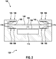
- FIG. 2 shows fine micromechanical sensor 100 which is not part of the invention.
- the illustrated micromechanical sensor 100 is set up to determine a pneumatic pressure in the environment 120 of the sensor 100.
- the cavity 115 is closed on all sides.
- the arrangement of the membrane 130 and the lever element 140 corresponds to that of the relative Figure 1 described embodiment.
- two electrodes 175 are provided on each side of each end section 145, 155 so that the first capacitive sensor (s) 180, the second capacitive sensor (s) 185 and the actuator (s) 190 can be formed independently of one another.
- the lever element 140 is completely conductive and therefore acts overall as an electrode 175.
- the actuators 190 are each shown closer to the second joint element 165 than the capacitive sensors 180, 185, but the arrangement can also be changed in other embodiments.
- Figure 3 shows a control device 300 for the micromechanical sensor 100 according to one of the preceding figures.
- the control device 300 can in particular be constructed using semiconductor technology and can be constructed preferably integrated with the micromechanical sensor 100.
- the sensor 100 comprises the control device 300.
- the control device 300 is set up to control the actuator 190 with a control voltage and to provide a signal that indicates the physical variable that can have a deflecting effect on the membrane 130 of the micromechanical sensor 100.
- the control device 300 preferably comprises a scanning device 305 for determining capacitances of the capacitive sensors 180, 185, a filter 310 for determining the control voltage, and a controllable voltage source 315 for providing the determined control voltage to the actuator 190, and preferably a processing device 320 and more preferably an interface 325.
- the capacitance of the capacitive sensors 180, 185 determined by means of the scanning device 305 or the difference between the determined capacitances indicates the pivot angle 170 of the lever element 140 down.
- the filter 310 is preferably set up to generate a control voltage that allows the pivot angle 170 to be brought either to a predetermined value or into a predetermined range.
- the physical variable which acts on the membrane 130 can be determined on the basis of the control voltage. If the swivel angle 170 is only in the predetermined range, the capacitance signal determined by means of the scanning device 305 is preferably evaluated in addition to the control voltage in order to determine the physical variable.
- the physical variable is preferably determined by the processing device 320.
- the processing device 320 can in particular comprise a programmable microcomputer or microcontroller, in a preferred embodiment in a variant as a digital signal processor (DSP).
- DSP digital signal processor
- the filter 310 can likewise be included in the processing device 320 or be constructed separately from it.
- the filter 310 can be constructed digitally, in particular using a further processing device, or analog, in particular by means of active and passive electronic components.
- the processing device 320 preferably provides a signal, in particular a voltage signal, at the interface 325, which indicates the specific physical variable.
- Figure 4 shows a flow chart of a method 400 for determining a measured variable, in particular a physical variable, which has a deflecting effect on the membrane 130 of a micromechanical sensor 100.
- the method 400 can run at least partially as a computer program product on the processing device 320 and / or the filter 310 of the control device 300. It is generally preferred that the control device 300 is set up to carry out the entire method 400.
- a step 405 capacitances of the capacitive sensors 180, 185 are determined. For this purpose, a voltage pulse can in particular be brought about on sensors 180, 185.
- the pivot angle 170 or a variable dependent thereon for example the deflection of the diaphragm 130, is determined on the basis of the determined capacities.
- the position of the lever element 140 is preferably changed in a step 420 in that the actuator 190 is controlled in a changed manner, in particular in that the control voltage of the actuator 190 is changed. If several actuators 190 are provided, their control can be changed in opposite directions. The method 400 can then return to step 405 and run through again. If, on the other hand, it is determined in step 415 that the swivel angle 170 assumes the predetermined value or range, a measure for the physical variable is preferably determined in a step 425 on the basis of the control of the actuator 190 and a signal that indicates this measure, provided. The method 400 can then likewise return to step 405 and run through again.
- the method 400 can be operated in two different variants.
- the actuator 190 is controlled in such a way that the pivot angle 170 corresponds as precisely as possible to a predetermined value.
- the physical variable can then be determined solely on the basis of the activation of the actuator 190.
- the actuator 190 is only controlled in such a way that the swivel angle 170 lies in a predetermined range in which a preferably linear relationship as possible between the physical variable and a capacitance signal which can be determined by means of the capacitive sensors 180, 185 lies.
- the control of the actuator 190 can be used as a coarse value, so to speak, while the pivot angle 170 indicates a fine value.
- the physical quantity signal can be determined based on a sum of the coarse value and the fine value. Becomes the predetermined range for the pivot angle 170 sufficiently reduced, the second variant described approaches the first.
Landscapes
- Physics & Mathematics (AREA)
- General Physics & Mathematics (AREA)
- Engineering & Computer Science (AREA)
- Computer Hardware Design (AREA)
- Microelectronics & Electronic Packaging (AREA)
- Chemical & Material Sciences (AREA)
- Analytical Chemistry (AREA)
- Pressure Sensors (AREA)
- Micromachines (AREA)
- Measuring Fluid Pressure (AREA)
Description
- Die Erfindung betrifft einen mikromechanischen Sensor. Insbesondere betrifft die Erfindung einen linearisierten Sensor, bei dem ein Zusammenhang zwischen einem abgetasteten Signal des Sensors und einer abgetasteten physikalischen Größe verbessert linearisiert ist.
- Ein mikromechanischer Sensor ist dazu eingerichtet, eine physikalische Größe abzutasten. Diese Größe kann beispielsweise eine Beschleunigung oder einen atmosphärischen Druck betreffen. Dabei ist der mikromechanische Sensor (auch mikro-elektromechanischer oder mikro-mechatronischer Sensor genannt) mit einer Ausdehnung im Bereich von ca. 20 µm bis ca. 1 mm miniaturisiert. Strukturen des mikromechanischen Sensors haben üblicherweise Ausdehnungen zwischen ca. 1 und ca. 100 µm
- Der mikromechanische Sensor umfasst üblicherweise ein Substrat und ein bewegliches Element, dessen Position bezüglich des Substrats von der zu bestimmenden physikalischen Größe abhängig ist. Die Position wird mittels eines kapazitiven Sensors bestimmt, der eine erste Elektrode, die am Substrat angebracht ist, und eine zweite Elektrode, die am beweglichen Element angebracht ist, umfasst. Eine Kapazität des Sensors ist von einem relativen Abstand der Elektroden abhängig, sodass die physikalische Größe auf der Basis der Kapazität des Sensors bestimmt werden kann. Allerdings ist der Zusammenhang zwischen der physikalischen Größe und der Kapazität oder Kapazitätsänderung des Sensors üblicherweise hochgradig nichtlinear. Die Linearität kann verbessert werden, indem mehrere kapazitive Sensoren verwendet werden, die gegenläufig durch die Bewegung des beweglichen Elements beeinflusst werden. Insbesondere kann ein Abstand zwischen Elektroden des ersten Sensors ansteigen, wenn ein Abstand zwischen den Elektroden des zweiten Sensors abnimmt und umgekehrt. Die Kapazitäten der Sensoren können einzeln bestimmt und voneinander subtrahiert werden, um ein linearisiertes, auf die physikalische Größe hinweisendes Signal bereitzustellen.
- Der Zusammenhang zwischen der physikalischen Größe bzw. der Auslenkung des beweglichen Elements und dem auf der Basis der Kapazitäten bestimmbaren Signal wird dadurch jedoch nur in einem kleinen Teilbereich ausreichend linear. Insbesondere bei einer größeren positiven oder negativen Auslenkung des beweglichen Elements, wenn der Abstand der Elektroden eines der kapazitiven Sensoren gegen null geht, verhält sich der Sensor allgemein stark nichtlinear
- Die Patentschriften
US 2015/0268115 A1 undDE 197 40 244 A1 offenbaren mikromechanische Drucksensoren gemäß dem Obergriff des Anspruchs 1. - Eine der vorliegenden Erfindung zugrunde liegende Aufgabe besteht darin, eine Technik anzugeben, mittels derer eine verbessert linearisierte Abtastung einer physikalischen Größe mittels eines mikromechanischen Sensors möglich ist. Die Erfindung löst diese Aufgabe mittels der Gegenstände der unabhängigen Ansprüche. Unteransprüche geben bevorzugte Ausführungsformen wieder.
- Die Erfindung betrifft einen mikromechanischen Sensor gemäß Anspruch 1 und die Verwendung eines Sensors gemäß Anspruch 7.
- Ein mikromechanischer Sensor umfasst ein Substrat mit einem Hohlraum; eine elastische Membran, die den Hohlraum überspannt; und ein die Membran überspannendes Hebelelement mit einem ersten und einem zweiten Endabschnitt, wobei die Endabschnitte auf gegenüberliegenden Seiten eines Mittelabschnitts liegen. Zwischen dem ersten Endabschnitt und dem Substrat ist ein erstes Gelenkelement angebracht und zwischen dem Mittelabschnitt und der Membran ist ein zweites Gelenkelement angebracht, sodass das Hebelelement aufgrund einer Auslenkung der Membran geschwenkt werden kann. Ferner sind zwei kapazitive Sensoren mit jeweils zwei Elektroden vorgesehen, wobei eine Elektrode jedes kapazitiven Sensors an einem der Endabschnitte des Hebelelements und die andere am Substrat angebracht ist. Die Elektroden der kapazitiven Sensoren sind derart angeordnet, dass Abstände zwischen den Elektroden verschiedener kapazitiver Sensoren gegenläufig beeinflusst werden, wenn das Hebelelement geschwenkt wird. Darüber hinaus umfasst der mikromechanische Sensor einen Aktuator zur Aufbringung einer Stellkraft zwischen dem Hebelelement und dem Substrat An der Membran ist ein Masseelement angebracht, wobei der Sensor zur Bestimmung einer Beschleunigung eingerichtet ist.
- Durch die Stellkraft kann der Sensor in einen Bereich gebracht werden, in dem ein Zusammenhang zwischen einer extern auf die Membran wirkenden physikalischen Größe und einem auf der Basis der Kapazitäten der Sensoren bereitgestellten Signal verbessert linearisiert ist. Ein Messbereich des Sensors oder eine Empfindlichkeit können verbessert sein. Insbesondere kann die Genauigkeit des Sensors über einen vergrößerten Messbereich hin verringerten Schwankungen unterworfen sein.
- Es ist besonders bevorzugt, dass der Aktuator auf der Basis einer elektrostatischen Anziehungskraft arbeitet. Dazu umfasst der Aktuator eine am Substrat angebrachte erste Elektrode und eine am Hebelelement angebrachte zweite Elektrode. Wird an die Elektroden eine Stellspannung angelegt, so werden die Elektroden elektrostatisch zueinander hingezogen. Die dabei wirkende Anziehungskraft ist im Wesentlichen abhängig von der Höhe der Stellspannung.
- Der elektrostatische Aktuator kann raumsparend aufgebaut sein. Zur Herstellung des Aktuators können die gleichen Prozesse wie zur Herstellung eines der kapazitiven Sensoren verwendet werden. Die elektrostatische Anziehungskraft kann schnell verändert werden und in ihrem Betrag ausreichend groß sein, um das Hebelelement zu betätigen.
- Es ist besonders bevorzugt, dass zwei Aktuatoren an unterschiedlichen Endabschnitten des Hebelelements vorgesehen sind. Insbesondere dann, wenn die Aktuatoren elektrostatisch ausgeführt sind, kann so eine resultierende Kraft auf das Hebelelement in beiden Richtungen bewirkt werden. Sind die Sensoren ebenfalls an unterschiedlichen Endabschnitten des Hebelelements vorgesehen, kann eine verbesserte Integration mit den Aktuatoren erfolgen.
- Der mikromechanische Sensor kann ferner eine Steuervorrichtung zur Ansteuerung des Aktuators und zur Bestimmung eines von der Auslenkung der Membran abhängigen Signals umfassen. Die Steuervorrichtung kann mit dem kapazitiven Sensor integriert ausgeführt sein. Sowohl der mikromechanische Sensor als auch die Steuervorrichtung können Halbleiter umfassen, die mittels der gleichen oder wenigstens ähnlicher Fertigungsverfahren hergestellt werden können. Durch die Integration können Signalpfade verkürzt und die Kompensation bzw. Vorspannung des Hebelelements zur Linearisierung der Sensorkennlinie verbessert durchgeführt werden. Eine externe Bereitstellung eines Signals zur Ansteuerung des Aktuators kann nicht erforderlich sein.
- In einer weiteren Ausführungsform ist die Steuervorrichtung dazu eingerichtet, das von der Auslenkung der Membran abhängige Signal zusätzlich auf der Basis der Kapazitäten der Sensoren zu bestimmen.
- Anders ausgedrückt kann in einer ersten Variante der Aktuator auf der Basis der Kapazitäten der Sensoren dazu angesteuert werden, das Hebelelement in eine vorbestimmte Position zu bringen, wobei das auf die physikalische Kraft, die auf die Membran wirkt, hinweisende Signal aus dem Ansteuersignal des Aktuators abgeleitet wird. In einer zweiten Variante wird das Hebelelement auf der Basis der Kapazitäten der Sensoren mittels des Aktuators in einem vorbestimmten Bereich bewegt, in dem der Zusammenhang zwischen der physikalischen Größe und dem Signal ausreichend linear ist. Das Signal wird dann als Überlagerung eines ersten Anteils, das auf der Basis der Ansteuerung des Aktuators bestimmt ist, und eines zweiten Anteils, der aus den Kapazitäten der Sensoren abgeleitet ist, bereitgestellt.
- Der beschriebene Sensor kann für unterschiedliche Zwecke genutzt werden. In einer ersten Variante ist der Hohlraum gegenüber einer Umgebung abgeschlossen, wobei der Sensor zur Bestimmung eines atmosphärischen Drucks im Außenbereich eingerichtet ist. In einer Variante besteht bevorzugt eine weitere Öffnung zwischen dem Hohlraum und dem Außenbereich.
- Ein Verfahren zum Steuern des oben beschriebenen Sensors umfasst Schritte des Bestimmens von Kapazitäten der kapazitiven Sensoren; des Ansteuerns des Aktuators in Abhängigkeit der bestimmten Kapazitäten, um einen Schwenkwinkel des Hebelelements in einen vorbestimmten Bereich zu bringen; und des Bestimmens eines von der Auslenkung der Membran abhängigen Beschleunigungssignals auf der Basis der Ansteuerung.
- Wird das Signal ausschließlich auf der Basis der Ansteuerung des Aktuators bestimmt, so ist der vorbestimmte Bereich des Schwenkwinkels üblicherweise klein. Je größer der Bereich des Schwenkwinkels ist, desto größer kann ein Messfehler sein.
- In einer anderen Ausführungsform wird das Signal zusätzlich auf der Basis der Kapazitäten der kapazitiven Sensoren bestimmt. In dieser Ausführungsform ist der vorbestimmte Bereich des Schwenkwinkels bevorzugt so gewählt, dass der Zusammenhang zwischen der physikalischen Größe, die auf die Membran wirkt, und dem auf der Basis der Sensoren bereitgestellten Signal im Wesentlichen linear ist. Dabei ist der vorbestimmte Bereich des Schwenkwinkels üblicherweise deutlich größer. Die Ansteuerung des Aktuators muss erst verändert werden, wenn der Schwenkwinkel droht, aus dem vorbestimmten Bereich zu laufen.
- Ist, wie oben genauer beschrieben wurde, der Aktuator dazu eingerichtet, eine elektrostatische Stellkraft auf das Hebelelement auszuüben, so können Elektroden eines der kapazitiven Sensoren mit den Elektroden des Aktuators zusammenfallen. Das beschriebene Verfahren kann das Ansteuern der Elektroden in rascher Folge abwechselnd als kapazitiver Sensor und als Aktuator umfassen. Ein solcher Vorgang ist unter der Bezeichnung Multiplexen bekannt. Die Elektroden können dabei einen größeren Raum einnehmen und somit im Fall des Aktuators effektiver oder im Fall des Sensors sensibler sein. Eine minimale Wechselfrequenz zwischen dem Betrieb als kapazitiver Sensor und als Aktuator richtet sich üblicherweise nach einer Trägheit des Hebelelements bezüglich seines Schwenkwinkels.
- Die Erfindung wird nun mit Bezug auf die beigefügten Figuren genauer beschrieben, in denen:
- Fig. 1
- eine schematische Darstellung eines mikromechanischen Sensors gemäß der Erfindung;
- Fig. 2
- einen mikromechanischen Sensor der nicht Teil der Erfindung ist.
- Fig. 3
- eine Steuervorrichtung 300 für den mikromechanischen Sensor nach einer der
Figuren 1 oder2 ; und - Fig. 4
- ein Ablaufdiagramm zum Bestimmen einer physikalischen Größe mittels eines mikromechanischen Sensors nach einer der
Figuren 1 oder2 -
Figur 1 zeigt eine schematische Darstellung eines mikromechanischen Sensors 100 gemäß der Erfindung. In exemplarischer Weise ist die dargestellte Ausführungsform des Sensors 100 zur Bestimmung einer Beschleunigung, in der Darstellung vonFigur 1 in vertikaler Richtung, eingerichtet. - Der Sensor 100 umfasst ein Substrat 110, das üblicherweise Silizium oder ein anderes Halbleitermaterial umfasst, wobei im Substrat 110 ein Hohlraum 115 ausgebildet ist. Zum Ausgleichen eines atmosphärischen Drucks zwischen dem Hohlraum 115 und einer Umgebung 120 kann eine Öffnung 125 vorgesehen sein. Über dem Hohlraum 115 ist eine Membran 130 gespannt, die wie das Substrat 110 ein Halbleitermaterial umfassen kann. An ihren Rändern ist die Membran 130 bevorzugt mit dem Substrat 110 verbunden. In einer bevorzugten Ausführungsform ist ein Masseelement 135 an der Membran 130 angebracht, und zwar bevorzugt nahe ihrer Mitte. Wird das Substrat 110 in der Darstellung von
Figur 1 in vertikaler Richtung beschleunigt, so bewirkt die Massenträgheit des Masseelements 135 eine vertikale Auslenkung der Membran 130. Das Masseelement umfasst bevorzugt ebenfalls ein Halbleitermaterial. - Über die Membran 130 ist ein Hebelelement 140 gespannt, das einen ersten Endabschnitt 145, einen Mittelabschnitt 150 und einen zweiten Endabschnitt 155 aufweist. Die Endabschnitte 145 und 155 liegen auf unterschiedlichen Seiten des Mittelabschnitts 150. Das gesamte Hebelelement 140 ist daher bevorzugt stabförmig ausgebildet. Ein erstes Gelenkelement 160 ist zwischen dem ersten Endabschnitt 145 und dem Substrat 110 angebracht. Ein zweites Gelenkelement 165 ist zwischen dem Mittelabschnitt 150 und der Membran 130 angebracht. Dabei greift das zweite Gelenkelement 165 bevorzugt in einem Bereich nahe der Mitte der Membran 130 an. Das erste Gelenkelement 160 als auch das zweite Gelenkelement 165 können als separates Element zwischen Hebelelement 140 und Substrat 110 bzw. Membran 130 ausgestaltet sein. Ebenso kann vorgesehen sein, dass wenigstens eine Verbindung eines der Gelenkelemente integral mit dem Hebelelement bzw. dem Substrat und/oder der Membran verbunden ist. Besonders bevorzugt ist, dass wenigstens ein Gelenkelement an einem Ende mit dem Material des Hebelelements und am anderen Ende mit dem Material des Substrats bzw. der Membran integral verbunden ist. Die Gelenkelemente 160 und 165 umfassen bevorzugt ebenfalls Halbleitermaterial.
- Das Hebelelement 140 ist mittels der Gelenkelemente 160 und 165 derart schwenkbar bezüglich dem Substrat 110 angebracht, dass ein Schwenkwinkel 170 von einer Auslenkung der Membran 130 abhängig ist. Hebt sich der erste Endabschnitt 145, so senkt sich der zweite Endabschnitt 155 und umgekehrt.
- Dabei ist das Substrat 110 im Bereich der Endabschnitte 145 und 155 bevorzugt so geformt, dass jeweils zwei Abschnitte des Substrats 110 auf unterschiedlichen Seiten jedes Endabschnitts 145, 155 bezüglich der Schwenkrichtung des Hebelelements 140 liegen.
- An jedem dieser Abschnitte kann eine Elektrode 175 vorgesehen sein. Jeweils eine weitere Elektrode 175 kann an jedem der Endabschnitte 145, 155 des Hebelelements 140 vorgesehen sein. Alternativ dazu kann das Hebelelement 140 auch vollständig aus einem leitfähigen Material, insbesondere einem Metall, hergestellt sein. Zwei erste kapazitive Sensoren 180 umfassen jeweils eine Elektrode 175, die an unterschiedlichen Endabschnitten 145, 155 des Hebelelements 140 angebracht sind, und weitere Elektroden 175, die am Substrat 110 angebracht sind, wobei sich Abstände zwischen den Elektroden 175 jedes ersten kapazitiven Sensors 180 verkleinern, wenn das Hebelelement 140 im Uhrzeigersinn verschwenkt wird. Ferner sind zwei zweite kapazitive Sensoren 185 gebildet, die jeweils eine an unterschiedlichen Endabschnitten 145, 155 des Hebelelements 140 angebrachte Elektrode 175 und zwei am Substrat 110 angebrachte Elektroden 175 umfassen, wobei Abstände zwischen den Elektroden 175 der zweiten kapazitiven Sensoren 185 verkleinert werden, wenn das Hebelelement 140 im Uhrzeigersinn verschwenkt wird.
- In anderen Ausführungsformen sind nur ein erster kapazitiver Sensor 180 und/oder nur ein zweiter kapazitiver Sensor 185 vorgesehen. Mehrere kapazitive Sensoren 180, 185 werden üblicherweise elektrisch parallel geschaltet, um die wirksamen Flächen der beteiligten Elektroden 175 zu vergrößern, sodass der Sensor 180, 185 ein größeres elektrisches Signal in Abhängigkeit einer mechanischen Verschwenkung bereitstellt.
- Eine Kapazität eines der Sensoren 180, 185 kann beispielsweise mittels eines Spannungspulses bestimmt werden. Die Kapazität jedes Sensors 180, 185 ist üblicherweise umgekehrt proportional zu einem Abstand der beteiligten Elektroden 175. Der Abstand hängt vom Schwenkwinkel 170 und dieser von einer Auslenkung der Membran 130 ab. Auf diese Weise ist eine physikalische Größe, hier eine Beschleunigung, die auf die Auslenkung der Membran 130 wirkt, ursächlich für eine Veränderung der Kapazitäten der kapazitiven Sensoren 180 und 185. Der Zusammenhang zwischen der physikalischen Größe und einer bestimmten Kapazität kann verbessert linearisiert werden, indem die bestimmte Kapazität des ersten kapazitiven Sensors 180 von der bestimmten Kapazität des zweiten kapazitiven Sensors 185 abgezogen wird oder umgekehrt.
- Trotzdem ist der Zusammenhang üblicherweise nur für einen relativ kleinen Bereich des Schwenkwinkels 170 linear. Um die Linearität zu verbessern, wird daher vorgeschlagen, einen Aktuator 190 vorzusehen, der eine vorbestimmte Kraft auf das Hebelelement 140 ausübt, um den Schwenkwinkel 170 in einen Bereich zu bringen, in dem der genannte Zusammenhang ausreichend linear ist. Dazu kann ein Paar von Elektroden 175, das dann nicht zur Bildung eines ersten kapazitiven Sensors 180 oder eines zweiten kapazitiven Sensors 185 zur Verfügung steht, mit einer vorbestimmten Stellspannung beaufschlagt werden. In dieser Ausführungsform kann durch einen Aktuator 190 nur eine Anziehungskraft, aber keine Abstoßungskraft ausgeübt werden. Es ist daher bevorzugt, dass zwei der beschriebenen elektrostatischen Aktuatoren 190 an unterschiedlichen Endabschnitten 145, 155 des Hebelelements 140 vorgesehen sind. Ein Paar von Elektroden 175 kann auch alternierend als kapazitiver Sensor 180, 185 und als Aktuator 190 betrieben werden. In einer anderen Ausführungsform kann auch eine andere Art von Aktuator 190 vorgesehen sein, beispielsweise auf der Basis eines Piezoelements.
-
Figur 2 zeigt feinen mikromechanischen Sensor 100 der nicht Teil der Erfindung ist. Der dargestellte mikromechanische Sensor 100 ist dazu eingerichtet, einen pneumatischen Druck in der Umgebung 120 des Sensors 100 zu bestimmen. Dazu ist der Hohlraum 115 auf allen Seiten abgeschlossen. Die Anordnung der Membran 130 und des Hebelelements 140 entspricht der von der bezüglichFigur 1 beschriebenen Ausführungsform. In der dargestellten Ausführungsform sind auf jeder Seite jedes Endabschnitts 145, 155 jeweils zwei Elektroden 175 vorgesehen, sodass der oder die ersten kapazitiven Sensoren 180, der oder die zweiten kapazitiven Sensoren 185 und der oder die Aktuatoren 190 unabhängig voneinander gebildet werden können. In der dargestellten Ausführungsform ist das Hebelelement 140 vollständig leitfähig und wirkt daher insgesamt als Elektrode 175. Rein beispielhaft sind die Aktuatoren 190 jeweils näher am zweiten Gelenkelement 165 als die kapazitiven Sensoren 180, 185 dargestellt, in anderen Ausführungsformen kann die Anordnung jedoch auch verändert sein. -
Figur 3 zeigt eine Steuervorrichtung 300 für den mikromechanischen Sensor 100 nach einer der vorangehenden Figuren. Die Steuervorrichtung 300 kann insbesondere in Halbleitertechnik aufgebaut und bevorzugt mit dem mikromechanischen Sensor 100 integriert aufgebaut sein. In einer Ausführungsform umfasst der Sensor 100 die Steuervorrichtung 300. Die Steuervorrichtung 300 ist dazu eingerichtet, den Aktuator 190 mit einer Stellspannung anzusteuern und ein Signal bereitzustellen, das auf die physikalische Größe hinweist, die auf die Membran 130 des mikromechanischen Sensors 100 auslenkend wirken kann. - Die Steuervorrichtung 300 umfasst bevorzugt eine Abtasteinrichtung 305 zur Bestimmung von Kapazitäten der kapazitiven Sensoren 180, 185, einen Filter 310 zur Bestimmung der Stellspannung, eine steuerbare Spannungsquelle 315 zur Bereitstellung der bestimmten Stellspannung an den Aktuator 190, sowie bevorzugt eine Verarbeitungseinrichtung 320 und weiter bevorzugt eine Schnittstelle 325. Die mittels der Abtasteinrichtung 305 bestimmte Kapazität der kapazitiven Sensoren 180, 185 bzw. die Differenz der bestimmten Kapazitäten weist auf den Schwenkwinkel 170 des Hebelelements 140 hin. Der Filter 310 ist bevorzugt dazu eingerichtet, eine Stellspannung zu generieren, die es erlaubt, den Schwenkwinkel 170 entweder auf einen vorbestimmten Wert oder in einen vorbestimmten Bereich zu bringen. Entspricht der Schwenkwinkel 170 dem vorbestimmten Wert, so kann die physikalische Größe, die auf die Membran 130 wirkt, auf der Basis der Stellspannung bestimmt werden. Liegt der Schwenkwinkel 170 lediglich im vorbestimmten Bereich, so wird bevorzugt zusätzlich zur Stellspannung das mittels der Abtasteinrichtung 305 bestimmte Kapazitätssignal zusätzlich ausgewertet, um die physikalische Größe zu bestimmen. Die physikalische Größe wird in beiden Varianten bevorzugt durch die Verarbeitungseinrichtung 320 bestimmt. Dazu kann die Verarbeitungseinrichtung 320 insbesondere einen programmierbaren Mikrocomputer oder Mikrocontroller, in einer bevorzugten Ausführungsform in einer Variante als digitaler Signalprozessor (DSP), umfassen. Der Filter 310 kann ebenfalls von der Verarbeitungseinrichtung 320 umfasst sein oder getrennt von diesem aufgebaut sein. Dabei kann der Filter 310 digital, insbesondere unter Verwendung einer weiteren Verarbeitungseinrichtung, oder analog, insbesondere mittels aktiver und passiver elektronischer Komponenten, aufgebaut werden. Die Verarbeitungseinrichtung 320 stellt bevorzugt an der Schnittstelle 325 ein Signal, insbesondere ein Spannungssignal, bereit, das auf die bestimmte physikalische Größe hinweist.
-
Figur 4 zeigt ein Ablaufdiagramm eines Verfahrens 400 zum Bestimmen einer Messgröße, insbesondere einer physikalischen Größe, die auslenkend auf die Membran 130 eines mikromechanischen Sensors 100 einwirkt. Das Verfahren 400 kann zumindest teilweise als Computerprogrammprodukt auf der Verarbeitungseinrichtung 320 und/oder dem Filter 310 der Steuervorrichtung 300 ablaufen. Es ist allgemein bevorzugt, dass die Steuervorrichtung 300 zur Durchführung des gesamten Verfahrens 400 eingerichtet ist. - In einem Schritt 405 werden Kapazitäten der kapazitiven Sensoren 180, 185 bestimmt. Dazu kann insbesondere ein Spannungspuls auf die Sensoren 180, 185 bewirkt werden. In einem nachfolgenden Schritt 410 wird auf der Basis der bestimmten Kapazitäten der Schwenkwinkel 170 oder eine davon abhängige Größe, beispielsweise die Auslenkung der Membran 130, bestimmt. In einem Schritt 415 wird dann bevorzugt überprüft, ob sich der mikromechanische Sensor 100 in einem vorbestimmten Bereich befindet. Dies ist dann der Fall, wenn der Schwenkwinkel 170 einen vorbestimmten Bereich oder Wert annimmt oder die entsprechende Größe einen korrespondierenden Wert oder Bereich einnimmt. Befindet sich der mikromechanische Sensor 100 nicht im vorbestimmten Bereich, so wird bevorzugt in einem Schritt 420 die Stellung des Hebelelements 140 verändert, indem der Aktuator 190 verändert angesteuert wird, insbesondere indem die Stellspannung des Aktuators 190 verändert wird. Sind mehrere Aktuatoren 190 vorgesehen, so kann deren Ansteuerung gegenläufig verändert werden. Anschließend kann das Verfahren 400 zum Schritt 405 zurückkehren und erneut durchlaufen. Wird hingegen im Schritt 415 bestimmt, dass der Schwenkwinkel 170 den vorbestimmten Wert oder Bereich einnimmt, so wird bevorzugt in einem Schritt 425 auf der Basis der Ansteuerung des Aktuators 190 ein Maß für die physikalische Größe bestimmt und ein Signal, das auf dieses Maß hinweist, bereitgestellt. Anschließend kann das Verfahren 400 ebenfalls zum Schritt 405 zurückkehren und erneut durchlaufen.
- Das Verfahren 400 kann in zwei unterschiedlichen Varianten betrieben werden. In einer ersten Variante wird der Aktuator 190 derart angesteuert, dass der Schwenkwinkel 170 möglichst genau einem vorbestimmten Wert entspricht. Die physikalische Größe kann dann allein auf der Basis der Ansteuerung des Aktuators 190 bestimmt werden. In einer zweiten Variante wird der Aktuator 190 nur so angesteuert, dass der Schwenkwinkel 170 in einem vorbestimmten Bereich liegt, in dem bevorzugt ein möglichst linearer Zusammenhang zwischen der physikalischen Größe und einem mittels der kapazitiven Sensoren 180, 185 bestimmbaren Kapazitätssignal liegt. In diesem Fall kann die Ansteuerung des Aktuators 190 gewissermaßen als Grobwert verwendet werden, während der Schwenkwinkel 170 einen Feinwert anzeigt. Das Signal für die physikalische Größe kann auf der Basis einer Summe des Grobwerts und des Feinwerts bestimmt werden. Wird der vorbestimmte Bereich für den Schwenkwinkel 170 ausreichend verkleinert, so nähert sich die zweite beschriebene Variante an die erste an.
Claims (9)
- Mikromechanischer Sensor (100), umfassend:- ein Substrat (110) mit einem Hohlraum (115);- eine elastische Membran (130), die den Hohlraum (115) überspannt;- ein die Membran (130) überspannendes Hebelelement (140) mit einem ersten (145) und einem zweiten Endabschnitt (155) und einem Mittelabschnitt (150), wobei die Endabschnitte (145, 155) auf gegenüberliegenden Seiten des Mittelabschnitts (150) liegen;- ein erstes Gelenkelement (160), das zwischen dem ersten Endabschnitt (145) und dem Substrat (110) angebracht ist;- ein zweites Gelenkelement (165), das zwischen dem Mittelabschnitt (150) und der Membran (130) angebracht ist;- einen ersten und einen zweiten kapazitiven Sensor (180, 185), wobei jeder kapazitive Sensor (180, 185) zwei Elektroden (175) aufweist, von denen eine an einem der Endabschnitte (145, 155) und die andere am Substrat (110) angebracht ist,- sodass Abstände zwischen den Elektroden (175) verschiedener kapazitiver Sensoren (180, 185) gegenläufig beeinflusst werden, wenn das Hebelelement (140) aufgrund einer Auslenkung der Membran (130) geschwenkt wird, und- einen Aktuator (190) zur Aufbringung einer Stellkraft zwischen dem Hebelelement (140) und dem Substrat (110),dadurch gekennzeichnet, dass
an der Membran (130) ein Masseelement (135) angebracht ist und der Sensor (100) zur Bestimmung einer Beschleunigung eingerichtet ist. - Sensor (100) nach Anspruch 1, wobei der Aktuator (190) eine am Substrat (110) angebrachte erste Elektrode (175) und eine am Hebelelement (140) angebrachte zweite Elektrode (175) umfasst, um eine elektrostatische Anziehungskraft bereitzustellen, wenn an die Elektroden (175) eine Stellspannung angelegt ist.
- Sensor (100) nach Anspruch 2, wobei zwei Aktuatoren (190) an unterschiedlichen Endabschnitten (145, 155) des Hebelelements (140) vorgesehen sind.
- Sensor (100) nach einem der vorangehenden Ansprüche, ferner umfassend eine Steuervorrichtung (300) zur Ansteuerung des Aktuators (190) und zur Bestimmung eines von der Auslenkung der Membran (130) abhängigen Signals.
- Sensor (100) nach Anspruch 4, wobei die Steuervorrichtung (300) dazu eingerichtet ist, das von der Auslenkung der Membran (130) abhängige Signal zusätzlich auf der Basis der Kapazitäten der kapazitiven Sensoren (180, 185) zu bestimmen.
- Sensor (100) nach einem der vorangehenden Ansprüche, wobei der Hohlraum (115) gegenüber einer Umgebung (120) abgeschlossen ist und der Sensor (100) zur Bestimmung eines atmosphärischen Drucks in der Umgebung (120) eingerichtet ist.
- Verfahren (400) zum Steuern eines Sensors (100) nach einem der vorangehenden Ansprüche, wobei das Verfahren (400) folgende Schritte umfasst:- Bestimmen (405) von Kapazitäten der kapazitiven Sensoren (180, 185);- Ansteuern (420) des Aktuators (190) in Abhängigkeit der bestimmten Kapazitäten, um einen Schwenkwinkel (170) des Hebelelements (140) in einen vorbestimmten Bereich zu bringen; und- Bestimmen (425) eines von der Auslenkung der Membran (130) abhängigen Beschleunigungssignals auf der Basis der Ansteuerung.
- Verfahren (400) nach Anspruch 7, wobei das Signal zusätzlich auf der Basis der Kapazitäten der kapazitiven Sensoren (180, 185) bestimmt (425) wird.
- Verfahren (400) nach Anspruch 7 oder 8, bezogen auf Anspruch 2, wobei die Elektroden (175) eines der kapazitiven Sensoren (180, 185) mit den Elektroden (175) des Aktuators (190) zusammenfallen und das Verfahren (400) das Ansteuern der Elektroden (175) in rascher Folge abwechselnd als kapazitiver Sensor (180, 185) und als Aktuator (190) umfasst.
Applications Claiming Priority (2)
| Application Number | Priority Date | Filing Date | Title |
|---|---|---|---|
| DE102017200057.0A DE102017200057A1 (de) | 2017-01-04 | 2017-01-04 | Linearisierter mikromechanischer Sensor |
| PCT/EP2017/081938 WO2018127352A1 (de) | 2017-01-04 | 2017-12-08 | Linearisierter mikromechanischer sensor |
Publications (2)
| Publication Number | Publication Date |
|---|---|
| EP3566037A1 EP3566037A1 (de) | 2019-11-13 |
| EP3566037B1 true EP3566037B1 (de) | 2021-02-24 |
Family
ID=60702698
Family Applications (1)
| Application Number | Title | Priority Date | Filing Date |
|---|---|---|---|
| EP17816653.4A Active EP3566037B1 (de) | 2017-01-04 | 2017-12-08 | Linearisierter mikromechanischer sensor |
Country Status (5)
| Country | Link |
|---|---|
| US (1) | US11326969B2 (de) |
| EP (1) | EP3566037B1 (de) |
| DE (1) | DE102017200057A1 (de) |
| TW (1) | TW201827329A (de) |
| WO (1) | WO2018127352A1 (de) |
Families Citing this family (6)
| Publication number | Priority date | Publication date | Assignee | Title |
|---|---|---|---|---|
| DE102016209241B4 (de) * | 2016-05-27 | 2025-07-03 | Robert Bosch Gmbh | Mikromechanisches Bauteil für eine Drucksensorvorrichtung |
| FR3098810B1 (fr) * | 2019-07-18 | 2021-10-15 | Commissariat Energie Atomique | Liaison mécanique pour dispositif MEMS et NEMS de mesure d'une variation de pression et dispositif comprenant une telle liaison mécanique |
| DE102020214757A1 (de) * | 2020-11-25 | 2022-05-25 | Robert Bosch Gesellschaft mit beschränkter Haftung | Sensorvorrichtung und Verfahren zum Detektieren eines Innendrucks und/oder einer Änderung des Innendrucks in einem gasdicht abgeschlossenen Innenvolumen einer Gehäusekomponente |
| FR3123343B1 (fr) * | 2021-05-31 | 2023-05-19 | Commissariat Energie Atomique | Microsystème électromécanique |
| DE102023123559A1 (de) | 2023-09-01 | 2025-03-06 | Valeo Schalter Und Sensoren Gmbh | Kraftsensor mit spezifischen kapazitiven Sensoren, sowie Eingabevorrichtung |
| DE102024205838A1 (de) * | 2024-06-24 | 2025-12-24 | Robert Bosch Gesellschaft mit beschränkter Haftung | MEMS-Vorrichtung |
Family Cites Families (6)
| Publication number | Priority date | Publication date | Assignee | Title |
|---|---|---|---|---|
| US5177579A (en) * | 1989-04-07 | 1993-01-05 | Ic Sensors, Inc. | Semiconductor transducer or actuator utilizing corrugated supports |
| DE19740244A1 (de) | 1997-09-12 | 1998-02-26 | Klaus Prof Dr Ing Bethe | Beschleunigungs-unempfindlicher, planarer Differenzdruck-Sensor in Mikrotechnik |
| FR2977319B1 (fr) * | 2011-07-01 | 2014-03-14 | Commissariat Energie Atomique | Dispositif de mesure de pression a sensiblite optimisee |
| US9290067B2 (en) | 2012-08-30 | 2016-03-22 | Freescale Semiconductor, Inc. | Pressure sensor with differential capacitive output |
| FR3018916B1 (fr) * | 2014-03-19 | 2017-08-25 | Commissariat Energie Atomique | Capteur de mesure de pression differentielle microelectromecanique et/ou nanoelectromecanique |
| JP6430355B2 (ja) * | 2015-10-16 | 2018-11-28 | 株式会社東芝 | センサ装置 |
-
2017
- 2017-01-04 DE DE102017200057.0A patent/DE102017200057A1/de not_active Withdrawn
- 2017-12-08 EP EP17816653.4A patent/EP3566037B1/de active Active
- 2017-12-08 US US16/471,221 patent/US11326969B2/en active Active
- 2017-12-08 WO PCT/EP2017/081938 patent/WO2018127352A1/de not_active Ceased
-
2018
- 2018-01-03 TW TW107100207A patent/TW201827329A/zh unknown
Non-Patent Citations (1)
| Title |
|---|
| None * |
Also Published As
| Publication number | Publication date |
|---|---|
| DE102017200057A1 (de) | 2018-07-05 |
| US20200088598A1 (en) | 2020-03-19 |
| EP3566037A1 (de) | 2019-11-13 |
| WO2018127352A1 (de) | 2018-07-12 |
| US11326969B2 (en) | 2022-05-10 |
| TW201827329A (zh) | 2018-08-01 |
Similar Documents
| Publication | Publication Date | Title |
|---|---|---|
| EP3566037B1 (de) | Linearisierter mikromechanischer sensor | |
| DE69432074T2 (de) | Mikromechanischer querbeschleunigungsmesser | |
| DE102009000167B4 (de) | Sensoranordnung | |
| DE102010029645B4 (de) | Mikromechanisches Bauelement mit einer Teststruktur zur Bestimmung der Schichtdicke einer Abstandsschicht und Verfahren zum Herstellen einer solchen Teststruktur | |
| DE102009046807B4 (de) | Verfahren zur Empfindlichkeitsbestimmung eines Beschleunigungs- oder Magnetfeldsensors | |
| DE102017219901B3 (de) | Mikromechanischer z-Inertialsensor | |
| DE102014223886A1 (de) | MEMS-Vorrichtung | |
| WO2012156293A1 (de) | Kraftaufnehmer, insbesondere kapazitive wägezelle | |
| EP2207020B1 (de) | Kapazitiver Drucksensor | |
| DE102005005554B4 (de) | Verfahren zur Überprüfung eines Halbleitersensors für eine dynamische Grösse | |
| DE102013208688A1 (de) | Sensiereinrichtung für eine mikromechanische Sensorvorrichtung | |
| DE102017219929B4 (de) | Mikromechanischer z-Inertialsensor | |
| DE102015212669A1 (de) | Kapazitive mikroelektromechanische Vorrichtung und Verfahren zum Ausbilden einer kapazitiven mikroelektromechanischen Vorrichtung | |
| EP3063518B1 (de) | Kapazitives sensorelement mit integrierter mess- und referenzkapazität | |
| EP2138450B1 (de) | Elektrodenstruktur für ein mikromechanisches Bauelement | |
| WO2017202611A1 (de) | Mikromechanisches bauteil für eine drucksensorvorrichtung | |
| EP3504152B1 (de) | Mikromechanisches bauteil mit zwei membranen und herstellungsverfahren für ein mikromechanisches bauteil mit zwei membranen | |
| EP1332374B1 (de) | Verfahren und vorrichtung zum elektrischen nullpunktabgleich für ein mikromechanisches bauelement | |
| EP2593760B1 (de) | Infrarot-sensor mit tunnelkontakt zur messung der verformung einer membran | |
| DE19847563A1 (de) | Kapazitiver Sensor | |
| WO2010124889A2 (de) | Messelement | |
| DE102019201235A1 (de) | Drucksensoreinrichtung sowie Verfahren zum Herstellen einer Drucksensoreinrichtung | |
| WO2022117494A1 (de) | Mikromechanische sensorstruktur mit dämpfungsstruktur | |
| DE102007054027B4 (de) | Vorrichtung und Verfahren zur kapazitiven Kraftmessung | |
| EP4193377A1 (de) | Elektronikmodul und anlage |
Legal Events
| Date | Code | Title | Description |
|---|---|---|---|
| STAA | Information on the status of an ep patent application or granted ep patent |
Free format text: STATUS: UNKNOWN |
|
| STAA | Information on the status of an ep patent application or granted ep patent |
Free format text: STATUS: THE INTERNATIONAL PUBLICATION HAS BEEN MADE |
|
| PUAI | Public reference made under article 153(3) epc to a published international application that has entered the european phase |
Free format text: ORIGINAL CODE: 0009012 |
|
| STAA | Information on the status of an ep patent application or granted ep patent |
Free format text: STATUS: REQUEST FOR EXAMINATION WAS MADE |
|
| 17P | Request for examination filed |
Effective date: 20190805 |
|
| AK | Designated contracting states |
Kind code of ref document: A1 Designated state(s): AL AT BE BG CH CY CZ DE DK EE ES FI FR GB GR HR HU IE IS IT LI LT LU LV MC MK MT NL NO PL PT RO RS SE SI SK SM TR |
|
| AX | Request for extension of the european patent |
Extension state: BA ME |
|
| DAV | Request for validation of the european patent (deleted) | ||
| DAX | Request for extension of the european patent (deleted) | ||
| RAP1 | Party data changed (applicant data changed or rights of an application transferred) |
Owner name: ROBERT BOSCH GMBH |
|
| GRAP | Despatch of communication of intention to grant a patent |
Free format text: ORIGINAL CODE: EPIDOSNIGR1 |
|
| STAA | Information on the status of an ep patent application or granted ep patent |
Free format text: STATUS: GRANT OF PATENT IS INTENDED |
|
| INTG | Intention to grant announced |
Effective date: 20201120 |
|
| GRAS | Grant fee paid |
Free format text: ORIGINAL CODE: EPIDOSNIGR3 |
|
| GRAA | (expected) grant |
Free format text: ORIGINAL CODE: 0009210 |
|
| STAA | Information on the status of an ep patent application or granted ep patent |
Free format text: STATUS: THE PATENT HAS BEEN GRANTED |
|
| AK | Designated contracting states |
Kind code of ref document: B1 Designated state(s): AL AT BE BG CH CY CZ DE DK EE ES FI FR GB GR HR HU IE IS IT LI LT LU LV MC MK MT NL NO PL PT RO RS SE SI SK SM TR |
|
| REG | Reference to a national code |
Ref country code: CH Ref legal event code: EP |
|
| REG | Reference to a national code |
Ref country code: AT Ref legal event code: REF Ref document number: 1365076 Country of ref document: AT Kind code of ref document: T Effective date: 20210315 |
|
| REG | Reference to a national code |
Ref country code: IE Ref legal event code: FG4D Free format text: LANGUAGE OF EP DOCUMENT: GERMAN |
|
| REG | Reference to a national code |
Ref country code: DE Ref legal event code: R096 Ref document number: 502017009523 Country of ref document: DE |
|
| REG | Reference to a national code |
Ref country code: LT Ref legal event code: MG9D |
|
| REG | Reference to a national code |
Ref country code: NL Ref legal event code: MP Effective date: 20210224 |
|
| PG25 | Lapsed in a contracting state [announced via postgrant information from national office to epo] |
Ref country code: FI Free format text: LAPSE BECAUSE OF FAILURE TO SUBMIT A TRANSLATION OF THE DESCRIPTION OR TO PAY THE FEE WITHIN THE PRESCRIBED TIME-LIMIT Effective date: 20210224 Ref country code: GR Free format text: LAPSE BECAUSE OF FAILURE TO SUBMIT A TRANSLATION OF THE DESCRIPTION OR TO PAY THE FEE WITHIN THE PRESCRIBED TIME-LIMIT Effective date: 20210525 Ref country code: HR Free format text: LAPSE BECAUSE OF FAILURE TO SUBMIT A TRANSLATION OF THE DESCRIPTION OR TO PAY THE FEE WITHIN THE PRESCRIBED TIME-LIMIT Effective date: 20210224 Ref country code: PT Free format text: LAPSE BECAUSE OF FAILURE TO SUBMIT A TRANSLATION OF THE DESCRIPTION OR TO PAY THE FEE WITHIN THE PRESCRIBED TIME-LIMIT Effective date: 20210624 Ref country code: NO Free format text: LAPSE BECAUSE OF FAILURE TO SUBMIT A TRANSLATION OF THE DESCRIPTION OR TO PAY THE FEE WITHIN THE PRESCRIBED TIME-LIMIT Effective date: 20210524 Ref country code: BG Free format text: LAPSE BECAUSE OF FAILURE TO SUBMIT A TRANSLATION OF THE DESCRIPTION OR TO PAY THE FEE WITHIN THE PRESCRIBED TIME-LIMIT Effective date: 20210524 Ref country code: LT Free format text: LAPSE BECAUSE OF FAILURE TO SUBMIT A TRANSLATION OF THE DESCRIPTION OR TO PAY THE FEE WITHIN THE PRESCRIBED TIME-LIMIT Effective date: 20210224 |
|
| PG25 | Lapsed in a contracting state [announced via postgrant information from national office to epo] |
Ref country code: RS Free format text: LAPSE BECAUSE OF FAILURE TO SUBMIT A TRANSLATION OF THE DESCRIPTION OR TO PAY THE FEE WITHIN THE PRESCRIBED TIME-LIMIT Effective date: 20210224 Ref country code: NL Free format text: LAPSE BECAUSE OF FAILURE TO SUBMIT A TRANSLATION OF THE DESCRIPTION OR TO PAY THE FEE WITHIN THE PRESCRIBED TIME-LIMIT Effective date: 20210224 Ref country code: LV Free format text: LAPSE BECAUSE OF FAILURE TO SUBMIT A TRANSLATION OF THE DESCRIPTION OR TO PAY THE FEE WITHIN THE PRESCRIBED TIME-LIMIT Effective date: 20210224 Ref country code: PL Free format text: LAPSE BECAUSE OF FAILURE TO SUBMIT A TRANSLATION OF THE DESCRIPTION OR TO PAY THE FEE WITHIN THE PRESCRIBED TIME-LIMIT Effective date: 20210224 Ref country code: SE Free format text: LAPSE BECAUSE OF FAILURE TO SUBMIT A TRANSLATION OF THE DESCRIPTION OR TO PAY THE FEE WITHIN THE PRESCRIBED TIME-LIMIT Effective date: 20210224 |
|
| PG25 | Lapsed in a contracting state [announced via postgrant information from national office to epo] |
Ref country code: IS Free format text: LAPSE BECAUSE OF FAILURE TO SUBMIT A TRANSLATION OF THE DESCRIPTION OR TO PAY THE FEE WITHIN THE PRESCRIBED TIME-LIMIT Effective date: 20210624 |
|
| PG25 | Lapsed in a contracting state [announced via postgrant information from national office to epo] |
Ref country code: EE Free format text: LAPSE BECAUSE OF FAILURE TO SUBMIT A TRANSLATION OF THE DESCRIPTION OR TO PAY THE FEE WITHIN THE PRESCRIBED TIME-LIMIT Effective date: 20210224 Ref country code: CZ Free format text: LAPSE BECAUSE OF FAILURE TO SUBMIT A TRANSLATION OF THE DESCRIPTION OR TO PAY THE FEE WITHIN THE PRESCRIBED TIME-LIMIT Effective date: 20210224 Ref country code: SM Free format text: LAPSE BECAUSE OF FAILURE TO SUBMIT A TRANSLATION OF THE DESCRIPTION OR TO PAY THE FEE WITHIN THE PRESCRIBED TIME-LIMIT Effective date: 20210224 |
|
| REG | Reference to a national code |
Ref country code: DE Ref legal event code: R097 Ref document number: 502017009523 Country of ref document: DE |
|
| PG25 | Lapsed in a contracting state [announced via postgrant information from national office to epo] |
Ref country code: RO Free format text: LAPSE BECAUSE OF FAILURE TO SUBMIT A TRANSLATION OF THE DESCRIPTION OR TO PAY THE FEE WITHIN THE PRESCRIBED TIME-LIMIT Effective date: 20210224 Ref country code: SK Free format text: LAPSE BECAUSE OF FAILURE TO SUBMIT A TRANSLATION OF THE DESCRIPTION OR TO PAY THE FEE WITHIN THE PRESCRIBED TIME-LIMIT Effective date: 20210224 Ref country code: DK Free format text: LAPSE BECAUSE OF FAILURE TO SUBMIT A TRANSLATION OF THE DESCRIPTION OR TO PAY THE FEE WITHIN THE PRESCRIBED TIME-LIMIT Effective date: 20210224 |
|
| PLBE | No opposition filed within time limit |
Free format text: ORIGINAL CODE: 0009261 |
|
| STAA | Information on the status of an ep patent application or granted ep patent |
Free format text: STATUS: NO OPPOSITION FILED WITHIN TIME LIMIT |
|
| PG25 | Lapsed in a contracting state [announced via postgrant information from national office to epo] |
Ref country code: ES Free format text: LAPSE BECAUSE OF FAILURE TO SUBMIT A TRANSLATION OF THE DESCRIPTION OR TO PAY THE FEE WITHIN THE PRESCRIBED TIME-LIMIT Effective date: 20210224 Ref country code: AL Free format text: LAPSE BECAUSE OF FAILURE TO SUBMIT A TRANSLATION OF THE DESCRIPTION OR TO PAY THE FEE WITHIN THE PRESCRIBED TIME-LIMIT Effective date: 20210224 |
|
| 26N | No opposition filed |
Effective date: 20211125 |
|
| PG25 | Lapsed in a contracting state [announced via postgrant information from national office to epo] |
Ref country code: SI Free format text: LAPSE BECAUSE OF FAILURE TO SUBMIT A TRANSLATION OF THE DESCRIPTION OR TO PAY THE FEE WITHIN THE PRESCRIBED TIME-LIMIT Effective date: 20210224 |
|
| PG25 | Lapsed in a contracting state [announced via postgrant information from national office to epo] |
Ref country code: IS Free format text: LAPSE BECAUSE OF FAILURE TO SUBMIT A TRANSLATION OF THE DESCRIPTION OR TO PAY THE FEE WITHIN THE PRESCRIBED TIME-LIMIT Effective date: 20210624 |
|
| PG25 | Lapsed in a contracting state [announced via postgrant information from national office to epo] |
Ref country code: MC Free format text: LAPSE BECAUSE OF FAILURE TO SUBMIT A TRANSLATION OF THE DESCRIPTION OR TO PAY THE FEE WITHIN THE PRESCRIBED TIME-LIMIT Effective date: 20210224 |
|
| REG | Reference to a national code |
Ref country code: CH Ref legal event code: PL |
|
| GBPC | Gb: european patent ceased through non-payment of renewal fee |
Effective date: 20211208 |
|
| REG | Reference to a national code |
Ref country code: BE Ref legal event code: MM Effective date: 20211231 |
|
| PG25 | Lapsed in a contracting state [announced via postgrant information from national office to epo] |
Ref country code: LU Free format text: LAPSE BECAUSE OF NON-PAYMENT OF DUE FEES Effective date: 20211208 Ref country code: IE Free format text: LAPSE BECAUSE OF NON-PAYMENT OF DUE FEES Effective date: 20211208 Ref country code: GB Free format text: LAPSE BECAUSE OF NON-PAYMENT OF DUE FEES Effective date: 20211208 |
|
| PG25 | Lapsed in a contracting state [announced via postgrant information from national office to epo] |
Ref country code: BE Free format text: LAPSE BECAUSE OF NON-PAYMENT OF DUE FEES Effective date: 20211231 |
|
| PG25 | Lapsed in a contracting state [announced via postgrant information from national office to epo] |
Ref country code: LI Free format text: LAPSE BECAUSE OF NON-PAYMENT OF DUE FEES Effective date: 20211231 Ref country code: CH Free format text: LAPSE BECAUSE OF NON-PAYMENT OF DUE FEES Effective date: 20211231 |
|
| PG25 | Lapsed in a contracting state [announced via postgrant information from national office to epo] |
Ref country code: CY Free format text: LAPSE BECAUSE OF FAILURE TO SUBMIT A TRANSLATION OF THE DESCRIPTION OR TO PAY THE FEE WITHIN THE PRESCRIBED TIME-LIMIT Effective date: 20210224 |
|
| PG25 | Lapsed in a contracting state [announced via postgrant information from national office to epo] |
Ref country code: HU Free format text: LAPSE BECAUSE OF FAILURE TO SUBMIT A TRANSLATION OF THE DESCRIPTION OR TO PAY THE FEE WITHIN THE PRESCRIBED TIME-LIMIT; INVALID AB INITIO Effective date: 20171208 |
|
| REG | Reference to a national code |
Ref country code: AT Ref legal event code: MM01 Ref document number: 1365076 Country of ref document: AT Kind code of ref document: T Effective date: 20221208 |
|
| PG25 | Lapsed in a contracting state [announced via postgrant information from national office to epo] |
Ref country code: AT Free format text: LAPSE BECAUSE OF NON-PAYMENT OF DUE FEES Effective date: 20221208 |
|
| PG25 | Lapsed in a contracting state [announced via postgrant information from national office to epo] |
Ref country code: MK Free format text: LAPSE BECAUSE OF FAILURE TO SUBMIT A TRANSLATION OF THE DESCRIPTION OR TO PAY THE FEE WITHIN THE PRESCRIBED TIME-LIMIT Effective date: 20210224 Ref country code: AT Free format text: LAPSE BECAUSE OF NON-PAYMENT OF DUE FEES Effective date: 20221208 |
|
| PG25 | Lapsed in a contracting state [announced via postgrant information from national office to epo] |
Ref country code: MT Free format text: LAPSE BECAUSE OF FAILURE TO SUBMIT A TRANSLATION OF THE DESCRIPTION OR TO PAY THE FEE WITHIN THE PRESCRIBED TIME-LIMIT Effective date: 20210224 |
|
| PG25 | Lapsed in a contracting state [announced via postgrant information from national office to epo] |
Ref country code: TR Free format text: LAPSE BECAUSE OF FAILURE TO SUBMIT A TRANSLATION OF THE DESCRIPTION OR TO PAY THE FEE WITHIN THE PRESCRIBED TIME-LIMIT Effective date: 20210224 |
|
| PGFP | Annual fee paid to national office [announced via postgrant information from national office to epo] |
Ref country code: FR Payment date: 20251218 Year of fee payment: 9 |
|
| PGFP | Annual fee paid to national office [announced via postgrant information from national office to epo] |
Ref country code: DE Payment date: 20260223 Year of fee payment: 9 |
|
| PGFP | Annual fee paid to national office [announced via postgrant information from national office to epo] |
Ref country code: AT Payment date: 20260410 Year of fee payment: 5 |
|
| PGFP | Annual fee paid to national office [announced via postgrant information from national office to epo] |
Ref country code: IT Payment date: 20251231 Year of fee payment: 9 |