EP3566039B1 - Appareil permettant de tester un échantillon de matériau de chaussée - Google Patents
Appareil permettant de tester un échantillon de matériau de chaussée Download PDFInfo
- Publication number
- EP3566039B1 EP3566039B1 EP18736647.1A EP18736647A EP3566039B1 EP 3566039 B1 EP3566039 B1 EP 3566039B1 EP 18736647 A EP18736647 A EP 18736647A EP 3566039 B1 EP3566039 B1 EP 3566039B1
- Authority
- EP
- European Patent Office
- Prior art keywords
- sample
- roller
- arm
- forward arm
- wheel
- Prior art date
- Legal status (The legal status is an assumption and is not a legal conclusion. Google has not performed a legal analysis and makes no representation as to the accuracy of the status listed.)
- Active
Links
Images








Classifications
-
- G—PHYSICS
- G01—MEASURING; TESTING
- G01N—INVESTIGATING OR ANALYSING MATERIALS BY DETERMINING THEIR CHEMICAL OR PHYSICAL PROPERTIES
- G01N3/00—Investigating strength properties of solid materials by application of mechanical stress
- G01N3/08—Investigating strength properties of solid materials by application of mechanical stress by applying steady tensile or compressive forces
-
- G—PHYSICS
- G01—MEASURING; TESTING
- G01N—INVESTIGATING OR ANALYSING MATERIALS BY DETERMINING THEIR CHEMICAL OR PHYSICAL PROPERTIES
- G01N3/00—Investigating strength properties of solid materials by application of mechanical stress
- G01N3/08—Investigating strength properties of solid materials by application of mechanical stress by applying steady tensile or compressive forces
- G01N3/10—Investigating strength properties of solid materials by application of mechanical stress by applying steady tensile or compressive forces generated by pneumatic or hydraulic pressure
- G01N3/12—Pressure testing
-
- G—PHYSICS
- G01—MEASURING; TESTING
- G01N—INVESTIGATING OR ANALYSING MATERIALS BY DETERMINING THEIR CHEMICAL OR PHYSICAL PROPERTIES
- G01N3/00—Investigating strength properties of solid materials by application of mechanical stress
-
- G—PHYSICS
- G01—MEASURING; TESTING
- G01N—INVESTIGATING OR ANALYSING MATERIALS BY DETERMINING THEIR CHEMICAL OR PHYSICAL PROPERTIES
- G01N3/00—Investigating strength properties of solid materials by application of mechanical stress
- G01N3/02—Details
- G01N3/06—Special adaptations of indicating or recording means
- G01N3/066—Special adaptations of indicating or recording means with electrical indicating or recording means
-
- G—PHYSICS
- G01—MEASURING; TESTING
- G01N—INVESTIGATING OR ANALYSING MATERIALS BY DETERMINING THEIR CHEMICAL OR PHYSICAL PROPERTIES
- G01N3/00—Investigating strength properties of solid materials by application of mechanical stress
- G01N3/02—Details
- G01N3/06—Special adaptations of indicating or recording means
- G01N3/068—Special adaptations of indicating or recording means with optical indicating or recording means
-
- G—PHYSICS
- G01—MEASURING; TESTING
- G01N—INVESTIGATING OR ANALYSING MATERIALS BY DETERMINING THEIR CHEMICAL OR PHYSICAL PROPERTIES
- G01N3/00—Investigating strength properties of solid materials by application of mechanical stress
- G01N3/08—Investigating strength properties of solid materials by application of mechanical stress by applying steady tensile or compressive forces
- G01N3/14—Investigating strength properties of solid materials by application of mechanical stress by applying steady tensile or compressive forces generated by dead weight, e.g. pendulum; generated by springs tension
-
- G—PHYSICS
- G01—MEASURING; TESTING
- G01N—INVESTIGATING OR ANALYSING MATERIALS BY DETERMINING THEIR CHEMICAL OR PHYSICAL PROPERTIES
- G01N3/00—Investigating strength properties of solid materials by application of mechanical stress
- G01N3/08—Investigating strength properties of solid materials by application of mechanical stress by applying steady tensile or compressive forces
- G01N3/18—Performing tests at high or low temperatures
-
- G—PHYSICS
- G01—MEASURING; TESTING
- G01N—INVESTIGATING OR ANALYSING MATERIALS BY DETERMINING THEIR CHEMICAL OR PHYSICAL PROPERTIES
- G01N3/00—Investigating strength properties of solid materials by application of mechanical stress
- G01N3/56—Investigating resistance to wear or abrasion
-
- G—PHYSICS
- G01—MEASURING; TESTING
- G01N—INVESTIGATING OR ANALYSING MATERIALS BY DETERMINING THEIR CHEMICAL OR PHYSICAL PROPERTIES
- G01N33/00—Investigating or analysing materials by specific methods not covered by groups G01N1/00 - G01N31/00
- G01N33/42—Road-making materials
-
- G—PHYSICS
- G05—CONTROLLING; REGULATING
- G05B—CONTROL OR REGULATING SYSTEMS IN GENERAL; FUNCTIONAL ELEMENTS OF SUCH SYSTEMS; MONITORING OR TESTING ARRANGEMENTS FOR SUCH SYSTEMS OR ELEMENTS
- G05B6/00—Internal feedback arrangements for obtaining particular characteristics, e.g. proportional, integral or differential
- G05B6/02—Internal feedback arrangements for obtaining particular characteristics, e.g. proportional, integral or differential electric
-
- G—PHYSICS
- G01—MEASURING; TESTING
- G01N—INVESTIGATING OR ANALYSING MATERIALS BY DETERMINING THEIR CHEMICAL OR PHYSICAL PROPERTIES
- G01N17/00—Investigating resistance of materials to the weather, to corrosion, or to light
- G01N17/002—Test chambers
-
- G—PHYSICS
- G01—MEASURING; TESTING
- G01N—INVESTIGATING OR ANALYSING MATERIALS BY DETERMINING THEIR CHEMICAL OR PHYSICAL PROPERTIES
- G01N2203/00—Investigating strength properties of solid materials by application of mechanical stress
- G01N2203/0001—Type of application of the stress
- G01N2203/0003—Steady
-
- G—PHYSICS
- G01—MEASURING; TESTING
- G01N—INVESTIGATING OR ANALYSING MATERIALS BY DETERMINING THEIR CHEMICAL OR PHYSICAL PROPERTIES
- G01N2203/00—Investigating strength properties of solid materials by application of mechanical stress
- G01N2203/0014—Type of force applied
- G01N2203/0016—Tensile or compressive
- G01N2203/0019—Compressive
-
- G—PHYSICS
- G01—MEASURING; TESTING
- G01N—INVESTIGATING OR ANALYSING MATERIALS BY DETERMINING THEIR CHEMICAL OR PHYSICAL PROPERTIES
- G01N2203/00—Investigating strength properties of solid materials by application of mechanical stress
- G01N2203/003—Generation of the force
- G01N2203/0032—Generation of the force using mechanical means
- G01N2203/0033—Weight
-
- G—PHYSICS
- G01—MEASURING; TESTING
- G01N—INVESTIGATING OR ANALYSING MATERIALS BY DETERMINING THEIR CHEMICAL OR PHYSICAL PROPERTIES
- G01N2203/00—Investigating strength properties of solid materials by application of mechanical stress
- G01N2203/003—Generation of the force
- G01N2203/0042—Pneumatic or hydraulic means
- G01N2203/0044—Pneumatic means
-
- G—PHYSICS
- G01—MEASURING; TESTING
- G01N—INVESTIGATING OR ANALYSING MATERIALS BY DETERMINING THEIR CHEMICAL OR PHYSICAL PROPERTIES
- G01N2203/00—Investigating strength properties of solid materials by application of mechanical stress
- G01N2203/0058—Kind of property studied
- G01N2203/0076—Hardness, compressibility or resistance to crushing
- G01N2203/0085—Compressibility
-
- G—PHYSICS
- G01—MEASURING; TESTING
- G01N—INVESTIGATING OR ANALYSING MATERIALS BY DETERMINING THEIR CHEMICAL OR PHYSICAL PROPERTIES
- G01N2203/00—Investigating strength properties of solid materials by application of mechanical stress
- G01N2203/02—Details not specific for a particular testing method
- G01N2203/0202—Control of the test
- G01N2203/0204—Safety arrangements, e.g. remote control, emergency stop
-
- G—PHYSICS
- G01—MEASURING; TESTING
- G01N—INVESTIGATING OR ANALYSING MATERIALS BY DETERMINING THEIR CHEMICAL OR PHYSICAL PROPERTIES
- G01N2203/00—Investigating strength properties of solid materials by application of mechanical stress
- G01N2203/02—Details not specific for a particular testing method
- G01N2203/0202—Control of the test
- G01N2203/0206—Means for supplying or positioning specimens or exchangeable parts of the machine such as indenters...
-
- G—PHYSICS
- G01—MEASURING; TESTING
- G01N—INVESTIGATING OR ANALYSING MATERIALS BY DETERMINING THEIR CHEMICAL OR PHYSICAL PROPERTIES
- G01N2203/00—Investigating strength properties of solid materials by application of mechanical stress
- G01N2203/02—Details not specific for a particular testing method
- G01N2203/022—Environment of the test
- G01N2203/0222—Temperature
-
- G—PHYSICS
- G01—MEASURING; TESTING
- G01N—INVESTIGATING OR ANALYSING MATERIALS BY DETERMINING THEIR CHEMICAL OR PHYSICAL PROPERTIES
- G01N2203/00—Investigating strength properties of solid materials by application of mechanical stress
- G01N2203/02—Details not specific for a particular testing method
- G01N2203/022—Environment of the test
- G01N2203/0236—Other environments
-
- G—PHYSICS
- G01—MEASURING; TESTING
- G01N—INVESTIGATING OR ANALYSING MATERIALS BY DETERMINING THEIR CHEMICAL OR PHYSICAL PROPERTIES
- G01N2203/00—Investigating strength properties of solid materials by application of mechanical stress
- G01N2203/02—Details not specific for a particular testing method
- G01N2203/022—Environment of the test
- G01N2203/0236—Other environments
- G01N2203/0238—Inert
-
- G—PHYSICS
- G01—MEASURING; TESTING
- G01N—INVESTIGATING OR ANALYSING MATERIALS BY DETERMINING THEIR CHEMICAL OR PHYSICAL PROPERTIES
- G01N2203/00—Investigating strength properties of solid materials by application of mechanical stress
- G01N2203/02—Details not specific for a particular testing method
- G01N2203/06—Indicating or recording means; Sensing means
- G01N2203/0617—Electrical or magnetic indicating, recording or sensing means
- G01N2203/0635—Electrical or magnetic indicating, recording or sensing means using magnetic properties
-
- G—PHYSICS
- G01—MEASURING; TESTING
- G01N—INVESTIGATING OR ANALYSING MATERIALS BY DETERMINING THEIR CHEMICAL OR PHYSICAL PROPERTIES
- G01N2203/00—Investigating strength properties of solid materials by application of mechanical stress
- G01N2203/02—Details not specific for a particular testing method
- G01N2203/06—Indicating or recording means; Sensing means
- G01N2203/0641—Indicating or recording means; Sensing means using optical, X-ray, ultraviolet, infrared or similar detectors
-
- G—PHYSICS
- G01—MEASURING; TESTING
- G01N—INVESTIGATING OR ANALYSING MATERIALS BY DETERMINING THEIR CHEMICAL OR PHYSICAL PROPERTIES
- G01N2203/00—Investigating strength properties of solid materials by application of mechanical stress
- G01N2203/02—Details not specific for a particular testing method
- G01N2203/06—Indicating or recording means; Sensing means
- G01N2203/067—Parameter measured for estimating the property
- G01N2203/0676—Force, weight, load, energy, speed or acceleration
-
- G—PHYSICS
- G01—MEASURING; TESTING
- G01N—INVESTIGATING OR ANALYSING MATERIALS BY DETERMINING THEIR CHEMICAL OR PHYSICAL PROPERTIES
- G01N2203/00—Investigating strength properties of solid materials by application of mechanical stress
- G01N2203/02—Details not specific for a particular testing method
- G01N2203/06—Indicating or recording means; Sensing means
- G01N2203/067—Parameter measured for estimating the property
- G01N2203/0688—Time or frequency
Definitions
- the present invention relates generally to devices for testing the durability of various materials, and more specifically to a machine for testing pavement samples.
- the machine applies a rolling pressure to one or more pavement samples (e. g., asphalt) held in a tray within the machine.
- a hot water bath can also be applied to the sample(s) in order to accelerate the effects of moisture and humidity thereon.
- an environmental chamber can be implemented including dry tests by controlling air temperature. For moisture based tests, humidity, and the water bath of the sample can be controlled while incorporating the disclosed features.
- Asphalt is by far the most common paving material along with concrete, etc. Initially, asphalt was made by mixing virtually any grade of binder or similar weight and viscosity petroleum product with sand, gravel, etc. This is still the basic method of forming asphalt paving material, but much has been learned about the quality of different components therein and the proportions of materials which are used in the formation of asphalt paving.
- the environment of the test cannot be controlled when the paving is applied in an outdoor environment, as the environment is subject to heat, cold, rain, snow, etc.
- US 5 987 961 A discloses an apparatus for testing asphalt or other paving samples which includes a cabinet for housing the mechanical elements of the invention, and a computerized control console for monitoring and controlling the mechanism.
- the cabinet includes a pair of weighted rollers or wheels, which are driven reciprocatingly over a corresponding pair of pavement samples placed in trays beneath the wheels. The trays in turn rest in a water bath contained in an open water tank within the cabinet. The water may be heated to a predetermined temperature as desired, for providing the effects of high heat and moisture during testing.
- Each roller arm is in contact with a linear value displacement transducer, which measures the wear of each sample several times during each roller stroke.
- Lifting devices are also provided to lift the subject roller arm if one of the samples breaks down prematurely, in order to avoid premature abandonment of the testing of the second sample. All of the electromechanical components and their functions are controlled and/or monitored by a computer, which controls the speed of the wheel or roller drive motor, the temperature and circulation of the water bath, monitors the wear of each pavement sample according to the corresponding displacement transducer, and controls the lifting of either roller arm in the event of the breakdown of one of the samples.
- the computer and monitor are installed with a cabinet which houses various electrical components which in turn monitor and control the various elements of the sample test cabinet.
- RU 2 284 423 C1 describes adjustable hydraulic machines, namely, axial-piston machines with variable displacement.
- Proposed axial-piston machine with control piston travel converter contains rocking unit and adjusting mechanism with rocking unit position control piston.
- Piston travel converter contains Hall sensor installed over control piston.
- Two springs are successively installed between adjusting mechanism housing or other stop rigidly coupled with mechanism housing and control piston. First spring has higher stiffness and second spring has lower stiffness. Second spring is installed between first spring and control piston.
- Control piston travel converter has permanent magnet coupled with first spring to provide coordinated movement of first spring and permanent magnet.
- US 2004/071532 A1 discloses a self-propelled carriage on wheels, for the horizontal transfer of motor vehicles by lifting two or more wheels, in automatic mechanical car parks, which carriage is characterized in that it comprises: one or two pairs of supporting means for the wheels of either or both of the axles of the motor vehicle, these means being movable symmetrically and perpendicularly with respect to the longitudinal axis of the carriage and designed to centre, immobilize and lift from beneath the said wheels; means for limiting the mass to be transferred; means for sensing, continuously during the transfer, the translational position of the carriage; means for sensing the presence of the motor vehicle on the carriage and measuring the front and rear lengths of the motor vehicle relative to its front axle; and means for sensing excessive displacement of the longitudinal axis of the motor vehicle relative to the longitudinal axis of the carriage when the motor vehicle is being positioned by the user in the entrance bay.
- WO 2015/172231 A1 describes rapid testing and performance data regarding the cure, performance, corrosion of concrete at different points in its life cycle based upon a simple electrical tests that remove subjectivity, allow for rapid assessment, are integrable to the construction process, and provided full life cycle assessment.
- Wireless sensors can be embedded from initial loading through post- cure into service life.
- US 2012/253704 A1 discloses a loaded wheel tester for testing asphalt mixtures which comprises a loaded wheel tester having additional means for attachment to specimens under test to provide a measurement of tensile strain and for attachment between a frame of the loaded wheel tester and the loaded wheel to determine position of the loaded wheel over time.
- Output results demonstrate that viscoelastic and fatigue properties of asphalt mixtures are obtained in equivalent or improved format using a modified loaded wheel tester when compared with known pavement test apparatus and methods.
- US 2015/292989 A1 describes a wheel-tracking test device which includes a housing, one or more test chambers in the housing, one or more load arm assemblies, and a drive mechanism.
- Each test chamber is configured to receive and hold one or more asphalt test samples.
- Each load arm assembly includes a weighted loading arm and a wheel rotatably connected to the loading arm.
- the drive mechanism is configured to move the load arm assembly from a load position in which the wheel is on a test sample held in the test chamber and a rest position by retracting the loading arm such that the wheel is lifted off the test sample.
- US 5 969 261 A discloses an apparatus and method for testing rutting susceptibility of test specimens.
- the apparatus includes a specimen holder having cavities for receiving one or more test specimens having an exposed surface for testing.
- a load bearing surface is positioned above the specimens to prevent friction from effecting the rutting analysis.
- a load device including at least one loading wheel is positioned adjacent the specimen holder wherein the loading wheels matingly engage the load bearing device.
- a motive sources provides relative rotational movement between the specimen holder and the loading wheels whereby a load is repeatedly applied to the test specimens under a constant velocity.
- the method includes testing rutting susceptibility of test specimens by providing a rotational load thereupon whereby the load reflects a linear or constant load across the predetermined path of travel of the loading wheels over the exposed surface of the test specimens.
- US 5 659 140 A describes an apparatus for testing pavement test samples for surface wear, including rutting, stripping and fatigue.
- the testing machine includes a testing chamber and a sample tray that is adapted for holding one or more test samples.
- the machine also includes a hose for each test sample to be tested. Each hose is disposed above a test sample in the sample tray in such fashion that the hose may be deflected to contact a least a substantial portion of the sample.
- a mechanism is also provided for pumping a fluid into each hose and for maintaining fluid pressure within the hose.
- the testing machine also includes a testing wheel assembly that is disposed above the hose assembly within the chamber. The testing wheel assembly is adapted for reciprocating movement on a track and includes a loading wheel for each hose.
- a loading cylinder is also provided for each loading wheel, with cylinder is adapted for applying a downwardly directed load to such wheel as the loading wheel moves back and forth along a hose that is in contact with sample beneath.
- the testing machine also includes an immersion pan into which a sample tray may be placed in the chamber, and a mechanism is provided for filling the immersion pan with water. Also provided is a temperature controlling mechanism for controlling temperature in the testing chamber.
- an apparatus for testing paving samples which includes: a base; a paving sample tray; a roller configured for translation relative to the paving sample tray and imparting compressive forces to a sample carried by the sample tray; a forward arm configured for moving the roller from a stowed position, in which a user has unobstructed access to the sample, to an in-use position where the roller contacts the sample, a powered lifting actuator by which the forward arm can be raised and lowered, wherein by withdrawal and extension of the powered lifting actuator, the forward arm is moved to its stowed configuration and in-use configuration respectively, the powered lifting actuator including a cylinder having a piston rod therein for supplying pressure forces to the forward arm to move the roller from the stowed position to the in-use position, wherein a depth of travel of the forward arm is limited by the sample, whereby as the sample is compressed, the depth of travel increases; a measurement device in communication with the cylinder for determining an amount of travel of the forward arm to thus determine an
- the depth measurement device may be integrated into the cylinder, or operated external to the cylinder. Any device capable of depth measurements substantially normal to the sample surface is applicable. However, a convenient and preferred method integrates the measuring device with the cylinder, as opposed to generally having the depth measurement and cylinder uncoupled. This reduces the contributions of backlash and mechanical slop in the linkage mechanism effecting the actual depth measurement. This configuration also reduces probability that an external LVDT or optical sensor, for example, will be broken operating in this dynamic mechanical environment.
- the base may define a sample testing area for receiving the paving sample tray.
- the sample testing area may define a water bath for submerging the sample.
- the forward arm may pivot about the paving sample tray and the base, and the cylinder extends between the respective pivot points between the sample tray and the base.
- the measurement device may be a Hall Effect or magnetic field based sensor configured to determine a position of the piston rod within the cylinder. Measurement device could also be based on proximity sensors, ultrasonic, optical, mechanical or other distance measuring methodologies.
- the apparatus may include a mounted transducer that is magnetically coupled to the apparatus for detecting wheel location.
- the apparatus may include a light array configured for sending a light signal around a periphery of the apparatus, wherein, when the light signal is interrupted, the control system directs the apparatus to cease operations.
- the forward arm may be configured for receiving one or more weights for adding compressive forces to the roller.
- Compressive forces may be selectively provided by the cylinder, which can be engaged and disengaged.
- the apparatus may communicate with a computing device configured to receive input from an operator to control the apparatus.
- the apparatus may comprise a laterally extending beam, and a rearward arm rigidly connected to and extending forward from the beam, the forward arm hinging, and extending at a variable disposition, from the rearward arm.
- Translational movement of the beam relative to the sample tray may produce movement of a roller mount, that includes the roller, relative to the sample tray.
- the forward arm may pivot by partial rotation around a hinge pin at the junction of the rearward arm and forward arm.
- the powered lifting actuator may be hingedly connected at its rearward end to the beam offset from the rearward arm, and its forward end to the forward arm offset from the hinge pin.
- a machine apparatus for testing paving material is described in the following.
- a sample is placed into an elongate mold and/or a cylindrical compactor.
- the sample is compressed to completion.
- the machine accepts one or more of the paving specimens and applies a repeated rolling pressure to them while measuring the depression that this causes.
- the machine reports precise measurements of the depression of the paving during testing.
- the test is complete when the maximum rut depth is recorded or the terminal number of cycles is reached.
- the machine is operated by computer control, and results are provided by the computer for later evaluation.
- FIG. 1 is a perspective view of an apparatus 100, according to at least one embodiment, for testing material samples.
- Material samples under testing are referenced herein as paving samples, although other materials may be subjected to testing by the apparatus 100.
- the apparatus 100 includes a base 102.
- the base 102 for example, may be bolted down to a facility floor, or may be provided on a trailering apparatus or similar for some measure of portability.
- the base 102 is illustrated as having a cabinet 104 mounted on a frame 106 supported by legs 110.
- the apparatus 100 defines a sample testing area 112.
- the cabinet 104 includes upstanding exterior walls 114 that at least partially surround the testing area 112 for safety purposes and for containing any process materials, byproducts, or debris.
- the sample testing area 112 and cabinet 104 are open from above in the illustrated embodiment.
- a cover or other protective or containment structure may be included to enclose the sample testing area 112 from above.
- the sample testing area 112 is configured as a sunken bath or vat having interior walls 116 for containing water or other fluids for use in treatment methods disclosed herein.
- the apparatus 100 may include an internal or external heater or other thermal regulator in thermal communication with the bath, interior walls, or fluid contents for controlling the temperature of the fluid and samples under testing. Additionally, pumps or similar modules may be added in communication with the bath. Enclosures of the sample area allow for not only water submersion, but also a complete environmental chamber in which humidity, air temperature, water bath level and temperature may be controlled. Temperatures may be within the range from below the freezing point of water to the boiling point; but preferably from ambient to about 50C or 100C, and held constant or controlled in any reasonable manner.
- Preferred temperature is ambient to 70C in a water bath, preferably 50C with air temperatures in a similar range; all depending on the mix type and operator desirables.
- Standards AASHTO T324 and EN12697-22, NCHRP Project 10-87 RRD #390, NCHRP Project 20-07/Task 361 are included in their entirety.
- the apparatus 100 includes a sample tray 120 shown in FIG. 1 as positioned within the sample testing area 112.
- the sample tray 120 is configured for holding a paving sample, which may be asphaltic, concrete, or other materials.
- the apparatus 100 is configured to effect relative translational movement between the sample tray 120 and an overhead carriage assembly 200, such that the sample is worked and deformed by a roller 202 mounted on the carriage assembly 200. By measurement and characterization of the effect of this process on the sample, the sample is deformation-tested by the apparatus 100.
- FIG. 2A is a perspective view of the carriage assembly 200 taken from a similar view point as in FIG. 1 .
- FIG. 2B is a side elevation view of the carriage assembly 200.
- the carriage assembly 200 includes a pair of actuating side-by-side forward roller mounts 204 and 206, each of which is connected to a rearward laterally-extending rigid beam 210 by a respective hinging armature 212. Components of the roller mounts 204 and 206 and their respective armatures 212 are described herein with reference to the drawings by same reference numbers in keeping with their similar constructions, according to the illustrated embodiment.
- roller mounts 204 and 206 may be supported by more dissimilar structures.
- a first roller mount 204 is referenced nominally herein in some instances as the leftward roller mount, with respect to the perspective of a user facing a forward end 130 of the apparatus 100.
- the second roller mount 206 is referenced in some instances as rightward roller mount.
- Each armature 212 has a rearward arm 214 rigidly connected to and extending forward from the beam 210, and a forward arm 216 hinging, and extending at a variable disposition, from the rearward arm 214.
- the forward arm 216 pivots by partial rotation around hinge pin 218 ( FIGS. 3B-3C ) at the junction of the rearward arm 214 and forward arm 216.
- the forward arm 216 partially rotates from between a raised or stowed configuration P1 and a lowered or in-use configuration P2.
- the forward arm 216 can be raised and lowered by a powered lifting actuator 220, which is illustrated as a fluid-driven cylinder 222 having a variably actuated extending piston rod 224.
- the cylinder 222 is hingedly connected at its rearward end to a rear clevis 228, which is rigidly connected to the beam 210 offset from the rearward arm 214.
- the piston rod 224 is connected at its forward end to a front clevis 226 rigidly mounted on the forward arm 216 offset from the hinge pin 218. As such, by withdrawal and extension of the actuator 220, the forward arm 216 is moved to its stowed configuration P1 and in-use configuration P2 respectively.
- Each actuator may be controlled by user-input or the control system 400.
- the leftward roller mount 204 is shown in its stowed configuration P1
- the rightward roller mount 206 is shown in its in-use configuration P2. Because the deformation of a sample varies under treatment, the in-use configuration P2 represents a varying lowered position of the forward arm 216.
- Each forward arm 216 carries its respective roller mount 204 or 206 with its movements.
- Each roller mount includes a roller 202 illustrated as a freely rotatable disk or wheel.
- Each roller mount 204 or 206 carries a respective weight 232 for imparting a gravitational load, through the roller 202, onto a sample under testing when in use.
- the weight 232 is illustrated as a variable plate stack in the drawings, although other weight structures can be used.
- both forward arm 216 When either forward arm 216 is lowered to its in-use configuration P2, its roller mount 204 or 206 is lowered into the sample testing area 112 so that its respective roller 202 contacts and engages any sample in the sample tray 120 under the roller mount 204 or 206. It is conceived that both the leftward and rightward arms 216 will be lowered concurrently or approximately concurrently onto corresponding leftward and rightward sample trays 120 so that testing processes occur in parallel or together for multiple samples so as to approximately repeat testing procedures for multiple samples and to save operational time.
- a measurement device 230 is in communication with the actuator 220 for determining an amount of travel of the forward arm 216 to thus determine an amount of compression or deformation of a sample under testing.
- the measurement device 230 may be a hall-effect sensor configured for determining a position of a magnetic or ferrous piston within the cylinder assembly 222, or the measurement device may be an imaging device or any other appropriately configured device that is capable of determining an amount of translation of the forward arm 216 relative to the sample.
- the compact actuator may operate independently of the measurement device, and the actuator could only be used as an apparatus for retracting and engaging the weighted arm, in an efficient and compact manner.
- This may include a linkage between the pivoting arm and the carriage on which the arm assemblies are mounted, integral to the arm assemblies, or any number of configurations that may also maximize the rigidity of the linkage.
- the actuator system improves the lifting mechanism.
- The are no dangerous cables or foot booms to lift the arm.
- a compact elbow joint is contained substantially within the boundaries of sample chamber, frame and sheet metal of the wheel tracker.
- Each roller 202 is configured for imparting compressive forces, with force being contributed by the gravitational force on the weight 232, to the sample carried by the sample tray 120.
- the roller surface 128, in the illustrated embodiment, is that of a right circular cylinder.
- the roller 120 When in use during sample testing, the roller 120 is positioned into contact with the sample, and the apparatus 100 effects relative translational movement between the sample tray 120 and the carriage assembly 200, such that the sample is worked and deformed by the roller 120.
- a rut 122 FIG. 2A , 2C ) is formed in the sample, and the depth of the rut 122 can be measured so as to characterize the material sample 120. Additionally, the force on the sample can be applied significantly by the actuator, without the need for gravitational weights.
- the desired forces can be applied to the sample continuously and in real time. This may be accomplished passively through pressure switches, regulators, and the like, or actively through sensor feedback preferably in closed loop control.
- Each roller mount 204 and 206 is connected by a respective forward arm 216 and rearward arm 214 to the beam 210.
- translational movement of the beam 210 relative to the sample trays 120 produces movement of the roller mounts 204 and 206 relative to the sample trays 120 as well.
- the apparatus 100 may generate movement of the sample trays 120 relative to the frame 106, cabinet 102, and sample testing area 112 while maintaining, for example, the beam 210 as fixed relative to the frame 106 so as to effect relative translational movement between the sample tray 120 and an overhead carriage assembly 200.
- the apparatus 100 generates movement of the beam 210 relative to the frame 106, cabinet 102, and sample testing area 112 so to effect the relative translational movement between the sample tray 120 and overhead carriage assembly 200.
- direction of movement of the beam 210, and roller mounts 204 and 206 therewith, toward the forward end 130 of the apparatus 100 is referenced herein as a forward direction 132 ( FIGS. 2A-2C , 3 ), and an opposite direction of movement is referenced as the rearward direction 134.
- the apparatus 100 is leveled to maintain the forward and rearward directions 132 and 134 as horizontal relative to a vertical axis 136 along which forces of gravity act upon the assembly 100, and particularly upon the roller mounts 204 and 206 and their respective weights 232.
- Each actuator 220 in at least one embodiment, is setup in such a way as to control or limit the rate of decent of the respective forward arm 216 and roller mount 204 or 206 thereof so as not to damage or unduly deform a material sample by impact as the roller 202 contacts the sample in reaching the in-use configuration P2.
- This damping of the descent of the roller provides a gentle placement of the roller when contacting the sample.
- the rate of ascent of the forward arm 216 from the in-use configuration P2 toward the stowed configuration may also be controlled or limited. This may be accomplished through the active control of pressure and flow of the working fluid within the cylinder 222, or by passively using a fixed diameter flow restricting orifice.
- a depth of travel of the roller mount 204 or 206, with respect to the vertical axis 136, is limited by the sample upon which the roller 202 descends in the in-use configuration P2.
- the voltages and currents of the motor are controlled in like manner, and may be actively engaged or disengaged from the arms using some form of clutch mechanism.
- compression of the sample may increase and the depth of travel of the roller mount 204 or 206 and respective roller 202 increases as the rut 122 deepens.
- an arcuate rut 122 typically develops as a trench having a variable depth, with its deepest portion being approximately central and its longitudinal ends tending to be more shallow to meet the upper and unworked areas of the surface of the sample.
- each lowered in-use roller 202 travels forward and rearward in the developing rut 122.
- the roller 202 descends and ascends in the rut 122, which lowers and raises the arm 216 that pivots around the hinge pin 218.
- the amount of compression or deformation of a sample under testing is measured or characterized by the measurement device 230 that determines amounts of travel of the forward arm 216.
- each cylinder 222 can be pressure released, for example by venting the cylinder to atmosphere, to permit free rocking or pivoting movement of the respective forward arm 216 during sample testing.
- the vertical force "F" acting upon a sample by a roller 202 can be varied by selection or adjustment of the mass of the roller mount 204 or 206.
- the weights 232 can be selected or adjusted.
- the number of plates in a plate stack of the weight 232 can be selected or varied, and the mass of the plate in the stack can be selected or varied.
- the vertical force "F" ( FIG. 3A ) can be adjusted to meet varying testing conditions or to comply with standardized testing conditions.
- the moment or centroid of the force needs to be adjusted with respect to the wheel axis.
- Means to adjust the moment may involve sliding the weights by loosening slide bolts and adjusting the position of the mass plates. This may incorporate shoulder bolts and slots in the plates.
- the plates can be shaped to distribute the mass fore and aft of the axel to reduce the amount of plate adjustment.
- the loading arms may include a means to actively (or passively) control the position of the weights with respect to the wheel position to counter the effects of a changing CG. Furthermore, the loading arms may have no additional mass plates, further reducing the positional dependence of the arm's CG.
- the load may be controlled actively (using pneumatic, electromechanical, or any other load inducing devices) through force feedback on the wheel axis. In this way, using the net force on the wheel's axis would allow the control loop to maintain a constant force normal to the point of contact regardless of the contact angle or acceleration forces. With an axial force sensor on the wheel, the actuator can adjust the force to keep it constant and correct on axis.
- FIG. 3A is cross-sectional view of portions of the apparatus 100 taken along a plane that passes through the roller 202 of the rightward roller mount 206, with the rightward roller mount 206 raised to the stowed configuration and the leftward roller mount 204 lowered to the in-use configuration.
- the roller 202 of the rightward roller mount 206 has progressively formed the rut 122 below a top surface of sample 124 prior to being raised to its illustrated stowed configuration.
- the rollers 202 rotate freely, each about a respective axle 240.
- each roller 202 contacts its respective sample and is rotated by the sample with the relative translational movement between the sample tray 120 and overhead carriage assembly 200.
- the sample trays 120 may have adjustable but fixable positions to assure centering of each roller path on each sample 124.
- the sample trays 120 may also accommodate means of adjusting the pitch, yaw, and roll to ensure the contact between the roller 202 and the sample 124 remains flush, level, and without camber during sample testing.
- FIG. 3A is an enlarged view of a portion 3B of the illustration in FIG. 3A , showing the locking mechanism 250 maintaining the right roller mount in the raised stowed configuration.
- FIG. 3C is an enlarged view of the portion 3B of the illustration in FIG. 3A , showing the locking mechanism 250 disengaged from the right roller mount to permit lowering of the roller mount to the in-use configuration.
- the latch arm 252 has a forward hook for engaging an arm catch pin 256 mounted on the rearward end of the forward arm 216 offset from the hinge pin 218.
- the hook of the latch arm 252 engages the arm catch pin 256 when the forward arm 216 reaches the stowed configuration ( FIGS. 3A-3B ).
- the latch arm 252 has a forward ramped sliding cam surface 260 that strikes the arm catch pin 256 as the forward arm 216 approaches the stowed configuration so as to pivot the latch arm and open the locking mechanism to receive the arm catch pin 256.
- the latch arm 252 may be biased in the locked position of the FIG.
- the latch mechanically holds the wheel in the stowed configuration without the need for any work by the cylinder.
- the rearward end of the linkage arm 254 is connected to a latching actuator 262 by a hinging connector 264 such as a clevis.
- the actuator 262 presses forward upon the linkage arm 254 to open the latch mechanism by pivoting the latch arm 252 as shown in FIG. 3C to release the arm catch pin 256 and permit lowering of the forward arm 216 and respective roller mount 204 or 206.
- the actuator 262 includes a spring-return latching cylinder controlled by user-input or the control system 400.
- the latching actuator 262 which may be a spring return pneumatic cylinder, is used to control the cam operated latch arm 252 that automatically locks a respective roller 202 in an upright position. Once fully lifted, the actuators 262 can be vented to atmosphere and the arm catch pins 256 are caught by the latch arms 252. Alternatively, the cylinders may be kept under pressure to avoid down time between tests. In order to lower a roller mount 204 or 206, its corresponding lifting actuator 220 is actuated to support the corresponding arm 216, and, after a short delay the latching actuator 262 is actuated to open the latch arm 252 by pushing on the linkage 254.
- the pressurized port of the lifting actuator 220 is vented through flow controls and the corresponding roller 202 is lowered onto the sample 124 at a controlled rate.
- the flow controls may be disengaged and both ports on the cylinder can be vented to atmosphere. In this way, contributions to vertical force "F" acting upon a sample by a roller 202 from the lifting actuator 220 and flow controls (especially when tracking in a deep rut) may be negated during a test.
- roller mounts 204 and 206 are lowered to their in-use configurations, and flow controls are disengaged the user may begin the test. If at any point one sample fails before the other, the arm on the failed sample will lift and lock itself (while maintaining pressure on the front port) as the test continues. This feature allows two samples to be continuously tested without interruption.
- the carriage assembly returns to its home position behind the samples and the arm/s are lifted and locked. The carriage assembly may go all the way back or just partially.
- the lifting actuators 220, measurement devices 230, and rollers 202 are configured such that the center of gravity (CG) is displaced away from the samples 124. In this manner, bias associated with the weight of the lifting actuators 220, measurement devices 230, and rollers 202 does not impact the anticipated weight/force being applied by weights 232.
- Weights 232 have a horse-shoe shape, which provides advantageous placement of the CG as will be described further herein. This is an approach to keeping constant force on each sample under testing. As the roller mounts 204 and 206 change height as ruts in their respective samples 124 are formed, the CG changes and the force change is not negligible. The horse shoe shape causes a countermovement of the CG that would otherwise be experienced.
- FIGS 3A and 4 show a drive system 300, according to at least one embodiment, by which the carriage assembly 200 is moved in the forward direction 132 and rearward direction 134.
- a turnbuckle 302 and crank arm 304 are coupled to a gear box 306, which is driven by a motor 310, in order to provide reciprocating translation forces to the carriage assembly 200.
- the forward end of the turnbuckle 302 is hingedly connected, for example by a clevis, to the laterally-extending rigid beam 210, which is connected to the forward roller mounts 204 and 206 by way of the respective hinging armatures 212.
- the linkage arm may be a ridged arm with a combination of needle and spherical roller bearings, or any number of bearing configurations that allow for some angular misalignment while still minimizing backlash and wear.
- a bushing with a needle bearing could be used, which may have less slop in the crank, which is hard to tune out or correct for.
- a respective forward extending side bar 270 is connected to each lateral end of the laterally-extending beam 210, such that the beam 210 and sidebars 270 define a horizontally placed travelling yoke.
- a respective pair of longitudinally separated sliding blocks 272 is fixedly connected to the outward lateral side of each side bar 270.
- the sliding blocks 272 are also mounted to travel on a respective cylindrical rail 150 that is rigidly secured to the frame of the apparatus by end brackets 152.
- the carriage assembly 200 is supported along each lateral side thereof by the sliding blocks 272 that travel along the frame-mounted rails 150.
- the crank arm 304 is driven to rotate by the gear box 306, which is driven by the motor 310.
- the turnbuckle 302 pivots and travels with rotation of the crank arm 304, generating horizontal translational movement of the carriage assembly 200 that reciprocates in the forward and rearward directions along the fixed rails 150.
- the reciprocating movement may be at any desired frequency, and in some embodiments may be from 36 to 60 revolutions/translations a minute.
- FIGS. 5A-5C illustrates a sequential view of a roller 202 moving progressively rearward over a sample, forming a rut into the sample 124. Each successive translation of the roller causes a further compaction and "rutting" of the sample material.
- a computing device 400 may be in communication with the apparatus 110 in order to control the apparatus 110.
- the computing device 400 may be in direct, wired communication and be embodied as a touchscreen or other user interface on the apparatus 100, or may communicate over wireless channels and be controlled remotely.
- the computing device 400 may have computer control code installed thereon for controlling the apparatus 100 according to one or more methods disclosed herein.
- the data collected by the wheel tracker can be electronically stored local on the machine, or by way of wired communications, sent the data to a local server or the cloud for storage and further processing.
- the wheel tracker can incorporate WiFi, Bluetooth communications for example.
- the information may be the location of the wheel tracker, the operator, date, time, number of cycles, depth, statistics, mix identity, location of the sample source, temperature, and whether the sample ID is on the left or right side of the machine.
- the current tracking system uses a slider and crank mechanism driven by an AC motor to impart cyclical motion on a carriage assembly fixed on linear bearings.
- the crank mechanism uses an adjustable turnbuckle that can be rotated to translate the tracking range forwards or backwards without affecting the stroke length.
- This system may also be driven with a scotch yoke mechanism for a more sinusoidal motion profile.
- the carriage assembly is fixed to linear bearings on parallel guide rails and provides a ridged base for mounting the wheel tracking arms and lifting cylinders.
- the arm assemblies are offset from the carriage assembly such that the arms pivot axis is in line with the wheel's rotational axis. This ensures that the arm assemblies CG (and hence load on the sample) does not change appreciably when tracking across the curved surface of the sample.
- the arms and wheels are rigidly mounted to the carriage assembly with a number of dual row angular contact bearings to minimize any play or backlash in the system. This is important for achieving accurate depth measurements with respect to the pneumatic actuators stroke length.
- the pneumatic lifting cylinder is connected to the carriage assembly with a rigid clevis mount, and its piston rod is connected to the arm assembly with a heim joint (spherical rod end bearing).
- a magnetostrictive transer is mounted alongside the pneumatic cylinders and provide real time feedback on the position of the piston by sensing the magnetic field from a permanent magnet in the piston. Since the carriage assembly, arm assembly, and actuator are all linked via tight tolerance connections; the feedback from a transducer of the measuring device 230 can be used to monitor a roller's depth in a sample as it tracks along the rut profile each pass. The calibration constants are calculated by correlating known height standards to their resulting voltages on the piston stroke, is verified using a test track of known curvature.
- a mechanical system that adjusted the weights as a function of wheel angle to compensate for the force changes.
- a controller adjusts at least some of the weighting mass with respect to the CG of the rotating system. This can be accomplished by rotating or translating the mass as a function of position or angle between the sample and part of the moving mechanism such as the arm, angle of the arm, position of the pneumatic cylinder or axle.
- This system may include a spring and damping system for adjusting the time constants as a function of mass position.
- the movement of the mass is contemplated to be relatively small, or not large, incorporating a slight to moderate CG adjustment. This results in a dynamic force on the axle.
- This force could be of any desire, but preferably resulting in a constant contact force such as 158 lbs on the sample as a function of wheel position and angle.
- a controller is used to drive an electric motor, hydraulic or pneumatic actuator, including cylinder 222, upon, for example, front clevis 226 in a manner to change the relationship between the vertical force and the axle, thus allowing the adjustment of the force as a function of rut depth or linear position of the wheel.
- This can be in addition to the gravitational forces of the weights.
- this force can be dynamically controlled as a function of linear position, angle of the wheel; thus keeping a constant 158 lbs. force normal to the sample.
- any function or mechanical linkage system can be contemplated, with one desirable feature being a constant applied force to the sample.
- Still another embodiment incorporates the same pneumatic cylinder to add force between the frame and the wheel arm as a function of position.
- This is an active approach whereby the cylinder takes a non-passive role in controlling forces.
- the weights could be completely removed and all forces be applied by the cylinder.
- the engine behind this approach could be driven by air, fluid, or electric motor and screw.
- a hybrid approach could be applied whereby any combination of weights and active forces could be applied. For example 90-99% of the force on the sample could be applied by static weights, and 10-1% by pneumatic cylinder, 50% or even up to 100%.
- FIG. 6A is a schematic rendering of a mass M that is movable in the forward direction 132 and rearward direction 134 and thereby adjusts its position or angle A with respect to the axle 240.
- the mass M bears weight upon the roller 202 that travels on the sample 124. Changes to the center of gravity of this arrangement are effected by adjustment of the position of the mass M.
- Some embodiments of the apparatus 100 include these features so as to, for example, maintain a constant weight upon the sample 124 or to vary the force applied by the mass M under real time control as the roller travels on the sample.
- FIG. 6B is a schematic of a hybrid approach incorporating the movable mass M of FIG. 6A and a pneumatic cylinder 610 which can aid in additional or subtractive forces AF as a function of rut depth (along axis z), linear position (along axis x) of the roller 202, time (t).
- the force AF is contemplated as a sine function since it is desirable to have a sine shaped translation speed across the sample 124. However, it will not be of a pure sine function if only correcting non-sine features of the basic system motion. Further feedback from force sensors could tailor a controller to custom add or subtract forces as any function, including whatever is needed to attain a constant 158 lbs. force for example on the sample at all times. This transducer could be placed under the sample, or near the axle of the wheel.
- FIG. 6C shows a schematic of a force sensing transducer 620 in feedback controlling a force engine.
- a controller 622 varies the force applied by the pneumatic cylinder 610 in real time according to a signal from the transducer 620..
- FIG. 6D as a roller 612 turns in a rotational direction 624 and correspondingly travels in an approximately linear direction 626, a force sensing transducer 620 provides a signal to the controller 622 representative of the total force 630 that the roller 612 bears upon the sample 606.
- the total force 630 represents the sum of additive forces including, for example, any contribution of force from the weight of the roller 612 and that of other structures such as shown for example in FIGS. 6A-6C .
- the total force 630 also includes any contributions from a pressing element 632, which bears additional force upon the roller 612 and thus upon the sample 606.
- the pressing element 632 represents fixed weights and structures and actuatable variable force devices including actuators, such as actuators 610 and 220.
- FIG. 6D is a generic force diagram representing each of the above and below described embodiments.
- Sensors 634 and 636 detect positions of the roller 612, for example horizontal and vertical positions respectively, and send signals to the controller 622.
- the controller 622 can vary the rate of travel of the roller 612 upon the sample 606 while varying the force 630 by real time control of the pressing element 632.
- the controller 632 thus provide real time active control of position, travel rate, and force.
- FIG. 6C shows the elements of FIG. 6B , with the roller 202 having compressed the sample 124 by multiple passes.
- a controller may vary the force applied by the pneumatic cylinder 610 in real time according to a signal from a force sensing transducer, for example as represented in FIG. 6D .
- a force sensing transducer 620 provides a signal to the controller 622 representative of the total force 630 that the roller 202 bears upon the sample 124.
- the linear direction 626 represents either the forward direction 132 or rearward direction 134 depending on the instant direction of travel of the roller 202 over the sample 124.
- the total force 630 represents the sum of additive forces including, for example, any contribution of force from the weight of the roller 202 and that of other structures such as shown for example in FIGS. 6A-6C .
- the total force 630 also includes any contributions from a pressing element 632, which bears additional force upon the roller 202 and thus upon the sample 124.
- the pressing element 632 represents fixed weights and structures and actuatable variable force devices including actuators, such as actuators 610 and 220.
- FIG. 6D is a generic force diagram representing each of the above and below described embodiments.
- Sensors 634 and 636 detect positions of the roller 202, for example horizontal and vertical positions respectively, and send signals to the controller 622.
- the controller 622 can vary the rate of travel of the roller 202 upon the sample 124 while varying the force 630 by real time control of the pressing element 632.
- the controller 622 thus provides real time active control of position, travel rate, and force.
- Calibration of the depth measuring transducer 620, and the measuring device 230 of the apparatus 100 can be accomplished by placing rigid plates under the roller up to 2 inches or more in thickness. A relative calibration may be sufficient whereby a new sample is zeroed in for rutting, and as the wheel digs into the sample accurate depth and depth change recordings are made in real time. So simply placing plates under the wheel and positioning the wheel down and forth across the plates are recorded. Then a different thicknesses cane be added or chosen of known thickness. These values can be recorded and linear, polynomial or even exponential functions can be fitted to correspond with the depth position of the wheel.
- a well-defined crescent shaped unwearable surface such as aluminum can be placed in under the wheel, and the wheels motion as described by the displacement transducers can be recorded and compared to expected results. All data can be obtained in real time, graphs, charts and analysis can be delivered to a user display instantly via wire, wireless, over an authenticated network, in the cloud. Further processing can take place in the cloud as well as sharing data in encrypted format if so desired. When a sample fails, an alarm can be signaled to the technician via smartphone, wireless IP connection.
- Another method of calibration involves the force as a function of movement of the axle. For example, if a crescent milled verifier is placed in the mold, and the force measured with a static load across its length, a sinusoidal result of vertical force may or may not be observed. By recording this as a function of time, position and depth, a correction algorithm can apply to guarantee the proper forcing function; opposing through the active force engine to counteract the variance or error. Hence a constant force can be maintained with the proper feedback. If active feedback is not desired, yet force correction is necessary, a brute force method can blindly be applied with only a factory calibration.
- This calibration may include a crescent milled sample whereby a sheet of tactile sensor, pressure array, or instrumenting output is capable of measuring applied force or pressure as a function of rut depth and position.
- a verification device can be used, such as a tactile sensor.
- mapping the force as a function of wheel contact pressure mapping, force measurement, and tactile sensors such as by Tekscan TM are commercially available.
- a pressure sensitive film could be used where a constant mass is applied to the wheel, and a calibration involves obtaining consistent signal output from the electronic film or pressure array. In the factory data is fed into the calibration processor, and an algorithm corrects the applied pneumatic force for a consistent output across the stroke of a wheel tracker.
- FIG. 7 An alternate embodiment is illustrated in FIG. 7 .
- a maximum allowable RMSE is defined for this motion profile.
- One purpose of this invention is to adjust on the fly and in real time the motion of the slider crank to approach a pure sine wave. This will incorporate positional feedback and motor control. Regardless of the mechanism used to induce horizontal motion (screw, turnbuckle, scotch yoke, linear motion actuator, circular motion actuator), any misalignment in the mechanism will cause the motion to deviate from the theoretical motion profile. For this reason, using closed loop control is applicable to any type of drive mechanism attempting to achieve purely sinusoidal output motion.
- feedback to the motor may be used to generate a correction signal. This will accommodate for mechanical misalignment of the slider and crank which causes deviations from the ideal slider and crank motion profile. This method is valid for any wheel tracker design, not just the slider and crank style.
- the motor may be controlled via PLC code; which adjusts the speed command according to the equation (5).
- the "speed command” is an ascii code sent to the controller instantly adjusting the rotational speed of the armature on an inverter duty motor. This command is a number and is referred to as a "count”. This is then sent to the WAGO analog output module 750-554 which is connected to the motor drive ATV 312 as shown in the figure 8 . Now the speed and motion centered around 52 ppm is corrected for the sinusoidal motion by opposing the error of (5). Note that there is inertia associated with the motor and carriage assembly. For a real time system, there will be delays and damping associated with all the moving parts.
- This delay and damping can be compensated for manually by trial and error, or by a feedback system such as including a PID, linear or even a nonlinear control system. Since the speed of the motor is changed for sinusoidal motion, the absolute value of the velocity difference between the crank-slider motion and sinusoidal motion is used for these corrections. Note that there are many approaches to base the correction. For example, displacement as a function of time would be the integral of the velocity. This displacement or acceleration could be calculated or measured as well.
- FIG. 8 is a velocity function graph for the embodiment of FIG. 7 .
- the speed may be corrected using a look-up table starting from the first index point for every cycle (see the first arrow in the left of FIG. 8 ).
- a millisecond timer and a counter are used in the PLC code to decide which value in the look-up table should be used at a specific time as the equation (7) shown:
- Speed counts for 750 ⁇ 554 original speed counts + speed counts from the lookup table
- these count definitions as a function of time can be of trial and error; to account for delays and other characteristics of the mechanical system.
- the position as a function of time of the carriage is determined by an optical encoder. This measurement system can be placed on the carriage and determine the position in real time with respect to the frame of the wheel tracker.
- FIG. 10 is a flowchart representing a method of correcting speed using a look-up table.
- An abridged look-up table for a single wheel tracker is shown in column 1 of Table 1.
- the speed is corrected for each cycle with a look-up table starting from the mid index point or home position as shown by the arrow in figure 8 .
- a millisecond timer and a counter are used in the PLC code to decide which value in the look-up table should be used at a specific time, apply different factors to the different sections of the look-up table to improve the acceleration.
- An abridged look-up table for the second wheel of a two wheel standard PMW is shown in column 2 of Table 1.
- one wire is connected from a WAGO 750-530 digital output module to a logical input 3 of a motor drive ATV 312 to run or stop the motor; another wire is the analog output (4 ⁇ 20mA) for the speed correction which goes from the WAGO module 750-554 to the analog input 3 of the motor drive ATV 312.
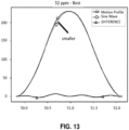
- An approach is like an iterative process in order to get the optimal length of the look-up tables. For example, if the length of the look-up table is bigger than the optimal value, then try to fit the measurement data into a one-cycle sinusoidal curve, it usually fits better on the left side than the right side as shown in FIG. 12 . If the length of the look-up table is smaller than the optimal value, it looks like FIG. 13 .
- a python program has been written to calculate the look-up table and check if the RMSE (Root Mean Square Error) and AMD (Absolute Mean Deviation) of the measurement data meet the specification which means they should be smaller than 2.54 mm (0.1 inch). Also the maximum speed at the midpoint of the track and the speed of the wheels are verified to meet the criteria which means the result should be within 0.305 ⁇ 0.02 m/s (1 ⁇ 0.066 ft/s) and 52 ⁇ 2 ppm.
- RMSE Root Mean Square Error
- AMD Absolute.g., Average Mean Deviation
- a method, according to at least one embodiment, of obtaining sinusoidal motion is represented as a flowchart in FIG. 25 .
- Steps include measurement of motion, for example by the gathering of positional data as a function of time.
- a Fourier Transform or FFT is then performed on the data which may be position, velocity, or acceleration.
- the total harmonic distortion (THD) of the displacement velocity is obtained in reference to the desired fundamental.
- THD total harmonic distortion
- the process continues or recycles until the cycles are finished.
- the desired fundamental frequency in at least one embodiment is 52 RPM (passes per minute).
- the correction vector associated with the FFT can also be injected directly to the motor by way of the proper frequency domain controlling system.
- depth measurement will be performed by a magnetostrictive transducer mounted on the cylinder 222 ( FIG. 3A ) with a magnetic piston. It will read the position of the piston as the wheels track across the sample and use the measured values to interpolate the wheel depth (rut depth) based on a calibration curve.
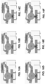
- the calibration curve can be any typical curve fitting, spline or numerical routine such as a fifth-degree polynomial. This example is created from seven data points using a set of six height standards ( FIGS. 16A-16E ) on a base plate mounted in the sample tray.
- the fifth-degree polynomial was chosen because it follows the trend of the data more accurately when extrapolating passed the measurement range and interpolating between the measured data points. There are many kernels in which the data could be fit to; including exponential functions, polynomial, sigmodal, hyperbola, waveform, power, and piecewise to name a few.
- a height standard base plate is secured to the sample tray with two screws and is supported by three ball end set screws to ensure there is no rocking or play due to an uneven surface.
- the three set screws are initially adjusted such that the total height of the base plate plus the first height standard is lower than the maximum rut depth expected.
- Each height standard has three oversized ball bearings pressed into undersized counterbores to ensure there is no rocking or discrepancies in height due to dirt and debris getting under the height standards. After pressing the balls into each height standard, each calibration set will be measured on the CMM to record their final heights.
- the arms 216 are lowered onto each block and the Balluff reading is digitized and recorded in a table next to the corresponding height of the standard block obtained from the CMM measurements.
- the blocks are measured from shortest to tallest and repeated from tallest to shortest.
- the average Balluff value for each block is then used as the final Balluff data to generate the calibration curves. This is done for each arm.
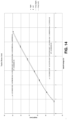
- FIG. 14 shows an example of the calibration curves (here shown in volts instead of counts) obtained for a standard unit.
- a test track of a known radius is used to verify the results of calibration, as well as the indexing locations where height data is recorded. Since the wheel's contact point on the radius varies from the horizontal position of the wheel's axis in a non-linear way (except at the lowest point). Calculations can be made to accommodate for this variation given a known track radius measured on the CMM. Note that the tracks in a particular example have a roundness tolerance of .001".
- This equation can be used to directly compare the measured readings from the track profile to the known curvature of the verification track with compensation for the wheel's offset contact point as a function of wheel center position (x).
- the curvature of the verification track (R) and actual wheel diameter (r) are measured with a CMM and associated with each verification track and WT machine.
- This equation calculates the x location of the first measured data point (y 11 ) to determine the offset necessary to center the measured data on the verification curve. All subsequent data points are taken to be some value such as 0.90 inches from the previous point and are plotted accordingly (see below equation).
- This equation calculates the absolute difference between the measured height at a given location and the known height at that location.
- This equation calculates the root mean square error of the 11 measured data points with respect to the verification track profile.
- Table 2 includes data from an MODOT calibration. Averages were used. Only data after the point where it looks like it has settled was incorporated, sometimes this is after 30 passes.
- the curve to compare the data to for RMSE calculation is the 'CMM' curve that has been compensated for the actual wheel contact position called 'LVDT'.
- LVDT R _ CMM ⁇ Wheel _ r ⁇ SQRT R _ CMM ⁇ 2 ⁇ 2 * R _ CMM * Wheel _ r + Wheel _ r ⁇ 2 ⁇ X ⁇ 2
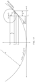
- FIG. 18 is a plot of curvature of rut depth a metal calibration specimen in comparison with a measured LVDT reading.
- the apparatus 100 provides a light curtain 350 at least partially surrounding a perimeter of the sample testing area 112. If the light curtain 350 is interrupted, the apparatus 100 ceases operations to avoid injury or damage.
- the light curtain 350 can be constructed with components made, for example, by Datalogic (SG4-30-045-OO-E) and utilize an array of 24 IR laser beams (950 nm) generated by LEDs to paint an invisible fence between an emitter 352 and receiver 354, the positions of which may be interchanged.
- the beams are ⁇ .44" in diameter and are spaced ⁇ .75" apart.
- the wheel tracker machines have two mirrors 356 housed in adjustable mounts that allow the beams to paint a fence around the testing area.
- These light curtain 350 is insensitive to vibration and takes up very little space, with the emitter column 352, receiver column 354 and mirror columns 356 extending upward from the exterior walls 114 of the cabinet 104 to arrange portions of the light curtain 350 in vertical planes.
- the light curtain 350 has a forward planar portion between the mirror columns 356, and respective left and right planar portions forward of the emitter 352 and receiver 354.
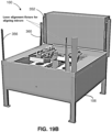
- the light curtain is at least partially deactivated, and alignment fixtures 360 for aligning mirrors 356 are shown.
- the alignment fixtures 360 mount on the frame 106 for aligning the mirrors.
- One fixture has a red laser diode and the other has a reticle at the same height.
- the assembler will mount the diode laser in front of the emitter and the reticle on the beam perpendicular to the first mirror 356. Once the mirror has been adjusted, the reticle is moved to the beam perpendicular to the second mirror 356 and the process is repeated.
- a kit may be provided.
- the Kit may include the motor controller and linear sensors along the rail for measuring the motion, further including the feedback and controls, software, to make the loading wheel sinusoidal in motion.
- the disk shaped sensor that was on the motor is removed and an optical sensor placed on the rail to obtain the roller motion in real time.
- This sensor can be calibrated at the factory using an additional Balluff sensor attached to the rail motion. After the calibration, the optical linear sensor is used and the Balluff may be removed.
- Capacitor-start induction motor Capacitor run motor induction motor
- Resistance split-phase motor induction motor Permanent magnet motor
- DC Motor induction, synchronous, asynchronous, inverter duty motor, polyphase induction motors, Squirrel cage induction motor.
- the apparatus disclosed herein may be provided with the Speed Control of a Three-Phase Asynchronous Motor. It is often desirable to control the motor speed, usually for reasons process control for such variables as flow or pressure. Applications such as fans and pumps often have varying output requirements, and control of the motor speed is more efficient than mechanically limiting the process output with such devices as throttling valves or dampers.
- motor speed control can be used to save energy by reducing wasted energy used to mechanically control the process.
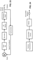
- FIG. 20 is Block Diagram for a Feedback Controller, in which a closed loop control is used.
- a closed-loop motor controller is incorporated for maintaining a desired motor speed under varying load conditions by changing the average voltage applied to the input from the controller.
- the tachometer could be replaced by an optical encoder or Hall-effect type positional or rotary sensor.
- FIGS. 21-24 are schematic representations of methods for motor control according to several embodiments.
- Adjustable-speed drives are a commonly-used AC motor control method. In many commercial and industrial environments these have supplanted other motor speed control methods.
- An adjustable-speed drive works on the principle of varying the frequency to vary the speed of the motor.
- the synchronous speed of a motor is a function of both the system frequency and the number of poles of the motor. By varying the frequency, the motor speed may be varied so long as the motor is equipped to dissipate the heat at reduced speeds. Also due to the high switching frequencies, common-mode noise on the grounding conductors can be an issue when these drives are employed.
- a new means for attaining sinusoidal motion of a wheel tracker is to measure the actual motion, compare this in real time to desired sinusoidal motion, and apply this correction by changing the frequency applied to the input from the controller.
- Many different sensors may be used such as optical, video, magnetostrictive, or Hall Effect sensors.
- a preferred magnetostrictive sensor is the Balluff.
- the amplitude can be measured or calculated since this is a fixed mechanical system. Measured amplitude and period is preferably measured. Comparing or fitting this motion to a sinusoidal motion leads to the desired real time corrections that can be applied to the mechanism thus minimizing the error.
- the motion and reference positions can be determined in the factory and applied instantly as a function of position and time.
- An optical linear sensor attached to the rail or motor (motion point) ca be used to trigger the correction signals at the proper times.
- a single trigger point can start the motor speed or slip correction as determined by a table of motor speeds using a clock signal synchronized with the motor or controller. Multiple trigger positions are also possible.
- the motion of the roller can be stored in memory in communication with the processor, mapped out, and an algorithm to "lead” the response can improve or further reduce the error in motion.
- a learning algorithm incorporated with or without a PID system included in the feedback can be useful.
- the induction motor drive coupled with the mechanical linkages results in a dynamic nonlinear system: hence, using the PID and an artificial neural network (ANN), software, sensors result in a programmable desired motion.
- ANN artificial neural network
- the noise on the line generated by discontinuous switching of frequency may be reduced by low pass filtering the digital inputs (the frequency table or frequency data stream commands) to the AC adjustable drive.
- analog filters can be attached to the power source.
- the mechanical inertia greatly smooths the actual motion as well.
Landscapes
- Physics & Mathematics (AREA)
- General Physics & Mathematics (AREA)
- Health & Medical Sciences (AREA)
- Life Sciences & Earth Sciences (AREA)
- Chemical & Material Sciences (AREA)
- General Health & Medical Sciences (AREA)
- Biochemistry (AREA)
- Analytical Chemistry (AREA)
- Immunology (AREA)
- Pathology (AREA)
- Engineering & Computer Science (AREA)
- Automation & Control Theory (AREA)
- Food Science & Technology (AREA)
- Medicinal Chemistry (AREA)
- Investigating Strength Of Materials By Application Of Mechanical Stress (AREA)
Claims (15)
- Appareil destiné à la réalisation d'essais sur des échantillons de pavage, comprenant :une base (102) ;un plateau d'échantillon de pavage (120) ;un rouleau (202) conçu pour une translation par rapport au plateau d'échantillon de pavage (120) et conférant des forces de compression à un échantillon (124) porté par le plateau d'échantillon ;un bras avant (216) conçu pour déplacer le rouleau (202) d'une position rangée (P1), dans laquelle un utilisateur se voit offert un accès libre à l'échantillon (124), jusqu'à une position d'utilisation (P2) où le rouleau entre en contact avec l'échantillon (124) ;un actionneur de levage motorisé (220) au moyen duquel le bras avant (216) peut être levé et abaissé, par le retrait et l'extension de l'actionneur de levage motorisé (220), ledit bras avant (216) étant déplacé vers sa configuration rangée (P1) et sa configuration d'utilisation (P2) respectivement, l'actionneur de levage motorisé (220) comprenant un cylindre (222) comportant une tige de piston (224) à l'intérieur de celui-ci destinée à fournir des forces de pression au bras avant (216) pour déplacer le rouleau (202) de la position rangée (P1) vers la position d'utilisation (P2), une profondeur de déplacement du bras avant étant limitée par l'échantillon (124), moyennant quoi, tandis que l'échantillon est comprimé, ladite profondeur de déplacement augmente ;un dispositif de mesure (230) en communication avec le cylindre (222) pour déterminer une quantité de déplacement du bras avant (216) afin de déterminer ainsi une quantité de compression de l'échantillon (124) ; etun système de commande (400) conçu pour modifier une vitesse du bras avant (216) afin de régler un profil de mouvement du rouleau (202) pour correspondre à un profil prédéterminé.
- Appareil selon la revendication 1, ladite base définissant une zone d'essai d'échantillon (112) destinée à recevoir le plateau d'échantillon de pavage (120).
- Appareil selon la revendication 2, ladite zone d'essai d'échantillon (112) définissant un bain d'eau en vue de l'immersion de l'échantillon (124).
- Appareil selon la revendication 1, ledit bras avant (216) définissant un pivot autour du plateau d'échantillon de pavage et de la base, et ledit cylindre (222) s'étendant entre les points de pivot respectifs entre le plateau d'échantillon et la base.
- Appareil selon la revendication 1, ledit dispositif de mesure (230) étant un capteur à effet hall conçu pour déterminer une position de la tige de piston (224) à l'intérieur du cylindre (222).
- Appareil selon la revendication 1, comprenant en outre un transducteur monté (620) qui est couplé magnétiquement à l'appareil pour détecter l'emplacement de la roue.
- Appareil selon la revendication 1, comprenant en outre un réseau de lumières conçu pour envoyer un signal lumineux autour d'une périphérie de l'appareil, lorsque le signal lumineux est interrompu, ledit système de commande ordonnant à l'appareil de cesser ses opérations.
- Appareil selon la revendication 1, ledit bras avant (216) étant conçu pour recevoir un ou plusieurs poids en vue de l'ajout de forces de compression au rouleau (202).
- Appareil selon la revendication 1, des forces de compression étant sélectivement fournies par le cylindre (222), qui peut être mis en prise et séparé.
- Appareil selon la revendication 1, communiquant en outre avec un dispositif informatique conçu pour recevoir une entrée en provenance d'un opérateur pour commander l'appareil.
- Appareil selon la revendication 1, ledit cylindre (222) limitant une vitesse de descente du bras avant (216) de la position rangée (P1) à la position d'utilisation (P2), moyennant quoi l'impact du rouleau (202) sur l'échantillon (124) est amorti lorsqu'il atteint la position d'utilisation.
- Appareil selon la revendication 1, comprenant en outre une poutre s'étendant latéralement (210) et un bras arrière (214) relié rigidement à la poutre (210) et s'étendant vers l'avant à partir de celle-ci, le bras avant (216) s'articulant et s'étendant selon une disposition variable, à partir du bras arrière (214).
- Appareil selon la revendication 12, ledit mouvement de translation de la poutre (210) par rapport au plateau d'échantillon (120) produisant le mouvement d'un support de rouleau (204, 206), qui comprend le rouleau (202), par rapport au plateau d'échantillon (120).
- Appareil selon la revendication 12, ledit bras avant (216) pivotant par rotation partielle autour d'un axe d'articulation (218) au niveau de la jonction du bras arrière (214) et du bras avant (216).
- Appareil selon la revendication 14, ledit actionneur de levage motorisé (220) étant relié de manière articulée au niveau de son extrémité arrière à la poutre (210) décalée du bras arrière (214), et au niveau de son extrémité avant au bras avant (216) décalée de l'axe d'articulation (218).
Applications Claiming Priority (3)
| Application Number | Priority Date | Filing Date | Title |
|---|---|---|---|
| US201762443719P | 2017-01-08 | 2017-01-08 | |
| US201762548360P | 2017-08-21 | 2017-08-21 | |
| PCT/US2018/012843 WO2018129483A1 (fr) | 2017-01-08 | 2018-01-08 | Appareil, procédé et système associé permettant de tester un échantillon de matériau de chaussée |
Publications (3)
| Publication Number | Publication Date |
|---|---|
| EP3566039A1 EP3566039A1 (fr) | 2019-11-13 |
| EP3566039A4 EP3566039A4 (fr) | 2020-07-15 |
| EP3566039B1 true EP3566039B1 (fr) | 2023-06-07 |
Family
ID=62790924
Family Applications (1)
| Application Number | Title | Priority Date | Filing Date |
|---|---|---|---|
| EP18736647.1A Active EP3566039B1 (fr) | 2017-01-08 | 2018-01-08 | Appareil permettant de tester un échantillon de matériau de chaussée |
Country Status (3)
| Country | Link |
|---|---|
| US (3) | US11307124B2 (fr) |
| EP (1) | EP3566039B1 (fr) |
| WO (1) | WO2018129483A1 (fr) |
Families Citing this family (10)
| Publication number | Priority date | Publication date | Assignee | Title |
|---|---|---|---|---|
| CN109946164B (zh) * | 2019-03-11 | 2020-07-24 | 中国矿业大学(北京) | 一种模拟煤矿采场煤岩灾变的实验平台及实验方法 |
| CN113358473B (zh) * | 2021-06-21 | 2023-10-27 | 重庆交通大学 | 一种便于直接野外工作的岩石断裂韧度专用试验装置 |
| CN113740191B (zh) * | 2021-08-31 | 2024-07-23 | 浙江兄弟路标涂料有限公司 | 一种检测路面标线反光的喷淋系统 |
| CN114459914B (zh) * | 2022-02-11 | 2024-09-03 | 大连交通大学 | 一种基于数字图像技术的钢桥变形测试及分析装置 |
| CN114705571B (zh) * | 2022-06-07 | 2022-08-26 | 常州凯度机电有限公司 | 一种用于汽轮机叶片耐冲击力的测试装置 |
| US12366834B2 (en) * | 2022-07-05 | 2025-07-22 | Mitsubishi Electric Research Laboratories, Inc. | Device for controlling a system with polynomial dynamics |
| CN115165594B (zh) * | 2022-07-18 | 2023-03-24 | 山东金博电动车有限公司 | 用于电动车轮毂承压测试台 |
| CN115308065B (zh) * | 2022-08-18 | 2023-09-12 | 浙江天女集团制漆有限公司 | 一种新型丙烯酸酯聚氨酯涂层耐磨性检测设备 |
| CN118209425B (zh) * | 2024-02-01 | 2024-11-01 | 泰山石膏(东营)有限公司 | 一种纸面石膏板生产用承压检测设备 |
| CN120385567B (zh) * | 2025-05-12 | 2026-03-06 | 江苏晟宇地板有限公司 | 一种基于力学传感器的环保抗静电实木复合地板载荷检测装置 |
Family Cites Families (23)
| Publication number | Priority date | Publication date | Assignee | Title |
|---|---|---|---|---|
| US3888108A (en) * | 1973-08-02 | 1975-06-10 | Frank W Brands | Pavement testing apparatus |
| US3997277A (en) * | 1975-06-13 | 1976-12-14 | Cmi Corporation | Material transfer mechanism |
| CA1195141A (fr) * | 1982-05-06 | 1985-10-15 | Stephen P. Scrivener | Dispositif d'epreuve pour chaussees |
| US5036709A (en) * | 1989-06-06 | 1991-08-06 | Mcrae John L | Paving materials testing machine |
| US5356238A (en) * | 1993-03-10 | 1994-10-18 | Cedarapids, Inc. | Paver with material supply and mat grade and slope quality control apparatus and method |
| US5969261A (en) * | 1996-01-11 | 1999-10-19 | Troxler Electronics Laboratories, Inc. | Apparatus and method for measuring rutting susceptibility |
| US5659140A (en) * | 1996-08-13 | 1997-08-19 | Pavement Technology, Inc. | Testing machine for pavement samples |
| US6102614A (en) * | 1998-07-08 | 2000-08-15 | The Nippon Road Company Limited | Pavement for automobile test course |
| US5987961A (en) * | 1998-10-22 | 1999-11-23 | Harris; Jeffrey A. | Apparatus and method for testing paving |
| EP1373666B1 (fr) | 2001-03-15 | 2005-05-04 | Sotefin S.A. | Chariot pour le transfert horizontal de vehicules motorises dans des parkings automatiques |
| US7252012B2 (en) * | 2002-08-23 | 2007-08-07 | Ohio University | Device and method for testing paving materials |
| TW549441U (en) * | 2002-10-29 | 2003-08-21 | De-Shian Shen | Testing apparatus of direct shear force |
| US9587938B2 (en) * | 2003-06-17 | 2017-03-07 | Troxler Electronic Laboratories, Inc. | Method and apparatus for determining a characteristic of a construction material |
| FR2882823B1 (fr) * | 2005-03-04 | 2007-05-11 | Vallourec Mannesmann Oil Gas F | Installation et procede de sollicitation mecanique d'echantillon au moyen d'un packer |
| RU2284423C1 (ru) * | 2005-05-05 | 2006-09-27 | ОАО "Пневмостроймашина" | Аксиально-поршневая машина с преобразователем хода поршня управления |
| US9234825B2 (en) | 2011-03-29 | 2016-01-12 | University Of Tennessee Research Foundation | Method and apparatus for fatigue and viscoelastic property testing of asphalt mixtures using a loaded wheel tester |
| US20140151460A1 (en) * | 2012-12-02 | 2014-06-05 | General Electric Company | System and method for maintaining sensor performance |
| US9964471B2 (en) | 2014-04-14 | 2018-05-08 | Instrotek, Inc. | Wheel-tracking devices and related systems and methods |
| CA2948912C (fr) | 2014-05-13 | 2022-01-04 | Giatec Scientific Ltd. | Procedes et systemes electriques pour essais sur beton |
| US11927965B2 (en) * | 2016-02-29 | 2024-03-12 | AI Incorporated | Obstacle recognition method for autonomous robots |
| EP3479095B1 (fr) * | 2016-06-30 | 2021-02-24 | The University Of Canterbury | Appareil et procédé de test d'un échantillon de chaussée |
| WO2018209381A1 (fr) * | 2017-05-16 | 2018-11-22 | Fct Actech Pty Ltd | Procédé et appareil pour l'analyse de matières particulaires |
| CN115244872B (zh) * | 2020-03-02 | 2024-06-04 | 日本电气株式会社 | 海底光通信系统和通信方法 |
-
2018
- 2018-01-08 EP EP18736647.1A patent/EP3566039B1/fr active Active
- 2018-01-08 WO PCT/US2018/012843 patent/WO2018129483A1/fr not_active Ceased
-
2019
- 2019-07-08 US US16/505,210 patent/US11307124B2/en active Active
-
2022
- 2022-04-18 US US17/722,887 patent/US11959889B2/en active Active
-
2024
- 2024-04-15 US US18/635,587 patent/US20240264055A1/en active Pending
Also Published As
| Publication number | Publication date |
|---|---|
| US11307124B2 (en) | 2022-04-19 |
| WO2018129483A1 (fr) | 2018-07-12 |
| EP3566039A1 (fr) | 2019-11-13 |
| US20190331571A1 (en) | 2019-10-31 |
| US20220244154A1 (en) | 2022-08-04 |
| US20240264055A1 (en) | 2024-08-08 |
| EP3566039A4 (fr) | 2020-07-15 |
| US11959889B2 (en) | 2024-04-16 |
Similar Documents
| Publication | Publication Date | Title |
|---|---|---|
| EP3566039B1 (fr) | Appareil permettant de tester un échantillon de matériau de chaussée | |
| CN112587246B (zh) | 自平衡调节支撑平台、机器人及自平衡调节方法 | |
| CN107727412B (zh) | 一种参数化可调试尾门台架 | |
| BR102015000145B1 (pt) | Aparelho e método de alinhamento | |
| CN205449514U (zh) | 一种汽车踏板检测装置 | |
| CN106644046A (zh) | 一种声强全自动测量支架及其测量方法 | |
| CN205403838U (zh) | 一种多功能机器人关节性能测试系统 | |
| CN106033221A (zh) | 一种振动式传感器标定系统及其角度调节装置和方法 | |
| KR102200118B1 (ko) | 다축 동적 하중 시험 장치 | |
| CN110044745B (zh) | 可施加复杂耦合作用力的疲劳试验机及其控制电路 | |
| CN107063118A (zh) | 自动测量轴类零件外表面圆柱度的装置 | |
| CN208173051U (zh) | 一种bms实训用三维旋转支架 | |
| CN207610864U (zh) | 车门铰链角度调节装置 | |
| KR100774917B1 (ko) | 슬라이딩포스 측정시스템 및 측정방법 | |
| CN207408113U (zh) | 参数化可调试尾门台架 | |
| Wischnewski et al. | Piezoelectric motor operated both in resonance and DC modes | |
| CN108827131B (zh) | 一种变形量测试装置 | |
| CN208026241U (zh) | 沉积体高度测量器及沉积体高度测量装置 | |
| CN215180201U (zh) | 一种灌浆密实度检测装置 | |
| CN117549287A (zh) | 一种无传感的柔索驱动机构位置补偿方法 | |
| CN120102068B (zh) | 一种振动测试设备及测试方法 | |
| EP4238848A1 (fr) | Système pour stimuler les conditions de travail des câbles de connexion entre deux wagons successifs d'un rateau de chemin de fer | |
| KR100955508B1 (ko) | 공시체 소성변형 시험장치 | |
| CN219689235U (zh) | 一种钢结构安装辅助装置 | |
| CN106272439B (zh) | 一种仪表盘定位方法及仪表盘机械手 |
Legal Events
| Date | Code | Title | Description |
|---|---|---|---|
| STAA | Information on the status of an ep patent application or granted ep patent |
Free format text: STATUS: THE INTERNATIONAL PUBLICATION HAS BEEN MADE |
|
| PUAI | Public reference made under article 153(3) epc to a published international application that has entered the european phase |
Free format text: ORIGINAL CODE: 0009012 |
|
| STAA | Information on the status of an ep patent application or granted ep patent |
Free format text: STATUS: REQUEST FOR EXAMINATION WAS MADE |
|
| 17P | Request for examination filed |
Effective date: 20190806 |
|
| AK | Designated contracting states |
Kind code of ref document: A1 Designated state(s): AL AT BE BG CH CY CZ DE DK EE ES FI FR GB GR HR HU IE IS IT LI LT LU LV MC MK MT NL NO PL PT RO RS SE SI SK SM TR |
|
| AX | Request for extension of the european patent |
Extension state: BA ME |
|
| DAV | Request for validation of the european patent (deleted) | ||
| DAX | Request for extension of the european patent (deleted) | ||
| A4 | Supplementary search report drawn up and despatched |
Effective date: 20200612 |
|
| RIC1 | Information provided on ipc code assigned before grant |
Ipc: G01N 3/56 20060101ALI20200606BHEP Ipc: G01N 3/00 20060101AFI20200606BHEP Ipc: G01N 33/42 20060101ALI20200606BHEP |
|
| STAA | Information on the status of an ep patent application or granted ep patent |
Free format text: STATUS: EXAMINATION IS IN PROGRESS |
|
| 17Q | First examination report despatched |
Effective date: 20210902 |
|
| GRAP | Despatch of communication of intention to grant a patent |
Free format text: ORIGINAL CODE: EPIDOSNIGR1 |
|
| STAA | Information on the status of an ep patent application or granted ep patent |
Free format text: STATUS: GRANT OF PATENT IS INTENDED |
|
| INTG | Intention to grant announced |
Effective date: 20221221 |
|
| GRAS | Grant fee paid |
Free format text: ORIGINAL CODE: EPIDOSNIGR3 |
|
| GRAA | (expected) grant |
Free format text: ORIGINAL CODE: 0009210 |
|
| STAA | Information on the status of an ep patent application or granted ep patent |
Free format text: STATUS: THE PATENT HAS BEEN GRANTED |
|
| AK | Designated contracting states |
Kind code of ref document: B1 Designated state(s): AL AT BE BG CH CY CZ DE DK EE ES FI FR GB GR HR HU IE IS IT LI LT LU LV MC MK MT NL NO PL PT RO RS SE SI SK SM TR |
|
| RAP3 | Party data changed (applicant data changed or rights of an application transferred) |
Owner name: TROXLER ELECTRONIC LABORATORIES, INC. |
|
| REG | Reference to a national code |
Ref country code: GB Ref legal event code: FG4D |
|
| REG | Reference to a national code |
Ref country code: CH Ref legal event code: EP Ref country code: AT Ref legal event code: REF Ref document number: 1576482 Country of ref document: AT Kind code of ref document: T Effective date: 20230615 |
|
| REG | Reference to a national code |
Ref country code: DE Ref legal event code: R096 Ref document number: 602018051041 Country of ref document: DE |
|
| REG | Reference to a national code |
Ref country code: LT Ref legal event code: MG9D |
|
| P01 | Opt-out of the competence of the unified patent court (upc) registered |
Effective date: 20230828 |
|
| REG | Reference to a national code |
Ref country code: NL Ref legal event code: MP Effective date: 20230607 |
|
| PG25 | Lapsed in a contracting state [announced via postgrant information from national office to epo] |
Ref country code: SE Free format text: LAPSE BECAUSE OF FAILURE TO SUBMIT A TRANSLATION OF THE DESCRIPTION OR TO PAY THE FEE WITHIN THE PRESCRIBED TIME-LIMIT Effective date: 20230607 Ref country code: NO Free format text: LAPSE BECAUSE OF FAILURE TO SUBMIT A TRANSLATION OF THE DESCRIPTION OR TO PAY THE FEE WITHIN THE PRESCRIBED TIME-LIMIT Effective date: 20230907 Ref country code: ES Free format text: LAPSE BECAUSE OF FAILURE TO SUBMIT A TRANSLATION OF THE DESCRIPTION OR TO PAY THE FEE WITHIN THE PRESCRIBED TIME-LIMIT Effective date: 20230607 |
|
| REG | Reference to a national code |
Ref country code: AT Ref legal event code: MK05 Ref document number: 1576482 Country of ref document: AT Kind code of ref document: T Effective date: 20230607 |
|
| PG25 | Lapsed in a contracting state [announced via postgrant information from national office to epo] |
Ref country code: RS Free format text: LAPSE BECAUSE OF FAILURE TO SUBMIT A TRANSLATION OF THE DESCRIPTION OR TO PAY THE FEE WITHIN THE PRESCRIBED TIME-LIMIT Effective date: 20230607 Ref country code: NL Free format text: LAPSE BECAUSE OF FAILURE TO SUBMIT A TRANSLATION OF THE DESCRIPTION OR TO PAY THE FEE WITHIN THE PRESCRIBED TIME-LIMIT Effective date: 20230607 Ref country code: LV Free format text: LAPSE BECAUSE OF FAILURE TO SUBMIT A TRANSLATION OF THE DESCRIPTION OR TO PAY THE FEE WITHIN THE PRESCRIBED TIME-LIMIT Effective date: 20230607 Ref country code: LT Free format text: LAPSE BECAUSE OF FAILURE TO SUBMIT A TRANSLATION OF THE DESCRIPTION OR TO PAY THE FEE WITHIN THE PRESCRIBED TIME-LIMIT Effective date: 20230607 Ref country code: HR Free format text: LAPSE BECAUSE OF FAILURE TO SUBMIT A TRANSLATION OF THE DESCRIPTION OR TO PAY THE FEE WITHIN THE PRESCRIBED TIME-LIMIT Effective date: 20230607 Ref country code: GR Free format text: LAPSE BECAUSE OF FAILURE TO SUBMIT A TRANSLATION OF THE DESCRIPTION OR TO PAY THE FEE WITHIN THE PRESCRIBED TIME-LIMIT Effective date: 20230908 |
|
| PG25 | Lapsed in a contracting state [announced via postgrant information from national office to epo] |
Ref country code: FI Free format text: LAPSE BECAUSE OF FAILURE TO SUBMIT A TRANSLATION OF THE DESCRIPTION OR TO PAY THE FEE WITHIN THE PRESCRIBED TIME-LIMIT Effective date: 20230607 |
|
| PG25 | Lapsed in a contracting state [announced via postgrant information from national office to epo] |
Ref country code: SK Free format text: LAPSE BECAUSE OF FAILURE TO SUBMIT A TRANSLATION OF THE DESCRIPTION OR TO PAY THE FEE WITHIN THE PRESCRIBED TIME-LIMIT Effective date: 20230607 |
|
| PG25 | Lapsed in a contracting state [announced via postgrant information from national office to epo] |
Ref country code: IS Free format text: LAPSE BECAUSE OF FAILURE TO SUBMIT A TRANSLATION OF THE DESCRIPTION OR TO PAY THE FEE WITHIN THE PRESCRIBED TIME-LIMIT Effective date: 20231007 |
|
| PG25 | Lapsed in a contracting state [announced via postgrant information from national office to epo] |
Ref country code: SM Free format text: LAPSE BECAUSE OF FAILURE TO SUBMIT A TRANSLATION OF THE DESCRIPTION OR TO PAY THE FEE WITHIN THE PRESCRIBED TIME-LIMIT Effective date: 20230607 Ref country code: SK Free format text: LAPSE BECAUSE OF FAILURE TO SUBMIT A TRANSLATION OF THE DESCRIPTION OR TO PAY THE FEE WITHIN THE PRESCRIBED TIME-LIMIT Effective date: 20230607 Ref country code: RO Free format text: LAPSE BECAUSE OF FAILURE TO SUBMIT A TRANSLATION OF THE DESCRIPTION OR TO PAY THE FEE WITHIN THE PRESCRIBED TIME-LIMIT Effective date: 20230607 Ref country code: PT Free format text: LAPSE BECAUSE OF FAILURE TO SUBMIT A TRANSLATION OF THE DESCRIPTION OR TO PAY THE FEE WITHIN THE PRESCRIBED TIME-LIMIT Effective date: 20231009 Ref country code: IS Free format text: LAPSE BECAUSE OF FAILURE TO SUBMIT A TRANSLATION OF THE DESCRIPTION OR TO PAY THE FEE WITHIN THE PRESCRIBED TIME-LIMIT Effective date: 20231007 Ref country code: EE Free format text: LAPSE BECAUSE OF FAILURE TO SUBMIT A TRANSLATION OF THE DESCRIPTION OR TO PAY THE FEE WITHIN THE PRESCRIBED TIME-LIMIT Effective date: 20230607 Ref country code: CZ Free format text: LAPSE BECAUSE OF FAILURE TO SUBMIT A TRANSLATION OF THE DESCRIPTION OR TO PAY THE FEE WITHIN THE PRESCRIBED TIME-LIMIT Effective date: 20230607 Ref country code: AT Free format text: LAPSE BECAUSE OF FAILURE TO SUBMIT A TRANSLATION OF THE DESCRIPTION OR TO PAY THE FEE WITHIN THE PRESCRIBED TIME-LIMIT Effective date: 20230607 |
|
| PG25 | Lapsed in a contracting state [announced via postgrant information from national office to epo] |
Ref country code: PL Free format text: LAPSE BECAUSE OF FAILURE TO SUBMIT A TRANSLATION OF THE DESCRIPTION OR TO PAY THE FEE WITHIN THE PRESCRIBED TIME-LIMIT Effective date: 20230607 |
|
| REG | Reference to a national code |
Ref country code: DE Ref legal event code: R097 Ref document number: 602018051041 Country of ref document: DE |
|
| PLBE | No opposition filed within time limit |
Free format text: ORIGINAL CODE: 0009261 |
|
| STAA | Information on the status of an ep patent application or granted ep patent |
Free format text: STATUS: NO OPPOSITION FILED WITHIN TIME LIMIT |
|
| PG25 | Lapsed in a contracting state [announced via postgrant information from national office to epo] |
Ref country code: DK Free format text: LAPSE BECAUSE OF FAILURE TO SUBMIT A TRANSLATION OF THE DESCRIPTION OR TO PAY THE FEE WITHIN THE PRESCRIBED TIME-LIMIT Effective date: 20230607 |
|
| PG25 | Lapsed in a contracting state [announced via postgrant information from national office to epo] |
Ref country code: SI Free format text: LAPSE BECAUSE OF FAILURE TO SUBMIT A TRANSLATION OF THE DESCRIPTION OR TO PAY THE FEE WITHIN THE PRESCRIBED TIME-LIMIT Effective date: 20230607 |
|
| 26N | No opposition filed |
Effective date: 20240308 |
|
| PG25 | Lapsed in a contracting state [announced via postgrant information from national office to epo] |
Ref country code: SI Free format text: LAPSE BECAUSE OF FAILURE TO SUBMIT A TRANSLATION OF THE DESCRIPTION OR TO PAY THE FEE WITHIN THE PRESCRIBED TIME-LIMIT Effective date: 20230607 |
|
| PG25 | Lapsed in a contracting state [announced via postgrant information from national office to epo] |
Ref country code: MC Free format text: LAPSE BECAUSE OF FAILURE TO SUBMIT A TRANSLATION OF THE DESCRIPTION OR TO PAY THE FEE WITHIN THE PRESCRIBED TIME-LIMIT Effective date: 20230607 |
|
| PG25 | Lapsed in a contracting state [announced via postgrant information from national office to epo] |
Ref country code: MC Free format text: LAPSE BECAUSE OF FAILURE TO SUBMIT A TRANSLATION OF THE DESCRIPTION OR TO PAY THE FEE WITHIN THE PRESCRIBED TIME-LIMIT Effective date: 20230607 |
|
| REG | Reference to a national code |
Ref country code: CH Ref legal event code: PL |
|
| PG25 | Lapsed in a contracting state [announced via postgrant information from national office to epo] |
Ref country code: LU Free format text: LAPSE BECAUSE OF NON-PAYMENT OF DUE FEES Effective date: 20240108 |
|
| PG25 | Lapsed in a contracting state [announced via postgrant information from national office to epo] |
Ref country code: LU Free format text: LAPSE BECAUSE OF NON-PAYMENT OF DUE FEES Effective date: 20240108 |
|
| PG25 | Lapsed in a contracting state [announced via postgrant information from national office to epo] |
Ref country code: BE Free format text: LAPSE BECAUSE OF NON-PAYMENT OF DUE FEES Effective date: 20240131 |
|
| PG25 | Lapsed in a contracting state [announced via postgrant information from national office to epo] |
Ref country code: CH Free format text: LAPSE BECAUSE OF NON-PAYMENT OF DUE FEES Effective date: 20240131 |
|
| PG25 | Lapsed in a contracting state [announced via postgrant information from national office to epo] |
Ref country code: CH Free format text: LAPSE BECAUSE OF NON-PAYMENT OF DUE FEES Effective date: 20240131 Ref country code: BE Free format text: LAPSE BECAUSE OF NON-PAYMENT OF DUE FEES Effective date: 20240131 |
|
| REG | Reference to a national code |
Ref country code: BE Ref legal event code: MM Effective date: 20240131 |
|
| PG25 | Lapsed in a contracting state [announced via postgrant information from national office to epo] |
Ref country code: BG Free format text: LAPSE BECAUSE OF FAILURE TO SUBMIT A TRANSLATION OF THE DESCRIPTION OR TO PAY THE FEE WITHIN THE PRESCRIBED TIME-LIMIT Effective date: 20230607 |
|
| PG25 | Lapsed in a contracting state [announced via postgrant information from national office to epo] |
Ref country code: BG Free format text: LAPSE BECAUSE OF FAILURE TO SUBMIT A TRANSLATION OF THE DESCRIPTION OR TO PAY THE FEE WITHIN THE PRESCRIBED TIME-LIMIT Effective date: 20230607 |
|
| PG25 | Lapsed in a contracting state [announced via postgrant information from national office to epo] |
Ref country code: IE Free format text: LAPSE BECAUSE OF NON-PAYMENT OF DUE FEES Effective date: 20240108 |
|
| PG25 | Lapsed in a contracting state [announced via postgrant information from national office to epo] |
Ref country code: IE Free format text: LAPSE BECAUSE OF NON-PAYMENT OF DUE FEES Effective date: 20240108 |
|
| PG25 | Lapsed in a contracting state [announced via postgrant information from national office to epo] |
Ref country code: CY Free format text: LAPSE BECAUSE OF FAILURE TO SUBMIT A TRANSLATION OF THE DESCRIPTION OR TO PAY THE FEE WITHIN THE PRESCRIBED TIME-LIMIT; INVALID AB INITIO Effective date: 20180108 |
|
| PG25 | Lapsed in a contracting state [announced via postgrant information from national office to epo] |
Ref country code: HU Free format text: LAPSE BECAUSE OF FAILURE TO SUBMIT A TRANSLATION OF THE DESCRIPTION OR TO PAY THE FEE WITHIN THE PRESCRIBED TIME-LIMIT; INVALID AB INITIO Effective date: 20180108 |
|
| PG25 | Lapsed in a contracting state [announced via postgrant information from national office to epo] |
Ref country code: TR Free format text: LAPSE BECAUSE OF FAILURE TO SUBMIT A TRANSLATION OF THE DESCRIPTION OR TO PAY THE FEE WITHIN THE PRESCRIBED TIME-LIMIT Effective date: 20230607 |
|
| PGFP | Annual fee paid to national office [announced via postgrant information from national office to epo] |
Ref country code: GB Payment date: 20260127 Year of fee payment: 9 |
|
| PGFP | Annual fee paid to national office [announced via postgrant information from national office to epo] |
Ref country code: DE Payment date: 20260128 Year of fee payment: 9 |
|
| PGFP | Annual fee paid to national office [announced via postgrant information from national office to epo] |
Ref country code: IT Payment date: 20260121 Year of fee payment: 9 |
|
| PGFP | Annual fee paid to national office [announced via postgrant information from national office to epo] |
Ref country code: FR Payment date: 20260126 Year of fee payment: 9 |