EP3566362B1 - Motifs de signal de référence - Google Patents
Motifs de signal de référence Download PDFInfo
- Publication number
- EP3566362B1 EP3566362B1 EP17700189.8A EP17700189A EP3566362B1 EP 3566362 B1 EP3566362 B1 EP 3566362B1 EP 17700189 A EP17700189 A EP 17700189A EP 3566362 B1 EP3566362 B1 EP 3566362B1
- Authority
- EP
- European Patent Office
- Prior art keywords
- reference signal
- user equipment
- signal pattern
- functional
- pattern
- Prior art date
- Legal status (The legal status is an assumption and is not a legal conclusion. Google has not performed a legal analysis and makes no representation as to the accuracy of the status listed.)
- Active
Links
Images




Classifications
-
- H—ELECTRICITY
- H04—ELECTRIC COMMUNICATION TECHNIQUE
- H04L—TRANSMISSION OF DIGITAL INFORMATION, e.g. TELEGRAPHIC COMMUNICATION
- H04L5/00—Arrangements affording multiple use of the transmission path
- H04L5/003—Arrangements for allocating sub-channels of the transmission path
- H04L5/0048—Allocation of pilot signals, i.e. of signals known to the receiver
- H04L5/0051—Allocation of pilot signals, i.e. of signals known to the receiver of dedicated pilots, i.e. pilots destined for a single user or terminal
-
- H—ELECTRICITY
- H04—ELECTRIC COMMUNICATION TECHNIQUE
- H04B—TRANSMISSION
- H04B7/00—Radio transmission systems, i.e. using radiation field
- H04B7/02—Diversity systems; Multi-antenna system, i.e. transmission or reception using multiple antennas
- H04B7/04—Diversity systems; Multi-antenna system, i.e. transmission or reception using multiple antennas using two or more spaced independent antennas
- H04B7/08—Diversity systems; Multi-antenna system, i.e. transmission or reception using multiple antennas using two or more spaced independent antennas at the receiving station
- H04B7/0868—Hybrid systems, i.e. switching and combining
- H04B7/088—Hybrid systems, i.e. switching and combining using beam selection
-
- H—ELECTRICITY
- H04—ELECTRIC COMMUNICATION TECHNIQUE
- H04L—TRANSMISSION OF DIGITAL INFORMATION, e.g. TELEGRAPHIC COMMUNICATION
- H04L27/00—Modulated-carrier systems
- H04L27/26—Systems using multi-frequency codes
- H04L27/2601—Multicarrier modulation systems
- H04L27/2602—Signal structure
- H04L27/261—Details of reference signals
- H04L27/2613—Structure of the reference signals
-
- H—ELECTRICITY
- H04—ELECTRIC COMMUNICATION TECHNIQUE
- H04L—TRANSMISSION OF DIGITAL INFORMATION, e.g. TELEGRAPHIC COMMUNICATION
- H04L5/00—Arrangements affording multiple use of the transmission path
- H04L5/003—Arrangements for allocating sub-channels of the transmission path
- H04L5/0048—Allocation of pilot signals, i.e. of signals known to the receiver
-
- H—ELECTRICITY
- H04—ELECTRIC COMMUNICATION TECHNIQUE
- H04L—TRANSMISSION OF DIGITAL INFORMATION, e.g. TELEGRAPHIC COMMUNICATION
- H04L5/00—Arrangements affording multiple use of the transmission path
- H04L5/003—Arrangements for allocating sub-channels of the transmission path
- H04L5/0048—Allocation of pilot signals, i.e. of signals known to the receiver
- H04L5/005—Allocation of pilot signals, i.e. of signals known to the receiver of common pilots, i.e. pilots destined for multiple users or terminals
-
- H—ELECTRICITY
- H04—ELECTRIC COMMUNICATION TECHNIQUE
- H04W—WIRELESS COMMUNICATION NETWORKS
- H04W72/00—Local resource management
- H04W72/20—Control channels or signalling for resource management
- H04W72/23—Control channels or signalling for resource management in the downlink direction of a wireless link, i.e. towards a terminal
-
- H—ELECTRICITY
- H04—ELECTRIC COMMUNICATION TECHNIQUE
- H04B—TRANSMISSION
- H04B7/00—Radio transmission systems, i.e. using radiation field
- H04B7/02—Diversity systems; Multi-antenna system, i.e. transmission or reception using multiple antennas
- H04B7/04—Diversity systems; Multi-antenna system, i.e. transmission or reception using multiple antennas using two or more spaced independent antennas
- H04B7/06—Diversity systems; Multi-antenna system, i.e. transmission or reception using multiple antennas using two or more spaced independent antennas at the transmitting station
-
- H—ELECTRICITY
- H04—ELECTRIC COMMUNICATION TECHNIQUE
- H04B—TRANSMISSION
- H04B7/00—Radio transmission systems, i.e. using radiation field
- H04B7/02—Diversity systems; Multi-antenna system, i.e. transmission or reception using multiple antennas
- H04B7/04—Diversity systems; Multi-antenna system, i.e. transmission or reception using multiple antennas using two or more spaced independent antennas
- H04B7/06—Diversity systems; Multi-antenna system, i.e. transmission or reception using multiple antennas using two or more spaced independent antennas at the transmitting station
- H04B7/0613—Diversity systems; Multi-antenna system, i.e. transmission or reception using multiple antennas using two or more spaced independent antennas at the transmitting station using simultaneous transmission
- H04B7/0615—Diversity systems; Multi-antenna system, i.e. transmission or reception using multiple antennas using two or more spaced independent antennas at the transmitting station using simultaneous transmission of weighted versions of same signal
- H04B7/0617—Diversity systems; Multi-antenna system, i.e. transmission or reception using multiple antennas using two or more spaced independent antennas at the transmitting station using simultaneous transmission of weighted versions of same signal for beam forming
-
- H—ELECTRICITY
- H04—ELECTRIC COMMUNICATION TECHNIQUE
- H04L—TRANSMISSION OF DIGITAL INFORMATION, e.g. TELEGRAPHIC COMMUNICATION
- H04L5/00—Arrangements affording multiple use of the transmission path
- H04L5/0001—Arrangements for dividing the transmission path
- H04L5/0003—Two-dimensional division
- H04L5/0005—Time-frequency
- H04L5/0007—Time-frequency the frequencies being orthogonal, e.g. OFDM(A) or DMT
-
- H—ELECTRICITY
- H04—ELECTRIC COMMUNICATION TECHNIQUE
- H04L—TRANSMISSION OF DIGITAL INFORMATION, e.g. TELEGRAPHIC COMMUNICATION
- H04L5/00—Arrangements affording multiple use of the transmission path
- H04L5/003—Arrangements for allocating sub-channels of the transmission path
- H04L5/0058—Allocation criteria
- H04L5/0073—Allocation arrangements that take into account other cell interferences
-
- H—ELECTRICITY
- H04—ELECTRIC COMMUNICATION TECHNIQUE
- H04L—TRANSMISSION OF DIGITAL INFORMATION, e.g. TELEGRAPHIC COMMUNICATION
- H04L5/00—Arrangements affording multiple use of the transmission path
- H04L5/14—Two-way operation using the same type of signal, i.e. duplex
- H04L5/1469—Two-way operation using the same type of signal, i.e. duplex using time-sharing
Definitions
- communication systems may benefit from improved performance.
- communication systems may benefit from a multi-functional reference signal that allows for harmonization of a plurality of different reference signal patterns.
- EP 2,874,454 A1 relates to an LTE-based wireless communication system in which a Demodulation Reference Symbol (DMRS) pattern is placed in Resource Element (RE) locations which can be reserved for Common Reference Symbol (CRS) ports.
- DMRS Demodulation Reference Symbol
- RE Resource Element
- CRS Common Reference Symbol
- United States patent application publication number US 2014/226636 A1 relates to a processor for a network element, the processor being configured to promote transmitting a first physical resource block (PRB) pair that contains a first demodulation reference signal (DMRS) pattern.
- the processor is further configured to promote transmitting a second PRB pair that contains a second DMRS pattern.
- the first DMRS pattern is a subset of the second DMRS pattern.
- a multi-functional reference signal may be used instead of multiple different reference signals for NR operations.
- a reference signal may include a default reference signal pattern with a multi-functional signal pattern.
- the reference signal described below can help to harmonize different reference signal types and patterns used in uplink and/or downlink.
- Default reference signal patterns may be a set of reference signal patterns associated with different RS types, while a multi-functional reference signal patterns may be user specific reference signal pattern, whether a user equipment or a group of users.
- NR functionality may include channel status information acquisition, downlink beam management, data and control demodulation, phase tracking, time and/or frequency tracking, radio link monitoring, and/or radio resource management (RRM) measurement.
- RRM radio resource management
- a single reference signal comprises a plurality of reference signal patterns.
- at least one default reference signal pattern may be included in the reference signal.
- the default reference signal pattern may have been predetermined by a network operation, and may enable one or more functionalities.
- Some examples of default reference signal patterns are shown in Figures 2 and 3 .
- the reference signal also includes at least one multi-functional reference signal pattern. An example of a multi-functional reference signal is shown in Figure 4 .
- the multi-functional reference signal pattern may be determined at least in part based on the default signal functionality reference signal pattern.
- Some examples may dynamically construct or configure a multi-functional RS pattern without a default pattern.
- a plurality of reference signals may include a multi-functional RS pattern without a default pattern.
- the multifunctional RS pattern may be tailored and/or fine-tuned to a specific user or set of users.
- the plurality of reference signal patterns may share one or more network resource elements.
- a network resource element also referred to as simply a resource element, may include a time and/or frequency resources.
- OFDM orthogonal frequency division multiplex
- OFDMA Orthogonal Frequency-Division Multiple Access
- the multi-functionality reference signal pattern may share a resource element with at least one other default reference signal pattern. This means that the multi-functionality reference signal pattern may share the same OFDM symbol as one or more other default reference signal pattern.
- a network entity such as a base station, may configure or construct at least one default reference signal pattern for user equipment downlink physical resources.
- the at least one default reference signal pattern may be configured via radio resource control (RRC) signaling.
- RRC radio resource control
- the network entity may configure or construct a multi-functional reference signal for downlink and/or uplink transmissions.
- the multi-functional reference signal may be constructed using downlink control information (DCI) and/or an uplink grant for a given user equipment (UE).
- DCI downlink control information
- UE user equipment
- the network entity may construct the plurality of reference signal patterns.
- a network may utilize RRC signaling to configure or construct the default reference signal pattern and/or the multi-functional reference signal pattern for user equipment downlink and/or uplink physical resources.
- the network may also utilize a pattern selector.
- the pattern selector may be a network entity used to select reference signal patterns by utilizing dynamic dedicated signaling.
- Default and multifunctional reference signal patterns can be coordinated between different network entities, transmission/reception points (TRP), and/or cells to limit potential interference or adapt to system load. This may allow for flexible and adaptive reference signal pattern configurations for uplink and/or downlink transmissions.
- Figure 1 illustrates a system according to certain examples.
- Figure 1 illustrates an example of the operation of a multi-functional reference signal pattern framework in a system with two TRPs 110, 120 and five UEs 130, 140, 150, 160, and 170.
- a TRP may be a network entity, such as a base station.
- a network entity may have assigned physical resources for different default RS patterns, as well as multi-functional patterns.
- Higher layer signaling may be used to help assign the physical resources, in certain examples.
- a first group of UEs may include first UE 130, second UE 140, and third UE 150
- a second group of UEs may include fourth UE 140 and fifth UE 150.
- the first group and the second group of UEs can be said to be two different multi-functional reference signal pattern groups.
- UE 150 may perform a transmission beam switch from TRP 110 to TRP 120. In other words, the UE 150 may be handed over from TRP 110 to TRP 120.
- the multi-functional reference signal patterns may be coordinated between TRPs via backhauling. Without utilizing multi-functional reference patterns, a network would have to add a separate reference signal resource to accommodate for UE 150 switching to TRP 120.
- the separate resource for example, may be a 2-antenna port beam management (BM) reference signal pattern for UE reception beam training and/or beam status reporting from TRP 110.
- BM 2-antenna port beam management
- At least one multifunctional reference signal pattern By using at least one multifunctional reference signal pattern, however, certain examples can increase the number of antenna ports (APs) to which a given user equipment is assigned. Two or more antenna ports may be connected to one or more UEs. In other words, the use of a multi-functional reference pattern may allow for existing radio resources to be used more efficiently. In addition, certain examples may allow for increasing the number of resources for downlink BM reference signal patterns by leveraging resource and/or patterns associated with the reference signal.
- APs antenna ports
- Two or more antenna ports may be connected to one or more UEs.
- the use of a multi-functional reference pattern may allow for existing radio resources to be used more efficiently.
- certain examples may allow for increasing the number of resources for downlink BM reference signal patterns by leveraging resource and/or patterns associated with the reference signal.
- the reference signal shown in Figure 1 may be a four APs downlink channel status information (CSI) reference signal pattern.
- the multi-functional reference signal may therefore allow for a four-port BM reference signal pattern and/or four AP downlink CSI.
- two different RS types can be generated without increasing the amount of physical resources used.
- different RS functionalities can be enabled with same or partially same physical resources.
- Each reference signal may allow for at least four different APs to connect to a given network entity.
- a multi-functional reference signal pattern may only allow for a four AP downlink reference signal pattern, and a two AP BM reference signal pattern.
- the multi-functional reference signal pattern may include a downlink CSI acquisition.
- the downlink CSI acquisition can include a precoding matric indicator (PMI), a rank indicator (Rl), and/or a channel quality indicator (CQI).
- the multi-functional reference signal pattern may also include information related to the demodulation for downlink dedicated data and control, and/or demodulation for downlink common control.
- uplink channel status information acquisition and/or demodulation for uplink dedicated data control may also be included as part of the multifunctional reference signal pattern.
- Figure 2 illustrates a diagram of a reference signal according to certain examples.
- Figure 2 illustrates an example of a demodulation reference signal (DMRS) pattern.
- the examples shown in Figure 2 may illustrate a default reference signal pattern.
- Diagram 201 or 202 may be an OFDM symbol.
- Diagram 201 illustrates a front loaded DMRS pattern.
- the pattern only occupies the second time period, which may be a subframe, a symbol, or a finite amount of time.
- REs 210, 211 , 212, and 213 each have a different frequency, and each may include different information, for example, related to the demodulation for downlink dedicated data and control or demodulation for downlink common control.
- the pattern of REs 210, 211 , 212, and 213 may repeated in order to occupy the entire frequency of a given reference signal in the second time period.
- Diagram 202 illustrates a high density DMRS pattern.
- the high density DMRS pattern two or more time periods are occupied.
- the second and the ninth time periods are both occupied.
- the information included in the second time period may be similar to the demodulation information shown in Diagram 201.
- the information in time period 9, however, may be at least partially different.
- the information included within REs 220, 221 , and 222 may be similar to the information included in 210, 211 , and 212, in some examples the information included in RE 223 may defers from that of RE 213.
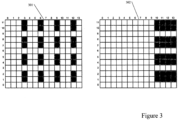
- Figure 3 illustrates a diagram of a reference signal according to certain examples.
- Figure 3 illustrates an example of a CSI reference signal pattern.
- the examples shown in Figure 3 may also be default reference signal patterns.
- Diagram 301 may be a uniform distribution 32 port CSI reference signal pattern. In other words, only 32 REs are occupied, and the spots are equally distributed. For example, the occupied REs including CSI are distributed in the third, sixth, ninth, and twelve time periods, meaning that the REs have two unoccupied time periods between each other.
- the CSI reference signal pattern only occupies the first, second, fourth, fifth, seventh, eight, tenth, and eleventh frequency REs, while the third, sixth, and ninth REs remain unoccupied.
- Diagram 302 illustrates a back loaded 32 port CSI reference signal. As can be seen in Figure 3 , all of the occupied time REs are located in the tenth, eleventh, twelve, and thirteenth time REs. The frequency REs are occupied in a similar manner to the pattern of diagram 301.
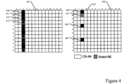
- Figure 4 illustrates a diagram of a reference signal according to certain examples.
- Figure 4 illustrates a multiplexing CSI reference signal and DMRS located within the same OFDM symbol.
- the examples shown in Figure 4 may therefore be a multifunctional reference signal pattern, in which a CSI reference signal and DMRS are multiplexed within a given resource element.
- any other type of reference signals may be multiplexed.
- no multiplexing is utilized.
- the OFDM symbol of a default reference signal pattern may include the same type of reference signal
- a multifunctional reference signal pattern may include two or more different types of reference signal patterns including same or different numerologies.
- DMRS and CSI reference signal patterns can share the same resource element.
- the DMRS and the CSI reference signal patterns can be located within the same OFDM symbol.
- diagram 401 illustrates a multi-function pattern that may be at least partially derived based on at least one default reference signal pattern.
- the multi-function reference signal pattern and the default reference signal pattern may share at least one resource element.
- the plurality of reference signal patterns may include at least one of partially overlapping or non-overlapping resource elements.
- Certain examples may use pre-configured common physical resources for downlink and/or uplink of multi-functional reference signal patterns received via RRC signaling for some or all UEs for reference signal sharing for downlink and/or uplink.
- DCI may be used by the UE and/or an uplink grant provided in a dedicated downlink control channel.
- a network entity such as a base station, may signal a UE or a group of UEs, an indication of how to construct a multi-functional reference pattern based on default reference signal patterns. The UE may use the multifunctional reference pattern to derive the locations of the REs associated with the RS pattern. The UE may then use the derived REs to perform, for example, channel estimation-based assigned RS. Additionally, the UE may utilize information relating to the structure of the RS to fine-tune the estimator parameterization of the UE, such as channel estimator parametrization.
- the multi-functional reference signal pattern in frequency and/or time can be defined per AP, per group of APs, per physical resource block (PRB), and/or per set of PRBs.
- the set of PRBs may include consecutive or non-consecutive PRBs.
- the multi-functional reference pattern may define resource elements that are allocated for UE or group of UEs for downlink reception and/or uplink transmission.
- the resource elements may either be part of the same or different reference signal pattern configured for same and/or different UEs.
- multi-functional reference signals patterns can be determined to be periodic or non-periodic in frequency. For example, every second frequency RE may be available for reception or transmission.
- resource elements may be offset. Offsetting the resource elements may include defining a resource element starting index for multi-functional reference signal patterns in a PRB. For example, by using an offset equal to two for a first AP, the RS pattern associated with the first AP may start from a third RE. In other examples, the offsetting RE may be zero or more.
- the reference signals may also include a pattern in time, where the reference signals occupy every k number of symbols in time.
- the time of the reference signal patterns may be regular or irregularity. There may also be repetition in time symbols, in which two consecutive time symbols are occupied.
- the pattern may have a symbol time offset that defines resource elements starting index for a multi-functional reference signal pattern in time.
- Figure 4 illustrates a reference signal in which a multi-functional reference signal pattern and a default reference signal pattern are included.
- Diagram 402 depicts multiplexing DMRS, zero power CSI reference signals, and data reference signals under a CSI interference measurement (CSI-IM) resource.
- CSI-IM 422, DMRS 420, and muted resource elements 421 which may be zero power CSI reference signal, may overlap.
- CSI-IM 422 may include four symbols ranging from the second and third time REs and the tenth and eleventh frequency REs. As shown in Diagram 402, however, DMRS 420 and CSI-IM 422 can overlap so that effective channel of the interference may be estimated directly inside the CSI-IM.
- Figure 5 illustrates a diagram of a reference signal according to certain examples.
- Figure 5 illustrates a setup for a multi-point transmission that may include two or more network entities.
- the pattern shown in TRP1 depicts the transmission from TRP1 of DMRS 510, 520 to a first UE.
- TRP2 illustrates transmissions from TRP2 of CSI reference signals to a second UE.
- Figure 5 illustrates default reference signal patterns, other examples may include multi-functional reference signal patterns.
- TRP2 is muting resources elements that are used for the first UE in TRP2.
- TRP2 may switch or shift the CSI reference signal pattern to another available time RE or time RE.
- the resources in the ninth time RE 540 may be shifted to the eighth time RE 530. This allows for dynamically modifying reference signal patterns that allow for multi-functioning reference signals to be transmitted and/or received.
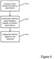
- Figure 6 illustrates a flow diagram according to certain examples.
- Figure 6 illustrates an example of a network entity, such as a base station.
- the network entity may group the resource elements into a plurality of reference signal patterns.
- the plurality of reference signal patterns may include at least one of partially overlapping or non-overlapping resource elements.
- the reference signal patterns may be included within a single OFDM symbol.
- the plurality of reference signal patterns may be constructed dynamically for a specific user or group of users.
- the resource elements may be grouped of two or more different reference signal patterns of the plurality of reference signal patterns to ensure that the resource elements do not overlap or at least partially overlap.
- the network entity constructs a reference signal including a plurality of reference signal patterns.
- the reference signal patterns may a multi-functional signal pattern for at least one of uplink or downlink.
- the network entity may coordinate the plurality of radio signal patterns between at least one of one or more cells or one or more TRPs.
- the plurality of radio signal patterns may be coordinated so as to mute at least a part of the resource elements to prevent interference of the radio signal patterns between the TRPs.
- the network entity in some examples, may also construct dynamically a selection pattern between the plurality of reference signal patterns. The UE may use such selection pattern to select an appropriate reference signal pattern.
- the reference signal is sent from the base station to the UE.
- the UE may then use the reference signal, and the plurality of radio signal patterns included therein, to determine a functionality of the user equipment based on the reference signal.
- Figure 7 illustrates a flow diagram according to certain examples.
- the user equipment may receive from a base station a reference signal comprising a plurality of reference signal patterns.
- the plurality of reference signal patterns may comprise a multi-functional signal pattern at least for one of uplink or downlink.
- the plurality of reference signal patterns may include at least one of partially overlapping or non-overlapping resource elements.
- the UE may also receive a dynamic selection pattern for the plurality of reference signal patterns, as shown in step 720.
- the plurality of reference signal patterns may be constructed dynamically for a specific user or group of users.
- the dynamic selection pattern may be used to select one of the plurality of reference signal patterns based on the dynamic selection pattern, as shown in step 730.
- the user equipment determines a functionality of the user equipment based on the reference signal.
- the functionality includes functionality at least one of downlink beam management, uplink beam management, cell specific identification acquisition, demodulation for downlink dedicated data and control, demodulation for downlink common control, uplink cell specific identification acquisition, and/or demodulation for uplink dedicated data and control.
- the handover of the user equipment may be initiated to another base station.
- the multi-functional reference signal pattern may be used to determine UE functionality without adding the separate radio signal resource.
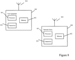
- Figure 8 illustrates a system according to certain examples. It should be understood that each signal or block in Figures 1-7 may be implemented by various means or their combinations, such as hardware, software, firmware, one or more processors and/or circuitry.
- a system may include several devices, such as, for example, network entity 820 or UE 810.
- the system may include more than one UE 810 and more than one network entity 820, although only one access node shown for the purposes of illustration.
- the network entity may be a base station, network node, an access node, a 5G NB or 5G BTS, a TRP, a server, a host, or any of the other access or network nodes discussed herein.
- Each of these devices may include at least one processor or control unit or module, respectively indicated as 811 and 821.
- At least one memory may be provided in each device, and indicated as 812 and 822, respectively.
- the memory may include computer program instructions or computer code contained therein.
- One or more transceiver 813 and 823 may be provided, and each device may also include an antenna, respectively illustrated as 814 and 824. Although only one antenna each is shown, many antennas and multiple antenna elements may be provided to each of the devices. Other configurations of these devices, for example, may be provided.
- network entity 820 and UE 810 may be additionally configured for wired communication, in addition to wireless communication, and in such a case antennas 814 and 824 may illustrate any form of communication hardware, without being limited to merely an antenna.
- Transceivers 813 and 823 may each, independently, be a transmitter, a receiver, or both a transmitter and a receiver, or a unit or device that may be configured both for transmission and reception.
- the transmitter and/or receiver (as far as radio parts are concerned) may also be implemented as a remote radio head which is not located in the device itself, but in a mast, for example.
- the operations and functionalities may be performed in different entities, such as nodes, hosts or servers, in a flexible manner. In other words, division of labor may vary case by case.
- One possible use is to make a network node deliver local content.
- One or more functionalities may also be implemented as virtual application(s) in software that can run on a server.
- a user device or user equipment 810 may be a mobile station (MS) such as a mobile phone or smart phone or multimedia device, a computer, such as a tablet, provided with wireless communication capabilities, personal data or digital assistant (PDA) provided with wireless communication capabilities, portable media player, digital camera, pocket video camera, navigation unit provided with wireless communication capabilities or any combinations thereof.
- MS mobile station
- PDA personal data or digital assistant
- portable media player digital camera
- pocket video camera navigation unit provided with wireless communication capabilities or any combinations thereof.
- the user equipment may be replaced with a machine communication device that does not require any human interaction, such as a sensor, meter, or robot.
- an apparatus such as a network entity, may include means for carrying out examples described above in relation to Figures 1-7 .
- at least one memory including computer program code can be configured to, with the at least one processor, cause the apparatus at least to perform any of the processes described herein.
- Processors 811 and 821 may be embodied by any computational or data processing device, such as a central processing unit (CPU), digital signal processor (DSP), application specific integrated circuit (ASIC), programmable logic devices (PLDs), field programmable gate arrays (FPGAs), digitally enhanced circuits, or comparable device or a combination thereof.
- the processors may be implemented as a single controller, or a plurality of controllers or processors.
- the implementation may include modules or unit of at least one chip set (for example, procedures, functions, and so on).
- Memories 8 2 and 822 may independently be any suitable storage device, such as a non-transitory computer- readable medium.
- a hard disk drive (HDD), random access memory (RAM), flash memory, or other suitable memory may be used.
- the memories may be combined on a single integrated circuit as the processor, or may be separate therefrom.
- the computer program instructions may be stored in the memory and which may be processed by the processors can be any suitable form of computer program code, for example, a compiled or interpreted computer program written in any suitable programming language.
- the memory or data storage entity is typically internal but may also be external or a combination thereof, such as in the case when additional memory capacity is obtained from a service provider.
- the memory may be fixed or removable.
- a non-transitory computer-readable medium may be encoded with computer instructions or one or more computer program (such as added or updated software routine, applet or macro) that, when executed in hardware, may perform a process such as one of the processes described herein.
- Computer programs may be coded by a programming language, which may be a high- level programming language, such as objective-C, C, C++, C#, Java, etc., or a low-level programming language, such as a machine language, or assembler. Alternatively, certain examples may be performed entirely in hardware.
- Figure 8 illustrates a system including a network entity 820 and UE 810
- certain examples may be applicable to other configurations, and configurations involving additional elements, as illustrated and discussed herein.
- multiple user equipment devices and multiple network entities may be present, or other nodes providing similar functionality, such as nodes that combine the functionality of a user equipment and a network entity, such as a relay node.
- the UE 810 may likewise be provided with a variety of configurations for communication other than communication network entity 820.
- the UE 810 may be configured for device-to-device or machine-to-machine communication.
- the above examples provide for improvements to the functioning of a network and/or to the functioning of the network entities within the network, or the user equipment communicating with the network.
- certain examples allow for different reference signals patterns with different functionalities that can be flexibly and adaptively configured for a user equipment and/or group of UEs simultaneously in uplink and/or downlink.
- multi-functional reference signal patterns transmission efficiency and radio resource utilization can be enhanced.
- overhead related to support of different radio signal pattern may be minimized, therefore removing the number of resources in the network dedicated for different radio signals.
- allowing for multiplexing of different reference signal patterns within a shared resource element may minimize or decrease process latency associated with different reference signals. Further, the above examples can also allow for the efficient leveraging of advances receivers at the user equipment.
Landscapes
- Engineering & Computer Science (AREA)
- Signal Processing (AREA)
- Computer Networks & Wireless Communication (AREA)
- Mobile Radio Communication Systems (AREA)
Claims (11)
- Procédé réalisé par une station de base, comprenant :la construction (620), au niveau de la station de base (820), d'une pluralité de motifs de signaux de référence comprenant un motif de signal de référence multifonctionnel pour au moins une parmi une liaison montante ou une liaison descendante, dans lequel le motif de signal de référence multifonctionnel comporte deux types différents ou plus de motifs de signaux de référence ayant des fonctionnalités différentes et comportant des valeurs numériques identiques ou différentes, le motif de signal de référence multifonctionnel définissant des ressources spécifiques à l'utilisateur pour un équipement utilisateur ou un groupe d'équipements utilisateurs, dans lequel les deux types différents ou plus de motifs de signaux de référence comprennent des éléments de ressource qui ne se chevauchent pas, et dans lequel les deux types différents ou plus de motifs de signaux de référence sont construits pour un utilisateur spécifique ou un groupe d'utilisateurs en utilisant une signalisation dynamique dédiée ; etl'envoi (640) d'un signal de référence de la station de base (820) à un équipement utilisateur (810) selon le motif de signal de référence multifonctionnel, pour permettre à l'équipement utilisateur de déterminer une fonctionnalité, dans lequel la fonctionnalité comprend au moins une parmi gestion de faisceau de liaison descendante, une gestion de faisceau de liaison montante, une acquisition d'identification spécifique de cellule, et/ou une acquisition d'identification spécifique de cellule de liaison montante.
- Procédé selon la revendication 1, comprenant :
le regroupement des éléments de ressources de deux motifs de signaux différents ou plus de la pluralité de motifs de signaux afin de garantir que les éléments de ressources ne se chevauchent pas ou se chevauchent au moins partiellement. - Procédé selon la revendication 1, comprenant en outre :
la construction du motif de signal de référence multifonctionnel via au moins une parmi une signalisation de contrôle de ressource radio, des informations de contrôle de liaison descendante ou un octroi de liaison montante. - Procédé selon la revendication 1, comprenant en outre :
la détermination du motif de signal de référence multifonctionnel par port d'antenne, bloc de ressources physiques, ou par un ensemble de blocs de ressources physiques. - Procédé réalisé par un équipement utilisateur, comprenant :la réception (710) d'une station de base (820), au niveau de l'équipement utilisateur (810), d'un signal de référence selon un motif de signal de référence multifonctionnel, dans lequel le motif de signal de référence multifonctionnel comprend deux types différents ou plus de motifs de signaux de référence ayant des fonctionnalités différentes, le motif de signal de référence multifonctionnel définissant des ressources spécifiques à l'utilisateur pour un équipement utilisateur ou un groupe d'équipements utilisateurs, dans lequel les deux types différents ou plus de motifs de signaux de référence comprennent des éléments de ressource qui ne se chevauchent pas, et dans lequel les deux types différents ou plus de motifs de signaux de référence sont construits pour un utilisateur spécifique ou un groupe d'utilisateurs en utilisant une signalisation dynamique dédiée ;le motif de signal de référence multifonctionnel pour au moins une parmi une liaison montante ou une liaison descendante ;la détermination (740) d'une fonctionnalité de l'équipement utilisateur (810) sur la base du signal de référence, dans lequel la fonctionnalité comprend au moins une parmi gestion de faisceau de liaison descendante, une gestion de faisceau de liaison montante, une acquisition d'identification spécifique de cellule, et/ou une acquisition d'identification spécifique de cellule de liaison montante ; etl'application de la fonctionnalité déterminée.
- Procédé selon la revendication 5, dans lequel le motif de signal de référence multifonctionnel est construit via au moins une parmi une signalisation de contrôle de ressource radio, des informations de contrôle de liaison descendante ou un octroi de liaison montante.
- Procédé selon la revendication 5, dans lequel lorsque l'équipement utilisateur est soumis à un transfert intercellulaire vers une autre station de base, le motif de signal de référence multifonctionnel est utilisé au niveau de cette autre station de base sans qu'une ressource de signal de référence distincte ne soit ajoutée au signal de référence.
- Procédé selon la revendication 5, comprenant en outre : la construction, au niveau de l'équipement utilisateur, du motif de signal de référence multifonctionnel sur la base d'un motif de signal de référence par défaut reçu, dans lequel un motif de signal de référence par défaut est un motif de signal de référence associé à un type de signal de référence.
- Appareil au niveau d'une station de base comprenant :des moyens pour construire (620), au niveau de la station de base (820), une pluralité de motifs de signaux de référence comprenant un motif de signal de référence multifonctionnel pour au moins une parmi une liaison montante ou une liaison descendante, dans lequel le motif de signal de référence multifonctionnel comporte deux types différents ou plus de motifs de signaux de référence ayant des fonctionnalités différentes et comportant des valeurs numériques identiques ou différentes, le motif de signal de référence multifonctionnel définissant des ressources spécifiques à l'utilisateur pour un équipement utilisateur ou un groupe d'équipements utilisateurs, dans lequel les deux types différents ou plus de motifs de signaux de référence comprennent des éléments de ressource qui ne se chevauchent pas, et dans lequel les deux types différents ou plus de motifs de signaux de référence sont construits pour un utilisateur spécifique ou un groupe d'utilisateurs en utilisant une signalisation dynamique dédiée ; etdes moyens pour envoyer (640) le signal de référence de la station de base (820) à un équipement utilisateur (810) selon le motif de signal de référence multifonctionnel, pour permettre à l'équipement utilisateur de déterminer une fonctionnalité, dans lequel la fonctionnalité comprend au moins une parmi gestion de faisceau de liaison descendante, une gestion de faisceau de liaison montante, une acquisition d'identification spécifique de cellule, et/ou une acquisition d'identification spécifique de cellule de liaison montante.
- Appareil au niveau d'un équipement utilisateur, comprenant :des moyens pour recevoir (710) d'une station de base (820), au niveau de l'équipement utilisateur (810), un signal de référence selon un motif de signal de référence multifonctionnel, dans lequel le motif de signal de référence multifonctionnel comprend deux types différents ou plus de motifs de signaux de référence ayant des fonctionnalités différentes comprenant des valeurs numériques identiques ou différentes, le motif de signal de référence multifonctionnel pour au moins une parmi une liaison montante ou une liaison descendante, le motif de signal de référence multifonctionnel définissant des ressources spécifiques à l'utilisateur pour un équipement utilisateur ou un groupe d'équipements utilisateurs, dans lequel les deux types différents ou plus de motifs de signaux comprennent des éléments de ressource qui ne se chevauchent pas, et dans lequel les deux types différents ou plus de motifs de signaux de référence sont construits pour un utilisateur spécifique ou un groupe d'utilisateurs en utilisant une signalisation dynamique dédiée ;des moyens pour déterminer (740) une fonctionnalité de l'équipement utilisateur (810) sur la base du signal de référence, dans lequel la fonctionnalité comprend au moins une parmi gestion de faisceau de liaison descendante, une gestion de faisceau de liaison montante, une acquisition d'identification spécifique de cellule, et/ou une acquisition d'identification spécifique de cellule de liaison montante ; etdes moyens pour appliquer la fonctionnalité déterminée.
- Produit de programme informatique comprenant des instructions qui, lorsque le programme est exécuté par un ordinateur, amènent l'ordinateur à mettre en œuvre le processus selon l'une des revendications 1 à 8.
Priority Applications (1)
| Application Number | Priority Date | Filing Date | Title |
|---|---|---|---|
| EP24223028.2A EP4510517A3 (fr) | 2017-01-05 | 2017-01-05 | Motifs de signal de référence |
Applications Claiming Priority (1)
| Application Number | Priority Date | Filing Date | Title |
|---|---|---|---|
| PCT/EP2017/000010 WO2018127265A1 (fr) | 2017-01-05 | 2017-01-05 | Motifs de signal de référence |
Related Child Applications (2)
| Application Number | Title | Priority Date | Filing Date |
|---|---|---|---|
| EP24223028.2A Division-Into EP4510517A3 (fr) | 2017-01-05 | 2017-01-05 | Motifs de signal de référence |
| EP24223028.2A Division EP4510517A3 (fr) | 2017-01-05 | 2017-01-05 | Motifs de signal de référence |
Publications (2)
| Publication Number | Publication Date |
|---|---|
| EP3566362A1 EP3566362A1 (fr) | 2019-11-13 |
| EP3566362B1 true EP3566362B1 (fr) | 2025-01-29 |
Family
ID=57777623
Family Applications (2)
| Application Number | Title | Priority Date | Filing Date |
|---|---|---|---|
| EP17700189.8A Active EP3566362B1 (fr) | 2017-01-05 | 2017-01-05 | Motifs de signal de référence |
| EP24223028.2A Pending EP4510517A3 (fr) | 2017-01-05 | 2017-01-05 | Motifs de signal de référence |
Family Applications After (1)
| Application Number | Title | Priority Date | Filing Date |
|---|---|---|---|
| EP24223028.2A Pending EP4510517A3 (fr) | 2017-01-05 | 2017-01-05 | Motifs de signal de référence |
Country Status (3)
| Country | Link |
|---|---|
| US (1) | US11184127B2 (fr) |
| EP (2) | EP3566362B1 (fr) |
| WO (1) | WO2018127265A1 (fr) |
Families Citing this family (2)
| Publication number | Priority date | Publication date | Assignee | Title |
|---|---|---|---|---|
| US11277245B2 (en) * | 2017-08-10 | 2022-03-15 | Sony Corporation | Telecommunications apparatus and methods |
| JP7424485B2 (ja) * | 2020-06-15 | 2024-01-30 | 日本電信電話株式会社 | 無線通信システム、無線通信システムの制御方法、無線通信システムの制御装置、及び無線通信システム制御プログラム |
Family Cites Families (6)
| Publication number | Priority date | Publication date | Assignee | Title |
|---|---|---|---|---|
| US9136997B2 (en) * | 2010-05-04 | 2015-09-15 | Qualcomm Incorporated | Methods and apparatuses for using channel state information reference signals |
| US9332479B2 (en) * | 2012-01-04 | 2016-05-03 | Ofinno Technologies, Llc | Network site for wireless communications |
| US8964705B2 (en) * | 2013-02-14 | 2015-02-24 | Blackberry Limited | For small cell demodulation reference signal and initial synchronization |
| JP6282727B2 (ja) * | 2013-05-08 | 2018-02-21 | ゼットティーイー ウィストロン テレコム エービー | HetNet配置における座標インディケータの使用 |
| EP2874454A1 (fr) | 2013-11-15 | 2015-05-20 | Fujitsu Limited | Signaux de référence dans une communication sans fil |
| JP6987788B2 (ja) * | 2016-05-13 | 2022-01-05 | テレフオンアクチーボラゲット エルエム エリクソン(パブル) | 低減密度csi−rsのための機構 |
-
2017
- 2017-01-05 EP EP17700189.8A patent/EP3566362B1/fr active Active
- 2017-01-05 EP EP24223028.2A patent/EP4510517A3/fr active Pending
- 2017-01-05 US US16/475,453 patent/US11184127B2/en active Active
- 2017-01-05 WO PCT/EP2017/000010 patent/WO2018127265A1/fr not_active Ceased
Also Published As
| Publication number | Publication date |
|---|---|
| US11184127B2 (en) | 2021-11-23 |
| EP4510517A3 (fr) | 2025-02-26 |
| EP3566362A1 (fr) | 2019-11-13 |
| US20200028644A1 (en) | 2020-01-23 |
| WO2018127265A1 (fr) | 2018-07-12 |
| EP4510517A2 (fr) | 2025-02-19 |
Similar Documents
| Publication | Publication Date | Title |
|---|---|---|
| JP7321707B2 (ja) | 方法、システムおよび装置 | |
| KR102481397B1 (ko) | 다중 입력 다중 출력 무선 시스템을 위한 사운딩 기준 신호 전력 제어 | |
| US10743195B2 (en) | Communication method and apparatus | |
| CN115956353B (zh) | 全双工定时提前增强 | |
| JP6913171B2 (ja) | ハンドオーバのためのビームを選択する方法、コンピュータプログラム、及び装置 | |
| EP3520228B1 (fr) | Signal de référence avec apprentissage de formation de faisceau et estimation de canal | |
| CN111901020A (zh) | 一种功率控制参数确定方法、设备和存储介质 | |
| CN110972251A (zh) | 信号传输方法、相关设备及系统 | |
| EP3456017B1 (fr) | Hypothèses de colocalisation d'antennes et de récepteurs | |
| CN110351058B (zh) | 一种信号传输方法及通信设备 | |
| WO2011160670A1 (fr) | Transmission de signaux de référence | |
| WO2012102483A1 (fr) | Procédé de retour d'informations d'état de canal et appareil dans un système multinodal | |
| EP3566362B1 (fr) | Motifs de signal de référence | |
| CN115334601B (zh) | 一种小区间测量上报方法、设备、装置及存储介质 | |
| WO2022236657A1 (fr) | Procédé et appareil pour déterminer une position de période de garde pour une commutation d'antenne srs | |
| HK40124730A (en) | Reference signal patterns | |
| JP2021083108A (ja) | 方法、システムおよび装置 | |
| CN120090674A (zh) | 用于增强测量和报告的方法 | |
| WO2024191331A1 (fr) | Adaptation de débit statique et dynamique d'équipement utilisateur de nouvelle radio | |
| WO2025113937A1 (fr) | Procédé pour mesures et rapports améliorés |
Legal Events
| Date | Code | Title | Description |
|---|---|---|---|
| STAA | Information on the status of an ep patent application or granted ep patent |
Free format text: STATUS: UNKNOWN |
|
| STAA | Information on the status of an ep patent application or granted ep patent |
Free format text: STATUS: THE INTERNATIONAL PUBLICATION HAS BEEN MADE |
|
| PUAI | Public reference made under article 153(3) epc to a published international application that has entered the european phase |
Free format text: ORIGINAL CODE: 0009012 |
|
| STAA | Information on the status of an ep patent application or granted ep patent |
Free format text: STATUS: REQUEST FOR EXAMINATION WAS MADE |
|
| 17P | Request for examination filed |
Effective date: 20190805 |
|
| AK | Designated contracting states |
Kind code of ref document: A1 Designated state(s): AL AT BE BG CH CY CZ DE DK EE ES FI FR GB GR HR HU IE IS IT LI LT LU LV MC MK MT NL NO PL PT RO RS SE SI SK SM TR |
|
| AX | Request for extension of the european patent |
Extension state: BA ME |
|
| DAV | Request for validation of the european patent (deleted) | ||
| DAX | Request for extension of the european patent (deleted) | ||
| STAA | Information on the status of an ep patent application or granted ep patent |
Free format text: STATUS: EXAMINATION IS IN PROGRESS |
|
| 17Q | First examination report despatched |
Effective date: 20201021 |
|
| GRAP | Despatch of communication of intention to grant a patent |
Free format text: ORIGINAL CODE: EPIDOSNIGR1 |
|
| STAA | Information on the status of an ep patent application or granted ep patent |
Free format text: STATUS: GRANT OF PATENT IS INTENDED |
|
| RIC1 | Information provided on ipc code assigned before grant |
Ipc: H04L 5/14 20060101ALN20241009BHEP Ipc: H04B 7/06 20060101ALN20241009BHEP Ipc: H04L 27/26 20060101ALI20241009BHEP Ipc: H04B 7/08 20060101ALI20241009BHEP Ipc: H04L 5/00 20060101AFI20241009BHEP |
|
| INTG | Intention to grant announced |
Effective date: 20241018 |
|
| GRAS | Grant fee paid |
Free format text: ORIGINAL CODE: EPIDOSNIGR3 |
|
| GRAA | (expected) grant |
Free format text: ORIGINAL CODE: 0009210 |
|
| STAA | Information on the status of an ep patent application or granted ep patent |
Free format text: STATUS: THE PATENT HAS BEEN GRANTED |
|
| AK | Designated contracting states |
Kind code of ref document: B1 Designated state(s): AL AT BE BG CH CY CZ DE DK EE ES FI FR GB GR HR HU IE IS IT LI LT LU LV MC MK MT NL NO PL PT RO RS SE SI SK SM TR |
|
| REG | Reference to a national code |
Ref country code: GB Ref legal event code: FG4D |
|
| REG | Reference to a national code |
Ref country code: CH Ref legal event code: EP |
|
| REG | Reference to a national code |
Ref country code: DE Ref legal event code: R096 Ref document number: 602017087532 Country of ref document: DE |
|
| REG | Reference to a national code |
Ref country code: IE Ref legal event code: FG4D |
|
| REG | Reference to a national code |
Ref country code: NL Ref legal event code: MP Effective date: 20250129 |
|
| PG25 | Lapsed in a contracting state [announced via postgrant information from national office to epo] |
Ref country code: NL Free format text: LAPSE BECAUSE OF FAILURE TO SUBMIT A TRANSLATION OF THE DESCRIPTION OR TO PAY THE FEE WITHIN THE PRESCRIBED TIME-LIMIT Effective date: 20250129 |
|
| PG25 | Lapsed in a contracting state [announced via postgrant information from national office to epo] |
Ref country code: RS Free format text: LAPSE BECAUSE OF FAILURE TO SUBMIT A TRANSLATION OF THE DESCRIPTION OR TO PAY THE FEE WITHIN THE PRESCRIBED TIME-LIMIT Effective date: 20250429 |
|
| PG25 | Lapsed in a contracting state [announced via postgrant information from national office to epo] |
Ref country code: FI Free format text: LAPSE BECAUSE OF FAILURE TO SUBMIT A TRANSLATION OF THE DESCRIPTION OR TO PAY THE FEE WITHIN THE PRESCRIBED TIME-LIMIT Effective date: 20250129 |
|
| PG25 | Lapsed in a contracting state [announced via postgrant information from national office to epo] |
Ref country code: PL Free format text: LAPSE BECAUSE OF FAILURE TO SUBMIT A TRANSLATION OF THE DESCRIPTION OR TO PAY THE FEE WITHIN THE PRESCRIBED TIME-LIMIT Effective date: 20250129 |
|
| PG25 | Lapsed in a contracting state [announced via postgrant information from national office to epo] |
Ref country code: ES Free format text: LAPSE BECAUSE OF FAILURE TO SUBMIT A TRANSLATION OF THE DESCRIPTION OR TO PAY THE FEE WITHIN THE PRESCRIBED TIME-LIMIT Effective date: 20250129 |
|
| REG | Reference to a national code |
Ref country code: LT Ref legal event code: MG9D |
|
| PG25 | Lapsed in a contracting state [announced via postgrant information from national office to epo] |
Ref country code: IS Free format text: LAPSE BECAUSE OF FAILURE TO SUBMIT A TRANSLATION OF THE DESCRIPTION OR TO PAY THE FEE WITHIN THE PRESCRIBED TIME-LIMIT Effective date: 20250529 Ref country code: NO Free format text: LAPSE BECAUSE OF FAILURE TO SUBMIT A TRANSLATION OF THE DESCRIPTION OR TO PAY THE FEE WITHIN THE PRESCRIBED TIME-LIMIT Effective date: 20250429 |
|
| REG | Reference to a national code |
Ref country code: AT Ref legal event code: MK05 Ref document number: 1764514 Country of ref document: AT Kind code of ref document: T Effective date: 20250129 |
|
| PG25 | Lapsed in a contracting state [announced via postgrant information from national office to epo] |
Ref country code: HR Free format text: LAPSE BECAUSE OF FAILURE TO SUBMIT A TRANSLATION OF THE DESCRIPTION OR TO PAY THE FEE WITHIN THE PRESCRIBED TIME-LIMIT Effective date: 20250129 |
|
| PG25 | Lapsed in a contracting state [announced via postgrant information from national office to epo] |
Ref country code: LV Free format text: LAPSE BECAUSE OF FAILURE TO SUBMIT A TRANSLATION OF THE DESCRIPTION OR TO PAY THE FEE WITHIN THE PRESCRIBED TIME-LIMIT Effective date: 20250129 Ref country code: PT Free format text: LAPSE BECAUSE OF FAILURE TO SUBMIT A TRANSLATION OF THE DESCRIPTION OR TO PAY THE FEE WITHIN THE PRESCRIBED TIME-LIMIT Effective date: 20250529 |
|
| PG25 | Lapsed in a contracting state [announced via postgrant information from national office to epo] |
Ref country code: GR Free format text: LAPSE BECAUSE OF FAILURE TO SUBMIT A TRANSLATION OF THE DESCRIPTION OR TO PAY THE FEE WITHIN THE PRESCRIBED TIME-LIMIT Effective date: 20250430 Ref country code: BG Free format text: LAPSE BECAUSE OF FAILURE TO SUBMIT A TRANSLATION OF THE DESCRIPTION OR TO PAY THE FEE WITHIN THE PRESCRIBED TIME-LIMIT Effective date: 20250129 |
|
| PG25 | Lapsed in a contracting state [announced via postgrant information from national office to epo] |
Ref country code: AT Free format text: LAPSE BECAUSE OF FAILURE TO SUBMIT A TRANSLATION OF THE DESCRIPTION OR TO PAY THE FEE WITHIN THE PRESCRIBED TIME-LIMIT Effective date: 20250129 |
|
| PG25 | Lapsed in a contracting state [announced via postgrant information from national office to epo] |
Ref country code: SE Free format text: LAPSE BECAUSE OF FAILURE TO SUBMIT A TRANSLATION OF THE DESCRIPTION OR TO PAY THE FEE WITHIN THE PRESCRIBED TIME-LIMIT Effective date: 20250129 |
|
| PG25 | Lapsed in a contracting state [announced via postgrant information from national office to epo] |
Ref country code: SM Free format text: LAPSE BECAUSE OF FAILURE TO SUBMIT A TRANSLATION OF THE DESCRIPTION OR TO PAY THE FEE WITHIN THE PRESCRIBED TIME-LIMIT Effective date: 20250129 |
|
| PG25 | Lapsed in a contracting state [announced via postgrant information from national office to epo] |
Ref country code: DK Free format text: LAPSE BECAUSE OF FAILURE TO SUBMIT A TRANSLATION OF THE DESCRIPTION OR TO PAY THE FEE WITHIN THE PRESCRIBED TIME-LIMIT Effective date: 20250129 |
|
| PG25 | Lapsed in a contracting state [announced via postgrant information from national office to epo] |
Ref country code: IT Free format text: LAPSE BECAUSE OF FAILURE TO SUBMIT A TRANSLATION OF THE DESCRIPTION OR TO PAY THE FEE WITHIN THE PRESCRIBED TIME-LIMIT Effective date: 20250129 |
|
| PG25 | Lapsed in a contracting state [announced via postgrant information from national office to epo] |
Ref country code: EE Free format text: LAPSE BECAUSE OF FAILURE TO SUBMIT A TRANSLATION OF THE DESCRIPTION OR TO PAY THE FEE WITHIN THE PRESCRIBED TIME-LIMIT Effective date: 20250129 Ref country code: CZ Free format text: LAPSE BECAUSE OF FAILURE TO SUBMIT A TRANSLATION OF THE DESCRIPTION OR TO PAY THE FEE WITHIN THE PRESCRIBED TIME-LIMIT Effective date: 20250129 |
|
| PG25 | Lapsed in a contracting state [announced via postgrant information from national office to epo] |
Ref country code: RO Free format text: LAPSE BECAUSE OF FAILURE TO SUBMIT A TRANSLATION OF THE DESCRIPTION OR TO PAY THE FEE WITHIN THE PRESCRIBED TIME-LIMIT Effective date: 20250129 |
|
| PG25 | Lapsed in a contracting state [announced via postgrant information from national office to epo] |
Ref country code: SK Free format text: LAPSE BECAUSE OF FAILURE TO SUBMIT A TRANSLATION OF THE DESCRIPTION OR TO PAY THE FEE WITHIN THE PRESCRIBED TIME-LIMIT Effective date: 20250129 |
|
| REG | Reference to a national code |
Ref country code: DE Ref legal event code: R097 Ref document number: 602017087532 Country of ref document: DE |
|
| PLBE | No opposition filed within time limit |
Free format text: ORIGINAL CODE: 0009261 |
|
| STAA | Information on the status of an ep patent application or granted ep patent |
Free format text: STATUS: NO OPPOSITION FILED WITHIN TIME LIMIT |
|
| 26N | No opposition filed |
Effective date: 20251030 |
|
| PGFP | Annual fee paid to national office [announced via postgrant information from national office to epo] |
Ref country code: GB Payment date: 20251204 Year of fee payment: 10 |
|
| PGFP | Annual fee paid to national office [announced via postgrant information from national office to epo] |
Ref country code: FR Payment date: 20251208 Year of fee payment: 10 |
|
| PGFP | Annual fee paid to national office [announced via postgrant information from national office to epo] |
Ref country code: DE Payment date: 20251203 Year of fee payment: 10 |