EP3566543B1 - Blanking einer uplink-übertragung - Google Patents
Blanking einer uplink-übertragung Download PDFInfo
- Publication number
- EP3566543B1 EP3566543B1 EP17889970.4A EP17889970A EP3566543B1 EP 3566543 B1 EP3566543 B1 EP 3566543B1 EP 17889970 A EP17889970 A EP 17889970A EP 3566543 B1 EP3566543 B1 EP 3566543B1
- Authority
- EP
- European Patent Office
- Prior art keywords
- uplink transmission
- signal
- symbols
- blanked
- remote unit
- Prior art date
- Legal status (The legal status is an assumption and is not a legal conclusion. Google has not performed a legal analysis and makes no representation as to the accuracy of the status listed.)
- Active
Links
Images


Classifications
-
- H—ELECTRICITY
- H04—ELECTRIC COMMUNICATION TECHNIQUE
- H04L—TRANSMISSION OF DIGITAL INFORMATION, e.g. TELEGRAPHIC COMMUNICATION
- H04L5/00—Arrangements affording multiple use of the transmission path
- H04L5/0091—Signalling for the administration of the divided path, e.g. signalling of configuration information
- H04L5/0094—Indication of how sub-channels of the path are allocated
-
- H—ELECTRICITY
- H04—ELECTRIC COMMUNICATION TECHNIQUE
- H04W—WIRELESS COMMUNICATION NETWORKS
- H04W72/00—Local resource management
- H04W72/20—Control channels or signalling for resource management
- H04W72/23—Control channels or signalling for resource management in the downlink direction of a wireless link, i.e. towards a terminal
-
- H—ELECTRICITY
- H04—ELECTRIC COMMUNICATION TECHNIQUE
- H04W—WIRELESS COMMUNICATION NETWORKS
- H04W72/00—Local resource management
- H04W72/50—Allocation or scheduling criteria for wireless resources
- H04W72/535—Allocation or scheduling criteria for wireless resources based on resource usage policies
-
- H—ELECTRICITY
- H04—ELECTRIC COMMUNICATION TECHNIQUE
- H04W—WIRELESS COMMUNICATION NETWORKS
- H04W72/00—Local resource management
- H04W72/50—Allocation or scheduling criteria for wireless resources
- H04W72/56—Allocation or scheduling criteria for wireless resources based on priority criteria
-
- H—ELECTRICITY
- H04—ELECTRIC COMMUNICATION TECHNIQUE
- H04W—WIRELESS COMMUNICATION NETWORKS
- H04W88/00—Devices specially adapted for wireless communication networks, e.g. terminals, base stations or access point devices
-
- H—ELECTRICITY
- H04—ELECTRIC COMMUNICATION TECHNIQUE
- H04L—TRANSMISSION OF DIGITAL INFORMATION, e.g. TELEGRAPHIC COMMUNICATION
- H04L5/00—Arrangements affording multiple use of the transmission path
- H04L5/003—Arrangements for allocating sub-channels of the transmission path
-
- H—ELECTRICITY
- H04—ELECTRIC COMMUNICATION TECHNIQUE
- H04W—WIRELESS COMMUNICATION NETWORKS
- H04W72/00—Local resource management
- H04W72/12—Wireless traffic scheduling
- H04W72/1263—Mapping of traffic onto schedule, e.g. scheduled allocation or multiplexing of flows
- H04W72/1268—Mapping of traffic onto schedule, e.g. scheduled allocation or multiplexing of flows of uplink data flows
Definitions
- the subject matter disclosed herein relates generally to wireless communications and more particularly relates to uplink transmission blanking.
- TDM Transmission Time Interval
- TX Transmit
- UCI Uplink Control Information
- UE User Entity/Equipment
- UL Uplink
- UMTS Universal Mobile Telecommunications System
- UpPTS Uplink Pilot Time Slot
- URLLC Ultra-reliability and Low-latency Communications
- WiMAX Worldwide Interoperability for Microwave Access
- HARQ-ACK may represent collectively the Positive Acknowledge (“ACK”) and the Negative Acknowledge (“NAK”). ACK means that a TB is correctly received while NAK means a TB is erroneously received.
- URLLC may have a data payload that is small.
- URLLC may have a periodically occurring packet arrival rate and a packet size may be 32 bytes, 50 bytes, 200 bytes, and so forth.
- the one-way user plane latency may be 0.5 ms for UL, and 0.5 ms for DL.
- URLLC reliability may be evaluated by a success probability of transmitting X bytes within 1 ms. This may be the time it takes to deliver a small data packet from the radio protocol layer 2/3 service data unit ("SDU") ingress point to the radio protocol layer 2/3 SDU egress point of the radio interface, at a certain channel quality (e.g., coverage-edge).
- the target for reliability may be 1-10 -5 within 1ms.
- a general URLLC reliability requirement for one transmission of a packet may be 1-10 -5 for X bytes (e.g., 20 bytes) with a user plane latency of 1ms.
- R1-1612097 is a 3GPP discussion document titled "on data transmission to support multiplexing of eMBB and URLLC" submitted by Lenovo to the RAN WG1 meeting #87 in Reno, USA on 14th November 2016 , and describes the multiplexing of eMBB and URLLC in different scenarios.
- R1-1612582 is a 3GPP discussion paper titled "Uplink URLLC and eMBB multiplexing options" submitted by Intel Corporation to the RAN WG1 meeting #87 in Reno, USA on 14th November 2016 , and describes different options for UL URLLC and eMBB multiplexing and implications on physical layer design.
- R1-1611849 is a 3GPP discussion paper titled "On multiplexing between eMBB and URLLC" submitted by LG Electronics to the RAN WG1 meeting #87 in Reno, USA on 14th November 2016 , and describes multiplexing of eMBB and URLLC and the evaluation results on URLLC impact on eMBB data transmission.
- R1-1610082 is a 3GPP discussion paper titled "Multiplexing mechanism for eMBB and URLLC" submitted by NTT DOCOMO to the RAN WG1 meeting #86 in Lisbon, Portugal on 10th October 2016 , and describes a multiplexing mechanism for eMBB and URLLC including aspects related to uplink scheduling.
- R1-167391 is a 3GPP discussion document titled "On co-existence of eMBB and URLLC" submitted by NTT DOCOMO, Inc. to the RAN WG1 meeting #86 in Gotheberg, Swedne on 22nd August 2016 , and describes a single numerology and mixed numerology by LTE transparent manner for initial phase of URLLC support.
- R1-162131 is a 3GPP discussion document titled "Discussion on CCA gap and symbol position for PUSCH and SRS for eLAA" submitted by Huawei and HISilicon at the TSG RAN WG1 meeting #84bis in Busan, Korea, on 11th April 2016 , and describes UCI transmission for eLAA including blanking either the starting symbols or the end symbols in a subframe.
- US 2016/0014753 A1 describes time domain multiplexing uplink transmission on multiple serving cells for a mobile station with a single transmitter.
- US 2016/0227557 A1 describes a method for providing a transmission skipping policy to improve performance in a multi-subscriber identity module (SIM) wireless communication device.
- SIM subscriber identity module
- Claim 1 defines an apparatus
- claim 7 defines a method in a remote unit
- claim 10 defines an apparatus
- claim 11 defines a method on a base unit.
- the apparatus includes a receiver that: receives a first signal from a base unit, wherein the first signal is used for indicating scheduling information for a first uplink transmission; and receives a third signal from the base unit.
- the third signal is used for determining a first one or more symbols of the first uplink transmission to be blanked.
- the apparatus also includes a processor that determines the first one or more symbols of the first uplink transmission to be blanked based on the third signal.
- the apparatus includes a transmitter that transmits the first uplink transmission to the base unit with the first one or more symbols blanked.
- the third signal indicates the first one or more symbols of the first uplink transmission to be blanked. In a further embodiment, the third signal indicates a number of symbols to be blanked at a beginning of the first uplink transmission. In certain embodiments, the third signal is included in the first signal. In some embodiments, the third signal is used to indicate a transmission resource for a second uplink transmission.
- the first one or more symbols of the first uplink transmission are blanked in response to the first uplink transmission immediately following the transmission resource for the second uplink transmission.
- a priority of the first uplink transmission is lower than a priority of the second uplink transmission.
- the processor determines the first one or more symbols of the first uplink transmission to be blanked based on cell coverage, subcarrier spacing, timing offset between the first uplink transmission and the second uplink transmission, or some combination thereof.
- the first one or more symbols of the first uplink transmission are blanked by puncturing.
- the first one or more symbols of the first uplink transmission are blanked by rate matching.
- a method for uplink transmission blanking includes receiving a first signal from a base unit.
- the first signal is used for indicating scheduling information for a first uplink transmission.
- the method also includes receiving a third signal from the base unit.
- the third signal is used for determining a first one or more symbols of the first uplink transmission to be blanked.
- the method includes determining the first one or more symbols of the first uplink transmission to be blanked based on the third signal.
- the method also includes transmitting the first uplink transmission to the base unit with the first one or more symbols blanked.
- an apparatus in one embodiment, includes a transmitter that: transmits a first signal to a first remote unit, wherein the first signal is used to indicate scheduling information for the first remote unit for a first uplink transmission; transmits a second signal to a second remote unit, wherein the second signal is used to indicate a transmission resource for the second remote unit for a second uplink transmission; and transmits a third signal to the first remote unit, wherein the third signal is used for the first remote unit to determine the first one or more symbols of the first uplink transmission to be blanked.
- the apparatus also includes a processor that determines the first one or more symbols of the first uplink transmission to be blanked.
- the apparatus includes a receiver that receives the first uplink transmission from the first remote unit with the first one or more symbols blanked.
- the third signal indicates the first one or more symbols of the first uplink transmission to be blanked. In a further embodiment, the third signal indicates a number of symbols to be blanked at a beginning of the first uplink transmission. In certain embodiments, the third signal is included in the first signal. In some embodiments, the processor determines the first one or more symbols of the first uplink transmission to be blanked based on cell coverage, subcarrier spacing, timing offset between the first uplink transmission and the second uplink transmission, or some combination thereof.
- the third signal is the same as the second signal.
- the first one or more symbols of the first uplink transmission are blanked in response to the first uplink transmission immediately following the second uplink transmission.
- a priority of the first uplink transmission is lower than a priority of the second uplink transmission.
- the first one or more symbols of the first uplink transmission are blanked by puncturing.
- the first one or more symbols of the first uplink transmission are blanked by rate matching.
- a method for uplink transmission blanking includes transmitting a first signal to a first remote unit, wherein the first signal is used to indicate scheduling information for the first remote unit for a first uplink transmission.
- the method includes transmitting a second signal to a second remote unit, wherein the second signal is used to indicate a transmission resource for the second remote unit for a second uplink transmission.
- the method also includes transmitting a third signal to the first remote unit, wherein the third signal is used for the first remote unit to determine the first one or more symbols of the first uplink transmission to be blanked.
- the method includes determining the first one or more symbols of the first uplink transmission to be blanked.
- the method includes receiving the first uplink transmission from the first remote unit with the first one or more symbols blanked.
- embodiments may be embodied as a system, apparatus, method, or program product. Accordingly, embodiments may take the form of an entirely hardware embodiment, an entirely software embodiment (including firmware, resident software, micro-code, etc.) or an embodiment combining software and hardware aspects that may all generally be referred to herein as a "circuit," "module” or “system.” Furthermore, embodiments may take the form of a program product embodied in one or more computer readable storage devices storing machine readable code, computer readable code, and/or program code, referred hereafter as code. The storage devices may be tangible, non-transitory, and/or non-transmission. The storage devices may not embody signals. In a certain embodiment, the storage devices only employ signals for accessing code.
- modules may be implemented as a hardware circuit comprising custom very-large-scale integration ("VLSI") circuits or gate arrays, off-the-shelf semiconductors such as logic chips, transistors, or other discrete components.
- VLSI very-large-scale integration
- a module may also be implemented in programmable hardware devices such as field programmable gate arrays, programmable array logic, programmable logic devices or the like.
- Modules may also be implemented in code and/or software for execution by various types of processors.
- An identified module of code may, for instance, include one or more physical or logical blocks of executable code which may, for instance, be organized as an object, procedure, or function. Nevertheless, the executables of an identified module need not be physically located together, but may include disparate instructions stored in different locations which, when joined logically together, include the module and achieve the stated purpose for the module.
- a module of code may be a single instruction, or many instructions, and may even be distributed over several different code segments, among different programs, and across several memory devices.
- operational data may be identified and illustrated herein within modules, and may be embodied in any suitable form and organized within any suitable type of data structure. The operational data may be collected as a single data set, or may be distributed over different locations including over different computer readable storage devices.
- the software portions are stored on one or more computer readable storage devices.
- the computer readable medium may be a computer readable storage medium.
- the computer readable storage medium may be a storage device storing the code.
- the storage device may be, for example, but not limited to, an electronic, magnetic, optical, electromagnetic, infrared, holographic, micromechanical, or semiconductor system, apparatus, or device, or any suitable combination of the foregoing.
- a storage device More specific examples (a non-exhaustive list) of the storage device would include the following: an electrical connection having one or more wires, a portable computer diskette, a hard disk, a random access memory (“RAM”), a read-only memory (“ROM”), an erasable programmable read-only memory (“EPROM” or Flash memory), a portable compact disc read-only memory (“CD-ROM”), an optical storage device, a magnetic storage device, or any suitable combination of the foregoing.
- a computer readable storage medium may be any tangible medium that can contain, or store a program for use by or in connection with an instruction execution system, apparatus, or device.
- Code for carrying out operations for embodiments may be any number of lines and may be written in any combination of one or more programming languages including an object oriented programming language such as Python, Ruby, Java, Smalltalk, C++, or the like, and conventional procedural programming languages, such as the "C" programming language, or the like, and/or machine languages such as assembly languages.
- the code may execute entirely on the user's computer, partly on the user's computer, as a stand-alone software package, partly on the user's computer and partly on a remote computer or entirely on the remote computer or server.
- the remote computer may be connected to the user's computer through any type of network, including a local area network (“LAN”) or a wide area network (“WAN”), or the connection may be made to an external computer (for example, through the Internet using an Internet Service Provider).
- LAN local area network
- WAN wide area network
- Internet Service Provider an Internet Service Provider
- the code may also be stored in a storage device that can direct a computer, other programmable data processing apparatus, or other devices to function in a particular manner, such that the instructions stored in the storage device produce an article of manufacture including instructions which implement the function/act specified in the schematic flowchart diagrams and/or schematic block diagrams block or blocks.
- the code may also be loaded onto a computer, other programmable data processing apparatus, or other devices to cause a series of operational steps to be performed on the computer, other programmable apparatus or other devices to produce a computer implemented process such that the code which execute on the computer or other programmable apparatus provide processes for implementing the functions/acts specified in the flowchart and/or block diagram block or blocks.
- each block in the schematic flowchart diagrams and/or schematic block diagrams may represent a module, segment, or portion of code, which includes one or more executable instructions of the code for implementing the specified logical function(s).
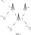
- Figure 1 depicts an embodiment of a wireless communication system 100 for uplink transmission blanking.
- the wireless communication system 100 includes remote units 102 and base units 104. Even though a specific number of remote units 102 and base units 104 are depicted in Figure 1 , one of skill in the art will recognize that any number of remote units 102 and base units 104 may be included in the wireless communication system 100.
- the remote units 102 may include computing devices, such as desktop computers, laptop computers, personal digital assistants ("PDAs"), tablet computers, smart phones, smart televisions (e.g., televisions connected to the Internet), set-top boxes, game consoles, security systems (including security cameras), vehicle on-board computers, network devices (e.g., routers, switches, modems), or the like.
- the remote units 102 include wearable devices, such as smart watches, fitness bands, optical head-mounted displays, or the like.
- the remote units 102 may be referred to as subscriber units, mobiles, mobile stations, users, terminals, mobile terminals, fixed terminals, subscriber stations, UE, user terminals, a device, or by other terminology used in the art.
- the remote units 102 may communicate directly with one or more of the base units 104 via UL communication signals.
- the base units 104 may be distributed over a geographic region.
- a base unit 104 may also be referred to as an access point, an access terminal, a base, a base station, a Node-B, an eNB, a gNB, a Home Node-B, a relay node, a device, or by any other terminology used in the art.
- the base units 104 are generally part of a radio access network that includes one or more controllers communicably coupled to one or more corresponding base units 104.
- the radio access network is generally communicably coupled to one or more core networks, which may be coupled to other networks, like the Internet and public switched telephone networks, among other networks. These and other elements of radio access and core networks are not illustrated but are well known generally by those having ordinary skill in the art.
- the wireless communication system 100 is compliant with the LTE of the 3GPP protocol, wherein the base unit 104 transmits using an OFDM modulation scheme on the DL and the remote units 102 transmit on the UL using a SC-FDMA scheme or an OFDM scheme. More generally, however, the wireless communication system 100 may implement some other open or proprietary communication protocol, for example, WiMAX, among other protocols. The present disclosure is not intended to be limited to the implementation of any particular wireless communication system architecture or protocol.
- the base units 104 may serve a number of remote units 102 within a serving area, for example, a cell or a cell sector via a wireless communication link.
- the base units 104 transmit DL communication signals to serve the remote units 102 in the time, frequency, and/or spatial domain.
- a base unit 104 may transmit a first signal to a first remote unit 102.
- the first signal may be used to indicate scheduling information for the first remote unit 102 for a first uplink transmission.
- the base unit 104 may transmit a second signal to a second remote unit 102.
- the second signal may be used to indicate a transmission resource for the second remote unit 102 for a second uplink transmission.
- the base unit 104 may transmit a third signal to the first remote unit 102. In such embodiments, the third signal may be used for the first remote unit 102 to determine the first one or more symbols of the first uplink transmission to be blanked.
- the base unit 104 may determine the first one or more symbols of the first uplink transmission to be blanked. In one embodiment, the base unit 104 may receive the first uplink transmission from the first remote unit 102 with the first one or more symbols blanked. Accordingly, a base unit 104 may be used to receive uplink transmission blanking.
- a remote unit 102 may receive a first signal from a base unit 104.
- the first signal may be used for indicating scheduling information for a first uplink transmission.
- the remote unit 102 may receive a third signal from the base unit 104.
- the third signal may be used for determining a first one or more symbols of the first uplink transmission to be blanked.
- the remote unit 102 may determine the first one or more symbols of the first uplink transmission to be blanked based on the third signal.
- the remote unit 102 may transmit the first uplink transmission to the base unit 104 with the first one or more symbols blanked. Accordingly, a remote unit 102 may be used for uplink transmission blanking.
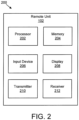
- Figure 2 depicts one embodiment of an apparatus 200 that may be used for uplink transmission blanking.
- the apparatus 200 includes one embodiment of the remote unit 102.
- the remote unit 102 may include a processor 202, a memory 204, an input device 206, a display 208, a transmitter 210, and a receiver 212.
- the input device 206 and the display 208 are combined into a single device, such as a touchscreen.
- the remote unit 102 may not include any input device 206 and/or display 208.
- the remote unit 102 may include one or more of the processor 202, the memory 204, the transmitter 210, and the receiver 212, and may not include the input device 206 and/or the display 208.
- the processor 202 may include any known controller capable of executing computer-readable instructions and/or capable of performing logical operations.
- the processor 202 may be a microcontroller, a microprocessor, a central processing unit ("CPU"), a graphics processing unit (“GPU”), an auxiliary processing unit, a field programmable gate array (“FPGA”), or similar programmable controller.
- the processor 202 executes instructions stored in the memory 204 to perform the methods and routines described herein.
- the processor 202 may determine one or more symbols of an uplink transmission to be blanked based on a signal.
- the processor 202 is communicatively coupled to the memory 204, the input device 206, the display 208, the transmitter 210, and the receiver 212.
- the memory 204 may be a computer readable storage medium.
- the memory 204 includes volatile computer storage media.
- the memory 204 may include a RAM, including dynamic RAM (“DRAM”), synchronous dynamic RAM (“SDRAM”), and/or static RAM (“SRAM”).
- the memory 204 includes non-volatile computer storage media.
- the memory 204 may include a hard disk drive, a flash memory, or any other suitable non-volatile computer storage device.
- the memory 204 includes both volatile and non-volatile computer storage media.
- the memory 204 stores data relating to an uplink transmission.
- the memory 204 also stores program code and related data, such as an operating system or other controller algorithms operating on the remote unit 102.
- the input device 206 may include any known computer input device including a touch panel, a button, a keyboard, a stylus, a microphone, or the like.
- the input device 206 may be integrated with the display 208, for example, as a touchscreen or similar touch-sensitive display.
- the input device 206 includes a touchscreen such that text may be input using a virtual keyboard displayed on the touchscreen and/or by handwriting on the touchscreen.
- the input device 206 includes two or more different devices, such as a keyboard and a touch panel.
- the display 208 may include any known electronically controllable display or display device.
- the display 208 may be designed to output visual, audible, and/or haptic signals.
- the display 208 includes an electronic display capable of outputting visual data to a user.
- the display 208 may include, but is not limited to, an LCD display, an LED display, an OLED display, a projector, or similar display device capable of outputting images, text, or the like to a user.
- the display 208 may include a wearable display such as a smart watch, smart glasses, a heads-up display, or the like.
- the display 208 may be a component of a smart phone, a personal digital assistant, a television, a table computer, a notebook (laptop) computer, a personal computer, a vehicle dashboard, or the like.
- the display 208 includes one or more speakers for producing sound.
- the display 208 may produce an audible alert or notification (e.g., a beep or chime).
- the display 208 includes one or more haptic devices for producing vibrations, motion, or other haptic feedback.
- all or portions of the display 208 may be integrated with the input device 206.
- the input device 206 and display 208 may form a touchscreen or similar touch-sensitive display.
- the display 208 may be located near the input device 206.
- the transmitter 210 is used to provide UL communication signals to the base unit 104 and the receiver 212 is used to receive DL communication signals from the base unit 104.
- the receiver 212 may be used to receive: a first signal from a base unit 104, wherein the first signal is used for indicating scheduling information for a first uplink transmission; and a third signal from the base unit 104, wherein the third signal is used for determining a first one or more symbols of the first uplink transmission to be blanked.
- the transmitter 210 may transmit the first uplink transmission to the base unit 104 with the first one or more symbols blanked.
- the remote unit 102 may have any suitable number of transmitters 210 and receivers 212.
- the transmitter 210 and the receiver 212 may be any suitable type of transmitters and receivers.
- the transmitter 210 and the receiver 212 may be part of a transceiver.
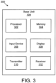
- Figure 3 depicts one embodiment of an apparatus 300 that may be used for uplink transmission blanking.
- the apparatus 300 includes one embodiment of the base unit 104.
- the base unit 104 may include a processor 302, a memory 304, an input device 306, a display 308, a transmitter 310, and a receiver 312.
- the processor 302, the memory 304, the input device 306, the display 308, the transmitter 310, and the receiver 312 may be substantially similar to the processor 202, the memory 204, the input device 206, the display 208, the transmitter 210, and the receiver 212 of the remote unit 102, respectively.
- the transmitter 310 is used to transmit: a first signal to a first remote unit 102, wherein the first signal is used to indicate scheduling information for the first remote unit 102 for a first uplink transmission; a second signal to a second remote unit 102, wherein the second signal is used to indicate a transmission resource for the second remote unit 102 for a second uplink transmission; and a third signal to the first remote unit 102, wherein the third signal is used for the first remote unit 102 to determine the first one or more symbols of the first uplink transmission to be blanked.
- the processor 302 determines the first one or more symbols of the first uplink transmission to be blanked.
- the receiver 312 receives the first uplink transmission from the first remote unit 102 with the first one or more symbols blanked.
- the base unit 104 may have any suitable number of transmitters 310 and receivers 312.
- the transmitter 310 and the receiver 312 may be any suitable type of transmitters and receivers.
- the transmitter 310 and the receiver 312 may be part of a transceiver.
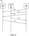
- Figure 4 illustrates one embodiment of communications 400 for uplink transmission blanking. Specifically, communications 400 between a first UE 402, a second UE 404, and a gNB 406 are illustrated.
- the first UE 402 may be an eMBB UE
- the second UE 404 may be a URLLC UE.
- the communications 400 may facilitate scheduling resources for eMBB and URLLC.
- a first communication 408 may include a first signal sent from the gNB 406 to the first UE 402 and used to indicate eMBB scheduling information for the first UE 402 for a first uplink transmission.
- a second communication 410 may include a second signal sent from the gNB 406 to the second UE 404 and used to indicate URLLC transmission information for the second UE 404 for a second uplink transmission.
- the second communication 410 may include RRC signaling or SIB signaling used to configure a resource pool for UL URLLC transmission, such as UL grant-free URLLC transmission.
- a third communication 412 may include a third signal sent from the gNB 406 to the first UE 402.
- the third signal may be used by the first UE 402 to determine a first one or more symbols of the first uplink transmission to blank.
- the third signal may, in one embodiment, include one bit in an UL grant that may be used for blank indication.
- the one bit may indicate to the first UE 402 to blank the first N symbols.
- the first UE 402 may implicitly derive the number N from the subcarrier spacing of eMBB. For example, N may be equal to 1 if the subcarrier spacing is 15 KHz and equal to 2 if the subcarrier spacing is 30 KHz.
- the third signal may, in another embodiment, include two bits to provide information for blanking symbols.
- the gNB 406 may select the value of the two-bit blank indication based on a cell coverage, a subcarrier spacing of eMBB, a timing offset between UL grant-free URLLC and UL eMBB, among other things.
- the third communication 412 is not used, and the first UE 402 uses the second communication 410 to determine a first one or more symbols of the first uplink transmission to blank. In certain embodiments, the first one or more symbols are blanked so that the first uplink transmission does not interfere with the second uplink transmission. In another embodiment, the third communication 412 is not used, and the first communication 408 includes information for the first UE 402 to determine a first one or more symbols of the first uplink transmission to blank.
- a fourth communication 414 includes the second uplink transmission transmitted from the second UE 404 to the gNB 406. Further, a fifth communication 416 includes the first uplink transmission with one or more blanked symbols so that the fifth communication 416 does not interfere with the fourth communication 414.
- the one or more blanked symbols may be blanked by puncturing or rate matching. In various embodiments, puncturing may be performed by removing certain parity bits after encoding data with an error-correction code.
- N symbols may be blanked. In various embodiments, N may be equal to 1 if the subcarrier spacing is 15 KHz and equal to 2 if the subcarrier spacing is 30 KHz.
- FIG. 5 is a schematic block diagram illustrating one embodiment of remote unit communications 500 using uplink transmission blanking. Specifically, a URLLC communication 502 transmitted from the second UE 404, and an eMBB communication 504 transmitted from the first UE 402, are illustrated.
- the URLLC communication 502 is transmitted in a first portion of a frequency domain 506 and a time domain 508.
- the eMBB communication 504 is transmitted in a second portion of the frequency domain 506 and the time domain 508. As illustrated, the URLLC communication 502 and the eMBB communication 504 overlap for a time period 510 in the time domain 508.
- one or more first symbols of the eMBB communication 504 may be blanked. Thereby, high reliability of the URLLC communication 502 may be obtained.
- the one or more first symbols of the eMBB communication 504 may be blanked by puncturing or rate matching.
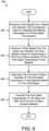
- Figure 6 is a schematic flow chart diagram illustrating one embodiment of a method 600 for uplink transmission blanking.
- the method 600 is performed by an apparatus, such as the remote unit 102.
- the method 600 may be performed by a processor executing program code, for example, a microcontroller, a microprocessor, a CPU, a GPU, an auxiliary processing unit, a FPGA, or the like.
- the method 600 may include receiving 602 a first signal from a base unit (e.g., the base unit 104). In such embodiments, the first signal may be used for indicating scheduling information for a first uplink transmission.
- the method 600 also includes receiving 604 a third signal from the base unit. In some embodiments, the third signal is used for determining a first one or more symbols of the first uplink transmission to be blanked. In one embodiment, the method 600 includes determining 606 the first one or more symbols of the first uplink transmission to be blanked based on the third signal. In various embodiments, the method 600 includes transmitting 608 the first uplink transmission to the base unit with the first one or more symbols blanked.
- the third signal indicates the first one or more symbols of the first uplink transmission to be blanked. In a further embodiment, the third signal indicates a number of symbols to be blanked at a beginning of the first uplink transmission. In certain non-claimed embodiments, the third signal is included in the first signal. In some embodiments, the third signal is used to indicate a transmission resource for a second uplink transmission.
- the first one or more symbols of the first uplink transmission are blanked in response to the first uplink transmission immediately following the transmission resource for the second uplink transmission. In the embodiments, a priority of the first uplink transmission is lower than a priority of the second uplink transmission. In one embodiment, the method 600 includes determining the first one or more symbols of the first uplink transmission to be blanked based on cell coverage, subcarrier spacing, timing offset between the first uplink transmission and the second uplink transmission, or some combination thereof. In a further embodiment, the first one or more symbols of the first uplink transmission are blanked by puncturing. In various embodiments, the first one or more symbols of the first uplink transmission are blanked by rate matching.
- Figure 7 is a schematic flow chart diagram illustrating one embodiment of a method 700 for uplink transmission blanking.
- the method 700 is performed by an apparatus, such as the base unit 104.
- the method 700 may be performed by a processor executing program code, for example, a microcontroller, a microprocessor, a CPU, a GPU, an auxiliary processing unit, a FPGA, or the like.
- the method 700 may include transmitting 702 a first signal to a first remote unit.
- the first signal is used to indicate scheduling information for the first remote unit for a first uplink transmission.
- the method 700 also includes transmitting 704 a second signal to a second remote unit.
- the second signal is used to indicate a transmission resource for the second remote unit for a second uplink transmission.
- the method 700 includes transmitting 706 a third signal to the first remote unit.
- the third signal is used for the first remote unit to determine the first one or more symbols of the first uplink transmission to be blanked.
- the method 700 also includes determining 708 the first one or more symbols of the first uplink transmission to be blanked.
- the method 700 includes receiving 710 the first uplink transmission from the first remote unit with the first one or more symbols blanked.
- the third signal indicates the first one or more symbols of the first uplink transmission to be blanked. In a further embodiment, the third signal indicates a number of symbols to be blanked at a beginning of the first uplink transmission. In certain non-claimed embodiments, the third signal is included in the first signal. In some embodiments, the method 700 includes determining the first one or more symbols of the first uplink transmission to be blanked based on cell coverage, subcarrier spacing, timing offset between the first uplink transmission and the second uplink transmission, or some combination thereof.
- the third signal is the same as the second signal.
- the first one or more symbols of the first uplink transmission are blanked in response to the first uplink transmission immediately following the second uplink transmission.
- a priority of the first uplink transmission is lower than a priority of the second uplink transmission.
- the first one or more symbols of the first uplink transmission are blanked by puncturing.
- the first one or more symbols of the first uplink transmission are blanked by rate matching.
Landscapes
- Engineering & Computer Science (AREA)
- Signal Processing (AREA)
- Computer Networks & Wireless Communication (AREA)
- Mobile Radio Communication Systems (AREA)
Claims (11)
- Einrichtung (200), umfassend:
einen Empfänger (212), der angeordnet ist zum:Empfangen eines ersten Signals von einer Basiseinheit, wobei das erste Signal verwendet wird, um Zeitplanungsinformationen für eine erste Uplink-Übertragung anzugeben; undEmpfangen eines dritten Signals von der Basiseinheit, wobei das dritte Signal verwendet wird, um eines oder mehrere erste auszublendende Symbole der ersten Uplink-Übertragung zu bestimmen, und wobei:das dritte Signal eine Übertragungsressource für eine zweite Uplink-Übertragung angibt;eine Priorität der ersten Uplink-Übertragung niedriger ist als eine Priorität der zweiten Uplink-Übertragung;die zweite Uplink-Übertragung der ersten Uplink-Übertragung vorausgeht; unddie erste Uplink-Übertragung mindestens teilweise die zweite Uplink-Übertragung überlappt;einen Prozessor (202), der dafür eingerichtet ist, das eine oder die mehreren ersten auszublendenden Symbole der ersten Uplink-Übertragung basierend auf dem dritten Signal zu bestimmen; undeinen Sender (210), der dafür eingerichtet ist, die erste Uplink-Übertragung an die Basiseinheit zu übertragen, wobei das eine oder die mehreren ersten Symbole ausgeblendet sind. - Einrichtung (200) nach Anspruch 1, wobei das dritte Signal das eine oder die mehreren ersten Symbole der ersten Uplink-Übertragung angibt, die auszublenden sind.
- Einrichtung (200) nach Anspruch 1, wobei das dritte Signal eine Anzahl von Symbolen angibt, die zu einem Beginn der ersten Uplink-Übertragung auszublenden sind.
- Einrichtung (200) nach Anspruch 1, wobei das eine oder die mehreren ersten Symbole der ersten Uplink-Übertragung als Reaktion auf die erste Uplink-Übertragung, die der Übertragungsressource für die zweite Uplink-Übertragung unmittelbar folgt, ausgeblendet werden.
- Einrichtung (200) nach Anspruch 1, wobei der Prozessor dafür eingerichtet ist, das eine oder die mehreren ersten auszublendenden Symbole der ersten Uplink-Übertragung basierend auf der Zellenabdeckung, Unterträgerabstand, Zeitversatz zwischen der ersten Uplink-Übertragung und der zweiten Uplink-Übertragung oder einer Kombination davon zu bestimmen.
- Einrichtung (200) nach Anspruch 1, wobei das erste oder die mehreren ersten Symbole der ersten Uplink-Übertragung durch Punktieren und/oder Ratenabgleich ausgeblendet werden.
- Verfahren (600) in einer Remote-Einheit, wobei das Verfahren umfasst:Empfangen (602) eines ersten Signals von einer Basiseinheit, wobei das erste Signal verwendet wird, um Zeitplanungsinformationen für eine erste Uplink-Übertragung anzugeben;Empfangen (604) eines dritten Signals von der Basiseinheit, wobei das dritte Signal verwendet wird, um eines oder mehrere erste auszublendende Symbole der ersten Uplink-Übertragung zu bestimmen, und wobei:das dritte Signal eine Übertragungsressource für eine zweite Uplink-Übertragung angibt;eine Priorität der ersten Uplink-Übertragung niedriger ist als eine Priorität der zweiten Uplink-Übertragung;die zweite Uplink-Übertragung der ersten Uplink-Übertragung vorausgeht; unddie erste Uplink-Übertragung mindestens teilweise die zweite Uplink-Übertragung überlappt;Bestimmen (606) des einen oder der mehreren ersten auszublendenden Symbole der ersten Uplink-Übertragung basierend auf dem dritten Signal; undÜbertragen (608) der ersten Uplink-Übertragung an die Basiseinheit, wobei das eine oder die mehreren ersten Symbole ausgeblendet sind.
- Verfahren (600) nach Anspruch 7, wobei das dritte Signal das eine oder die mehreren ersten Symbole der ersten Uplink-Übertragung angibt, die auszublenden sind.
- Verfahren (600) nach Anspruch 7, wobei das dritte Signal eine Anzahl von Symbolen angibt, die zu Beginn der ersten Uplink-Übertragung auszublenden sind.
- Einrichtung (300), umfassend:
einen Sender (310), der:ein erstes Signal an eine erste Remote-Einheit überträgt, wobei das erste Signal verwendet wird, um Zeitplanungsinformationen für die erste Remote-Einheit für eine erste Uplink-Übertragung anzugeben;Übertragen eines zweiten Signals an eine zweite Remote-Einheit, wobei das zweite Signal verwendet wird, um eine Übertragungsressource für die zweite Remote-Einheit für eine zweite Uplink-Übertragung anzugeben, wobei:eine Priorität der ersten Uplink-Übertragung niedriger ist als eine Priorität der zweiten Uplink-Übertragung;die zweite Uplink-Übertragung der ersten Uplink-Übertragung vorausgeht; unddie erste Uplink-Übertragung mindestens teilweise die zweite Uplink-Übertragung überlappt; undÜbertragen eines dritten Signals an die erste Remote-Einheit, wobei das dritte Signal eingerichtet ist, um der ersten Remote-Einheit das eine oder die mehreren ersten auszublendenden Symbole der ersten Uplink-Übertragung anzugeben und wobei das dritte Signal eine Übertragungsressource für eine zweite Uplink-Übertragung angibt;einen Prozessor (302), der das eine oder die mehreren ersten auszublendenden Symbole der ersten Uplink-Übertragung bestimmt; undeinen Empfänger (312), der die erste Uplink-Übertragung von der ersten Remote-Einheit empfängt, wobei das eine oder die mehreren ersten Symbole ausgeblendet sind. - Verfahren (700) in einer Basiseinheit, wobei das Verfahren umfasst:Übertragen (702) eines ersten Signals an eine erste Remote-Einheit, wobei das erste Signal verwendet wird, um Zeitplanungsinformationen für die erste Remote-Einheit für eine erste Uplink-Übertragung anzugeben;Übertragen (704) eines zweiten Signals an eine zweite Remote-Einheit, wobei das zweite Signal verwendet wird, um eine Übertragungsressource für die zweite Remote-Einheit für eine zweite Uplink-Übertragung anzugeben, wobei:eine Priorität der ersten Uplink-Übertragung niedriger ist als eine Priorität der zweiten Uplink-Übertragung;die zweite Uplink-Übertragung der ersten Uplink-Übertragung vorausgeht; unddie erste Uplink-Übertragung mindestens teilweise die zweite Uplink-Übertragung überlappt;Bestimmen (708) des einen oder der mehreren ersten auszublendenden Symbole der ersten Uplink-Übertragung;Übertragen (706) eines dritten Signals an die erste Remote-Einheit, wobei das dritte Signal eingerichtet ist, um er ersten Remote-Einheit das eine oder die mehreren ersten auszublendenden Symbole der ersten Uplink-Übertragung anzugeben und wobei das dritte Signal eine Übertragungsressource für eine zweite Uplink-Übertragung angibt; undEmpfangen (710) der ersten Uplink-Übertragung von der ersten Remote-Einheit, wobei das eine oder die mehreren ersten Symbole ausgeblendet sind.
Applications Claiming Priority (1)
| Application Number | Priority Date | Filing Date | Title |
|---|---|---|---|
| PCT/CN2017/070469 WO2018126447A1 (en) | 2017-01-06 | 2017-01-06 | Uplink transmission blanking |
Publications (4)
| Publication Number | Publication Date |
|---|---|
| EP3566543A1 EP3566543A1 (de) | 2019-11-13 |
| EP3566543A4 EP3566543A4 (de) | 2020-08-12 |
| EP3566543B1 true EP3566543B1 (de) | 2023-08-30 |
| EP3566543C0 EP3566543C0 (de) | 2023-08-30 |
Family
ID=62789028
Family Applications (1)
| Application Number | Title | Priority Date | Filing Date |
|---|---|---|---|
| EP17889970.4A Active EP3566543B1 (de) | 2017-01-06 | 2017-01-06 | Blanking einer uplink-übertragung |
Country Status (4)
| Country | Link |
|---|---|
| US (1) | US11283582B2 (de) |
| EP (1) | EP3566543B1 (de) |
| CN (1) | CN110121917B (de) |
| WO (1) | WO2018126447A1 (de) |
Families Citing this family (2)
| Publication number | Priority date | Publication date | Assignee | Title |
|---|---|---|---|---|
| US12317273B2 (en) * | 2017-03-31 | 2025-05-27 | Qualcomm Incorporated | Reliable delivery of system information |
| CN118612838A (zh) * | 2020-05-20 | 2024-09-06 | 高通股份有限公司 | 用于多面板天线上行链路传输的因面板而异的定时偏移 |
Citations (1)
| Publication number | Priority date | Publication date | Assignee | Title |
|---|---|---|---|---|
| US20160227557A1 (en) * | 2015-01-29 | 2016-08-04 | Qualcomm Incorporated | System and Methods for Providing a Transmission Skipping Policy to Improve Performance in a Multi-Subscriber Identity Module (SIM) Wireless Communication Device |
Family Cites Families (18)
| Publication number | Priority date | Publication date | Assignee | Title |
|---|---|---|---|---|
| US8879461B2 (en) * | 2008-12-01 | 2014-11-04 | Qualcomm Incorporated | Blank subframe uplink design |
| WO2010104338A2 (en) * | 2009-03-11 | 2010-09-16 | Samsung Electronics Co., Ltd. | Method and apparatus for allocating backhaul transmission resource in wireless communication system based on relay |
| CN103313402B (zh) * | 2012-03-16 | 2016-12-14 | 华为技术有限公司 | 一种上行资源分配的方法、装置及系统 |
| EP2856822B1 (de) | 2012-06-05 | 2019-01-02 | Telefonica S.A. | Verfahren zur funkressourcenverwendungsmeldung in einem lte-netzwerk und verwendungen davon zur interferenzreduktion und energieoptimierung |
| US9930678B2 (en) * | 2012-07-19 | 2018-03-27 | Qualcomm Incorporated | Multiplexing UEs with different TDD configurations and some techniques to mitigate UE-to-UE and base station-to-base station interference |
| CN103684713A (zh) * | 2012-09-26 | 2014-03-26 | 中国移动通信集团公司 | 一种载波聚合场景下上行数据信道重传的方法和系统 |
| KR101407094B1 (ko) * | 2012-10-31 | 2014-06-16 | 엘지전자 주식회사 | 상향링크 신호 전송 방법 및 장치 |
| US9813178B2 (en) * | 2012-11-26 | 2017-11-07 | Qualcomm Incorporated | Systems and methods for small cell uplink interference cancellation using cooperation between small cells |
| US9419700B2 (en) * | 2013-03-18 | 2016-08-16 | Electronics & Telecommunications Research Institute | Method for wireless communication based on relay and apparatus for the same |
| JP5899149B2 (ja) * | 2013-04-02 | 2016-04-06 | 株式会社Nttドコモ | 無線基地局及びユーザ端末 |
| EP4311127A3 (de) | 2013-12-04 | 2024-04-10 | Telefonaktiebolaget LM Ericsson (publ) | Uplink-subframe-kürzung in zeitduplex (tdd)-systemen |
| WO2015113499A1 (en) * | 2014-01-28 | 2015-08-06 | Mediatek Singapore Pte. Ltd. | Time domain multiplexing ul transmission on multiple serving cells for a mobile station with single transmitter |
| US20160119820A1 (en) * | 2014-10-28 | 2016-04-28 | Qualcomm Incorporated | Transmitting data through partially available time slots |
| EP3437430A4 (de) * | 2016-04-01 | 2019-10-23 | Qualcomm Incorporated | Handhabung von uplink-übertragungen in gegenwart von tune-aways |
| US20170325207A1 (en) * | 2016-05-06 | 2017-11-09 | Qualcomm Incorporated | Uplink Allocation Echoing |
| WO2017209670A1 (en) * | 2016-06-03 | 2017-12-07 | Telefonaktiebolaget Lm Ericsson (Publ) | Methods, network node and wireless communication device for handling of signals in a wireless communication network |
| US20180145818A1 (en) * | 2016-11-22 | 2018-05-24 | Samsung Electronics Co., Ltd. | Method and apparatus for multiplexing uplink channels in wireless cellular communication system |
| WO2018120112A1 (en) * | 2016-12-30 | 2018-07-05 | Telefonaktiebolaget Lm Ericsson (Publ) | Methods and devices for multi-connection transmission |
-
2017
- 2017-01-06 EP EP17889970.4A patent/EP3566543B1/de active Active
- 2017-01-06 US US16/476,243 patent/US11283582B2/en active Active
- 2017-01-06 WO PCT/CN2017/070469 patent/WO2018126447A1/en not_active Ceased
- 2017-01-06 CN CN201780081159.2A patent/CN110121917B/zh active Active
Patent Citations (1)
| Publication number | Priority date | Publication date | Assignee | Title |
|---|---|---|---|---|
| US20160227557A1 (en) * | 2015-01-29 | 2016-08-04 | Qualcomm Incorporated | System and Methods for Providing a Transmission Skipping Policy to Improve Performance in a Multi-Subscriber Identity Module (SIM) Wireless Communication Device |
Also Published As
| Publication number | Publication date |
|---|---|
| US11283582B2 (en) | 2022-03-22 |
| EP3566543A4 (de) | 2020-08-12 |
| US20190356461A1 (en) | 2019-11-21 |
| WO2018126447A1 (en) | 2018-07-12 |
| EP3566543C0 (de) | 2023-08-30 |
| CN110121917A (zh) | 2019-08-13 |
| EP3566543A1 (de) | 2019-11-13 |
| CN110121917B (zh) | 2022-11-08 |
Similar Documents
| Publication | Publication Date | Title |
|---|---|---|
| US11711706B2 (en) | Communication configuration selection | |
| EP3646649B1 (de) | Konfiguration eines demodulationsreferenzsignals | |
| US11991702B2 (en) | Resource reservation | |
| US10700824B2 (en) | Non-orthogonal communication | |
| EP3695672B1 (de) | Bestimmung eines übertragungsschemas | |
| EP4080980B1 (de) | Anzeige von planungsanfragen | |
| US11937307B2 (en) | Transmission beam indicating | |
| US11558858B2 (en) | Indication for a transmission scheme | |
| EP3619818B1 (de) | Bestimmung eines strahls zur räumlichen übertragung | |
| EP3662708B1 (de) | Berechtigungsfreie ressourcenzuweisung | |
| US11658774B2 (en) | Determining a resource field that carries feedback information | |
| EP3566543B1 (de) | Blanking einer uplink-übertragung | |
| EP3603296B1 (de) | Bestimmung von zeitfrequenzressourcen mithilfe von systemparametern | |
| EP3619847B1 (de) | Anzeige für einen transportblock |
Legal Events
| Date | Code | Title | Description |
|---|---|---|---|
| STAA | Information on the status of an ep patent application or granted ep patent |
Free format text: STATUS: THE INTERNATIONAL PUBLICATION HAS BEEN MADE |
|
| PUAI | Public reference made under article 153(3) epc to a published international application that has entered the european phase |
Free format text: ORIGINAL CODE: 0009012 |
|
| STAA | Information on the status of an ep patent application or granted ep patent |
Free format text: STATUS: REQUEST FOR EXAMINATION WAS MADE |
|
| 17P | Request for examination filed |
Effective date: 20190805 |
|
| AK | Designated contracting states |
Kind code of ref document: A1 Designated state(s): AL AT BE BG CH CY CZ DE DK EE ES FI FR GB GR HR HU IE IS IT LI LT LU LV MC MK MT NL NO PL PT RO RS SE SI SK SM TR |
|
| AX | Request for extension of the european patent |
Extension state: BA ME |
|
| DAV | Request for validation of the european patent (deleted) | ||
| DAX | Request for extension of the european patent (deleted) | ||
| A4 | Supplementary search report drawn up and despatched |
Effective date: 20200713 |
|
| RIC1 | Information provided on ipc code assigned before grant |
Ipc: H04L 5/00 20060101ALI20200707BHEP Ipc: H04W 72/12 20090101AFI20200707BHEP |
|
| STAA | Information on the status of an ep patent application or granted ep patent |
Free format text: STATUS: EXAMINATION IS IN PROGRESS |
|
| 17Q | First examination report despatched |
Effective date: 20220211 |
|
| REG | Reference to a national code |
Ref country code: DE Ref legal event code: R079 Ref document number: 602017073576 Country of ref document: DE Free format text: PREVIOUS MAIN CLASS: H04W0088000000 Ipc: H04W0072230000 Ref country code: DE Ref legal event code: R079 Free format text: PREVIOUS MAIN CLASS: H04W0088000000 Ipc: H04W0072230000 |
|
| GRAP | Despatch of communication of intention to grant a patent |
Free format text: ORIGINAL CODE: EPIDOSNIGR1 |
|
| STAA | Information on the status of an ep patent application or granted ep patent |
Free format text: STATUS: GRANT OF PATENT IS INTENDED |
|
| RIC1 | Information provided on ipc code assigned before grant |
Ipc: H04W 72/1268 20230101ALN20230213BHEP Ipc: H04L 5/00 20060101ALI20230213BHEP Ipc: H04W 72/23 20230101AFI20230213BHEP |
|
| RIC1 | Information provided on ipc code assigned before grant |
Ipc: H04W 72/1268 20230101ALN20230306BHEP Ipc: H04L 5/00 20060101ALI20230306BHEP Ipc: H04W 72/23 20230101AFI20230306BHEP |
|
| INTG | Intention to grant announced |
Effective date: 20230322 |
|
| GRAS | Grant fee paid |
Free format text: ORIGINAL CODE: EPIDOSNIGR3 |
|
| GRAA | (expected) grant |
Free format text: ORIGINAL CODE: 0009210 |
|
| STAA | Information on the status of an ep patent application or granted ep patent |
Free format text: STATUS: THE PATENT HAS BEEN GRANTED |
|
| AK | Designated contracting states |
Kind code of ref document: B1 Designated state(s): AL AT BE BG CH CY CZ DE DK EE ES FI FR GB GR HR HU IE IS IT LI LT LU LV MC MK MT NL NO PL PT RO RS SE SI SK SM TR |
|
| REG | Reference to a national code |
Ref country code: GB Ref legal event code: FG4D |
|
| REG | Reference to a national code |
Ref country code: CH Ref legal event code: EP |
|
| REG | Reference to a national code |
Ref country code: DE Ref legal event code: R096 Ref document number: 602017073576 Country of ref document: DE |
|
| REG | Reference to a national code |
Ref country code: IE Ref legal event code: FG4D |
|
| U01 | Request for unitary effect filed |
Effective date: 20230919 |
|
| U07 | Unitary effect registered |
Designated state(s): AT BE BG DE DK EE FI FR IT LT LU LV MT NL PT SE SI Effective date: 20230926 |
|
| PG25 | Lapsed in a contracting state [announced via postgrant information from national office to epo] |
Ref country code: GR Free format text: LAPSE BECAUSE OF FAILURE TO SUBMIT A TRANSLATION OF THE DESCRIPTION OR TO PAY THE FEE WITHIN THE PRESCRIBED TIME-LIMIT Effective date: 20231201 |
|
| PG25 | Lapsed in a contracting state [announced via postgrant information from national office to epo] |
Ref country code: IS Free format text: LAPSE BECAUSE OF FAILURE TO SUBMIT A TRANSLATION OF THE DESCRIPTION OR TO PAY THE FEE WITHIN THE PRESCRIBED TIME-LIMIT Effective date: 20231230 |
|
| PG25 | Lapsed in a contracting state [announced via postgrant information from national office to epo] |
Ref country code: RS Free format text: LAPSE BECAUSE OF FAILURE TO SUBMIT A TRANSLATION OF THE DESCRIPTION OR TO PAY THE FEE WITHIN THE PRESCRIBED TIME-LIMIT Effective date: 20230830 Ref country code: NO Free format text: LAPSE BECAUSE OF FAILURE TO SUBMIT A TRANSLATION OF THE DESCRIPTION OR TO PAY THE FEE WITHIN THE PRESCRIBED TIME-LIMIT Effective date: 20231130 Ref country code: IS Free format text: LAPSE BECAUSE OF FAILURE TO SUBMIT A TRANSLATION OF THE DESCRIPTION OR TO PAY THE FEE WITHIN THE PRESCRIBED TIME-LIMIT Effective date: 20231230 Ref country code: HR Free format text: LAPSE BECAUSE OF FAILURE TO SUBMIT A TRANSLATION OF THE DESCRIPTION OR TO PAY THE FEE WITHIN THE PRESCRIBED TIME-LIMIT Effective date: 20230830 Ref country code: GR Free format text: LAPSE BECAUSE OF FAILURE TO SUBMIT A TRANSLATION OF THE DESCRIPTION OR TO PAY THE FEE WITHIN THE PRESCRIBED TIME-LIMIT Effective date: 20231201 |
|
| PG25 | Lapsed in a contracting state [announced via postgrant information from national office to epo] |
Ref country code: PL Free format text: LAPSE BECAUSE OF FAILURE TO SUBMIT A TRANSLATION OF THE DESCRIPTION OR TO PAY THE FEE WITHIN THE PRESCRIBED TIME-LIMIT Effective date: 20230830 |
|
| U21 | Renewal fee for the european patent with unitary effect paid with additional fee |
Year of fee payment: 8 Effective date: 20240229 |
|
| PG25 | Lapsed in a contracting state [announced via postgrant information from national office to epo] |
Ref country code: ES Free format text: LAPSE BECAUSE OF FAILURE TO SUBMIT A TRANSLATION OF THE DESCRIPTION OR TO PAY THE FEE WITHIN THE PRESCRIBED TIME-LIMIT Effective date: 20230830 |
|
| PG25 | Lapsed in a contracting state [announced via postgrant information from national office to epo] |
Ref country code: SM Free format text: LAPSE BECAUSE OF FAILURE TO SUBMIT A TRANSLATION OF THE DESCRIPTION OR TO PAY THE FEE WITHIN THE PRESCRIBED TIME-LIMIT Effective date: 20230830 Ref country code: RO Free format text: LAPSE BECAUSE OF FAILURE TO SUBMIT A TRANSLATION OF THE DESCRIPTION OR TO PAY THE FEE WITHIN THE PRESCRIBED TIME-LIMIT Effective date: 20230830 Ref country code: ES Free format text: LAPSE BECAUSE OF FAILURE TO SUBMIT A TRANSLATION OF THE DESCRIPTION OR TO PAY THE FEE WITHIN THE PRESCRIBED TIME-LIMIT Effective date: 20230830 Ref country code: CZ Free format text: LAPSE BECAUSE OF FAILURE TO SUBMIT A TRANSLATION OF THE DESCRIPTION OR TO PAY THE FEE WITHIN THE PRESCRIBED TIME-LIMIT Effective date: 20230830 Ref country code: SK Free format text: LAPSE BECAUSE OF FAILURE TO SUBMIT A TRANSLATION OF THE DESCRIPTION OR TO PAY THE FEE WITHIN THE PRESCRIBED TIME-LIMIT Effective date: 20230830 |
|
| REG | Reference to a national code |
Ref country code: DE Ref legal event code: R097 Ref document number: 602017073576 Country of ref document: DE |
|
| PLBE | No opposition filed within time limit |
Free format text: ORIGINAL CODE: 0009261 |
|
| STAA | Information on the status of an ep patent application or granted ep patent |
Free format text: STATUS: NO OPPOSITION FILED WITHIN TIME LIMIT |
|
| 26N | No opposition filed |
Effective date: 20240603 |
|
| PG25 | Lapsed in a contracting state [announced via postgrant information from national office to epo] |
Ref country code: MC Free format text: LAPSE BECAUSE OF FAILURE TO SUBMIT A TRANSLATION OF THE DESCRIPTION OR TO PAY THE FEE WITHIN THE PRESCRIBED TIME-LIMIT Effective date: 20230830 |
|
| PG25 | Lapsed in a contracting state [announced via postgrant information from national office to epo] |
Ref country code: MC Free format text: LAPSE BECAUSE OF FAILURE TO SUBMIT A TRANSLATION OF THE DESCRIPTION OR TO PAY THE FEE WITHIN THE PRESCRIBED TIME-LIMIT Effective date: 20230830 |
|
| REG | Reference to a national code |
Ref country code: CH Ref legal event code: PL |
|
| PG25 | Lapsed in a contracting state [announced via postgrant information from national office to epo] |
Ref country code: CH Free format text: LAPSE BECAUSE OF NON-PAYMENT OF DUE FEES Effective date: 20240131 |
|
| PG25 | Lapsed in a contracting state [announced via postgrant information from national office to epo] |
Ref country code: CH Free format text: LAPSE BECAUSE OF NON-PAYMENT OF DUE FEES Effective date: 20240131 |
|
| PG25 | Lapsed in a contracting state [announced via postgrant information from national office to epo] |
Ref country code: IE Free format text: LAPSE BECAUSE OF NON-PAYMENT OF DUE FEES Effective date: 20240106 |
|
| PG25 | Lapsed in a contracting state [announced via postgrant information from national office to epo] |
Ref country code: IE Free format text: LAPSE BECAUSE OF NON-PAYMENT OF DUE FEES Effective date: 20240106 |
|
| U20 | Renewal fee for the european patent with unitary effect paid |
Year of fee payment: 9 Effective date: 20250127 |
|
| PG25 | Lapsed in a contracting state [announced via postgrant information from national office to epo] |
Ref country code: CY Free format text: LAPSE BECAUSE OF FAILURE TO SUBMIT A TRANSLATION OF THE DESCRIPTION OR TO PAY THE FEE WITHIN THE PRESCRIBED TIME-LIMIT; INVALID AB INITIO Effective date: 20170106 |
|
| PG25 | Lapsed in a contracting state [announced via postgrant information from national office to epo] |
Ref country code: HU Free format text: LAPSE BECAUSE OF FAILURE TO SUBMIT A TRANSLATION OF THE DESCRIPTION OR TO PAY THE FEE WITHIN THE PRESCRIBED TIME-LIMIT; INVALID AB INITIO Effective date: 20170106 |
|
| PG25 | Lapsed in a contracting state [announced via postgrant information from national office to epo] |
Ref country code: TR Free format text: LAPSE BECAUSE OF FAILURE TO SUBMIT A TRANSLATION OF THE DESCRIPTION OR TO PAY THE FEE WITHIN THE PRESCRIBED TIME-LIMIT Effective date: 20230830 |
|
| U20 | Renewal fee for the european patent with unitary effect paid |
Year of fee payment: 10 Effective date: 20260126 |
|
| PGFP | Annual fee paid to national office [announced via postgrant information from national office to epo] |
Ref country code: GB Payment date: 20260126 Year of fee payment: 10 |