EP3566729A1 - Hämodialysemaschine mit einem flüssigkeits-durchfluss-messsystem und zugehöriges funktionsverfahren - Google Patents
Hämodialysemaschine mit einem flüssigkeits-durchfluss-messsystem und zugehöriges funktionsverfahren Download PDFInfo
- Publication number
- EP3566729A1 EP3566729A1 EP19173936.6A EP19173936A EP3566729A1 EP 3566729 A1 EP3566729 A1 EP 3566729A1 EP 19173936 A EP19173936 A EP 19173936A EP 3566729 A1 EP3566729 A1 EP 3566729A1
- Authority
- EP
- European Patent Office
- Prior art keywords
- resistive
- value
- heat
- differential
- duct
- Prior art date
- Legal status (The legal status is an assumption and is not a legal conclusion. Google has not performed a legal analysis and makes no representation as to the accuracy of the status listed.)
- Granted
Links
Images


Classifications
-
- A—HUMAN NECESSITIES
- A61—MEDICAL OR VETERINARY SCIENCE; HYGIENE
- A61M—DEVICES FOR INTRODUCING MEDIA INTO, OR ONTO, THE BODY; DEVICES FOR TRANSDUCING BODY MEDIA OR FOR TAKING MEDIA FROM THE BODY; DEVICES FOR PRODUCING OR ENDING SLEEP OR STUPOR
- A61M1/00—Suction or pumping devices for medical purposes; Devices for carrying-off, for treatment of, or for carrying-over, body-liquids; Drainage systems
- A61M1/36—Other treatment of blood in a by-pass of the natural circulatory system, e.g. temperature adaptation, irradiation ; Extra-corporeal blood circuits
- A61M1/3621—Extra-corporeal blood circuits
- A61M1/3663—Flow rate transducers; Flow integrators
-
- G—PHYSICS
- G01—MEASURING; TESTING
- G01F—MEASURING VOLUME, VOLUME FLOW, MASS FLOW OR LIQUID LEVEL; METERING BY VOLUME
- G01F1/00—Measuring the volume flow or mass flow of fluid or fluent solid material wherein the fluid passes through a meter in a continuous flow
- G01F1/68—Measuring the volume flow or mass flow of fluid or fluent solid material wherein the fluid passes through a meter in a continuous flow by using thermal effects
- G01F1/684—Structural arrangements; Mounting of elements, e.g. in relation to fluid flow
- G01F1/688—Structural arrangements; Mounting of elements, e.g. in relation to fluid flow using a particular type of heating, cooling or sensing element
- G01F1/69—Structural arrangements; Mounting of elements, e.g. in relation to fluid flow using a particular type of heating, cooling or sensing element of resistive type
-
- G—PHYSICS
- G01—MEASURING; TESTING
- G01F—MEASURING VOLUME, VOLUME FLOW, MASS FLOW OR LIQUID LEVEL; METERING BY VOLUME
- G01F1/00—Measuring the volume flow or mass flow of fluid or fluent solid material wherein the fluid passes through a meter in a continuous flow
- G01F1/68—Measuring the volume flow or mass flow of fluid or fluent solid material wherein the fluid passes through a meter in a continuous flow by using thermal effects
- G01F1/696—Circuits therefor, e.g. constant-current flow meters
-
- A—HUMAN NECESSITIES
- A61—MEDICAL OR VETERINARY SCIENCE; HYGIENE
- A61M—DEVICES FOR INTRODUCING MEDIA INTO, OR ONTO, THE BODY; DEVICES FOR TRANSDUCING BODY MEDIA OR FOR TAKING MEDIA FROM THE BODY; DEVICES FOR PRODUCING OR ENDING SLEEP OR STUPOR
- A61M2205/00—General characteristics of the apparatus
- A61M2205/33—Controlling, regulating or measuring
- A61M2205/3331—Pressure; Flow
- A61M2205/3334—Measuring or controlling the flow rate
Definitions
- the present invention concerns a haemodialysis machine provided with a system for measuring the flowrate of a liquid and to the operating method thereof.
- the present invention also concerns determining the flowrate differential between a first and a second liquid that flow through two respective ducts or channels of a haemodialysis machine so as to be able to advantageously determine the weight loss in a haemodialysis treatment performed with the haemodialysis machine.
- haemodialysis machines generally comprise a haematic circuit that is provided with a filter basically consisting of a blood compartment and a dialyser compartment, mutually separated by a semi-permeable membrane and through which, in use, the blood to be treated and, respectively, a dialysing liquid, generally flowing in the opposite direction, can pass.
- a filter basically consisting of a blood compartment and a dialyser compartment, mutually separated by a semi-permeable membrane and through which, in use, the blood to be treated and, respectively, a dialysing liquid, generally flowing in the opposite direction, can pass.
- An arterial channel and a venous channel are connected with an inlet and with an outlet of the blood compartment, respectively, while an inflowing dialysis channel and an outflowing dialysis channel are connected with an inlet and an outlet of the dialyser compartment, respectively.
- the unwanted particles contained in the blood migrate from the blood compartment to the dialyser compartment through the membrane due to the passage of a part of the liquid contained in the blood towards the dialyser compartment.
- a "weight loss" of the patient must be measured with extreme accuracy to avoid significant side effects, such as, collapse and cramps.
- Some known systems/apparatus for measuring weight loss mounted in haemodialysis machines have the technical drawback of having footprints and production costs that have a non-negligible impact on the footprint and respectively the total cost of the haemodialysis machine.
- the Applicant has designed a haemodialysis machine provided with a weight loss measurement system comprising a differential flowmeter operating substantially based on the operating principal of a thermal anemometer.
- Said differential flowmeter is described, for example, in the European patent application EP 2 946 179 A1 filed by the Applicant, and basically comprises two channels adapted for respective haematic fluids to pass there through, and a pair of PTC (Positive Temperature Coefficient) heat-resistive sensors, each arranged in a respective channel.
- each heat-resistive sensor is electrically heated so that its temperature reaches a value greater than a pre-set temperature of the fluid circulating in the relative channel.
- the flow of the fluid in the channel causes the dissipation of heat from the thermistor that determines a decrease in temperature and hence in the resistance of the sensor itself.
- the decrease in resistance caused by the fluids on the related heat-resistive sensors is subsequently processed by a differential electronic device that determines the differential flowrate of the fluids that flow through the two channels based on the resistance variation determined.
- the differential flowmeter described above is particularly simple, inexpensive and accurate, the Applicant has carried out research in order to further increase the precision and sensitivity in determining the flowrate of a liquid in one or more channels and/or the differential flowrate of the liquids that pass through two channels.
- the aim of the present invention is therefore to provide a solution that enables at least the objectives indicated above to be achieved.
- a haemodialysis machine (1) comprising a haematic circuit provided with a dialyser filter and one or more ducts that are connected to said dialyser filter and are adapted to allow respective liquids to pass there through, and a measurement system provided with a measurement circuit comprising one or more heat-resistive components associated with respective ducts, the haemodialysis machine being characterised in that said measurement system is configured to: supply an electric current having an alternation of first and second pre-set current values to said measurement circuit; said first current values being sized so that said heat-resistive components transmit a first quantity of negligible minimum heat towards the liquid that passes through the relative duct, said second current values being sized so that said heat-resistive components transmit a second quantity of heat significantly greater than said first quantity of heat, towards the liquid that passes through the relative duct; determine at least a first resistive value and a second resistive value indicative of a resistance variation on said at least one heat-res
- the measurement system comprises a measuring apparatus provided with: current generator means connected to a heat-resistive component associated with a first duct for supplying the latter with said electric current, voltage measuring means for measuring a first voltage value of said heat-resistive component when the first current value passes through the latter and for measuring a second voltage value of said heat-resistive component, when said second current value passes through the latter, and calculation means configured to: calculate said first resistive value and said second resistive value based on said first voltage value and first current value and, respectively, on said second voltage value and second current value, calculate the differential resistive value based on the first and second resistive values, and calculate the flowrate of the liquid passing through the first duct based on said differential resistive value.
- the measurement system comprises a second measuring apparatus provided with: current generator means connected to a heat-resistive component associated with a second duct for supplying the latter with said electric current, voltage measuring means for measuring a first voltage value of said heat-resistive component when the first current value passes through the latter and measuring a second voltage value of said heat-resistive component when said second current value passes through the latter, and calculation means configured so as to: determine said first resistive value and said second resistive value based on said first voltage value and said first current value and, respectively, on said second voltage value and second current value, determine the differential resistive value based on the first and second resistive values, and determine the flowrate of the liquid passing through the second duct based on the differential resistive value.
- the measurement system comprises a measuring apparatus provided with: a measurement branch comprising two heat-resistive components connected together in series and associated with a first duct and a second duct, respectively, current generator means connected to the measurement branch for supplying the latter with said electric current; voltage measurement means for measuring on each of said two heat-resistive components: a first voltage value and a second voltage value when said first and respectively second current values pass through the measurement branch; calculation means configured to: determine, for each of the two heat-resistive components, a differential resistive value based on the difference between the relative second and first resistive values.
- said calculation means are configured so as to determine the flowrate differential of the liquids passing through the first and the second ducts, based on said differential resistive values.
- the calculation means are configured so as to: calculate a first magnitude based on the difference between the two differential resistive values of the two ducts; determine the flowrate differential between the two ducts based on said first magnitude.
- the calculation means are configured so as to determine, for each of the two heat-resistive components, the flowrate of the liquid passing through the relative duct, based on the relative differential resistive value.
- the measurement system further comprises processing means configured so as to: receive a first flowrate of the liquid passing through the first duct, receive a second flowrate of the liquid passing through the second duct, determine the flowrate differential between the liquid passing through the first duct and the liquid passing through the second duct as a function of the first and second flowrates.
- the measurement circuit of said measuring apparatus comprises a Wheatstone bridge measurement circuit provided with a first heat-resistive component associated with a first duct, and a second heat-resistive component associated with a second duct.
- the measuring apparatus comprises current generator means for supplying said current to a first terminal of said bridge, voltage measuring means for measuring a first voltage value between two nodes of said bridge when the first current value passes through said first terminal and measuring a second voltage value between two nodes of said bridge when the second current value passes through said first terminal, and calculation means configured so as to: determine said first resistive value and said second resistive value based on said first voltage value and said first current value and respectively on said second voltage value and said second current value; determine the differential resistive value based on the first and second resistive values, and determine the flowrate differential between the liquid passing through the first duct and the liquid passing through the second duct, based on the differential resistive value.
- said electric current is a square wave current, in which said first and second current values are approximately constant.
- the aim is also achieved by the present invention as it relates to an operating method of a haemodialysis machine comprising: a haematic circuit provided with a dialyser filter and one or more ducts that are connected to said dialyser filter and are adapted to allow respective liquids to pass there through, and a measurement circuit comprising one or more heat-resistive components associated with one or more ducts; said method being characterised in that it comprises the steps of: supplying an electric current having alternation of first and second pre-set current values to said measurement circuit; said first current values being sized so that said heat-resistive components transmit a first quantity of negligible minimum heat towards the liquid that passes through the relative duct, said second current values being sized so that said heat-resistive components transmit a second quantity of heat significantly greater than said first quantity of heat to the liquid that passes through the relative duct; determining at least a first resistive value and a second resistive value indicative of a resistance variation on said at least one heat-resistive component caused
- the measurement circuit comprises at least a heat-resistive component associated with a relative first duct for supplying the latter with said electric current; the method comprising the steps of: supplying, by means of current generator means, said electric current to said heat-resistive component, measuring, through voltage measuring means, a first voltage value of said heat-resistive component when the first current value passes through the latter, measuring a second voltage value of said heat-resistive component when said second current value passes through the latter, calculating said first resistive value and said second resistive value based on said first voltage value and said first current value and respectively on said second voltage value and said second current value; calculating a differential resistive value based on the first and second resistive values, and calculating the flowrate of the liquid passing through the first duct based on the differential resistive value.
- said measurement circuit comprises a second measuring apparatus provided with: current generator means connected to a heat-resistive component associated with a second duct for supplying the latter with said electric current, voltage measuring means for measuring a first voltage value of said heat-resistive component when the first current value passes through the latter and measuring a second voltage value of said heat-resistive component when said second current value passes through the latter, the method comprising the steps of: calculating said first resistive value and said second resistive value based on said first voltage value and said first current value and, respectively, on said second voltage value and second current value, calculating the differential resistive value based on the first and second resistive values, calculating the flowrate of the liquid passing through the second duct based on the differential resistive value.
- the measurement system comprises a measuring apparatus provided with: a measurement branch comprising two heat-resistive components connected together in series and associated with a first and a second duct, respectively, current generator means connected to the measurement branch for supplying the latter with said electric current; voltage measuring means for measuring, on each of said two heat-resistive components: a first voltage value and a second voltage value when said first and second current values respectively pass through the measurement branch; the method comprising the step of determining, for each of the two heat-resistive components, a differential resistive value based on the difference between the relative second and first resistive values.
- the method further comprises the step of: determining the flowrate differential of the liquids passing through the first and the second ducts based on said differential resistive values.
- the method comprises: calculating a first magnitude based on the difference between the two differential resistive values of the two ducts; determining the flowrate differential between the two ducts based on said first magnitude.
- the method comprises the step of determining, for each of the two heat-resistive components, the flowrate of the liquid passing through the relative duct based on the relative differential resistive value.
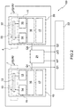
- the number 1 shows as a whole, in a simplified and schematic manner (with the aim of increasing understanding of the present invention), an example of a haemodialysis machine, that comprises a haematic circuit 2 provided with a dialyser filter 3, which can, for example, consist of a blood compartment and of a dialyser compartment, preferably separated from each other by a semi-permeable membrane through which, in use, the blood to be treated and, respectively, a dialysing liquid, preferably flowing in the opposite direction, can pass.
- a dialyser filter 3 can, for example, consist of a blood compartment and of a dialyser compartment, preferably separated from each other by a semi-permeable membrane through which, in use, the blood to be treated and, respectively, a dialysing liquid, preferably flowing in the opposite direction, can pass.
- the dialyser filter 3 can be supplied, on the one side (in a first inlet), with a dialysing liquid, i.e., a dialysate, through a duct 4, and on the other side (in a second inlet), with a haematic liquid, i.e., the arterial blood that flows through a duct 5, preferably as a result of the action of a pump 6, for example a peristaltic pump.
- a dialysing liquid i.e., a dialysate
- a haematic liquid i.e., the arterial blood that flows through a duct 5
- a pump 6 for example a peristaltic pump.
- the exchange of impurities between blood and dialysate takes place in the dialyser filter 3 according to a known process, which is not the subject matter of the present invention and shall not be further described, except to specify that in the example illustrated, the so-called "dirty" dialysate (containing impurities) flows out via the filter 3 flowing through a duct 7 (outlet), while the treated blood (filtered to remove the impurities) is reintroduced into the human body BD through a duct 8 (outlet) connected to the patient's vein.
- the haemodialysis machine 1 can also be provided with a pressure measuring device 9, which, in the example illustrated, is arranged along the duct 8 to measure the blood pressure, preferably the venous pressure and detect the presence of air in the duct 5.
- a pressure measuring device 9 which, in the example illustrated, is arranged along the duct 8 to measure the blood pressure, preferably the venous pressure and detect the presence of air in the duct 5.
- the haemodialysis machine 1 further comprises an electric/electronic measurement system 100 provided with at least one measuring apparatus 10 adapted to measure the flowrate of a liquid that passes through a duct of the haematic circuit 2.
- the liquid in which the flowrate is measured by the measuring apparatus 10 corresponds to the dialysate circulating through the duct 7.
- the measuring apparatus 10 produced according to the present invention can be associated with/connected to any duct present in the haemodialysis machine 1.
- the measuring apparatus 10 produced according to the present invention can be associated with the duct 4, or alternatively to the ducts 5 or 8 to measure the flowrate of the blood therein.
- the measuring apparatus 10 of the measurement system 100 basically comprises an electric/electronic measurement circuit 11, which is provided with at least an electric heat-resistive component 12.
- the electric heat-resistive component 12 can advantageously comprise, for example, a heat sensor, preferably ad anemometer, the electric heat-resistive (sensitive) component of which is used both as heat sink sensor and as temperature sensor. It is understood that the electric heat-resistive component 12 is used for temperature compensation of the fluid so that the flowrate is independent from the temperature of the fluid.
- the electric heat-resistive component 12 can comprise a PTC (Positive Temperature Coefficient) resistor or any similar electric/electronic thermistor component.
- PTC Physical Temperature Coefficient
- the electric heat-resistive component 12 can be associated with/coupled to/arranged in the duct 7 to be able to transmit and/or receive heat, directly or indirectly, to/from the liquid that passes through the duct 7.
- the electric heat-resistive component 12 can be arranged inside a measuring channel 13 hydraulically connected with the duct 7.
- the electric heat-resistive component 12 is advantageously wetted by the liquid being measured (in contact with the liquid) and varies its resistance as a function of the temperature and of the flowrate of this liquid.
- the measuring channel 13 can advantageously be included in the measuring device 10.
- the present invention can provide the measuring channel 13 separate from the measuring device 10.
- the measuring channel 13 can correspond to a portion/stretch of the duct 7.
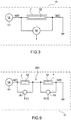
- the measurement circuit 11 can preferably comprise a current generator device 14 adapted to supply a current Is(t) to the heat-resistive component 12.
- the current generator device 14 can generate an approximately square wave current Is(t). For each period t, the current Is(t) generated can alternate a first low current value ISL during a first half-period tL, and a high second current value ISH, greater than the first current value ISL, during the second half-period tH.
- the two current values ISL and ISH can be approximately constant in the respective half-periods tL and tH.
- the first current value ISL can be fixed (calibrated) to cause the transmission of a negligible quantity of heat by the heat-resistive component 12 towards the relative liquid.
- negligible means the transmission of a quantity of heat that does not cause a significant disturbance of the temperature of the liquid.
- the first current value ISL is such so as to cause heating through the Joule effect of the electric heat-resistive component 12, which however is extremely limited or negligible, i.e., is insufficient to cause a significant increase in the temperature of the liquid wets the heat-resistive component 12, a higher increase, for example lower than approximately 0.01°C.
- a first current value ISL having a value comprised between around 0.5 ⁇ 10-3 Ampere and around 2 ⁇ 10-3 Ampere, preferably 1 ⁇ 10-3 Ampere does not significantly disturb the temperature of the liquid.
- the resistance of the heat-resistive component 12 in idle condition it could be in the order of 100 Ohm.
- the heat-resistive component 12 could advantageously be a platinum resistor.
- the second current value ISH can be fixed (calibrated) to cause the transmission of a substantial quantity of heat by the heat-resistive component 12 towards the relative liquid.
- the second current value ISH is such so as to cause a (significant) pre-set heating through the Joule effect on the electric heat-resistive component 12 capable of causing an increase in the temperature of the liquid that wets the heat-resistive component 12, in the order of a few degrees, for example between around five degrees and around eight degrees.
- the second current value ISH could advantageously be comprised between around 9 ⁇ 10 -3 Ampere and around 15 ⁇ 10 -3 Ampere, preferably 10 ⁇ 10 -3 Ampere.
- the measurement circuit 11 can further comprise a voltage measuring device 15, which is electrically connected to the heat-resistive component 12, for example at the terminals thereof.
- the voltage measuring device 15 is configured so as to measure the electrical voltages, designated by VL and VH, at the terminals of the resistive component 12 during the half-period t1L and respectively the half-period t1H ( Fig. 5 ).
- the measuring apparatus 10 can further comprise a calculation device 16 configured so as to implement the calculation operations described in detail below, for determining the flowrate of the liquid.
- the calculation device 16 can be programmed/configured to:
- the Applicant has found that calculation of the flowrate Q1 based on the differential resistive value Rd performed as described above, advantageously allows a decrease in the error introduced by the temperature of the liquid in calculation of the flowrate. In other words, calculation of the flowrate Q1 based on the differential resistive value Rd makes it possible to obtain a strong temperature compensation, i.e., to eliminate the dependency of the convective flow on the temperature of the fluid.
- the Applicant has in fact found that the following occurs in the measuring apparatus 10.
- the resistance R of the heat-resistive component 12 in contact with a liquid varies as a function of different parameters, such as: the flowrate of the liquid Q1, the current Is(t) and the temperature of the liquid tF, i.e.:
- the Joule effect of the resistive component 12 is negligible and does not cause temperature variations tF in the liquid or, vice versa, the aforesaid resistive component 12 is substantially at the temperature of this liquid.
- the relation g) is indicative of the fact that the differential resistive value Rd depends substantially on the flowrate Q1, as also ⁇ t depends on the flowrate Q1. Therefore, the Applicant has found that a direct relation exists between differential resistive value Rd and the flowrate Q1 that does not depend on the temperature of the liquid.
- the measuring apparatus 10 can be provided with a memory device 17 that stores/contains, for example, one or more calculation tables.
- At least one stored calculation table can contain, for example, a plurality of differential resistive values Rd(i) and a plurality of flowrates Q1(i).
- Each differential resistive value Rd(i) of the calculation table can be associated with a respective flowrate Q1(i) value.
- the flowrates Q1(i) and the relative differential resistive values Rd(i) contained in the calculation table can advantageously be determined in a calibration/testing step of the measuring apparatus 10.
- the calibration step used to determine the calculation table can provide for: supplying the square wave current Is(t) in the resistive circuit 12 according to the two pre-set current values ISL and ISH; imparting a plurality of pre-set flowrates Q1(i) of liquid passing through the duct 7; calculating for each flowrate Q1(i) the relative differential resistive value Rd(i) based on what has been described above; and storing the flowrates Q1(i) imparted and the relative differential resistive values Rd(i) calculated.
- the calculation table can be used by the calculation device 16 as "calculation function" to determine the flowrate Q1 of the liquid based on the differential resistive value Rd(i) calculated.
- the measuring apparatus 10 can be configured to continuously reiterate the operations described above so as to determine, instant by instant, the differential resistive value Rd(i) and, based on this, the flowrate Q1. In this way, the measuring apparatus 10 can determine the variation of the flowrate Q1 over time.
- the measuring apparatus 10 can be configured to repeat the following operations at pre-set measurement instants: sample the voltages VL and VH at the instant of measurement, calculate the resistances RL and RH based on the voltages VL and VH sampled, determine the differential resistive values Rd based on the difference between the resistances RL and RH calculated, and thus determine the flowrate Q1 in the measurement instant as a function of the differential resistive value Rd calculated.
- the measurement system 100 can also advantageously be adapted to determine the flowrate differential ⁇ Q between the flowrate Q1 between the liquid that passes through the duct 7 and the flowrate Q2 of the liquid that passes through another duct, such as the duct 4 in the haemodialysis machine 1 shown in Fig. 1 .
- the measurement system 100 can be provided with another measuring apparatus, designated below with 20.
- the measuring apparatus 20 can be functionally and structurally identical to the measuring apparatus 10 described above, the component parts of which will be designated with the same reference numbers that indicate corresponding parts of the measuring apparatus 10.
- the measuring apparatus 20 is associated with the duct 4, is configured to determine the flowrate Q2 of the relative dialysing liquid supplied, at inlet, to the dialyser filter 3.
- the measuring apparatus 20 is configured so as to calculate the flowrate Q2, carrying out the same operations described above implemented by the measuring apparatus 10 for calculations.
- the electronic processing device 21 can also be configured to determine a value indicative of the weight loss KP based on the differential flowrate ⁇ Q between the dialysing liquids flowing, at inlet and outlet, of the dialyser filter 3.
- the haemodialysis machine 1 can be provided with a user interface device 22, for example a display mounted in a control panel or the like, to notify the user of a series of information associated with the haemodialysis process.
- the information notified to the user can be, for example: the flowrates of the liquids Q1 and Q2 that pass through the relative ducts, the differential flowrate ⁇ Q, and/or the weight loss Kp (total mass of liquids removed from the patient during the dialysis session).
- the measurement system 100 advantageously performs the function of a differential flowmeter.
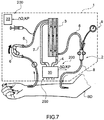
- the embodiment illustrated in Fig. 7 relates to a measurement system 200, which is similar to the measurement system 100 shown in Fig. 1 and the component parts of which will be designated, where possible, with the same reference numbers that designate corresponding parts of the measurement system 100.
- the measurement system 200 comprises a measuring apparatus 30, which differs from the measuring apparatus 10 in that: the measurement circuit 11 comprises a measurement branch 201 comprising, in turn, two heat-resistive components 12 connected together in series and associated with two respective ducts.
- the heat-resistive components 12 are preferably associated with the duct 7 and respectively with the duct 4.
- the measuring apparatus 30 further comprises the current generator device 14 that is connected to the measurement branch 201 for supplying the electric current Is(t) to the latter.
- the measurement circuit 11 of the measuring apparatus 30 further comprises two voltage measuring devices 15, which are respectively connected to the heat-resistive components 12 to measure the voltages V1 and V2 at the terminals of the latter.
- the measuring apparatus 30 is configured to perform the following operations.
- the current generator 14 supplies the preferably square wave current Is(t) to the measurement branch 201; the voltage measuring devices 15 measure, during each first half-period tL, the voltages VL1 and VL2 present at the terminals of the two heat-resistive components 12 and, during each second half-period tH, the voltages VH1 and VH2 present at the terminals of the two heat-resistive components 12.
- the calculation device 16 is configured to perform the following operations:
- the flowrates Q1 and Q2 can be determined by the calculation device 16 through relative calculation functions F1(Rd1) and F2(Rd2). It is also understood that, in the same way as the measurement system 100 described above, the calculation functions F1(Rd1) and F2(Rd2) can be associated with respective calculation tables relative to the two ducts, preferably the ducts 4 and 7.
- the calculation tables can contain a plurality of differential resistive values Rd(i) and a plurality of flowrates Q(i). In the calculation tables, each differential resistive value Rd(i) can preferably be associated with a respective flowrate value Q(i).
- the flowrates Q(i) and the relative differential resistive values Rd(i) can advantageously be determined during the calibration/testing step of the measurement system 200.
- the electronic processing device 21 can be configured so as to: receive the two flowrates Q1 and Q2 from the calculation device 16; calculate the differential ⁇ Q between the flowrates Q1 and Q2 of the liquid passing through the two ducts 7 and 4.
- the electronic processing device 21 can be further configured to calculate the weight loss Kp based on the flowrates Q1 and Q2.
- the operation of the measuring apparatus 30 is not limited to calculation of the differential ⁇ Q based on the two flowrates Q1 and Q2 calculated but can include other calculation methods.
- the measuring apparatus 30 could advantageously be configured to calculate the differential flowrate ⁇ Q based directly on the differential resistive values Rd(i) hence without performing the intermediate calculation of the flowrates Q1 and Q2, with consequent decrease in errors in calculation of the differential flowrate ⁇ Q.
- the calculation device 16 can be configured so as to:
- the calculation function FD can be defined, for example, through a calibration table.
- the calibration table can be stored in the storage device 17 of the measurement system 200 and contain a plurality of resistive values RD(i) and a plurality of flowrate differentials ⁇ Q(i).
- the calibration table can be structured so that each resistive value RD(i) can preferably be associated with a respective flowrate differential ⁇ Q(i).
- the electronic processing device 21 of the system 200 can calculate the weight loss Kp based on the flowrate differential ⁇ Q(i).
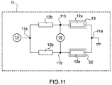
- Fig. 10 relates to a measurement system 300, which is similar to the measurement system 100 shown in Fig. 1 and the component parts of which will be designated, where possible, with the same reference numbers that designate corresponding parts of the measurement system 100.
- the measuring apparatus 30 differs from the measuring apparatus 10 in that the relative measurement circuit 11 comprises a Wheatstone bridge measurement circuit preferably supplied by current.
- the Wheatstone bridge measurement circuit comprises a terminal 11a connected to the current generator device 14 to receive the current Is(t), a terminal 11a connected to a reference terminal GND, preferably a terminal placed at a ground potential, and two measurement nodes 11b between which the voltage measurement device 15 is connected.
- the Wheatstone bridge further comprises four resistive components arranged on four respective circuit branches connected respectively between a terminal 11a and a measurement node 11b.
- two resistive components 12a of the Wheatstone bridge comprise two respective PTC temperature sensor components, while the other two resistive components 12b comprise resistors having a pre-set (fixed) resistance.
- the two resistive components 12a are arranged inside respective measurement channels 13 and 32 associated with the ducts 4 and 7 so as to be wetted in use by the two liquids subject to the measurement and are thus adapted to vary the relative resistances as a function of the temperatures tf1 and tf2 and of the flowrates Q1 and Q2 of the liquids.
- the voltage measurement device 15 can be configured so as to determine a voltage indicative of a condition of unbalance of the bridge relative to a pre-set condition of balance of the bridge.
- the measuring apparatus 30 of the measurement system 300 is configured to perform the following operations.
- the current generator 14 supplies the Wheatstone bridge, for example the node 11a, with the preferably square wave current Is(t) having in the half-periods tL and tH, the first ISL and respectively the second current value ISH ( Fig. 3 ), and the voltage measurement device 15 measures the voltage VdL between the nodes 11b during each first half-period tL, and the voltage VdH present between the nodes 11b during each second half-period tH.
- the measuring apparatus 30 of the measurement system 300 is further configured so that the calculation device 16 determines a first resistive value RdL associated with the first half-period tL.
- the measuring apparatus 30 is further configured so that the calculation device 16 determines a second resistive value RdH associated with the second half-period tH.
- the measuring apparatus 30 of the measurement system 300 is further configured so that the calculation device 16 determines the differential ⁇ Q between the flowrate Q1 of the liquid that passes through the measuring channel 13 and the flowrate Q2 of the liquid that passes through the measuring channel 32 based on the differential resistive value Rd calculated.
- the measuring apparatus 30 of the system 300 can also be provided with a storage device 17 containing at least one calculation table that contains a plurality of differential resistive values Rd(i) and a plurality of flowrate differentials ⁇ Q(i).
- each differential resistive value Rd(i) can be associated with a respective flowrate differential ⁇ Q(i).
- the numerical values contained in the table can advantageously be determined by performing calibrations/tests implemented on the measuring apparatus 30 which provide for: supplying the square wave current Is(t) having the first and second pre-set values ISL and ISH to the Wheatstone bridge, imparting the pre-set flowrates Q(i) of liquid in the two channels 13 and 32 according to pre-set flowrate differentials ⁇ Q(i), calculating for each flowrate differential ⁇ Q(i) the relative differential resistive value Rd(i), and storing the flowrate differential ⁇ Q(i) and the corresponding differential resistive value Rd(i) in the calibration table.
- the haemodialysis machine described above has various advantages.
- the measurement system describe above according to the different embodiments has high measurement precision, greater in particular, for example, in machines provided with CCA (Constant Current Anemometer) measurement systems in which both the temperature and the flowrate are measured.
- CCA Constant Current Anemometer
- Constant Current Anemometers supply a constant current to the measurement circuit, perform temperature measurement with a dedicated sensor, and calculate the flowrate based on the temperature measured.
- the present system differs from conventional Constant Current Anemometers as, besides supplying the circuit with a square wave current, it does not provide for direct measurement of the temperature to calculate the flowrate and thus eliminates from the latter the errors associated with temperature measurement. In other words, as the system described above does not measure the temperature directly, it is not subject to the relative measurement errors.
- the measurement system and in particular the temperature compensation of the measurement itself, due to: use of the same sensitive element used both to compensate the temperature of the fluid and to measure the flowrate of the latter; calculation of the flowrate compensated through the differential calculation of the resistance Rd without necessarily measuring/calculating the temperature of the liquid is in fact advantageously strong, as it greatly decreases the uncertainties introduced in the measurement above all due to a partial cancellation of systemic errors, both during calibration and measurement.
Landscapes
- Health & Medical Sciences (AREA)
- Physics & Mathematics (AREA)
- Fluid Mechanics (AREA)
- General Physics & Mathematics (AREA)
- Vascular Medicine (AREA)
- Heart & Thoracic Surgery (AREA)
- Biomedical Technology (AREA)
- Anesthesiology (AREA)
- Engineering & Computer Science (AREA)
- Hematology (AREA)
- Life Sciences & Earth Sciences (AREA)
- Animal Behavior & Ethology (AREA)
- General Health & Medical Sciences (AREA)
- Public Health (AREA)
- Veterinary Medicine (AREA)
- Cardiology (AREA)
- Measuring Volume Flow (AREA)
- External Artificial Organs (AREA)
Applications Claiming Priority (1)
| Application Number | Priority Date | Filing Date | Title |
|---|---|---|---|
| IT102018000005288A IT201800005288A1 (it) | 2018-05-11 | 2018-05-11 | Macchina per emodialisi provvista di un sistema di misura della portata di un liquido e relativo metodo di funzionamento |
Publications (2)
| Publication Number | Publication Date |
|---|---|
| EP3566729A1 true EP3566729A1 (de) | 2019-11-13 |
| EP3566729B1 EP3566729B1 (de) | 2021-03-24 |
Family
ID=63312224
Family Applications (1)
| Application Number | Title | Priority Date | Filing Date |
|---|---|---|---|
| EP19173936.6A Active EP3566729B1 (de) | 2018-05-11 | 2019-05-10 | Hämodialysemaschine mit einem flüssigkeits-durchfluss-messsystem und zugehöriges funktionsverfahren |
Country Status (3)
| Country | Link |
|---|---|
| EP (1) | EP3566729B1 (de) |
| ES (1) | ES2868235T3 (de) |
| IT (1) | IT201800005288A1 (de) |
Cited By (2)
| Publication number | Priority date | Publication date | Assignee | Title |
|---|---|---|---|---|
| IT202100000521A1 (it) | 2021-01-13 | 2022-07-13 | Medica S P A | Dispositivo per diuresi artificiale |
| CN115768498A (zh) * | 2020-03-31 | 2023-03-07 | 麦迪卡股份公司 | 设置有包括光学传感器的测量系统的血液过滤机器 |
Citations (4)
| Publication number | Priority date | Publication date | Assignee | Title |
|---|---|---|---|---|
| GB1385595A (en) * | 1971-07-26 | 1975-02-26 | Hoffmann La Roche | Method and apparatus for pressure and flow measurement |
| US5247434A (en) * | 1991-04-19 | 1993-09-21 | Althin Medical, Inc. | Method and apparatus for kidney dialysis |
| EP1343576A2 (de) * | 2000-10-19 | 2003-09-17 | Nephros, Inc. | Verfahren und vorrichtung zur erzeugung eines sterilien infusionsfluids |
| WO2014111908A1 (en) * | 2013-01-21 | 2014-07-24 | Medica S.P.A. | Differential flow-meter for measuring the ponderal decrease in hemodialysis treatments |
-
2018
- 2018-05-11 IT IT102018000005288A patent/IT201800005288A1/it unknown
-
2019
- 2019-05-10 EP EP19173936.6A patent/EP3566729B1/de active Active
- 2019-05-10 ES ES19173936T patent/ES2868235T3/es active Active
Patent Citations (5)
| Publication number | Priority date | Publication date | Assignee | Title |
|---|---|---|---|---|
| GB1385595A (en) * | 1971-07-26 | 1975-02-26 | Hoffmann La Roche | Method and apparatus for pressure and flow measurement |
| US5247434A (en) * | 1991-04-19 | 1993-09-21 | Althin Medical, Inc. | Method and apparatus for kidney dialysis |
| EP1343576A2 (de) * | 2000-10-19 | 2003-09-17 | Nephros, Inc. | Verfahren und vorrichtung zur erzeugung eines sterilien infusionsfluids |
| WO2014111908A1 (en) * | 2013-01-21 | 2014-07-24 | Medica S.P.A. | Differential flow-meter for measuring the ponderal decrease in hemodialysis treatments |
| EP2946179A1 (de) | 2013-01-21 | 2015-11-25 | Medica S.p.A. | Differenzialdurchflussmesser zur messung des gewichtsverlustes bei hämodialysebehandlungen |
Cited By (4)
| Publication number | Priority date | Publication date | Assignee | Title |
|---|---|---|---|---|
| CN115768498A (zh) * | 2020-03-31 | 2023-03-07 | 麦迪卡股份公司 | 设置有包括光学传感器的测量系统的血液过滤机器 |
| US12343463B2 (en) | 2020-03-31 | 2025-07-01 | Medica S.P.A. | Blood filtering machine provided with a measuring system comprising optical sensors |
| IT202100000521A1 (it) | 2021-01-13 | 2022-07-13 | Medica S P A | Dispositivo per diuresi artificiale |
| EP4029541A1 (de) | 2021-01-13 | 2022-07-20 | Medica S.p.A. | Messvorrichtung und künstliche diuresevorrichtung |
Also Published As
| Publication number | Publication date |
|---|---|
| EP3566729B1 (de) | 2021-03-24 |
| ES2868235T3 (es) | 2021-10-21 |
| IT201800005288A1 (it) | 2019-11-11 |
Similar Documents
| Publication | Publication Date | Title |
|---|---|---|
| EP0547025B2 (de) | Verfahren zur Bestimmung der Konzentration einer Substanz in Blut oder der dialysanz eines Dialysators | |
| CA1193662A (en) | Hematocrit measuring instrument | |
| JP2885373B2 (ja) | 人工腎臓 | |
| JP5378391B2 (ja) | 流体流速センサ及び動作方法 | |
| EP3566729B1 (de) | Hämodialysemaschine mit einem flüssigkeits-durchfluss-messsystem und zugehöriges funktionsverfahren | |
| US10533883B2 (en) | Thermal, flow measuring device with diagnostic function | |
| SE510513C2 (sv) | Förfarande och anordning för att mäta ultrafiltreringsvolymen i en dialysmaskin samt förfarande för kalibrering av anordningen | |
| EP3004855B1 (de) | Zelle zur messung der leitfähigkeit einer flüssigkeit | |
| US20180143051A1 (en) | Airflow sensor with thermal conductivity & diffusivity sensing | |
| KR890017716A (ko) | 미소차 온도센서를 사용한 계측 및 감시시스템 | |
| CN105122019B (zh) | 用于测量血液透析治疗的重量损失的差分流量计 | |
| CN107866159B (zh) | 用于预混合透析液的方法和装置 | |
| Febriyanti et al. | Calibration and testing of sensors used during dialysate preparation in hemodialysis machine | |
| CN107635596B (zh) | 血液治疗仪 | |
| US3425278A (en) | Flowmeter | |
| JP2964186B2 (ja) | 熱式流量計 | |
| JP2771949B2 (ja) | 熱式流量センサ | |
| DE4004513A1 (de) | Verfahren und anordnung zum mengenmessenden aufheizen eines stroemenden fluids, insbesondere einer fluessigkeit | |
| JP7381004B2 (ja) | 測定装置 | |
| SU1136083A1 (ru) | Термоанемометрическа измерительна система | |
| PL247197B1 (pl) | Sposób pomiaru prędkości przepływu płynu czujnikiem termoanemometrycznym | |
| SU691760A1 (ru) | Термоанемометрическа система | |
| SU102296A1 (ru) | Устройство дл автоматического контрол и регулировани соотношени концентрации двух растворенных в воде компонентов | |
| CS203746B1 (cs) | Zařízení pro měření extrémně nízkých průtoků plynů | |
| JPS632626B2 (de) |
Legal Events
| Date | Code | Title | Description |
|---|---|---|---|
| PUAI | Public reference made under article 153(3) epc to a published international application that has entered the european phase |
Free format text: ORIGINAL CODE: 0009012 |
|
| STAA | Information on the status of an ep patent application or granted ep patent |
Free format text: STATUS: THE APPLICATION HAS BEEN PUBLISHED |
|
| AK | Designated contracting states |
Kind code of ref document: A1 Designated state(s): AL AT BE BG CH CY CZ DE DK EE ES FI FR GB GR HR HU IE IS IT LI LT LU LV MC MK MT NL NO PL PT RO RS SE SI SK SM TR |
|
| AX | Request for extension of the european patent |
Extension state: BA ME |
|
| STAA | Information on the status of an ep patent application or granted ep patent |
Free format text: STATUS: REQUEST FOR EXAMINATION WAS MADE |
|
| 17P | Request for examination filed |
Effective date: 20200513 |
|
| RBV | Designated contracting states (corrected) |
Designated state(s): AL AT BE BG CH CY CZ DE DK EE ES FI FR GB GR HR HU IE IS IT LI LT LU LV MC MK MT NL NO PL PT RO RS SE SI SK SM TR |
|
| GRAP | Despatch of communication of intention to grant a patent |
Free format text: ORIGINAL CODE: EPIDOSNIGR1 |
|
| STAA | Information on the status of an ep patent application or granted ep patent |
Free format text: STATUS: GRANT OF PATENT IS INTENDED |
|
| RIC1 | Information provided on ipc code assigned before grant |
Ipc: A61M 1/36 20060101AFI20200918BHEP |
|
| INTG | Intention to grant announced |
Effective date: 20201012 |
|
| GRAS | Grant fee paid |
Free format text: ORIGINAL CODE: EPIDOSNIGR3 |
|
| GRAA | (expected) grant |
Free format text: ORIGINAL CODE: 0009210 |
|
| STAA | Information on the status of an ep patent application or granted ep patent |
Free format text: STATUS: THE PATENT HAS BEEN GRANTED |
|
| AK | Designated contracting states |
Kind code of ref document: B1 Designated state(s): AL AT BE BG CH CY CZ DE DK EE ES FI FR GB GR HR HU IE IS IT LI LT LU LV MC MK MT NL NO PL PT RO RS SE SI SK SM TR |
|
| REG | Reference to a national code |
Ref country code: GB Ref legal event code: FG4D |
|
| REG | Reference to a national code |
Ref country code: CH Ref legal event code: EP |
|
| REG | Reference to a national code |
Ref country code: NL Ref legal event code: FP Ref country code: IE Ref legal event code: FG4D |
|
| REG | Reference to a national code |
Ref country code: DE Ref legal event code: R096 Ref document number: 602019003341 Country of ref document: DE Ref country code: AT Ref legal event code: REF Ref document number: 1373826 Country of ref document: AT Kind code of ref document: T Effective date: 20210415 |
|
| REG | Reference to a national code |
Ref country code: SE Ref legal event code: TRGR |
|
| REG | Reference to a national code |
Ref country code: LT Ref legal event code: MG9D |
|
| PG25 | Lapsed in a contracting state [announced via postgrant information from national office to epo] |
Ref country code: NO Free format text: LAPSE BECAUSE OF FAILURE TO SUBMIT A TRANSLATION OF THE DESCRIPTION OR TO PAY THE FEE WITHIN THE PRESCRIBED TIME-LIMIT Effective date: 20210624 Ref country code: FI Free format text: LAPSE BECAUSE OF FAILURE TO SUBMIT A TRANSLATION OF THE DESCRIPTION OR TO PAY THE FEE WITHIN THE PRESCRIBED TIME-LIMIT Effective date: 20210324 Ref country code: HR Free format text: LAPSE BECAUSE OF FAILURE TO SUBMIT A TRANSLATION OF THE DESCRIPTION OR TO PAY THE FEE WITHIN THE PRESCRIBED TIME-LIMIT Effective date: 20210324 Ref country code: GR Free format text: LAPSE BECAUSE OF FAILURE TO SUBMIT A TRANSLATION OF THE DESCRIPTION OR TO PAY THE FEE WITHIN THE PRESCRIBED TIME-LIMIT Effective date: 20210625 Ref country code: BG Free format text: LAPSE BECAUSE OF FAILURE TO SUBMIT A TRANSLATION OF THE DESCRIPTION OR TO PAY THE FEE WITHIN THE PRESCRIBED TIME-LIMIT Effective date: 20210624 |
|
| PG25 | Lapsed in a contracting state [announced via postgrant information from national office to epo] |
Ref country code: LV Free format text: LAPSE BECAUSE OF FAILURE TO SUBMIT A TRANSLATION OF THE DESCRIPTION OR TO PAY THE FEE WITHIN THE PRESCRIBED TIME-LIMIT Effective date: 20210324 Ref country code: RS Free format text: LAPSE BECAUSE OF FAILURE TO SUBMIT A TRANSLATION OF THE DESCRIPTION OR TO PAY THE FEE WITHIN THE PRESCRIBED TIME-LIMIT Effective date: 20210324 |
|
| REG | Reference to a national code |
Ref country code: AT Ref legal event code: MK05 Ref document number: 1373826 Country of ref document: AT Kind code of ref document: T Effective date: 20210324 |
|
| REG | Reference to a national code |
Ref country code: ES Ref legal event code: FG2A Ref document number: 2868235 Country of ref document: ES Kind code of ref document: T3 Effective date: 20211021 |
|
| PG25 | Lapsed in a contracting state [announced via postgrant information from national office to epo] |
Ref country code: SM Free format text: LAPSE BECAUSE OF FAILURE TO SUBMIT A TRANSLATION OF THE DESCRIPTION OR TO PAY THE FEE WITHIN THE PRESCRIBED TIME-LIMIT Effective date: 20210324 Ref country code: AT Free format text: LAPSE BECAUSE OF FAILURE TO SUBMIT A TRANSLATION OF THE DESCRIPTION OR TO PAY THE FEE WITHIN THE PRESCRIBED TIME-LIMIT Effective date: 20210324 Ref country code: EE Free format text: LAPSE BECAUSE OF FAILURE TO SUBMIT A TRANSLATION OF THE DESCRIPTION OR TO PAY THE FEE WITHIN THE PRESCRIBED TIME-LIMIT Effective date: 20210324 Ref country code: CZ Free format text: LAPSE BECAUSE OF FAILURE TO SUBMIT A TRANSLATION OF THE DESCRIPTION OR TO PAY THE FEE WITHIN THE PRESCRIBED TIME-LIMIT Effective date: 20210324 Ref country code: LT Free format text: LAPSE BECAUSE OF FAILURE TO SUBMIT A TRANSLATION OF THE DESCRIPTION OR TO PAY THE FEE WITHIN THE PRESCRIBED TIME-LIMIT Effective date: 20210324 |
|
| PG25 | Lapsed in a contracting state [announced via postgrant information from national office to epo] |
Ref country code: IS Free format text: LAPSE BECAUSE OF FAILURE TO SUBMIT A TRANSLATION OF THE DESCRIPTION OR TO PAY THE FEE WITHIN THE PRESCRIBED TIME-LIMIT Effective date: 20210724 Ref country code: PL Free format text: LAPSE BECAUSE OF FAILURE TO SUBMIT A TRANSLATION OF THE DESCRIPTION OR TO PAY THE FEE WITHIN THE PRESCRIBED TIME-LIMIT Effective date: 20210324 Ref country code: PT Free format text: LAPSE BECAUSE OF FAILURE TO SUBMIT A TRANSLATION OF THE DESCRIPTION OR TO PAY THE FEE WITHIN THE PRESCRIBED TIME-LIMIT Effective date: 20210726 Ref country code: RO Free format text: LAPSE BECAUSE OF FAILURE TO SUBMIT A TRANSLATION OF THE DESCRIPTION OR TO PAY THE FEE WITHIN THE PRESCRIBED TIME-LIMIT Effective date: 20210324 Ref country code: SK Free format text: LAPSE BECAUSE OF FAILURE TO SUBMIT A TRANSLATION OF THE DESCRIPTION OR TO PAY THE FEE WITHIN THE PRESCRIBED TIME-LIMIT Effective date: 20210324 |
|
| REG | Reference to a national code |
Ref country code: DE Ref legal event code: R097 Ref document number: 602019003341 Country of ref document: DE |
|
| PG25 | Lapsed in a contracting state [announced via postgrant information from national office to epo] |
Ref country code: LU Free format text: LAPSE BECAUSE OF NON-PAYMENT OF DUE FEES Effective date: 20210510 Ref country code: DK Free format text: LAPSE BECAUSE OF FAILURE TO SUBMIT A TRANSLATION OF THE DESCRIPTION OR TO PAY THE FEE WITHIN THE PRESCRIBED TIME-LIMIT Effective date: 20210324 Ref country code: AL Free format text: LAPSE BECAUSE OF FAILURE TO SUBMIT A TRANSLATION OF THE DESCRIPTION OR TO PAY THE FEE WITHIN THE PRESCRIBED TIME-LIMIT Effective date: 20210324 Ref country code: MC Free format text: LAPSE BECAUSE OF FAILURE TO SUBMIT A TRANSLATION OF THE DESCRIPTION OR TO PAY THE FEE WITHIN THE PRESCRIBED TIME-LIMIT Effective date: 20210324 |
|
| PLBE | No opposition filed within time limit |
Free format text: ORIGINAL CODE: 0009261 |
|
| STAA | Information on the status of an ep patent application or granted ep patent |
Free format text: STATUS: NO OPPOSITION FILED WITHIN TIME LIMIT |
|
| REG | Reference to a national code |
Ref country code: BE Ref legal event code: MM Effective date: 20210531 |
|
| PG25 | Lapsed in a contracting state [announced via postgrant information from national office to epo] |
Ref country code: SI Free format text: LAPSE BECAUSE OF FAILURE TO SUBMIT A TRANSLATION OF THE DESCRIPTION OR TO PAY THE FEE WITHIN THE PRESCRIBED TIME-LIMIT Effective date: 20210324 |
|
| 26N | No opposition filed |
Effective date: 20220104 |
|
| PG25 | Lapsed in a contracting state [announced via postgrant information from national office to epo] |
Ref country code: IE Free format text: LAPSE BECAUSE OF NON-PAYMENT OF DUE FEES Effective date: 20210510 |
|
| PG25 | Lapsed in a contracting state [announced via postgrant information from national office to epo] |
Ref country code: IS Free format text: LAPSE BECAUSE OF FAILURE TO SUBMIT A TRANSLATION OF THE DESCRIPTION OR TO PAY THE FEE WITHIN THE PRESCRIBED TIME-LIMIT Effective date: 20210724 |
|
| PG25 | Lapsed in a contracting state [announced via postgrant information from national office to epo] |
Ref country code: BE Free format text: LAPSE BECAUSE OF NON-PAYMENT OF DUE FEES Effective date: 20210531 |
|
| REG | Reference to a national code |
Ref country code: CH Ref legal event code: PL |
|
| PG25 | Lapsed in a contracting state [announced via postgrant information from national office to epo] |
Ref country code: LI Free format text: LAPSE BECAUSE OF NON-PAYMENT OF DUE FEES Effective date: 20220531 Ref country code: CH Free format text: LAPSE BECAUSE OF NON-PAYMENT OF DUE FEES Effective date: 20220531 |
|
| P01 | Opt-out of the competence of the unified patent court (upc) registered |
Effective date: 20230331 |
|
| PG25 | Lapsed in a contracting state [announced via postgrant information from national office to epo] |
Ref country code: CY Free format text: LAPSE BECAUSE OF FAILURE TO SUBMIT A TRANSLATION OF THE DESCRIPTION OR TO PAY THE FEE WITHIN THE PRESCRIBED TIME-LIMIT Effective date: 20210324 |
|
| PG25 | Lapsed in a contracting state [announced via postgrant information from national office to epo] |
Ref country code: HU Free format text: LAPSE BECAUSE OF FAILURE TO SUBMIT A TRANSLATION OF THE DESCRIPTION OR TO PAY THE FEE WITHIN THE PRESCRIBED TIME-LIMIT; INVALID AB INITIO Effective date: 20190510 |
|
| GBPC | Gb: european patent ceased through non-payment of renewal fee |
Effective date: 20230510 |
|
| PG25 | Lapsed in a contracting state [announced via postgrant information from national office to epo] |
Ref country code: MK Free format text: LAPSE BECAUSE OF FAILURE TO SUBMIT A TRANSLATION OF THE DESCRIPTION OR TO PAY THE FEE WITHIN THE PRESCRIBED TIME-LIMIT Effective date: 20210324 Ref country code: GB Free format text: LAPSE BECAUSE OF NON-PAYMENT OF DUE FEES Effective date: 20230510 |
|
| PG25 | Lapsed in a contracting state [announced via postgrant information from national office to epo] |
Ref country code: MT Free format text: LAPSE BECAUSE OF FAILURE TO SUBMIT A TRANSLATION OF THE DESCRIPTION OR TO PAY THE FEE WITHIN THE PRESCRIBED TIME-LIMIT Effective date: 20210324 |
|
| PGFP | Annual fee paid to national office [announced via postgrant information from national office to epo] |
Ref country code: NL Payment date: 20250526 Year of fee payment: 7 |
|
| PGFP | Annual fee paid to national office [announced via postgrant information from national office to epo] |
Ref country code: DE Payment date: 20250528 Year of fee payment: 7 |
|
| PGFP | Annual fee paid to national office [announced via postgrant information from national office to epo] |
Ref country code: ES Payment date: 20250611 Year of fee payment: 7 |
|
| PGFP | Annual fee paid to national office [announced via postgrant information from national office to epo] |
Ref country code: IT Payment date: 20250507 Year of fee payment: 7 |
|
| PGFP | Annual fee paid to national office [announced via postgrant information from national office to epo] |
Ref country code: FR Payment date: 20250526 Year of fee payment: 7 |
|
| PGFP | Annual fee paid to national office [announced via postgrant information from national office to epo] |
Ref country code: SE Payment date: 20250526 Year of fee payment: 7 |
|
| PG25 | Lapsed in a contracting state [announced via postgrant information from national office to epo] |
Ref country code: TR Free format text: LAPSE BECAUSE OF FAILURE TO SUBMIT A TRANSLATION OF THE DESCRIPTION OR TO PAY THE FEE WITHIN THE PRESCRIBED TIME-LIMIT Effective date: 20210324 |