EP3566735B1 - Coussinet de nez de masque respiratoire et masque respiratoire - Google Patents
Coussinet de nez de masque respiratoire et masque respiratoire Download PDFInfo
- Publication number
- EP3566735B1 EP3566735B1 EP17890306.8A EP17890306A EP3566735B1 EP 3566735 B1 EP3566735 B1 EP 3566735B1 EP 17890306 A EP17890306 A EP 17890306A EP 3566735 B1 EP3566735 B1 EP 3566735B1
- Authority
- EP
- European Patent Office
- Prior art keywords
- nasal
- nasal pad
- frame
- gas flow
- flow passage
- Prior art date
- Legal status (The legal status is an assumption and is not a legal conclusion. Google has not performed a legal analysis and makes no representation as to the accuracy of the status listed.)
- Active
Links
Images


Classifications
-
- A—HUMAN NECESSITIES
- A61—MEDICAL OR VETERINARY SCIENCE; HYGIENE
- A61M—DEVICES FOR INTRODUCING MEDIA INTO, OR ONTO, THE BODY; DEVICES FOR TRANSDUCING BODY MEDIA OR FOR TAKING MEDIA FROM THE BODY; DEVICES FOR PRODUCING OR ENDING SLEEP OR STUPOR
- A61M16/00—Devices for influencing the respiratory system of patients by gas treatment, e.g. ventilators; Tracheal tubes
- A61M16/06—Respiratory or anaesthetic masks
- A61M16/0666—Nasal cannulas or tubing
- A61M16/0672—Nasal cannula assemblies for oxygen therapy
-
- A—HUMAN NECESSITIES
- A61—MEDICAL OR VETERINARY SCIENCE; HYGIENE
- A61M—DEVICES FOR INTRODUCING MEDIA INTO, OR ONTO, THE BODY; DEVICES FOR TRANSDUCING BODY MEDIA OR FOR TAKING MEDIA FROM THE BODY; DEVICES FOR PRODUCING OR ENDING SLEEP OR STUPOR
- A61M16/00—Devices for influencing the respiratory system of patients by gas treatment, e.g. ventilators; Tracheal tubes
- A61M16/06—Respiratory or anaesthetic masks
- A61M16/0683—Holding devices therefor
-
- A—HUMAN NECESSITIES
- A61—MEDICAL OR VETERINARY SCIENCE; HYGIENE
- A61M—DEVICES FOR INTRODUCING MEDIA INTO, OR ONTO, THE BODY; DEVICES FOR TRANSDUCING BODY MEDIA OR FOR TAKING MEDIA FROM THE BODY; DEVICES FOR PRODUCING OR ENDING SLEEP OR STUPOR
- A61M16/00—Devices for influencing the respiratory system of patients by gas treatment, e.g. ventilators; Tracheal tubes
- A61M16/0003—Accessories therefor, e.g. sensors, vibrators, negative pressure
-
- A—HUMAN NECESSITIES
- A61—MEDICAL OR VETERINARY SCIENCE; HYGIENE
- A61M—DEVICES FOR INTRODUCING MEDIA INTO, OR ONTO, THE BODY; DEVICES FOR TRANSDUCING BODY MEDIA OR FOR TAKING MEDIA FROM THE BODY; DEVICES FOR PRODUCING OR ENDING SLEEP OR STUPOR
- A61M16/00—Devices for influencing the respiratory system of patients by gas treatment, e.g. ventilators; Tracheal tubes
- A61M16/06—Respiratory or anaesthetic masks
- A61M16/0605—Means for improving the adaptation of the mask to the patient
- A61M16/0616—Means for improving the adaptation of the mask to the patient with face sealing means comprising a flap or membrane projecting inwards, such that sealing increases with increasing inhalation gas pressure
-
- A—HUMAN NECESSITIES
- A61—MEDICAL OR VETERINARY SCIENCE; HYGIENE
- A61M—DEVICES FOR INTRODUCING MEDIA INTO, OR ONTO, THE BODY; DEVICES FOR TRANSDUCING BODY MEDIA OR FOR TAKING MEDIA FROM THE BODY; DEVICES FOR PRODUCING OR ENDING SLEEP OR STUPOR
- A61M16/00—Devices for influencing the respiratory system of patients by gas treatment, e.g. ventilators; Tracheal tubes
- A61M16/06—Respiratory or anaesthetic masks
- A61M16/0666—Nasal cannulas or tubing
-
- A—HUMAN NECESSITIES
- A61—MEDICAL OR VETERINARY SCIENCE; HYGIENE
- A61M—DEVICES FOR INTRODUCING MEDIA INTO, OR ONTO, THE BODY; DEVICES FOR TRANSDUCING BODY MEDIA OR FOR TAKING MEDIA FROM THE BODY; DEVICES FOR PRODUCING OR ENDING SLEEP OR STUPOR
- A61M16/00—Devices for influencing the respiratory system of patients by gas treatment, e.g. ventilators; Tracheal tubes
- A61M16/08—Bellows; Connecting tubes ; Water traps; Patient circuits
- A61M16/0816—Joints or connectors
- A61M16/0825—Joints or connectors with ball-sockets
-
- A—HUMAN NECESSITIES
- A61—MEDICAL OR VETERINARY SCIENCE; HYGIENE
- A61M—DEVICES FOR INTRODUCING MEDIA INTO, OR ONTO, THE BODY; DEVICES FOR TRANSDUCING BODY MEDIA OR FOR TAKING MEDIA FROM THE BODY; DEVICES FOR PRODUCING OR ENDING SLEEP OR STUPOR
- A61M2202/00—Special media to be introduced, removed or treated
- A61M2202/02—Gases
- A61M2202/0208—Oxygen
Definitions
- the present invention relates to the field of respiratory masks, particularly to a nasal pad for respiratory mask and a respiratory mask.
- Non-intrusive positive pressure ventilation is widely used in the treatment of respiratory problems such as obstructive sleep apnea (OSA), chronic obstructive pulmonary disease (COPD), upper airway resistance syndrome (UARS) and congestive heart failure, etc.
- OSA obstructive sleep apnea
- COPD chronic obstructive pulmonary disease
- UARS upper airway resistance syndrome
- congestive heart failure etc.
- Such a treatment approach utilizes a fan to provide continuous positive airway pressure (CPAP) or varying positive airway pressure to the patient through a tube line, instead of inserting a tube into the airway of the patient through a surgical operation.
- CPAP continuous positive airway pressure
- UARS upper airway resistance syndrome
- Respiratory masks may be categorized into nasal masks, oral-nasal masks, nasal pad masks and facial masks.
- the typical structure of a nasal pad mask comprises a frame, a nasal pad, a connection pipe, and a head band connecting arm.
- the nasal pad is fixed on the frame, and the nasal pad and the frame together form a gas chamber.
- the head band connecting arm is fixed on the frame, and is configured to connect a head band.
- the nasal pad is provided with nasal plugs and a nasal pad gas inlet.
- the nasal plugs may be inserted into the user's nostrils, and the nasal pad gas inlet corresponds to a frame gas inlet in the frame.
- the connection pipe is connected with the frame gas inlet to convey gas into the gas chamber, so that the gas enters into the user's body via the nasal plugs.
- Existing nasal pad masks are usually provided with a plurality of nasal pads with nasal plugs spaced apart at different spacings to adapt to the nostril spacings of different users.
- the user In order to find out a nasal pad suitable for a user, the user has to try different nasal pads with nasal plug spaced apart at different spacings repeatedly. That process is cumbersome and inconvenient; in addition, a nasal pad mask equipped with a plurality of nasal pads with nasal plugs spaced apart at different spacings has higher cost.
- US 4,782,832 A discloses several nasal masks with a frame, also a frame-less nasal cannular body comprising a bifurcated tube inlet, which is connected with an inlet tube on one end, and connected with two tubular outlet legs on the opposite, other two ends.
- Each of the tubular outlet leg comprises a corrugated section with an adjustable length and a nasal plug.
- WO 2016/157103 A1 discloses a nasal cannular body comprising an expandable, corrugated section with an adjustable length between two nasal plugs in Figs. 18A and 18B.
- a user can expand the expandable section to use the nasal cannular body with only one of the two nasal plugs, thereby vacate the user's nare for another instrument.
- the user may also retract the expandable section to provide gas flow to both nares from the two nasal plugs.
- a frame is disclosed to retain the nasal cannular body in an extracted position.
- US 2005/0279351 A1 discloses a frame-less nasal cannular device for e.g. horses with two nasal plugs distanced by an adjustable connector, to cope with different distances between the nostrils of different animals.
- the document also discloses the use of adjustable and flexible connector tubes in vertical directions to adapt to a larger variety of animals.
- US 6,431,172 B1 discloses a nasal cannular body with a rigid support with a ix membrane forming collectively an inflatable chamber.
- the ix membrane comprises two elevated regions spaced apart from each other for attaching nare plugs.
- the flexible membrane comprises folds around and between the elevated regions.
- CN 106 693 140 A discloses a nasal cannular device for use on humans with two nasal plugs distanced by an adjustable connector.
- CN 103 143 097 A discloses a respiratory mask with a frame and conventional nasal with fixed distance between two nasal plugs.
- US 2006/107958 A1 discloses a nasal cannular body configured to work with air supply tubes on both ends of the nasal cannular body.
- the nasal cannular body comprises two sealing sections with a pair of nasal plugs and a corrugated section inbetween providing additional adjustability for the distance between the nasal plugs.
- the sealing sections are themselves also adjustable in length.
- a headgear straps support with flanges holds the air supply tubes and therefore - indirectly - the nasal cannular body against the patient's face.
- the settings of the headgear straps interact with the settings of the different sections of the nasal cannular body, making the adjustment difficult and unstable. Therefore, it is desirable to improve the existing respiratory masks to solve at least one problem in the prior art.
- the object of the invention is to provide a respiratory mask with a frame and a nasal pad capable of adjusting the spacing between the nasal plugs in a larger range with an increased stability for more comfort.
- the present invention provides a respiratory mask according to claim 1.
- the nasal plug body comprises a connecting portion and a nose contact portion that are connected sequentially, and the connecting portion is fixedly connected with the nasal pad body, wherein, the cross-sectional area of the connecting portion is the same as the cross-sectional area of the nose contact portion; or
- the maximum cross-sectional area of the connecting portion is smaller than the maximum cross-sectional area of the nose contact portion, and the nose contact portion is tapered gradually in a direction away from the connecting portion.
- the nasal plug further comprises at least one sealing rim, wherein, the sealing rim is fixedly connected with the outer surface of the nasal plug body; the sealing rim extends in a direction opposite to the wearing direction of the nasal plugs.
- the telescoping adjustment section employs corrugated tubes.
- the present invention provides a respiratory mask, which comprises a frame and the nasal pad for respiratory mask of the present invention, wherein, the frame comprises a frame gas inlet and a nasal pad fixing portion; the nasal pad fixing portion is fitted with the nasal pad body so as to mount the nasal pad on the frame; the frame gas inlet is configured to lead gas flow into the nasal pad.
- a first gas flow passage is arranged in the nasal pad body, and a nasal pad gas inlet is arranged in the side wall of the nasal plug body; a second gas flow passage is arranged in the nasal plug body; a third gas flow passage is arranged in the frame; wherein, the nasal pad gas inlet communicates with the third gas flow passage; the gas flow entering via the frame gas inlet flows through the third gas flow passage, the nasal pad gas inlet, the first gas flow passage, and the second gas flow passage sequentially.
- the nasal pad fixing portion comprises a nasal pad fixing portion body, and a communicating passage is arranged in the nasal pad fixing portion body; the communicating passage is configured to communicate the first gas flow passage with the third gas flow passage;
- the nasal pad fixing portion further comprises a closing portion fixedly connected with the nasal pad fixing portion body; the end of the first gas flow passage has an opening; the closing portion is configured to fit with the opening so as to close the opening.
- the respiratory mask further comprises a length adjusting member;
- the nasal pad comprises a fitting portion arranged on the nasal pad body;
- the length adjusting member comprises a connecting portion and a sliding portion, wherein, the connecting portion is connected with the fitting portion; the sliding portion is slidably fitted with the frame; the length adjusting member may drive the fitting portion to slide along the frame, so that the length of the telescoping adjustment section is adjusted between the extended length and the retracted length.
- a slide groove is provided on the frame, and the sliding portion comprises a slide block slidably fitted with the slide groove.
- a plurality of first positioning structures are provided on the frame; a second positioning structure is provided on the length adjusting member; the second positioning structure is fitted with one of the plurality of first positioning structures to fix the length adjusting member at a position on the frame.
- a beneficial effect of the present invention is that the spacing between the nasal plugs can be adjusted easily by adjusting the length of the telescoping adjustment section.
- the length of the telescoping adjustment section may be selected according to the user's requirement, and thereby the spacing between the two nasal plug bodies may be adjusted according to the user's requirement.
- the distance between the two nasal plugs of the nasal pad in the present invention is adjustable.
- the user may wear a respirator mask assembled with the nasal pad in the present invention, and adjust the spacing between the nasal plugs to an appropriate state by adjusting the length of the telescoping adjustment section.
- the user does not have to try nasal pads with nasal plugs at different spacings repeatedly; thus, the operation is simple and convenient.
- one nasal pad for respiratory mask provided in the present invention can meet the user's requirement. Compared with the existing respiratory masks that have to be equipped with a plurality of nasal pads, the nasal pad for respiratory mask provided in the present invention greatly reduces the cost of a respiratory mask.
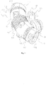
- the present invention provides a nasal pad 1.
- the nasal pad 1 comprises a nasal pad body 11 and two nasal plugs 12. During use, the user may insert the two nasal plugs 12 into his/her nostrils respectively.
- the shape of the nasal pad body 11 may be determined according to the actual requirement.
- the nasal pad body 11 may be in a circular tube shape.
- the nasal pad body 11 may be in a rectangular tube shape.
- the nasal plug 12 comprises a nasal plug body 121 fixedly connected with the nasal pad body 11.
- the fixed connection between the nasal plug body 121 and the nasal pad body 11 may be implemented by integral forming, plastic welding, or ultrasonic bonding, etc.
- two nasal plugs 12 are provided, and accordingly two nasal plug bodies 121 are provided.
- the two nasal plug bodies 121 may be inserted into the two nostrils of the user respectively.
- the shape of the nasal plug body 121 may be determined according to the actual requirement. For example, in the length direction of the nasal plug body 121, the central portion of the nasal plug body 121 has an expanded area so that the nasal plug body 121 can be fitted in the nostril of the user more tightly.
- the gas flow may flow into the nasal plug bodies 121 via the nasal pad body 11 and thereby enter into the body of the user.
- the gas flow may directly enter into the nasal plug bodies 121 through a tube line and thereby enter into the body of the user.
- the nasal pad body 11 comprises a telescoping adjustment section.
- the telescoping adjustment section refer to portion of the nasal pad body 11 with a telescoping length adjustment function.
- the length of the telescoping adjustment section may be adjusted within a certain range.
- the telescoping adjustment section may be implemented in a variety of ways.
- the telescoping adjustment section may employ corrugated tubes; or the telescoping adjustment section may employ films; or the telescoping adjustment section may employ bushing structures. All length-adjustable structures are applicable to the telescoping adjustment section in the present invention.
- the nasal pad body 11 may be composed of telescoping adjustment section entirely. Alternatively, the nasal pad body 11 may have telescoping adjustment section locally.
- the nasal plug bodies 121 may be fixedly connected with the telescoping adjustment section, or the nasal plug bodies 121 may be fixedly connected with other sections of the nasal pad body 11 other than the telescoping adjustment section.
- the telescoping adjustment section has extended length and retracted length.
- the telescoping adjustment section is configured in a way that the length of it can be adjusted between the extended length and the retracted length, thus varying the distance between the two nasal plug bodies 121.
- the extended length refers to the length of the telescoping adjustment section when the telescoping adjustment section is extended as far as possible.
- the retracted length refers to the length of the telescoping adjustment section when the telescoping adjustment section is retracted as far as possible.
- the distance between the nasal plug bodies 121 refers to the distance between the geometrical centers of the two nasal plug bodies 121 at the joints between the nasal plug bodies 121 and the nasal pad body 11.
- the distance between the two nasal plug bodies 121 may also be referred to the spacing between the two nasal plug bodies 121.
- the distance between the two nasal plug bodies 121 may be changed by adjusting the length of the telescoping adjustment section; thus, the adjustment is convenient and has low cost.
- the user may adjust the length of the telescoping adjustment section by applying force directly to the nasal pad body 11, so as to adjust the distance between the two nasal plug bodies 121.
- the length of the telescoping adjustment section may be selected according to the user's requirement, and thereby the spacing between the two nasal plug bodies 121 may be adjusted according to the user's requirement.
- the distance between the two nasal plugs 12 of the nasal pad 1 in the present invention is adjustable.
- the user may wear a respirator mask assembled with the nasal pad 1 in the present invention, and adjust the spacing between the nasal plugs 12 to an appropriate state by adjusting the length of the telescoping adjustment section.
- the user does not have to try nasal pads with nasal plugs at different spacings repeatedly; thus, the operation is simple and convenient.
- one nasal pad 1 provided in the present invention can meet different user requirements.
- the nasal pad 1 provided in the present invention effectively reduces the cost of a respiratory mask.
- the nasal pad body 11 further comprises a fixed section, which is configured in a way that the length thereof is not adjustable. Those skilled in the art should pay attention: in a case that the fixed section is made of an elastic material, the length of the fixed section may be changed slightly within the range of elastic deformation of the elastic material.
- the nasal plug bodies 121 may be fixedly connected with the fixed section.
- the fixed connections between the nasal plug bodies 121 and the fixed section may be implemented by integral forming, plastic welding, or ultrasonic bonding, etc.
- Fixedly connecting the nasal plug bodies 121 with the fixed section rather than the telescoping adjustment section is helpful for fixing the positions of the nasal plugs 12 on the nasal pad body 11 and avoiding any change of the spacing between the two nasal plug bodies 121 after the spacing is adjusted properly.
- the structure of the telescoping adjustment section is stable, and the length adjustment process of the telescoping adjustment section is smoother.
- the nasal pad body 121 comprises at least two telescoping adjustment sections and at least two fixed sections.
- the two nasal plug bodies 121 are fixedly connected with different fixed sections respectively.
- two ends of at least one of the fixed sections fixedly connected with the nasal plug bodies 121 are respectively provided with at least one of the telescoping adjustment sections. In that way, the distance from at least one nasal plug body 121 to the other nasal plug body 121 can be changed.
- the quantity of the telescoping adjustment sections and the quantity of the fixed sections may be set according to the actual requirement.
- two telescoping adjustment sections may be provided, and two fixed sections may be provided; here, the telescoping adjustment sections and the fixed sections may be arranged in an alternating form. That is to say, a telescoping adjustment section, a fixed section, another telescoping adjustment section, and another fixed section may be arranged sequentially on the nasal pad body 11, and the two fixed sections are fixedly connected with one nasal plug body 121 respectively.
- the connections between the telescoping adjustment sections and the fixed sections may be implemented by integral forming, gluing, or plastic welding, etc.
- a telescoping adjustment section is provided at each of the two ends of a fixed section that is fixedly connected with the nasal plug body 121; thus, the fixed section that is fixedly connected with the nasal plug body 121 can be moved with respect to the other fixed section, and thereby the distance between the two nasal plug bodies 121 can be changed.
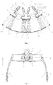
- the nasal pad body 11 comprises a first telescoping adjustment section 112, a first fixed section 113, a second telescoping adjustment section 114, a second fixed section 115, and a third telescoping adjustment section 116, which are connected sequentially.
- the two nasal plug bodies 121 are fixedly connected with the first fixed section 113 and the second fixed section 115 respectively.
- the connections between the telescoping adjustment sections and the fixed sections may be implemented by integral forming, gluing, or plastic welding, etc.
- the structure of the nasal pad body 11 may not only have the above-mentioned sections.
- a third fixed section 117 and a fourth fixed section 118 may be further provided at the free end of the first telescoping adjustment section 112 and the free end of the third telescoping adjustment section 116 respectively.
- the nasal pad body 11 comprises a third fixed section 117, a first telescoping adjustment section 112, a first fixed section 113, a second telescoping adjustment section 114, a second fixed section 115, a third telescoping adjustment section 116, and a fourth fixed section 118, which are connected sequentially.
- the extended length of the second telescoping adjustment section 114 is greater than the extended length of the first telescoping adjustment section 112 and the third telescoping adjustment section 116, and the retracted length of the second telescoping adjustment section 114 is greater than the retracted length of the first telescoping adjustment section 112 and the third telescoping adjustment section 116, so that the spacing between the two nasal plug bodies 121 can be adjusted more conveniently.
- the two nasal plug bodies 121 are fixed to the fixed sections.
- the length of the first telescoping adjustment section 112, the second telescoping adjustment section 114, and the third telescoping adjustment section 116 may be adjusted according to the requirement.
- the spacing between the two nasal plug bodies 121 will be changed as the length of the first telescoping adjustment section 112, the second telescoping adjustment section 114, and the third telescoping adjustment section 116 is adjusted.
- the nasal plug body 121 comprises a connecting portion 1222 and a nose contact portion 1223 that are connected sequentially.
- the connecting portion 1222 is fixedly connected with the nasal pad body 11, and the fixed connection between them may be implemented by integral forming, plastic welding, or ultrasonic bonding, etc.
- the cross-sectional area of the connecting portion 1222 may be the same as the cross-sectional area of the nose contact portion 1223.
- the maximum cross-sectional area of the connecting portion 1222 may be smaller than the maximum cross-sectional area of the nose contact portion 1223, and the nose contact portion 1223 is tapered gradually in a direction away from the connecting portion 1222.
- the nose contact portion 1223 may comprise two portions, i.e., an expanded portion 12231 and a contracted portion 12232 respectively.
- the expanded portion 12231 may be expanded outward in comparison with the connecting portion 1222 and the contracted portion 12232. That is to say, the expanded portion 12231 is expanded outward from the joints where the expanded portion 12231 is connected with the connecting portion 1222 and the contracted portion 12232.
- the above term “outward” refers to the direction away from the connecting portion 1222 and the contracted portion 12232.
- the expanded portion 12231 may be fitted with the inner wall of a nostril of the user, and thereby the leak tightness can be improved when the nasal plug body 121 is used.
- the contracted portion 12232 is tapered gradually in the direction away from the connecting portion 1222.
- connecting portion 1222, the expanded portion 12231, and the contracted portion 12232 may be connected together by integral forming, plastic welding, or ultrasonic bonding, etc.
- the nasal plug bodies 121 can be worn comfortably, and attain a good sealing effect against the user's nostrils.
- the nasal plug 12 further comprises at least one sealing rim 122.
- the sealing rim 122 may be made of a soft and bacteriostatic material.
- the sealing rim 122 may be made of silica gel. If a plurality of sealing rims 122 are provided, the nasal pad 1 can be fitted with the user's nostrils better, and thereby a better sealing effect can be attained.
- the sealing rim 122 is fixedly connected with the outer surface of the nasal plug body 121.
- the fixed connection between the sealing rim 122 and the nasal plug body 121 may be implemented by integral forming, plastic welding, or ultrasonic bonding, etc.
- the sealing rim 122 extends in a direction reversed from the wearing direction of the nasal plug 12.
- the direction reversed from the wearing direction of the nasal plug 12 refers to a direction reversed from the direction in which the nasal plug 12 is inserted into a nostril of the user.
- the quantity of the sealing rims 122 may be set according to the actual requirement.
- one sealing rim 122 may be provided; alternatively two sealing rims 122 may be provided, wherein, a first sealing rim 122 is fixedly connected with the end of the nasal plug body 121 away from the nasal pad body 11, and a second sealing rim 122 is closer to the nasal pad body 11 when compared with the first sealing rim 122.
- the projection of the first sealing rim 122 on the second sealing rim 122 covers the second sealing rim 122 partially.
- the telescoping adjustment sections are corrugated tubes.
- the telescoping adjustment sections in a corrugated tube structure are advantageous for reducing the cost of the nasal pad 1 and improving the convenience of length adjustment of the telescoping adjustment sections.
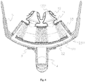
- the present invention further provides a respiratory mask.
- the respiratory mask comprises a frame 2 and the nasal pad 1 according to the present invention.
- the frame 2 comprises a frame gas inlet 21 and a nasal pad fixing portion 23.
- the nasal pad fixing portion 23 is fitted with the nasal pad body 11 to mount the nasal pad 1 on the frame 2.
- the fitting between the nasal pad fixing portion 23 and the nasal pad body 11 may be implemented in a variety of ways.
- the nasal pad fixing portion 23 may be a protrusion on the frame 2, while the nasal pad body 11 is arranged with a hole or groove, so that the nasal pad 1 can be mounted to the frame 2 by means of the fitting between the protrusion and the hole or groove; alternatively, the nasal pad fixing portion 23 and the nasal pad body 11 may be fitted with each other by snap-fitting.
- the frame gas inlet 21 is configured to lead gas flow into the nasal pad 1.
- the frame gas inlet 21 may communicate with the nasal pad body 11, which is to say, the nasal pad body 11 communicates with the frame gas inlet 21 via holes arranged in the nasal pad body 11.
- the holes arranged in the nasal pad body 11 may be in the telescoping adjustment sections or fixed sections.
- the holes via which the nasal pad body 11 communicates with the frame gas inlet 21 may be in the two ends of the nasal pad body 11.
- the holes arranged in the nasal pad body 11 are in the fixed sections; alternatively, the frame gas inlet 21 directly communicates with the nasal plug body 121 through a tube line.
- a first gas flow passage 111 is arranged in the nasal pad body 11, and a nasal pad gas inlet 1111 is arranged in the wall of the first gas flow passage 111.
- the nasal pad gas inlet 1111 may be arranged in a telescoping adjustment section or fixed section as required.
- the nasal pad gas inlet 1111 is arranged in a fixed section to avoid disturbance to the length adjustment function of the telescoping adjustment sections.
- a second gas flow passage 1221 is arranged in the nasal plug body 121. The second gas flow passage 1221 communicates with the first gas flow passage 111, so that the gas flow can flow through the nasal pad body 11 into the nasal plug body 121.
- a third gas flow passage 22 is arranged in the frame 2.
- the third gas flow passage 22 has a wall that is closed in the circumferential direction.
- the nasal pad gas inlet 1111 communicates with the third gas flow passage 22, so that the gas flow can enter into the nasal pad gas inlet 1111 via the third gas flow passage 22.
- the quantity of the nasal pad gas inlets 1111 may be set according to the actual requirement. For example, one, two or more nasal pad gas inlets 1111 may be arranged.
- the gas flow entering via the frame gas inlet 21 flows through the third gas flow passage 22, the nasal pad gas inlet 1111, the first gas flow passage 111, and the second gas flow passage 1221 sequentially, so that the gas flow is transferred into the user's body.
- the nasal pad fixing portion 23 comprises a nasal pad fixing portion body 231.
- a communicating passage 2311 is arranged in the nasal pad fixing portion body 231.
- the quantity of the nasal pad fixing portions 23 usually corresponds to the quantity of the nasal pad gas inlets 1111. For example, if there are two nasal pad gas inlets 1111, two nasal pad fixing portions 23 are arranged.
- the shape and structure of the nasal pad fixing portion body 231 may be determined according to the actual requirement.
- the nasal pad fixing portion body 231 may be in a plate shape; alternatively, the nasal pad fixing portion body 231 may be a claw structure.
- the nasal pad fixing portion body 231 is fitted with the nasal pad gas inlet 1111.
- the fitting between the nasal pad fixing portion body 231 and the nasal pad gas inlet 1111 may be implemented by inserting the nasal pad fixing portion body 231 into the nasal pad gas inlet 1111.
- the fitting between the nasal pad fixing portion body 231 and the nasal pad gas inlet 1111 may be implemented by snap fitting between the nasal pad fixing portion body 231 and the nasal pad gas inlet 1111.
- the communicating passage 2311 is configured to enable the first gas flow passage 111 to communicate with the third gas flow passage 22.
- the communicating passage 2311 enables the first gas flow passage 111 to communicate with the third gas flow passage 22, so that the gas flow can enter into the first gas flow passage 111 from the third gas flow passage 22 via the communicating passage 2311.
- the nasal pad fixing portion 23 further comprises a closing portion 232.
- the closing portion 232 is fixedly connected with the nasal pad fixing portion body 231.
- the fixed connection between the nasal pad fixing portion body 231 and the closing portion 232 may be implemented by integral forming or welding, etc.
- the shape and structure of the closing portion 232 may be determined according to the actual requirement.
- the closing portion 232 may be in a block shape.
- the closing portion 232 may be a protrusion on the surface of the claw.
- the ends of the first gas flow passage 111 have openings 1112. There is no particular restriction on the quantity of the openings 1112. Particularly, in the case that the nasal pad body 11 is in a tubular shape, both ends of the nasal pad body 11 may have an opening. That is to say, both ends of the first gas flow passage 111 have an opening 1112.
- the closing portion 232 is configured to fit with the opening 1112 to close the opening 1112.
- the fitting between the closing portion 232 and the opening 1112 may be implemented by means of fitting between the closing portions 232 and the inner wall of the first gas flow passage 111.
- the fitting between the closing portion 232 and the opening 1112 may be interference fit.
- the nasal pad body 11 is in a tubular shape, and both ends of the tubular nasal pad body 11 have an opening 1112.
- Two nasal pad gas inlets 1111 are arranged in the wall of the first gas flow passage 111 in the nasal pad body 11.
- Two nasal pad fixing portions 23 are provided, and the nasal pad fixing portion body 231 and the closing portions 232 may be formed as an integral structure.
- the two nasal pad fixing portions 23 are inserted into the two nasal pad gas inlets 1111 respectively, and the nasal pad fixing portion body 231 is fitted with grooves in the inner wall of the first gas flow passage 111, so that the nasal pad fixing portion body 231 is positioned on the nasal pad body 11.
- the communicating passage 2311 enables the third gas flow passage 22 to communicate with the first gas flow passage 111.
- the closing portions 232 are fitted with the inner wall of the nasal pad body 11 to close the openings 1112 at the two ends of the tubular nasal pad body 11. The ends of the closing portions 232 are flush with the ends of the openings 1112 of the nasal pad body 11 respectively.
- the respiratory mask further comprises a length adjusting member 3.
- the length adjusting member 3 comprises a connecting portion 31 and a sliding portion 32.
- the nasal pad body 11 comprises a fitting portion 119, the connecting portion 31 is connected with the fitting portion 119, so that the length adjusting member 3 and the nasal pad body 11 are connected together.
- the fitting portion 119 may be a boss arranged on the outer surface of the nasal pad body 11.
- the fitting portion 119 may be connected with the nasal pad body 11 by welding, gluing, or integral forming, etc.
- connection between the connecting portion 31 and the fitting portion 119 may be implemented in a variety of ways.
- the connecting portion 31 may be connected with the fitting portion 119 by snap fitting; alternatively, the connecting portion 31 may be connected with the fitting portion 119 by gluing; alternatively, the connecting portion 31 may be connected with the fitting portion 119 by bolting.
- the sliding portion 32 is slidably fitted with the frame 2.
- the length adjusting member 3 drives the fitting portion 119 to slide along the frame 2, so that the length of the telescoping adjustment sections can be adjusted between the extended length and the retracted length.
- the fitting portion 119 connected with the connecting portion 31 of the length adjusting member 3 moves together with the length adjusting member 3 so that the length of the telescoping adjustment sections is changed and thereby the distance between the two nasal plug bodies 121 is changed.
- a slide groove 24 may be arranged on the frame 2, and the sliding portion 32 may comprise a slide block 321 slidably fitted with the slide groove 24.
- the length adjusting member 3 can slide with respect to the frame 2, and the purpose of adjusting the length of the telescoping adjustment sections can be attained.
- the slide groove 24 may be a slide groove with openings at the ends, so that the sliding portion 32 of the length adjusting member 3 can be assembled into the slide groove 24 more conveniently.
- the length adjusting member 3 preferably is an integrally formed structure. Alternatively, the connecting portion 31 and the sliding portion 32 may be fixed together by plastic welding or gluing. Preferably, a plurality of first positioning structures 25 are provided on the frame 2. A second positioning structure (not shown in the figures) is provided on the length adjusting member 3.
- the second positioning structure is fitted with one of the plurality of first positioning structures 25 to fix the length adjusting member 3 at a position on the frame 2.
- the second positioning structure may be a protrusion or groove
- the first positioning structure 25 may be a groove or protrusion fitted with the second positioning structure.
- the position of the length adjusting member 3 on the frame 2 can be fixed.
- the length adjusting member 3 can be adjusted so that the second positioning structure is fitted with a different first positioning structure 25.
- the arrangement of the second positioning structure and the first positioning structures 25 is advantageous for keeping the length adjusting member 3 at a position on the frame 2 to prevent the distance between the two nasal plugs 12 from changed uncontrollably after the distance is adjusted to an appropriate value.
- numbers, letters, or symbols corresponding to the first positioning structures 25 may be arranged on the frame 2, and a window for viewing the numbers, letters, or symbols may be arranged on the length adjusting member 3.
- the length adjusting member 3 slides to such an extent that the second positioning structure is fitted with a first positioning structure 25, the user may view a corresponding number, letter, or symbol through the window on the length adjusting member 3, and thereby the position of the length adjusting member 3 on the frame 2 can be ascertained. In that way, the user can clearly know the position of the length adjusting member 3 on the frame 2.
- the respiratory mask further comprises a connection pipe 4 and a head band connecting arm 5.
- connection pipe 4 is connected with the frame gas inlet 21 to convey the gas into the frame gas inlet 21.
- the connection between the connection pipe 4 and the frame gas inlet 21 may be implemented by means of snap-fit connection, magnetic connection, mechanical interlocking, or frictional connection, etc.
- the connection between the connection pipe 4 and the frame gas inlet 21 is a ball-socket connection, so that the connection pipe 4 can rotate with respect to the frame 2. In use, the user may install or remove the connection pipe 4 as required.
- the head band connecting arm 5 is connected with the frame 2, and a head band may be fixed to the head band connecting arm 5.
- the connection between the head band connecting arm 5 and the frame 2 may be implemented in a variety of ways.
- the head band connecting arm 5 may be welded to the frame 2; alternatively, the head band connecting arm 5 may be connected to the frame 2 by snap fitting.
- the head band connecting arm 5 is provided with a head band connecting portion 51
- the third gas flow passage 22 of the frame 2 has an opening
- the head band connecting arm 5 and the frame 2 are connected by means of the fitting between the head band connecting portion 51 and the opening.
- the head band connecting portion 51 of the head band connecting arm 5 closes the opening of the third gas flow passage 22.
- the nasal pad body 11 is in a tubular shape, a first gas flow passage 111 is arranged in the nasal pad body 11, and the two ends of the tubular nasal pad body 11 have an opening respectively.
- the nasal pad body 11 comprises a third fixed section 117, a first telescoping adjustment section 112, a first fixed section 113, a second telescoping adjustment section 114, a second fixed section 115, a third telescoping adjustment section 116, and a fourth fixed section 118, which are arranged sequentially.
- the first fixed section 113 and the second fixed section 115 are provided with a fitting portion 119 respectively.
- the third fixed section 117 and the fourth fixed section 118 are provided with a nasal pad gas inlet 1111 respectively.
- a second gas flow passage 1221 is arranged in the nasal plug 12.
- the nasal plug 12 comprises a nasal plug body 121 and a sealing rim 122.
- the nasal plug body 121 comprises a connecting portion 1222, an expanded portion 12231, and a contracted portion 12232, which are connected sequentially.
- the two nasal plug bodies 121 are fixedly connected with the first fixed section 113 and the second fixed section 115 respectively.
- Each nasal plug body 121 has two sealing rims 122.
- a third gas flow passage 22 is arranged in the frame 2.
- the frame 2 comprises a frame gas inlet 21, nasal pad fixing portions 23, a slide groove 24, and first positioning structures 25.
- two nasal pad fixing portions 23 are arranged.
- the nasal pad fixing portion 23 comprises a nasal pad fixing portion body 231 and a closing portion 232.
- a communicating passage 2311 is arranged in the nasal pad fixing portion body 231.
- the two nasal pad fixing portions 23 are inserted into the two nasal pad gas inlets 1111 respectively.
- the communicating passage 2311 enables the third gas flow passage 22 to communicate with the first gas flow passage 111.
- the two closing portions 232 are fitted with the first gas flow passage 111 respectively so as to close the openings 1112 at the two ends of the tubular nasal pad body 11.
- the length adjusting member 3 comprises connecting portions 31, sliding portions 32, and a second positioning structure. Two length adjusting members 3 are arranged. The two connecting portions 31 are connected with the two fitting portions 119 respectively, and the slide blocks 321 of the two sliding portions 32 are slidably fitted with the slide groove 24. The length adjusting member 3 can slide along the slide groove 24 with respect to the frame 2, and the second positioning structure can be fitted with a first positioning structure 25.
- connection pipe 4 is rotatably connected with the frame gas inlet 21.
- the head band connecting portions 51 of the two head band connecting arms 5 are fitted with the openings at the two ends of the third gas flow passage 22 respectively to close the openings at the two ends of the third gas flow passage 22.
- the user applies certain force to the length adjusting member 3, so that the length adjusting member 3 slides along the slide groove 24 of the frame 2.
- the length of the first telescoping adjustment section 112, the second telescoping adjustment section 114, and the third telescoping adjustment section 116 is changed.
- the distance between the two nasal plug bodies 121 on the first fixed section 113 and the second fixed section 115 is changed, and thereby the purpose of adjusting the spacing between the nasal plugs is attained.
- the length adjusting member 3 can be adjusted so that the second positioning structure is fitted with a different first positioning structure 25.
- the user may view the numbers on the frame 2 through the window on the length adjusting member 3, and thereby ascertain the position of the length adjusting member 3 on the frame 2 at this point.
- the gas flow entering into the frame gas inlet 21 through the connection pipe 4 flows through the third gas flow passage 22, the communicating passage 2311, the first gas flow passage 111, and the second gas flow passage 1221 sequentially, and then enters into the user's body.
Landscapes
- Health & Medical Sciences (AREA)
- Pulmonology (AREA)
- Emergency Medicine (AREA)
- Heart & Thoracic Surgery (AREA)
- Anesthesiology (AREA)
- Biomedical Technology (AREA)
- Engineering & Computer Science (AREA)
- Hematology (AREA)
- Life Sciences & Earth Sciences (AREA)
- Animal Behavior & Ethology (AREA)
- General Health & Medical Sciences (AREA)
- Public Health (AREA)
- Veterinary Medicine (AREA)
- Otolaryngology (AREA)
- Respiratory Apparatuses And Protective Means (AREA)
Claims (10)
- Masque respiratoire, comprenant
un cadre (2) et un tampon nasal (1) pour masque respiratoire,
le cadre (2) comprenant une portion de fixation de tampon nasal (23) ;
le tampon nasal (1) comprenant un corps de tampon nasal (11) et deux bouchons nasaux (12),
la portion de fixation de tampon nasal (23) étant ajustée au corps de tampon nasal (11) afin de monter le tampon nasal sur le cadre (2) ;
chacun des bouchons nasaux comprenant un corps de bouchon nasal relié de manière fixe au corps de tampon nasal ;
le corps de tampon nasal (11) comprenant au moins deux sections d'ajustement télescopique (112, 114) ;
les sections d'ajustement télescopique (114) ayant une longueur étendue et une longueur rétractée et étant conçues de manière à ce que leurs longueurs puissent être ajustées entre la longueur étendue et la longueur rétractée, faisant ainsi varier la distance entre les deux corps de bouchon nasaux (121) ;
caractérisé en ce que,
le cadre (2) comprend en outre un orifice d'entrée de gaz de cadre (21) conçu pour conduire l'écoulement de gaz dans le tampon nasal (1) ;
le corps de tampon nasal (11) comprenant au moins deux sections fixes (113, 115) ;
les sections fixes (113, 115) étant conçues de manière telle que leurs longueurs ne soient pas ajustables ;
les deux corps de bouchon nasaux (121) étant reliés de manière fixe à différentes sections fixes (113, 115) ;
deux extrémités d'au moins l'une des sections fixes (113) reliées de manière fixe aux corps de bouchon nasaux (121) étant respectivement pourvues d'au moins l'une des sections d'ajustement télescopique (112, 114). - Masque respiratoire selon la revendication 1, le corps de bouchon nasal (121) comprenant une portion de connexion (1222) et une portion de contact avec le nez (1223) qui sont reliées de manière séquentielle, et la portion de connexion (1222) étant reliée de manière fixe au corps de tampon nasal (11), la surface de section transversale de la portion de connexion (1222) étant la même que la surface de section transversale de la portion de contact avec le nez (1223) ; ou
la surface de section transversale maximale de la portion de connexion (1222) étant inférieure à la surface de section transversale maximale de la portion de contact avec le nez (1223), et la portion de contact avec le nez (1223) étant effilée progressivement dans un sens à l'opposé de la portion de connexion (1222). - Masque respiratoire selon la revendication 1, le bouchon nasal (12) comprenant en outre au moins un bord d'étanchéité (122),
le bord d'étanchéité (122) étant relié de manière fixe à la surface externe du corps de bouchon nasal (121) ;
le bord d'étanchéité (122) s'étendant dans un sens opposé au sens de port des bouchons nasaux (12). - Masque respiratoire tel que selon l'une quelconque des revendications 1 à 3, la section d'ajustement télescopique (112, 114, 116) utilisant des tubes ondulés.
- Masque respiratoire selon la revendication 4, un premier passage d'écoulement de gaz (111) étant disposé dans le corps de tampon nasal (11), et un orifice d'entrée de gaz de tampon nasal (111) étant disposé dans la paroi latérale du corps de tampon nasal (11) ;
un second passage d'écoulement de gaz étant disposé dans le corps de bouchon nasal (121) ;
un troisième passage d'écoulement de gaz étant disposé dans le cadre (2) ;
l'orifice d'entrée de gaz de tampon nasal (111) communiquant avec le troisième passage d'écoulement de gaz ;
l'écoulement de gaz pénétrant via l'orifice d'entrée de gaz de cadre (21) s'écoulant à travers le troisième passage d'écoulement de gaz, l'orifice d'entrée de gaz de tampon nasal (111), le premier passage d'écoulement de gaz (111), et le second passage d'écoulement de gaz de manière séquentielle. - Masque respiratoire selon la revendication 5, la portion de fixation de tampon nasal (23) comprenant un corps de portion de fixation de tampon nasal (231), et un passage de communication (2311) étant disposé dans le corps de portion de fixation de tampon nasal (231) ;
le passage de communication (2311) étant conçu pour faire communiquer le premier passage d'écoulement de gaz (111) avec le troisième passage d'écoulement de gaz. - Masque respiratoire selon la revendication 6, la portion de fixation de tampon nasal (23) comprenant en outre une portion de fermeture (232) reliée de manière fixe au corps de portion de fixation de tampon nasal (231) ;
l'extrémité du premier passage d'écoulement de gaz (111) ayant une ouverture (1112) ;
la portion de fermeture (232) étant conçue pour s'ajuster à l'ouverture (1112) afin de fermer l'ouverture (1112). - Masque respiratoire selon la revendication 4,
le masque respiratoire comprenant en outre un élément d'ajustement de longueur (3) ;
le tampon nasal comprenant une portion d'ajustement (119) disposée sur le corps de tampon nasal (11) ;
l'élément d'ajustement de longueur (3) comprenant une portion de connexion (1222) et une portion coulissante (32),
la portion de connexion (1222) étant reliée à la portion d'ajustement (119) ;
la portion coulissante (32) étant ajustée de manière à pouvoir coulisser au cadre (2) ;
l'élément d'ajustement de longueur (3) pouvant amener la portion d'ajustement (119) à coulisser le long du cadre (2), de sorte que la longueur de la section d'ajustement télescopique (112, 114, 116) est ajustée entre la longueur étendue et la longueur rétractée. - Masque respiratoire selon la revendication 8, une rainure de coulissement (24) étant ménagée sur le cadre (2), et la portion coulissante (32) comprenant un bloc coulissant (321) ajusté de manière à pouvoir coulisser au niveau de la rainure de coulissement (24).
- Masque respiratoire selon la revendication 9,
une pluralité de premières structures de positionnement (25) étant ménagées sur le cadre (2) ;
une seconde structure de positionnement étant ménagée sur l'élément d'ajustement de longueur (3) ;
la seconde structure de positionnement étant ajustée sur l'une de la pluralité des premières structures de positionnement (25) pour fixer l'élément d'ajustement de longueur (3) à une position sur le cadre (2).
Applications Claiming Priority (2)
| Application Number | Priority Date | Filing Date | Title |
|---|---|---|---|
| CN201710010122.2A CN106693140B (zh) | 2017-01-06 | 2017-01-06 | 一种呼吸面罩鼻垫和呼吸面罩 |
| PCT/CN2017/116048 WO2018126864A1 (fr) | 2017-01-06 | 2017-12-14 | Coussinet de nez de masque respiratoire et masque respiratoire |
Publications (3)
| Publication Number | Publication Date |
|---|---|
| EP3566735A1 EP3566735A1 (fr) | 2019-11-13 |
| EP3566735A4 EP3566735A4 (fr) | 2020-01-01 |
| EP3566735B1 true EP3566735B1 (fr) | 2021-05-19 |
Family
ID=58908371
Family Applications (1)
| Application Number | Title | Priority Date | Filing Date |
|---|---|---|---|
| EP17890306.8A Active EP3566735B1 (fr) | 2017-01-06 | 2017-12-14 | Coussinet de nez de masque respiratoire et masque respiratoire |
Country Status (4)
| Country | Link |
|---|---|
| US (1) | US11357945B2 (fr) |
| EP (1) | EP3566735B1 (fr) |
| CN (1) | CN106693140B (fr) |
| WO (1) | WO2018126864A1 (fr) |
Families Citing this family (13)
| Publication number | Priority date | Publication date | Assignee | Title |
|---|---|---|---|---|
| CN106693140B (zh) * | 2017-01-06 | 2020-02-07 | 北京怡和嘉业医疗科技股份有限公司 | 一种呼吸面罩鼻垫和呼吸面罩 |
| CN113226420B (zh) * | 2019-01-22 | 2024-02-20 | 深圳迈瑞生物医疗电子股份有限公司 | 呼吸鼻塞、鼻塞配件及呼吸系统 |
| CN110898405B (zh) * | 2019-12-23 | 2025-01-28 | 程文君 | 一种内夹式鼻夹 |
| CN111228667A (zh) * | 2020-03-12 | 2020-06-05 | 优仕康生(天津)科技发展有限公司 | 类π字形仿生四通呼吸卫生防护器 |
| CN111840735B (zh) * | 2020-06-29 | 2023-04-18 | 青岛大学附属医院 | 一种麻醉用鼻罩 |
| WO2022147488A1 (fr) * | 2021-01-04 | 2022-07-07 | Ghadimi Kamrouz | Nouveaux masques faciaux et procédés correspondants |
| CN112870517A (zh) * | 2021-01-21 | 2021-06-01 | 湖南泰贵生物科技有限公司 | 一种无创呼吸机的智能鼻罩固定装置 |
| TW202306840A (zh) * | 2021-08-13 | 2023-02-16 | 誠加興業股份有限公司 | 用於一呼吸管之口鼻擋水結構 |
| CN114887172B (zh) * | 2022-05-20 | 2025-02-21 | 王宇 | 新生儿临床用呼吸机 |
| EP4603125A1 (fr) * | 2022-10-14 | 2025-08-20 | Magos Co., Ltd. | Outil d'assistance respiratoire, dispositif d'assistance respiratoire et élément d'élimination d'humidité |
| JP7317414B1 (ja) | 2022-10-14 | 2023-07-31 | 株式会社Magos | 呼吸補助具、呼吸補助装置 |
| CN120789418B (zh) * | 2025-09-15 | 2026-04-24 | 沈阳迈思医疗科技有限公司 | 一种鼻塞导管结构 |
| CN121314023A (zh) * | 2025-10-13 | 2026-01-13 | 应急总医院 | 鼻呼吸装置 |
Family Cites Families (20)
| Publication number | Priority date | Publication date | Assignee | Title |
|---|---|---|---|---|
| US4782832A (en) * | 1987-07-30 | 1988-11-08 | Puritan-Bennett Corporation | Nasal puff with adjustable sealing means |
| US6763832B1 (en) * | 1999-04-27 | 2004-07-20 | Loma Linda University Medical Center | Device and method for the administration of oxygen |
| US6431172B1 (en) * | 2000-10-20 | 2002-08-13 | Mallinckrodt Inc. | Nasal cannula with inflatable plenum chamber |
| US8783257B2 (en) | 2004-02-23 | 2014-07-22 | Fisher & Paykel Healthcare Limited | Breathing assistance apparatus |
| WO2005097247A1 (fr) * | 2004-04-09 | 2005-10-20 | Resmed Limited | Ensemble nasal |
| US7481219B2 (en) * | 2004-06-18 | 2009-01-27 | Mergenet Medical, Inc. | Medicine delivery interface system |
| US20060107958A1 (en) * | 2004-11-22 | 2006-05-25 | Sleeper Geoffrey P | Adjustable sealing nasal cannula |
| DE102008010475A1 (de) | 2008-02-21 | 2009-08-27 | Seleon Gmbh | Applikatoren für eine Luftbrille |
| WO2009151344A1 (fr) * | 2008-06-12 | 2009-12-17 | Fisher & Paykel Healthcare Limited | Interface nasale respiratoire dotée de coiffes d'étanchéité |
| US20110240035A1 (en) * | 2008-11-21 | 2011-10-06 | Bidibots Pty Ltd | Respiratory assistance device and system and method |
| ES2736776T3 (es) * | 2010-10-18 | 2020-01-07 | Fisher & Paykel Healthcare Ltd | Cánula nasal, conducto y sistema de sujeción |
| CN103143097B (zh) * | 2011-12-07 | 2015-08-12 | 雃博股份有限公司 | 呼吸治疗面罩 |
| CN105142705B (zh) * | 2013-04-23 | 2019-04-16 | 皇家飞利浦有限公司 | 患者接口设备 |
| WO2014207594A1 (fr) | 2013-06-13 | 2014-12-31 | Koninklijke Philips N.V. | Dispositifs d'interface avec un patient avec attachement adhésif |
| CN203749967U (zh) * | 2014-03-18 | 2014-08-06 | 山东省文登整骨医院 | 新型吸氧管 |
| EP3169391B1 (fr) * | 2014-07-16 | 2019-06-26 | Human Design Medical, LLC | Système de harnais et interface faciale à utiliser avec des systèmes de ventilation et à pression expiratoire positive |
| CN204637203U (zh) * | 2015-03-23 | 2015-09-16 | 中国人民解放军总医院 | 一种医用吸氧管 |
| EP4364770A3 (fr) * | 2015-03-31 | 2024-07-17 | Fisher & Paykel Healthcare Limited | Canule nasale |
| CN204910378U (zh) * | 2015-07-06 | 2015-12-30 | 中国人民解放军第四军医大学 | 一种可调节氧气管 |
| CN106693140B (zh) * | 2017-01-06 | 2020-02-07 | 北京怡和嘉业医疗科技股份有限公司 | 一种呼吸面罩鼻垫和呼吸面罩 |
-
2017
- 2017-01-06 CN CN201710010122.2A patent/CN106693140B/zh active Active
- 2017-12-14 US US16/476,232 patent/US11357945B2/en active Active
- 2017-12-14 WO PCT/CN2017/116048 patent/WO2018126864A1/fr not_active Ceased
- 2017-12-14 EP EP17890306.8A patent/EP3566735B1/fr active Active
Also Published As
| Publication number | Publication date |
|---|---|
| CN106693140B (zh) | 2020-02-07 |
| EP3566735A1 (fr) | 2019-11-13 |
| EP3566735A4 (fr) | 2020-01-01 |
| WO2018126864A1 (fr) | 2018-07-12 |
| US11357945B2 (en) | 2022-06-14 |
| US20190351170A1 (en) | 2019-11-21 |
| CN106693140A (zh) | 2017-05-24 |
Similar Documents
| Publication | Publication Date | Title |
|---|---|---|
| EP3566735B1 (fr) | Coussinet de nez de masque respiratoire et masque respiratoire | |
| US20220160982A1 (en) | Cushion for mask system | |
| US20250161613A1 (en) | Patient interfaces | |
| CN101683545B (zh) | 通气口组件和具有该通气口组件的鼻面罩 | |
| JP6270478B2 (ja) | 自動調節クッションを備える患者インターフェース装置 | |
| AU2017293759B2 (en) | A vent for a component of a respiratory therapy system | |
| EP2747819B1 (fr) | Interface patient ayant un raccord encliquetable | |
| EP3033131B1 (fr) | Élément de raccordement fluidique comprenant un élément valve | |
| JP6023711B2 (ja) | 二重y支持構造を有するフレーム組立体を備える患者インターフェース装置 | |
| EP3300759B1 (fr) | Ensemble masque | |
| US20130263858A1 (en) | Support element for use with patient interface device | |
| JP7203463B2 (ja) | 呼吸マスク、及び換気療法デバイス | |
| CN103906546A (zh) | 具有用于夹子或带的头架立柱的患者界面 | |
| JP2016501089A (ja) | 呼吸インターフェースデバイス用のモーションスタビライザシステム | |
| EP2994183A1 (fr) | Masque stabilise | |
| CN112638458B (zh) | 鼻部分和包括该鼻部分的患者界面装置 | |
| CN115154814A (zh) | 呼吸面罩及通气设备 |
Legal Events
| Date | Code | Title | Description |
|---|---|---|---|
| STAA | Information on the status of an ep patent application or granted ep patent |
Free format text: STATUS: THE INTERNATIONAL PUBLICATION HAS BEEN MADE |
|
| PUAI | Public reference made under article 153(3) epc to a published international application that has entered the european phase |
Free format text: ORIGINAL CODE: 0009012 |
|
| STAA | Information on the status of an ep patent application or granted ep patent |
Free format text: STATUS: REQUEST FOR EXAMINATION WAS MADE |
|
| 17P | Request for examination filed |
Effective date: 20190806 |
|
| AK | Designated contracting states |
Kind code of ref document: A1 Designated state(s): AL AT BE BG CH CY CZ DE DK EE ES FI FR GB GR HR HU IE IS IT LI LT LU LV MC MK MT NL NO PL PT RO RS SE SI SK SM TR |
|
| AX | Request for extension of the european patent |
Extension state: BA ME |
|
| A4 | Supplementary search report drawn up and despatched |
Effective date: 20191202 |
|
| RIC1 | Information provided on ipc code assigned before grant |
Ipc: A61M 16/06 20060101AFI20191126BHEP |
|
| DAV | Request for validation of the european patent (deleted) | ||
| DAX | Request for extension of the european patent (deleted) | ||
| GRAP | Despatch of communication of intention to grant a patent |
Free format text: ORIGINAL CODE: EPIDOSNIGR1 |
|
| STAA | Information on the status of an ep patent application or granted ep patent |
Free format text: STATUS: GRANT OF PATENT IS INTENDED |
|
| INTG | Intention to grant announced |
Effective date: 20201222 |
|
| GRAS | Grant fee paid |
Free format text: ORIGINAL CODE: EPIDOSNIGR3 |
|
| GRAA | (expected) grant |
Free format text: ORIGINAL CODE: 0009210 |
|
| STAA | Information on the status of an ep patent application or granted ep patent |
Free format text: STATUS: THE PATENT HAS BEEN GRANTED |
|
| REG | Reference to a national code |
Ref country code: DE Ref legal event code: R082 Ref document number: 602017039043 Country of ref document: DE Representative=s name: GRUENECKER PATENT- UND RECHTSANWAELTE PARTG MB, DE |
|
| AK | Designated contracting states |
Kind code of ref document: B1 Designated state(s): AL AT BE BG CH CY CZ DE DK EE ES FI FR GB GR HR HU IE IS IT LI LT LU LV MC MK MT NL NO PL PT RO RS SE SI SK SM TR |
|
| REG | Reference to a national code |
Ref country code: GB Ref legal event code: FG4D |
|
| REG | Reference to a national code |
Ref country code: CH Ref legal event code: EP |
|
| REG | Reference to a national code |
Ref country code: DE Ref legal event code: R096 Ref document number: 602017039043 Country of ref document: DE |
|
| REG | Reference to a national code |
Ref country code: AT Ref legal event code: REF Ref document number: 1393391 Country of ref document: AT Kind code of ref document: T Effective date: 20210615 |
|
| REG | Reference to a national code |
Ref country code: IE Ref legal event code: FG4D |
|
| REG | Reference to a national code |
Ref country code: LT Ref legal event code: MG9D |
|
| REG | Reference to a national code |
Ref country code: AT Ref legal event code: MK05 Ref document number: 1393391 Country of ref document: AT Kind code of ref document: T Effective date: 20210519 |
|
| REG | Reference to a national code |
Ref country code: NL Ref legal event code: MP Effective date: 20210519 |
|
| PG25 | Lapsed in a contracting state [announced via postgrant information from national office to epo] |
Ref country code: LT Free format text: LAPSE BECAUSE OF FAILURE TO SUBMIT A TRANSLATION OF THE DESCRIPTION OR TO PAY THE FEE WITHIN THE PRESCRIBED TIME-LIMIT Effective date: 20210519 Ref country code: FI Free format text: LAPSE BECAUSE OF FAILURE TO SUBMIT A TRANSLATION OF THE DESCRIPTION OR TO PAY THE FEE WITHIN THE PRESCRIBED TIME-LIMIT Effective date: 20210519 Ref country code: HR Free format text: LAPSE BECAUSE OF FAILURE TO SUBMIT A TRANSLATION OF THE DESCRIPTION OR TO PAY THE FEE WITHIN THE PRESCRIBED TIME-LIMIT Effective date: 20210519 Ref country code: AT Free format text: LAPSE BECAUSE OF FAILURE TO SUBMIT A TRANSLATION OF THE DESCRIPTION OR TO PAY THE FEE WITHIN THE PRESCRIBED TIME-LIMIT Effective date: 20210519 Ref country code: BG Free format text: LAPSE BECAUSE OF FAILURE TO SUBMIT A TRANSLATION OF THE DESCRIPTION OR TO PAY THE FEE WITHIN THE PRESCRIBED TIME-LIMIT Effective date: 20210819 |
|
| PG25 | Lapsed in a contracting state [announced via postgrant information from national office to epo] |
Ref country code: IS Free format text: LAPSE BECAUSE OF FAILURE TO SUBMIT A TRANSLATION OF THE DESCRIPTION OR TO PAY THE FEE WITHIN THE PRESCRIBED TIME-LIMIT Effective date: 20210919 Ref country code: GR Free format text: LAPSE BECAUSE OF FAILURE TO SUBMIT A TRANSLATION OF THE DESCRIPTION OR TO PAY THE FEE WITHIN THE PRESCRIBED TIME-LIMIT Effective date: 20210820 Ref country code: NO Free format text: LAPSE BECAUSE OF FAILURE TO SUBMIT A TRANSLATION OF THE DESCRIPTION OR TO PAY THE FEE WITHIN THE PRESCRIBED TIME-LIMIT Effective date: 20210819 Ref country code: LV Free format text: LAPSE BECAUSE OF FAILURE TO SUBMIT A TRANSLATION OF THE DESCRIPTION OR TO PAY THE FEE WITHIN THE PRESCRIBED TIME-LIMIT Effective date: 20210519 Ref country code: PL Free format text: LAPSE BECAUSE OF FAILURE TO SUBMIT A TRANSLATION OF THE DESCRIPTION OR TO PAY THE FEE WITHIN THE PRESCRIBED TIME-LIMIT Effective date: 20210519 Ref country code: PT Free format text: LAPSE BECAUSE OF FAILURE TO SUBMIT A TRANSLATION OF THE DESCRIPTION OR TO PAY THE FEE WITHIN THE PRESCRIBED TIME-LIMIT Effective date: 20210920 Ref country code: SE Free format text: LAPSE BECAUSE OF FAILURE TO SUBMIT A TRANSLATION OF THE DESCRIPTION OR TO PAY THE FEE WITHIN THE PRESCRIBED TIME-LIMIT Effective date: 20210519 Ref country code: RS Free format text: LAPSE BECAUSE OF FAILURE TO SUBMIT A TRANSLATION OF THE DESCRIPTION OR TO PAY THE FEE WITHIN THE PRESCRIBED TIME-LIMIT Effective date: 20210519 |
|
| PG25 | Lapsed in a contracting state [announced via postgrant information from national office to epo] |
Ref country code: NL Free format text: LAPSE BECAUSE OF FAILURE TO SUBMIT A TRANSLATION OF THE DESCRIPTION OR TO PAY THE FEE WITHIN THE PRESCRIBED TIME-LIMIT Effective date: 20210519 |
|
| PG25 | Lapsed in a contracting state [announced via postgrant information from national office to epo] |
Ref country code: SK Free format text: LAPSE BECAUSE OF FAILURE TO SUBMIT A TRANSLATION OF THE DESCRIPTION OR TO PAY THE FEE WITHIN THE PRESCRIBED TIME-LIMIT Effective date: 20210519 Ref country code: SM Free format text: LAPSE BECAUSE OF FAILURE TO SUBMIT A TRANSLATION OF THE DESCRIPTION OR TO PAY THE FEE WITHIN THE PRESCRIBED TIME-LIMIT Effective date: 20210519 Ref country code: EE Free format text: LAPSE BECAUSE OF FAILURE TO SUBMIT A TRANSLATION OF THE DESCRIPTION OR TO PAY THE FEE WITHIN THE PRESCRIBED TIME-LIMIT Effective date: 20210519 Ref country code: ES Free format text: LAPSE BECAUSE OF FAILURE TO SUBMIT A TRANSLATION OF THE DESCRIPTION OR TO PAY THE FEE WITHIN THE PRESCRIBED TIME-LIMIT Effective date: 20210519 Ref country code: CZ Free format text: LAPSE BECAUSE OF FAILURE TO SUBMIT A TRANSLATION OF THE DESCRIPTION OR TO PAY THE FEE WITHIN THE PRESCRIBED TIME-LIMIT Effective date: 20210519 Ref country code: DK Free format text: LAPSE BECAUSE OF FAILURE TO SUBMIT A TRANSLATION OF THE DESCRIPTION OR TO PAY THE FEE WITHIN THE PRESCRIBED TIME-LIMIT Effective date: 20210519 Ref country code: RO Free format text: LAPSE BECAUSE OF FAILURE TO SUBMIT A TRANSLATION OF THE DESCRIPTION OR TO PAY THE FEE WITHIN THE PRESCRIBED TIME-LIMIT Effective date: 20210519 |
|
| REG | Reference to a national code |
Ref country code: DE Ref legal event code: R097 Ref document number: 602017039043 Country of ref document: DE |
|
| PLBE | No opposition filed within time limit |
Free format text: ORIGINAL CODE: 0009261 |
|
| STAA | Information on the status of an ep patent application or granted ep patent |
Free format text: STATUS: NO OPPOSITION FILED WITHIN TIME LIMIT |
|
| 26N | No opposition filed |
Effective date: 20220222 |
|
| PG25 | Lapsed in a contracting state [announced via postgrant information from national office to epo] |
Ref country code: IS Free format text: LAPSE BECAUSE OF FAILURE TO SUBMIT A TRANSLATION OF THE DESCRIPTION OR TO PAY THE FEE WITHIN THE PRESCRIBED TIME-LIMIT Effective date: 20210919 Ref country code: AL Free format text: LAPSE BECAUSE OF FAILURE TO SUBMIT A TRANSLATION OF THE DESCRIPTION OR TO PAY THE FEE WITHIN THE PRESCRIBED TIME-LIMIT Effective date: 20210519 |
|
| PG25 | Lapsed in a contracting state [announced via postgrant information from national office to epo] |
Ref country code: MC Free format text: LAPSE BECAUSE OF FAILURE TO SUBMIT A TRANSLATION OF THE DESCRIPTION OR TO PAY THE FEE WITHIN THE PRESCRIBED TIME-LIMIT Effective date: 20210519 Ref country code: IT Free format text: LAPSE BECAUSE OF FAILURE TO SUBMIT A TRANSLATION OF THE DESCRIPTION OR TO PAY THE FEE WITHIN THE PRESCRIBED TIME-LIMIT Effective date: 20210519 |
|
| REG | Reference to a national code |
Ref country code: CH Ref legal event code: PL |
|
| REG | Reference to a national code |
Ref country code: BE Ref legal event code: MM Effective date: 20211231 |
|
| PG25 | Lapsed in a contracting state [announced via postgrant information from national office to epo] |
Ref country code: LU Free format text: LAPSE BECAUSE OF NON-PAYMENT OF DUE FEES Effective date: 20211214 Ref country code: IE Free format text: LAPSE BECAUSE OF NON-PAYMENT OF DUE FEES Effective date: 20211214 |
|
| PG25 | Lapsed in a contracting state [announced via postgrant information from national office to epo] |
Ref country code: BE Free format text: LAPSE BECAUSE OF NON-PAYMENT OF DUE FEES Effective date: 20211231 |
|
| PG25 | Lapsed in a contracting state [announced via postgrant information from national office to epo] |
Ref country code: LI Free format text: LAPSE BECAUSE OF NON-PAYMENT OF DUE FEES Effective date: 20211231 Ref country code: CH Free format text: LAPSE BECAUSE OF NON-PAYMENT OF DUE FEES Effective date: 20211231 |
|
| PG25 | Lapsed in a contracting state [announced via postgrant information from national office to epo] |
Ref country code: CY Free format text: LAPSE BECAUSE OF FAILURE TO SUBMIT A TRANSLATION OF THE DESCRIPTION OR TO PAY THE FEE WITHIN THE PRESCRIBED TIME-LIMIT Effective date: 20210519 |
|
| PG25 | Lapsed in a contracting state [announced via postgrant information from national office to epo] |
Ref country code: HU Free format text: LAPSE BECAUSE OF FAILURE TO SUBMIT A TRANSLATION OF THE DESCRIPTION OR TO PAY THE FEE WITHIN THE PRESCRIBED TIME-LIMIT; INVALID AB INITIO Effective date: 20171214 |
|
| PG25 | Lapsed in a contracting state [announced via postgrant information from national office to epo] |
Ref country code: MK Free format text: LAPSE BECAUSE OF FAILURE TO SUBMIT A TRANSLATION OF THE DESCRIPTION OR TO PAY THE FEE WITHIN THE PRESCRIBED TIME-LIMIT Effective date: 20210519 |
|
| PG25 | Lapsed in a contracting state [announced via postgrant information from national office to epo] |
Ref country code: TR Free format text: LAPSE BECAUSE OF FAILURE TO SUBMIT A TRANSLATION OF THE DESCRIPTION OR TO PAY THE FEE WITHIN THE PRESCRIBED TIME-LIMIT Effective date: 20210519 |
|
| PG25 | Lapsed in a contracting state [announced via postgrant information from national office to epo] |
Ref country code: MT Free format text: LAPSE BECAUSE OF FAILURE TO SUBMIT A TRANSLATION OF THE DESCRIPTION OR TO PAY THE FEE WITHIN THE PRESCRIBED TIME-LIMIT Effective date: 20210519 |
|
| PGFP | Annual fee paid to national office [announced via postgrant information from national office to epo] |
Ref country code: GB Payment date: 20251201 Year of fee payment: 9 |
|
| PGFP | Annual fee paid to national office [announced via postgrant information from national office to epo] |
Ref country code: FR Payment date: 20251201 Year of fee payment: 9 |
|
| PGFP | Annual fee paid to national office [announced via postgrant information from national office to epo] |
Ref country code: DE Payment date: 20251222 Year of fee payment: 9 |