EP3566780B1 - Système de pulvérisation basse pression à volume élevé et à la demande - Google Patents
Système de pulvérisation basse pression à volume élevé et à la demande Download PDFInfo
- Publication number
- EP3566780B1 EP3566780B1 EP19169553.5A EP19169553A EP3566780B1 EP 3566780 B1 EP3566780 B1 EP 3566780B1 EP 19169553 A EP19169553 A EP 19169553A EP 3566780 B1 EP3566780 B1 EP 3566780B1
- Authority
- EP
- European Patent Office
- Prior art keywords
- pressurized air
- motor
- valve
- hose
- air
- Prior art date
- Legal status (The legal status is an assumption and is not a legal conclusion. Google has not performed a legal analysis and makes no representation as to the accuracy of the status listed.)
- Active
Links
Images
Classifications
-
- B—PERFORMING OPERATIONS; TRANSPORTING
- B05—SPRAYING OR ATOMISING IN GENERAL; APPLYING FLUENT MATERIALS TO SURFACES, IN GENERAL
- B05B—SPRAYING APPARATUS; ATOMISING APPARATUS; NOZZLES
- B05B7/00—Spraying apparatus for discharge of liquids or other fluent materials from two or more sources, e.g. of liquid and air, of powder and gas
- B05B7/02—Spray pistols; Apparatus for discharge
-
- B—PERFORMING OPERATIONS; TRANSPORTING
- B05—SPRAYING OR ATOMISING IN GENERAL; APPLYING FLUENT MATERIALS TO SURFACES, IN GENERAL
- B05B—SPRAYING APPARATUS; ATOMISING APPARATUS; NOZZLES
- B05B7/00—Spraying apparatus for discharge of liquids or other fluent materials from two or more sources, e.g. of liquid and air, of powder and gas
- B05B7/24—Spraying apparatus for discharge of liquids or other fluent materials from two or more sources, e.g. of liquid and air, of powder and gas with means, e.g. a container, for supplying liquid or other fluent material to a discharge device
- B05B7/2402—Apparatus to be carried on or by a person, e.g. by hand; Apparatus comprising containers fixed to the discharge device
- B05B7/2405—Apparatus to be carried on or by a person, e.g. by hand; Apparatus comprising containers fixed to the discharge device using an atomising fluid as carrying fluid for feeding, e.g. by suction or pressure, a carried liquid from the container to the nozzle
- B05B7/2416—Apparatus to be carried on or by a person, e.g. by hand; Apparatus comprising containers fixed to the discharge device using an atomising fluid as carrying fluid for feeding, e.g. by suction or pressure, a carried liquid from the container to the nozzle characterised by the means for producing or supplying the atomising fluid, e.g. air hoses, air pumps, gas containers, compressors, fans, ventilators, their drives
-
- B—PERFORMING OPERATIONS; TRANSPORTING
- B05—SPRAYING OR ATOMISING IN GENERAL; APPLYING FLUENT MATERIALS TO SURFACES, IN GENERAL
- B05B—SPRAYING APPARATUS; ATOMISING APPARATUS; NOZZLES
- B05B12/00—Arrangements for controlling delivery; Arrangements for controlling the spray area
-
- B—PERFORMING OPERATIONS; TRANSPORTING
- B05—SPRAYING OR ATOMISING IN GENERAL; APPLYING FLUENT MATERIALS TO SURFACES, IN GENERAL
- B05B—SPRAYING APPARATUS; ATOMISING APPARATUS; NOZZLES
- B05B12/00—Arrangements for controlling delivery; Arrangements for controlling the spray area
- B05B12/002—Manually-actuated controlling means, e.g. push buttons, levers or triggers
-
- B—PERFORMING OPERATIONS; TRANSPORTING
- B05—SPRAYING OR ATOMISING IN GENERAL; APPLYING FLUENT MATERIALS TO SURFACES, IN GENERAL
- B05B—SPRAYING APPARATUS; ATOMISING APPARATUS; NOZZLES
- B05B12/00—Arrangements for controlling delivery; Arrangements for controlling the spray area
- B05B12/08—Arrangements for controlling delivery; Arrangements for controlling the spray area responsive to condition of liquid or other fluent material to be discharged, of ambient medium or of target ; responsive to condition of spray devices or of supply means, e.g. pipes, pumps or their drive means
- B05B12/085—Arrangements for controlling delivery; Arrangements for controlling the spray area responsive to condition of liquid or other fluent material to be discharged, of ambient medium or of target ; responsive to condition of spray devices or of supply means, e.g. pipes, pumps or their drive means responsive to flow or pressure of liquid or other fluent material to be discharged
-
- B—PERFORMING OPERATIONS; TRANSPORTING
- B05—SPRAYING OR ATOMISING IN GENERAL; APPLYING FLUENT MATERIALS TO SURFACES, IN GENERAL
- B05B—SPRAYING APPARATUS; ATOMISING APPARATUS; NOZZLES
- B05B7/00—Spraying apparatus for discharge of liquids or other fluent materials from two or more sources, e.g. of liquid and air, of powder and gas
- B05B7/0081—Apparatus supplied with low pressure gas, e.g. "hvlp"-guns; air supplied by a fan
-
- B—PERFORMING OPERATIONS; TRANSPORTING
- B05—SPRAYING OR ATOMISING IN GENERAL; APPLYING FLUENT MATERIALS TO SURFACES, IN GENERAL
- B05B—SPRAYING APPARATUS; ATOMISING APPARATUS; NOZZLES
- B05B7/00—Spraying apparatus for discharge of liquids or other fluent materials from two or more sources, e.g. of liquid and air, of powder and gas
- B05B7/02—Spray pistols; Apparatus for discharge
- B05B7/06—Spray pistols; Apparatus for discharge with at least one outlet orifice surrounding another approximately in the same plane
- B05B7/062—Spray pistols; Apparatus for discharge with at least one outlet orifice surrounding another approximately in the same plane with only one liquid outlet and at least one gas outlet
- B05B7/066—Spray pistols; Apparatus for discharge with at least one outlet orifice surrounding another approximately in the same plane with only one liquid outlet and at least one gas outlet with an inner liquid outlet surrounded by at least one annular gas outlet
- B05B7/068—Spray pistols; Apparatus for discharge with at least one outlet orifice surrounding another approximately in the same plane with only one liquid outlet and at least one gas outlet with an inner liquid outlet surrounded by at least one annular gas outlet the annular gas outlet being supplied by a gas conduit having an axially concave curved internal surface just upstream said outlet
-
- B—PERFORMING OPERATIONS; TRANSPORTING
- B05—SPRAYING OR ATOMISING IN GENERAL; APPLYING FLUENT MATERIALS TO SURFACES, IN GENERAL
- B05B—SPRAYING APPARATUS; ATOMISING APPARATUS; NOZZLES
- B05B7/00—Spraying apparatus for discharge of liquids or other fluent materials from two or more sources, e.g. of liquid and air, of powder and gas
- B05B7/02—Spray pistols; Apparatus for discharge
- B05B7/12—Spray pistols; Apparatus for discharge designed to control volume of flow, e.g. with adjustable passages
-
- B—PERFORMING OPERATIONS; TRANSPORTING
- B05—SPRAYING OR ATOMISING IN GENERAL; APPLYING FLUENT MATERIALS TO SURFACES, IN GENERAL
- B05B—SPRAYING APPARATUS; ATOMISING APPARATUS; NOZZLES
- B05B7/00—Spraying apparatus for discharge of liquids or other fluent materials from two or more sources, e.g. of liquid and air, of powder and gas
- B05B7/24—Spraying apparatus for discharge of liquids or other fluent materials from two or more sources, e.g. of liquid and air, of powder and gas with means, e.g. a container, for supplying liquid or other fluent material to a discharge device
- B05B7/2402—Apparatus to be carried on or by a person, e.g. by hand; Apparatus comprising containers fixed to the discharge device
- B05B7/2405—Apparatus to be carried on or by a person, e.g. by hand; Apparatus comprising containers fixed to the discharge device using an atomising fluid as carrying fluid for feeding, e.g. by suction or pressure, a carried liquid from the container to the nozzle
- B05B7/2424—Apparatus to be carried on or by a person, e.g. by hand; Apparatus comprising containers fixed to the discharge device using an atomising fluid as carrying fluid for feeding, e.g. by suction or pressure, a carried liquid from the container to the nozzle the carried liquid and the main stream of atomising fluid being brought together downstream of the container before discharge
-
- B—PERFORMING OPERATIONS; TRANSPORTING
- B05—SPRAYING OR ATOMISING IN GENERAL; APPLYING FLUENT MATERIALS TO SURFACES, IN GENERAL
- B05B—SPRAYING APPARATUS; ATOMISING APPARATUS; NOZZLES
- B05B7/00—Spraying apparatus for discharge of liquids or other fluent materials from two or more sources, e.g. of liquid and air, of powder and gas
- B05B7/24—Spraying apparatus for discharge of liquids or other fluent materials from two or more sources, e.g. of liquid and air, of powder and gas with means, e.g. a container, for supplying liquid or other fluent material to a discharge device
- B05B7/2402—Apparatus to be carried on or by a person, e.g. by hand; Apparatus comprising containers fixed to the discharge device
- B05B7/2405—Apparatus to be carried on or by a person, e.g. by hand; Apparatus comprising containers fixed to the discharge device using an atomising fluid as carrying fluid for feeding, e.g. by suction or pressure, a carried liquid from the container to the nozzle
- B05B7/2435—Apparatus to be carried on or by a person, e.g. by hand; Apparatus comprising containers fixed to the discharge device using an atomising fluid as carrying fluid for feeding, e.g. by suction or pressure, a carried liquid from the container to the nozzle the carried liquid and the main stream of atomising fluid being brought together by parallel conduits placed one inside the other
- B05B7/2437—Apparatus to be carried on or by a person, e.g. by hand; Apparatus comprising containers fixed to the discharge device using an atomising fluid as carrying fluid for feeding, e.g. by suction or pressure, a carried liquid from the container to the nozzle the carried liquid and the main stream of atomising fluid being brought together by parallel conduits placed one inside the other and a secondary stream of atomising fluid being brought together in the container or putting the carried fluid under pressure in the container
-
- B—PERFORMING OPERATIONS; TRANSPORTING
- B05—SPRAYING OR ATOMISING IN GENERAL; APPLYING FLUENT MATERIALS TO SURFACES, IN GENERAL
- B05B—SPRAYING APPARATUS; ATOMISING APPARATUS; NOZZLES
- B05B7/00—Spraying apparatus for discharge of liquids or other fluent materials from two or more sources, e.g. of liquid and air, of powder and gas
- B05B7/24—Spraying apparatus for discharge of liquids or other fluent materials from two or more sources, e.g. of liquid and air, of powder and gas with means, e.g. a container, for supplying liquid or other fluent material to a discharge device
- B05B7/2402—Apparatus to be carried on or by a person, e.g. by hand; Apparatus comprising containers fixed to the discharge device
- B05B7/2478—Gun with a container which, in normal use, is located above the gun
-
- G—PHYSICS
- G05—CONTROLLING; REGULATING
- G05D—SYSTEMS FOR CONTROLLING OR REGULATING NON-ELECTRIC VARIABLES
- G05D16/00—Control of fluid pressure
- G05D16/20—Control of fluid pressure characterised by the use of electric means
- G05D16/2006—Control of fluid pressure characterised by the use of electric means with direct action of electric energy on controlling means
- G05D16/2066—Control of fluid pressure characterised by the use of electric means with direct action of electric energy on controlling means using controlling means acting on the pressure source
-
- B—PERFORMING OPERATIONS; TRANSPORTING
- B05—SPRAYING OR ATOMISING IN GENERAL; APPLYING FLUENT MATERIALS TO SURFACES, IN GENERAL
- B05B—SPRAYING APPARATUS; ATOMISING APPARATUS; NOZZLES
- B05B7/00—Spraying apparatus for discharge of liquids or other fluent materials from two or more sources, e.g. of liquid and air, of powder and gas
- B05B7/02—Spray pistols; Apparatus for discharge
- B05B7/08—Spray pistols; Apparatus for discharge with separate outlet orifices, e.g. to form parallel jets, i.e. the axis of the jets being parallel, to form intersecting jets, i.e. the axis of the jets converging but not necessarily intersecting at a point
- B05B7/0807—Spray pistols; Apparatus for discharge with separate outlet orifices, e.g. to form parallel jets, i.e. the axis of the jets being parallel, to form intersecting jets, i.e. the axis of the jets converging but not necessarily intersecting at a point to form intersecting jets
- B05B7/0815—Spray pistols; Apparatus for discharge with separate outlet orifices, e.g. to form parallel jets, i.e. the axis of the jets being parallel, to form intersecting jets, i.e. the axis of the jets converging but not necessarily intersecting at a point to form intersecting jets with at least one gas jet intersecting a jet constituted by a liquid or a mixture containing a liquid for controlling the shape of the latter
-
- B—PERFORMING OPERATIONS; TRANSPORTING
- B05—SPRAYING OR ATOMISING IN GENERAL; APPLYING FLUENT MATERIALS TO SURFACES, IN GENERAL
- B05B—SPRAYING APPARATUS; ATOMISING APPARATUS; NOZZLES
- B05B7/00—Spraying apparatus for discharge of liquids or other fluent materials from two or more sources, e.g. of liquid and air, of powder and gas
- B05B7/24—Spraying apparatus for discharge of liquids or other fluent materials from two or more sources, e.g. of liquid and air, of powder and gas with means, e.g. a container, for supplying liquid or other fluent material to a discharge device
- B05B7/2402—Apparatus to be carried on or by a person, e.g. by hand; Apparatus comprising containers fixed to the discharge device
- B05B7/247—Apparatus to be carried on or by a person, e.g. by hand; Apparatus comprising containers fixed to the discharge device a liquid being fed by gravity only from the container to the nozzle
-
- B—PERFORMING OPERATIONS; TRANSPORTING
- B05—SPRAYING OR ATOMISING IN GENERAL; APPLYING FLUENT MATERIALS TO SURFACES, IN GENERAL
- B05B—SPRAYING APPARATUS; ATOMISING APPARATUS; NOZZLES
- B05B7/00—Spraying apparatus for discharge of liquids or other fluent materials from two or more sources, e.g. of liquid and air, of powder and gas
- B05B7/24—Spraying apparatus for discharge of liquids or other fluent materials from two or more sources, e.g. of liquid and air, of powder and gas with means, e.g. a container, for supplying liquid or other fluent material to a discharge device
- B05B7/2402—Apparatus to be carried on or by a person, e.g. by hand; Apparatus comprising containers fixed to the discharge device
- B05B7/2472—Apparatus to be carried on or by a person, e.g. by hand; Apparatus comprising containers fixed to the discharge device comprising several containers
-
- B—PERFORMING OPERATIONS; TRANSPORTING
- B05—SPRAYING OR ATOMISING IN GENERAL; APPLYING FLUENT MATERIALS TO SURFACES, IN GENERAL
- B05B—SPRAYING APPARATUS; ATOMISING APPARATUS; NOZZLES
- B05B7/00—Spraying apparatus for discharge of liquids or other fluent materials from two or more sources, e.g. of liquid and air, of powder and gas
- B05B7/24—Spraying apparatus for discharge of liquids or other fluent materials from two or more sources, e.g. of liquid and air, of powder and gas with means, e.g. a container, for supplying liquid or other fluent material to a discharge device
- B05B7/2402—Apparatus to be carried on or by a person, e.g. by hand; Apparatus comprising containers fixed to the discharge device
- B05B7/2481—Apparatus to be carried on or by a person, e.g. by hand; Apparatus comprising containers fixed to the discharge device with a flexible container for liquid or other fluent material
-
- F—MECHANICAL ENGINEERING; LIGHTING; HEATING; WEAPONS; BLASTING
- F04—POSITIVE - DISPLACEMENT MACHINES FOR LIQUIDS; PUMPS FOR LIQUIDS OR ELASTIC FLUIDS
- F04D—NON-POSITIVE-DISPLACEMENT PUMPS
- F04D17/00—Radial-flow pumps, e.g. centrifugal pumps; Helico-centrifugal pumps
- F04D17/08—Centrifugal pumps
- F04D17/16—Centrifugal pumps for displacing without appreciable compression
-
- F—MECHANICAL ENGINEERING; LIGHTING; HEATING; WEAPONS; BLASTING
- F04—POSITIVE - DISPLACEMENT MACHINES FOR LIQUIDS; PUMPS FOR LIQUIDS OR ELASTIC FLUIDS
- F04D—NON-POSITIVE-DISPLACEMENT PUMPS
- F04D25/00—Pumping installations or systems
- F04D25/02—Units comprising pumps and their driving means
- F04D25/06—Units comprising pumps and their driving means the pump being electrically driven
-
- F—MECHANICAL ENGINEERING; LIGHTING; HEATING; WEAPONS; BLASTING
- F04—POSITIVE - DISPLACEMENT MACHINES FOR LIQUIDS; PUMPS FOR LIQUIDS OR ELASTIC FLUIDS
- F04D—NON-POSITIVE-DISPLACEMENT PUMPS
- F04D27/00—Control, e.g. regulation, of pumps, pumping installations or pumping systems specially adapted for elastic fluids
- F04D27/004—Control, e.g. regulation, of pumps, pumping installations or pumping systems specially adapted for elastic fluids by varying driving speed
Definitions
- a high volume, low pressure (HVLP) spray system is commonly comprised of an air source that produces a high volume of air flow at low pressure.
- An example of a high volume, low pressure system is described in US 5 074 467 , and US 2014/271,230 .
- An example of a system for spraying coating materials is described in US 5 320 280 .
- a motor is typically used to generate the HVLP air flow.
- the HVLP air is directed through a gun to propel paint onto a targeted substrate.
- the motor generally operates in an always-on constant level of operation in which the motor is always outputting pressurized air regardless of whether the user is spraying at the moment.
- the constant operation of the blower causes excessive motor wear, energy consumption, heat generation, and noise.
- the motor may be manually turned off via a main power switch by the user when not in use to cause the motor to stop and the pressurized air to dissipate out of the HVLP spray system.
- the HVLP system can be manually turned back on when the user wishes to resume spraying, however the motor will have to accelerate to reach a speed adequate for generating HVLP air and then the system will have to be refilled with HVLP air by the motor before spraying can be resumed.
- Embodiments of the present disclosure are used to spray fluids. While paint will be used as an exemplar herein, this is merely one example and that other fluids can be sprayed in addition to and/or instead of paint, such as stains, varnishes, finishes, oil, water, coatings, solvents, and/or solutions, amongst other options.
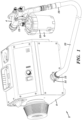
- FIG 1 is an isometric view of an HVLP system 2.
- the system comprises a gun 4, a fluid reservoir 6, an air supply unit 8, a fitting 14, and a hose 10.
- the gun 4 is supplied paint by the reservoir 6 through neck 12.
- the air supply unit 8 contains various components for providing and controlling pressurized air suitable for HVLP spraying.
- the pressurized air is conveyed through the fitting 14 of the air supply unit 8, through the hose 10, and to the gun 4.
- the air flow can be approximately 2832 liters per minute (100 cubic feet per minute).
- the air supply unit 8 includes a fitting 14 which attaches to a fitting 15 on the first end of the hose 10 (alternatively the fitting 14 attaches to another intermediary fitting that attaches to the fitting 15 of the hose 10).
- the fittings 14, 15 can connect with one another by a threaded or quick disconnect interface, amongst other options.
- the hose 10 may be a 2.54 cm (1 inch) outer diameter hose with a bore size of at least 1.27 cm (1/2 inch) (e.g., 2.23 cm (7/8 inch) inner diameter), in some embodiments, however other sizes are possible.
- the hose 10 may be at least 4.57 m (15 feet) long, and is preferably 6.10 m (20 feet) in some embodiments.
- the hose 10 can be formed from a flexible material, such as polymer or rubber.
- the hose 10 can be a corrugated tube, as shown in Fig, 1 .
- a fitting 16 on the second end of the hose is attached to the gun 4 (alternatively the fitting 16 attaches to another intermediary fitting that attaches to the gun 4).
- the fitting 16 can be of a swivel, quick disconnect type for attaching to the gun 4.
- the gun 4 is supplied paint by the reservoir 6 through neck 12.
- the gun 4 can use the pressurized air from the air supply unit 8, as conveyed by the hose 10, in multiple ways.
- the pressurized air propels the paint from the gun 4 as an atomized spray to paint various surfaces.
- the gun 4 can route some of the pressurized air through tube 18 to the reservoir 6, the pressurized air forcing the paint within the reservoir 6 up the neck 12 and into the gun 4.
- a gravity feed or other type of paint feed may alternatively be used in various embodiments, thus not requiring pressurized air to be supplied to the reservoir 6.
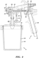
- Fig. 2 is a cross-sectional view of the gun 4 and the reservoir 6.
- the gun 4 includes a handle 20.
- the gun 4 includes a port 21 which mechanically connects with fitting 16 to make a sealed, pneumatic connection.
- the pressurized air supplied by the hose 10 flows through a channel located in the handle 20 and further into the interior of the gun 4.
- the gun 4 includes a trigger 22.
- the trigger 22 is mechanically connected to a needle 26.
- the needle 26 is an elongated metal rod.
- the trigger 22 is actuated by backward movement, which is toward the handle 20.
- the trigger 22 is unactuated or released by forward movement, which is away from the handle 20, and which can be driven by spring 29.
- Movement of the trigger 22 between actuated and unactuated states correspondingly moves the needle 26 backwards and forwards within the gun 4.
- the needle 26 seals two valves, whereby backward movement of the needle 26 opens the valves and forward movement of the needle 26 closes the valves.
- the first valve 30 comprises a shoulder or other enlarged portion in the needle 26 engaging an annular seat 31. The first valve 30 is normally closed but opens when the trigger 22 is actuated and the needle 26 is moved backwards, allowing the pressurized air in the channel in the handle 20 to flow into a front body portion 34 of the gun 4.
- the engagement between the shoulder or other enlarged portion in the needle 26 and the annular seat 31 prevents pressurized air in the channel in the handle 20 from flowing into a front body portion 34 of the gun 4.
- the second valve is formed by the front end of the needle 26 interfacing with the nozzle piece 28, the valve being opened by backward movement of the needle 26.
- the first valve 30 When the first valve 30 is opened, some of the pressurized air coming into the front body portion 34 flows through the tube 18 into the reservoir 6, which is used to drive paint from the reservoir 6 through the neck 12 that connects the reservoir 6 to the gun 4 and into a paint channel 35 located within the front body portion 34 of the gun 4.
- the paint channel 35 is coaxial with the needle 26.
- the reservoir 6 includes a cup 32.
- the cup 32 can be formed from a polymer or a metal.
- the cup 32 is rigid.
- the cup 32 contains a liner 36.
- a lid 38 fits over liner 36 and the cup 32.
- the liner 36 can contain paint. The liner 36 collapses upwards toward the neck 12 to force the paint up the neck 12 and into the paint channel 35 for spraying.
- the paint is forced upwards toward and through the neck 12 because the pressurized air that traveled through the tube 18 is introduced into the sealed space between the inside of the cup 32 and the outside of the liner 36 (e.g., at 0.2 - 0.69 bar (3 -10 pounds per square inch)), thereby making the pressure outside the liner 36 greater than inside the liner 36 and collapsing the liner 36 while pushing the paint upwards.
- the backward movement of the needle 26 due to actuating the trigger 22 also opens the valve formed between the front end of the needle 26 interfacing with the nozzle piece 28, the paint that was driven into the paint channel 35 from the neck 16 mixes with the pressurized air near the nozzle 24 and is propelled out of the gun 4 as an atomized spray.
- the back end of the nozzle piece 28 aligns with the paint channel 35 such as that paint moving through the paint channel 35 moves into and through the nozzle piece 28 to be mixed with the pressurized air for spraying from the nozzle 24.
- the illustrated embodiment uses a collapsible liner 36
- various other embodiments may not include a liner 36.
- the paint may reside directly in the cup 32.
- the gun 4 may be modified to invert the cup 32 above the gun 4 in a cup-over arrangement so that the flow of paint from the reservoir is gravity assisted.
- the tube 18, the liner 36, and supply of pressurized air into the cup 32 may be omitted.
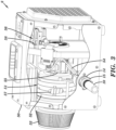
- Fig. 3 shows a sectional view of the air supply unit 8.
- the air supply unit 8 includes a blower 51, control circuitry 56, a sensor 58, and the fitting 14, in the illustrated embodiment.
- the air supply unit 8 includes a housing 50, which can be a metal or plastic box.
- the housing 50 can fully or partially contain the blower 51, the control circuitry 56, the sensor 58, and the fitting 14.
- the fitting 14 is shown to be both partially inside and outside of the housing 50 by extending through a wall of the housing 50, however the fitting 14 may instead be located entirely inside or entirely outside of the housing 50.
- the fitting 14 connects with the fitting 15 of the hose 10 to create an airtight seal therebetween.
- the HVLP air output by the blower 51 when the blower 51 is operating at a sustained level, can have a pressure in the range of 0.14 - 0.69 bar (2-10 pounds per square inch).
- the pressure of the HVLP air at the nozzle 24 can be in the range of 0.14 - 0.69 bar (2-10 pounds per square inch), however 0.21 - 0.48 bar (3-7 pounds per square inch) is typical.
- the rate of airflow from the blower 51 depends on the degree of restriction in the inlet 53, and the degree of restrictions downstream from the blower 51, amongst other factors.
- HVLP spraying is typically limited to a pressure of 0.69 bar (10 pounds per square inch) or less while having no flow rate limits, although the mass of flowing air must be sufficient to atomize paint and therefore is dependent on the type of paint being used.
- the blower 51 sucks in ambient air through inlet 53, shown to include an air filter, compresses and accelerates the air within housing 52, and blows the air out of the fitting 14.
- a sectional view of the housing 52 is shown, revealing blades 57 which are rotated by the motor 55 to compress and move air.
- the motor 55 is an electrical motor that rotates based on input of electrical power.
- the motor 55 may be a rotor-stator motor, for example.
- the power output to the motor 55 can be either direct current or alternating current, depending on the type of motor.
- the air may be compressed and accelerated by any type of fan, impeller, turbine, or other type of bladed component being rotated within the housing 52 by motor 55.
- the blower 51 is not a positive displacement pump, but rather is a centrifugal pump.
- Power output to the motor 55 is regulated by control circuitry 56.
- the control circuitry 56 increases and decreases power output to the turbine 51 by increasing and decreasing power output to the motor 55 to cause the rotational output of the motor 55 to start, stop, speed up from a first non-zero level to a second higher level, and slowdown from the second higher level to the first non-zero level.
- the air flow output through the fitting 14 by the blower 51 flows into the hose 10 and through to the gun 4.
- upstream as used herein means directionally closer to the blower 51 and the term “downstream” as used herein means directionally closer to the gun 4 along the flow path of pressurized air moving from the blower 51 to the gun 4.
- the fitting 14 can be formed from metal and/or polymer. As shown in Fig. 3 , a first end of a tube 54 is connected to the fitting 14. The tube 54 extends within the housing 50. A second end of the tube 54 connects with sensor 58.
- the sensor 58 is mounted on a board with control circuitry 56 in the illustrated embodiment, however the sensor 58 may not be located remote from the board supporting the control circuitry 56 in various other embodiments. For example, the sensor 58 may be mounted in the fitting 14, hose 10, or gun 2.
- the sensor 58 can output a signal indicative of an air parameter, such as a signal indicative of air pressure or air flow.
- the sensor 58 outputs a signal indicative of air pressure within the tube 54, which being tapped from the fitting 14, is indicative of air pressure within the fitting 14.
- the sensor 58 can be a digital or analog, air pressure or flow sensor that outputs a signal indicative of air pressure or flow.
- the sensor 58 can be a force collector-type transducer (e.g., a piezoelectric/resistive strain gauge or capacitive/electromagnetic transducer).
- the sensor 58 can be a microelectromechanical (MEMS) sensor.
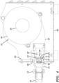
- Fig. 4 is a sectional view of the air supply unit 8 that shows a cross-section of the fitting 14.
- the blower 51 is shown to include an outlet 67 which directs the HVLP air flow into the fitting 14.
- the fitting 14 may be the outlet of the blower 51.
- the fitting 14 contains a valve 68.
- the valve 68 is shown as a check valve. More specifically, the valve 68 is shown as a poppet-type valve, however other types of valves, such as a ball-type valve, can instead be used.
- the valve 68 is mechanically activated by air pressure, however an electrically controlled valve, such as a solenoid valve, controlled by the control circuitry 56 to open and close whenever the blower 51 turns on or off, respectively, can be substituted, amongst other options.
- the valve 68 includes a seat 64 and a poppet 62, the poppet 62 having a gasket 70 that is pushed against the seat 64 by a spring 60 to prevent airflow in the upstream direction when the valve 68 is closed.
- the poppet 62 seals against the seat 64 when there is no or minimal pressure differential between the upstream and downstream sides of the valve 68.
- the valve 68 when closed, prevents pressurized air within the hose 10 (as well as pressurized air that is within the fitting 14 but downstream of the valve 68 and within the tube 54) from moving back upstream past the seal between the seat 64 and the gasket 70 of the poppet 62.
- the poppet 62 lifts from the seat 64 when pressurized air, generated by the blower 51, pushes against poppet 62 to overcome the spring 60.
- the valve 30 in the gun 4 is not open (due to the trigger 22 not being pulled)
- the air pressure downstream of the valve 68 may equalize with the air pressure upstream of the valve 68, because the air within the hose 10 has no place else to flow, causing the valve 68 to close.
- the air within the hose 10 and otherwise downstream of the fitting 14 flows into the gun 4, at least temporarily lowering the pressure downstream of the valve 68 and allowing the pressured air upstream of the valve 68 to push against poppet 62 to overcome the spring 60.
- the fitting 14 includes one or more ports 59 what extend from inside the fitting 59, upstream of the valve 68, to outside of the fitting 14 yet within the housing 50.
- the one or more ports 59 allow the HVLP air flow to exit the fitting 14, such as when the valve 68 is closed.
- the fitting 14 includes channel 66 that taps the fitting 14 downstream of the valve 68. In particular, the channel 66 taps the fitting 14 downstream of the seal between the seat 64 and the gasket 70 of the poppet 62.
- the tube 54 is in fluid communication with the channel 66 to allow the air parameter to be measured by sensor 58, the measured air parameter representing or otherwise indicating the level of the air parameter within the fitting 14 and/or downstream of the valve 68.
- the valves 30, 68 when both closed, trap pressurized air inside each of the gun 4 (specifically, upstream of the valve 30), the hose 10 (including within fittings 15, 16), and the fitting 14 (e.g., downstream of the valve 68 in the case that the valve 68 is located with the fitting 14).
- the contained volume between the two valves 30, 68 is referred to herein as the pneumatic circuit.
- the hose 10 may expand while under pressure from the blower 51 to increase its volume to accommodate more pressurized air.
- the tube 54 in extending from the fitting 14 to the sensor 58, is a sealed, dead-end side branch of the pneumatic circuit. As such, the sensor 58 outputs a signal indicative of a parameter within the pneumatic circuit.
- the pneumatic circuit serves as an accumulator by containing a reservoir of pressurized air that is released upon the opening of the valve 30. Most or essentially all of the volume of trapped air of the pneumatic circuit is located within the hose 10.
- the hose 10 can contain enough pressurized air, even at the low pressure used in HVLP spraying, to immediately resume spraying when the triggered 22 is actuated to open valve 30 to release pressurized air within the hose 10 into the front body portion 34 of the gun 4, even when the blower 51 is just restarting (i.e. not rotating and/or still accelerating to a normal rotational speed).
- the valve 68 is located upstream from the hose 10, allowing the full volume of the hose 10 to be utilized as an air accumulator.
- the valve 68 may be immediately upstream of the hose 10 (e.g., within 2.54 - 7.62 cm (1-3 inches) from the fitting of the hose 10).
- no separate accumulator other than the gun 4, hose 10, and fittings 14-16 may be used in some embodiments.
- the system may not have a chamber within or outside of the air supply unit 8 to store a reservoir of pressurized air for release into the front body portion 34 of the gun 4 or otherwise through the nozzle 24.
- no separate accumulator (other than the pneumatic circuit) may be used downstream of the valve 68.
- a separate accumulator is used (e.g., a metal tank in fluid connection with the fitting 14) and connects to the pneumatic circuit between the valves 30, 68.
- HVLP sprayer 51 It is not desirable to run the blower 51 at all times during a spraying project. Ordinarily, the user is not always spraying, and there may be prolonged periods of non-use between instances of spraying on the jobsite. An operator of an HVLP sprayer typically has frequent interruptions to their actual spraying of coatings. Users may readjust their work piece, configure taping or masking on the work piece or within their work areas, or focus on a different task. Conventional HVLP spray systems only turn off the air source when the power to the entire system is turned off by a manual external switch, leaving the system unpressurized and not ready for resumption of spraying before the motor 55 starts and accelerates to a speed sufficient for generating HVLP air adequate for spraying.
- the user in a conventional HVLP spray system, the user must walk back to the main unit to turn it on and off, even if the user is spraying remotely via a hose. While running the blower 51 at all times provides plenty of pressurized air, even much more so than needed, such constant operation prematurely wears the blower 51, wastes energy, generates excessive heat, and creates excessive noise in the jobsite environment. To avoid excessive operation of the blower 51, the power to blower 51 can be reduced, including by being switched off, by control circuitry 56 when the user is not actuating the trigger 22 and thus not actively spraying.
- Pressured air trapped in pneumatic circuit can be used for immediate resumption of spraying even if power to the blower 51 is temporarily reduced upon actuation of the trigger 22, including if the blower 51 is restarting from a dead stop and thus still accelerating when the trigger 22 is actuated and the user expects to be spraying.
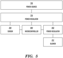
- Fig. 5 is a schematic of the electronic components which control the operation of the HVLP system 2.
- the microcontroller 80 and secondary power regulator 82 components can comprise the control circuitry 56.
- the power source 76 can be an electrical power cord supplying electrical power from a conventional wall outlet.
- the power source 76 can alternatively be a battery, amongst other options.
- the power regulator 78 can convert (e.g., alternating current to direct current via one or more diodes or other components) and regulate (e.g., lower the voltage via one or more resistors or other components) the electrical energy from the power source 76 and deliver power along multiple channels to power different components.
- the power regulator 78 supplies power to the sensor 58, the microcontroller 80, and the secondary power regulator 82, however power could additionally or alternatively be supplied to any other component of the HVLP system 2.
- the microcontroller 80 regulates power to the blower 51.
- the microcontroller 80 turns the blower 51 on and off, and in some cases can decrease the supply of electrical energy to the blower 51 to a non-zero level and/or can increase the supply of electrical energy to the blower 51 from a non-zero level to a higher level.
- the secondary power regulator 82 is operated by the microcontroller 80, the secondary power regulator 82 regulating power to the blower 51 as controlled by the microcontroller 80.
- the secondary power regulator 82 can interrupt the supply of electrical energy to the motor 55 of the blower 51. As determined by the microcontroller 80, the secondary power regulator 82 can close to allow electrical energy to flow to the blower 51 and open to block electrical energy from flowing to the blower 51.
- the secondary power regulator 82 can be an electronic switch operated by the microcontroller 80.
- the secondary power regulator 82 can be a solid state relay.
- the secondary power regulator 82 can be a semiconductor device such as a bidirectional triode thyristor (i.e. a TRIAC) or an insulated-gate bipolar transistor (i.e. a IGBT).
- the secondary power regulator 82 can additionally or alternatively include a variable resistor or other electrical component for selectively increasing and reducing power to the blower 51 without necessarily stopping current flow (i.e. is not limited to just open and closed circuit states).
- the microcontroller 80 can include, among other things, a processor and memory storing program instructions thereon which, when executed by the processor, perform or cause to be performed any of the operations referenced herein, such as part of a firmware or software program. While microcontroller 80 and secondary power regulator 82 are shown and/or referenced as being a part of the control circuitry 56, the control circuitry 56 can include different components while still being configured to perform the operations described herein. The secondary power regulator 82 can be integrated into the microcontroller 80 in some embodiments. In summary, the control circuitry 56 comprises one or more electrical components, such as the microcontroller 80, which regulate power output to the blower 51 to selectively increase and reduce power output to the blower 51.
- the sensor 58 outputs a pressure reading, indicative of the air pressure within the pneumatic circuit, to the microcontroller 80.
- the microcontroller 80 monitors the pressure and, based on changes in the pressure, controls the operation of the blower 51.
- the microcontroller 80 increases power output to the blower 51 when the measured pressure is below a first threshold, which may include starting to deliver power to the blower 51.
- the first threshold is an activation threshold.
- the first threshold can be less than 0.14 bar (2 pounds per square inch), or can be 0.10 bar (1.5 pounds per square inch) (all pressure values are relative to atmospheric pressure), for example.
- Increasing power output to the blower 51 when the measured pressure is below the first threshold may correspond to a condition in which the whole HVLP system 2 has just been turned on (e.g., by actuation of an on/off switch on the housing 50 or by being plugged into a standard electrical wall outlet) and the pressure in the pneumatic circuit is at zero or an atmospheric level.
- the microcontroller 80 causes power to be output to the blower 51 to charge up the pneumatic circuit with pressurized air, even if the trigger 22 is not actuated.
- the microcontroller 80 continues to monitor the pressure in the pneumatic circuit, which in this case is increasing.
- the signal output by the sensor 58 is indicative of whether the trigger 22 is actuated.
- the air pressure measured by the sensor 58 indicates that the trigger 22 is actuated by being at a relatively low and/or decreasing level corresponding to the pneumatic circuit emptying and not trapping air (e.g., at 0.34 bar (5 pounds per square inch) or below), and indicates that the trigger 22 is not actuated by being at a relatively high and/or increasing level corresponding to the pneumatic circuit trapping air (e.g., at 0.55 bar (8 pounds per square inch) or above).
- the control circuitry 56 can monitor the signal output by the sensor 58 and compare to one or more thresholds to assess whether the trigger 22 is actuated or not and determine whether to change or maintain the power level output to the blower 51.
- the microcontroller 80 causes a decrease in power output to the blower 51 based on the pressure rising above a second threshold.
- Such decrease in power output may include stopping power output to the blower 51.
- the second threshold can be a deactivation threshold.
- the second threshold can be in the range of 0.48 - 0.69 bar (7-10 pounds per square inch), or can be 0.48 bar (7 pounds per square inch), or can be 0.62 bar (9 pounds per square inch), amongst other options.
- the second threshold can represent a state in which the pneumatic circuit is charged with pressurized air and the air is not escaping the pneumatic circuit (e.g., by the trigger 22 not being actuated, thus keeping valve 30 closed).
- the microcontroller 80 can either immediately reduce power to the blower 51 (e.g., by partially or completely cutting power to the blower 51) or can start a timer while maintaining the same power output to the blower 51.
- the counting is performed by the microcontroller 80.
- the timer can be five, ten, or twenty seconds in duration, amongst other options. This time setting can be adjusted to shorter or longer durations (e.g., by a user input control, which can be a dial or button interface) to best suit the user's preferences and application of the unit.
- the blower 51 When a timer is used in association with the second threshold, the blower 51 continues to be powered during the counting of the timer at the same level as output to the blower 51 before the pressure level was recognized to cross the second threshold. This continued operation of the blower 51 may continue to build pressure within the pneumatic circuit or may just exhaust surplus pressurized air into the housing 50 of the air supply unit 8.
- the low pressure nature of HVLP blower 51 means that the air pressure within the accumulator may equal the air pressure output by the blower 51 within a few seconds (e.g., 2 seconds) and before the timer expires.
- the purpose of the timer is to keep the blower 51 operating in case the user resumes spraying shortly after having released the trigger 22, and in which case frequent stopping and starting of the blower 51 is not desired.
- the time in which a user retriggers to resume spraying is most likely to be soon after having released the trigger 22 (e.g., within 20 seconds).
- the blower 51 is left operating during the counting of the timer so that the system continues to output pressurized air in case of retriggering by the user.
- the control circuitry 56 continues to maintain the same level of power output to the blower 51 (or otherwise does not decrease power to the blower 51) while canceling the current count of the timer and/or otherwise terminating any sequence that may have been started to reduce power to the blower 51.
- the pressure within the pneumatic circuit is usually below the second (deactivation) threshold while the trigger 22 is actuated and the valve 30 is open such that the measured pressure stays below, and does not cross the second threshold so long as the user continues to keep the trigger 22 actuated to continue spraying.
- the second threshold is set at such a level that the pressure within the pneumatic circuit will rise above the second threshold when closure of the valve 30, due to the trigger 22 no longer being actuated, stops the downstream release of pressurized air from the pneumatic circuit, thereby causing the control circuitry 56 to either immediately reduce power to the blower 51 or start the timer that may lead to reducing power to the blower 51 so long as the pressure remains above the second threshold and/or otherwise stable.
- the microcontroller 80 controls the secondary power regulator 82 to reduce the flow of electrical energy to the blower 51.
- the blower 51 can then remain stopped or at a lowered speed while the pneumatic circuit remains charged with air trapped between valves 30, 68, the trapped air ready to supply the gun 4 for spraying once the trigger 22 is again actuated.
- the accumulated volume of pressurized air in the pneumatic circuit flows through the opened valve 30 to spray paint.
- the pressure within the pneumatic line as measured by the sensor 58, will drop as the valve 30 opens.
- a measured drop in the pressure level can initiate an increase in power output to the blower 51 by the microcontroller 80 in one or more ways, as detailed below. If the blower 51 was already on or otherwise operating with non-reduced power when the trigger 22 was reactuated, then blower 51 will continue to be supplied with the same level of power, as controlled by microcontroller 80, to provide pressurized air into the pneumatic circuit.
- the microcontroller 80 can be configured to increase power output to the blower 51 upon detecting the monitored pressure level dropping below a threshold (e.g., the first threshold, the second threshold, or a third threshold that is set at a pressure level between the first and second thresholds).
- a threshold e.g., the first threshold, the second threshold, or a third threshold that is set at a pressure level between the first and second thresholds.
- the microcontroller 80 can be configured to increase power output to the blower 51 upon detecting any drop in monitored pressure greater than a predetermined amount.
- the microcontroller 80 can be configured to increase power output to the blower 51 upon detecting a decrease in measured pressure greater than a predetermined amount, such as 0.21 bar (3 pounds per square inch).
- a predetermined amount such as 0.21 bar (3 pounds per square inch).
- the microcontroller 80 can be configured to monitor the rate of change of the monitored pressure over time (e.g., by taking the derivate of the pressure signal pattern) and increase power output to the blower 51 if a rate of change of greater than a predetermined amount (e.g., 6.89 mbar (0.1 pounds per square inch) per fifty milliseconds) is detected. It is noted that one or multiple of the above criteria can be monitored and used to initiate an increase in power output to the blower 51, the power output being increased when any one of the criteria is met.
- Reducing power to the blower 51 based on a sensed air parameter can include either lowering the power from a first level to a second non-zero level that is lower than the first level or stopping the flow of power to the blower 51, depending on how the control circuitry 56 in the particular embodiment is configured. Lowering the power to the second non-zero level allows the blower 51 to still rotate and be poised to quickly accelerate to its previous air flow output at the first level while reducing wear, heat generation, and noise while being supplied at the second non-zero level.
- increasing power to the blower 51 based on a sensed air parameter can include resuming delivery of power to the blower 51 after a state in which no power was being output to the blower 51 or can include changing power output from the second non-zero level back to the first level.
- accelerating the blower 51 refers to increasing the rotational speed of the fan, turbine, impeller, or other bladed component of the blower 51 to increase its output of HVLP air.
- the blower 51 is accelerated by increasing the power output to the motor 55 of the blower 51.
- the blower 51 may be accelerated from a dead stop or accelerated from a first non-zero speed to a second speed that is greater than the first speed.
- control circuitry 56 directs power to the blower 51 to move HVLP air through the pneumatic circuit and into the gun 4 as long as the trigger 22 remains actuated.
- the flow of air through the pneumatic circuit will be stopped by closure of valve 30. This will result in an increase in pressure within the pneumatic circuit.
- the valve 68 will close as the pressure gradient upstream and downstream from the valve 68 equalizes due to a lack of continuous flow through the pneumatic circuit.
- the control circuitry 56 Based on the signal output by the sensor 58 indicative of the pressure within the pneumatic circuit, the control circuitry 56 will recognize that the pressure within the pneumatic circuit has crossed a threshold pressure (e.g., the first, second, or third threshold discussed above). The control circuitry 56 will then initiate the counting of a timer. The timer will begin to count to a predetermined value (e.g., 10 seconds) and then stop outputting power to the blower 51 if the pressure is maintained above the threshold and/or some other pressure threshold is not breached while the timer is counting to the predetermined value.
- a threshold pressure e.g., the first, second, or third threshold discussed above.
- the control circuitry 56 will then initiate the counting of a timer. The timer will begin to count to a predetermined value (e.g., 10 seconds) and then stop outputting power to the blower 51 if the pressure is maintained above the threshold and/or some other pressure threshold is not breached while the timer is counting to the predetermined value.
- the blower 51 shutoff sequence will be canceled and the blower 51 will continue to be powered at the same level at least until the next time the pressure within the pneumatic circuit crosses the threshold pressure. If the counting completes with the pressure being maintained above the threshold and/or some other pressure threshold is not breached while the timer is counting to the predetermined value, then the control circuitry 56 will turn off power to the blower 51 and the pneumatic circuit will hold pressure, the hose 10 functioning as an accumulator ready to supply pressurized air when the trigger 22 is again actuated.
- the valve 30 When the user pulls the trigger 22 to an actuated state, the valve 30 will open to allow pressurized air trapped within the pneumatic circuit to flow through the gun 4 to spray paint even though the blower 51 is off (or accelerating).
- the control circuitry 56 Upon the release of pressurized air from the pneumatic circuit while the blower 51 is off (or accelerating), the control circuitry 56 will recognize that the pressure within the pneumatic circuit has dropped below a threshold pressure (e.g., the first, second, or third threshold discussed above) and will immediately resume output of power to the blower 51.
- a threshold pressure e.g., the first, second, or third threshold discussed above
- the valve 68 re-open due to the upstream pressure being greater than the downstream pressure and the system will once again run in a sustained spraying mode so long as the trigger 22 remains actuated. It is noted that the measured pressure rising above a threshold indicates that the pressure has increased while the measured pressuring falling below a threshold indicates that the pressure has decreased.
- the senor 58 is an air flow sensor placed in the pneumatic circuit, such as within the air flow path with fitting 14.
- the air flow sensor can be a hot wire mass airflow sensor or a spring-loaded air flap attached to a potentiometer, amongst other options.
- the air flow sensor outputs a signal to the microcontroller 80 indicative of the mass of air flow in the pneumatic circuit.
- the level of air flow as indicated by the signal can be used to increase and decrease power output to the blower 51 by the control circuitry 56 in the same manner as when a pressure sensor output the signal as discussed herein.
- the conditions for increasing and decreasing power to the blower 51 as described based on pressure as described herein can apply to a system using an airflow sensor instead of a pressure sensor, wherein low or no air flow corresponds to a low or no pressure condition (in which the control circuitry 56 increases power to the blower 51) and high air flow corresponds to a high pressure condition (in which the control circuitry 56 decreases power to the blower 51). Therefore, all options discussed herein for a blower 51 modulated by an air pressure signal can be applied similarly in a system modulated by an air flow signal.
- the benefits of this designs presented herein include the ability to achieve good spray atomization due to the use of the hose 10 as an accumulator to provide instant positive air flow when the trigger 22 is first actuated even if the blower 51 is not powered, is operating at a low power setting, and/or is accelerating to a higher speed.
- the transition from using trapped air in the pneumatic circuit for spraying to using pressurized air continuously flowing from the blower 51 (once fully accelerated) for spraying can be seamless to the user. Allowing the blower 51 to stop or operate at a low power setting when the trigger 22 is not actuated minimizes motor wear, energy consumption, heat generation, and noise.
Landscapes
- Physics & Mathematics (AREA)
- Fluid Mechanics (AREA)
- General Physics & Mathematics (AREA)
- Engineering & Computer Science (AREA)
- Automation & Control Theory (AREA)
- Nozzles (AREA)
- Application Of Or Painting With Fluid Materials (AREA)
Claims (16)
- Pulvérisateur (2) comprenant :une unité d'alimentation en air (8) comprenant un moteur (55), l'unité d'alimentation en air (8) étant configurée pour produire un débit volumique élevé d'air sous pression par le fonctionnement du moteur (55) ;un tuyau (10) ayant une première extrémité et une deuxième extrémité, la première extrémité recevant l'air sous pression délivré par l'unité d'alimentation en air (8) ;un pistolet pulvérisateur (4) ayant une gâchette (22) et une première soupape (30), la deuxième extrémité du tuyau (10) étant raccordée au pistolet pulvérisateur (4), dans lequel l'actionnement de la gâchette (22) amène la première soupape (30) à s'ouvrir et le pistolet pulvérisateur (4) à pulvériser du produit fluide à l'aide de l'air sous pression provenant du flexible (10) ;une deuxième soupape (68) située en amont du tuyau (10) et à travers laquelle au moins une partie de l'air sous pression délivré par l'unité d'alimentation en air (8) s'écoule ;un capteur (58) qui émet un signal indicatif d'un paramètre de l'air sous pression qui est en aval de la deuxième soupape et en amont de la première soupape ; etun circuit de commande (56) qui reçoit le signal et régule la puissance de sortie vers le moteur (55),dans lequel un volume d'air sous pression est piégé dans le tuyau (10) par les première et deuxième vannes (30, 68) lorsque la première et les deuxièmes vannes sont fermées, et le volume de l'air sous pression est utilisé par le pistolet pulvérisateur (4) pour pulvériser par l'actionnement de la gâchette (22), caractérisé en ce quele circuit de commande (56) est configuré pour réduire l'alimentation électrique de sortie vers le moteur (55) sur la base du signal indiquant que le paramètre de l'air sous pression a augmenté, et augmenter la puissance de sortie électrique vers le moteur (55) sur la base du signal indiquant que le paramètre de l'air sous pression a diminué ;le volume d'air sous pression piégé dans le tuyau est suffisant pour reprendre immédiatement la pulvérisation alors que la première vanne est ouverte et que la deuxième vanne est fermée.
- Pulvérisateur (2) selon la revendication 1, dans lequel le capteur (58) est un capteur de pression.
- Pulvérisateur (2) selon l'une ou l'autre des revendications 1 ou 2, dans lequel le signal est indicatif d'un paramètre de l'air sous pression lorsque l'air sous pression est soit piégé soit circulant entre les première et deuxième vannes (30, 68) .
- Pulvérisateur (2) selon une quelconque des revendications précédentes, dans lequel le capteur (58) est exposé à de l'air sous pression via un tube (54) qui part d'un circuit pneumatique entre les première et deuxième vannes (30, 68).
- Pulvérisateur (2) selon une quelconque des revendications précédentes, dans lequel la deuxième soupape (68) est située à l'intérieur d'un raccord auquel le tuyau (10) se fixe.
- Pulvérisateur (2) selon une quelconque des revendications précédentes, dans lequel la deuxième soupape (68) est un clapet anti-retour.
- Pulvérisateur (2) selon une quelconque des revendications précédentes, dans lequel la première soupape (30) est située à l'intérieur d'un corps du pistolet pulvérisateur (4).
- Pulvérisateur (2) selon une quelconque des revendications précédentes, dans lequel l'unité d'alimentation en air (8) comprend une soufflante (51) .
- Pulvérisateur (2) selon une quelconque des revendications précédentes, dans lequel, en réaction à l'actionnement de la gâchette (22), le volume d'air sous pression qui était piégé dans le tuyau (10) est libéré dans le pistolet pulvérisateur (4) et utilisé pour pulvériser du fluide tandis que le circuit de commande (56) augmente l'alimentation électrique délivrée au moteur (55) pour accélérer le moteur (55) afin de réalimenter en air sous pression le tuyau (10) .
- Pulvérisateur (2) selon une quelconque des revendications précédentes, dans lequel le circuit de commande (56) est configuré pour réduire l'alimentation électrique délivrée au moteur (55) sur la base du signal indiquant que le paramètre de l'air sous pression a augmenté en : démarrant une minuterie pendant une durée prédéterminée, puis en réduisant l'alimentation électrique délivrée au moteur (55) si le signal indique que le paramètre n'a pas franchi un seuil pendant le comptage de la minuterie, mais sans réduire l'alimentation électrique délivrée au moteur (55) si le signal indique que le paramètre a franchi le seuil pendant le comptage de la minuterie.
- Pulvérisateur (2) selon une quelconque des revendications précédentes, dans lequel le circuit de commande (56) est configuré pour réduire l'alimentation en alimentation électrique du moteur (55) sur la base du signal indiquant que le paramètre a augmenté au-dessus d'un seuil en arrêtant la fourniture d'alimentation au moteur (55).
- Pulvérisateur (2) selon une quelconque des revendications précédentes, dans lequel le circuit de commande (56) est configuré pour augmenter l'alimentation électrique du moteur (55) sur la base du signal indiquant que le paramètre a diminué en dessous d'un seuil en reprenant la fourniture de l'alimentation du moteur (55).
- Pulvérisateur (2) selon une quelconque des revendications précédentes, comprenant en outre un réservoir de fluide (6) fixé au pistolet pulvérisateur (4) à partir duquel le pistolet pulvérisateur (4) aspire le fluide à pulvériser.
- Procédé de commande d'un pulvérisateur (2) comprenant de :fournir de l'alimentation à un moteur (55) d'une unité d'alimentation en air (8) sur la base d'un signal émis par un capteur (58), l'unité d'alimentation en air (8) produisant un débit volumétrique élevé d'air sous pression, l'air sous pression circulant dans un flexible (10) et à travers deux vannes (30, 68), les deux vannes étant respectivement situées en amont et en aval du flexible (10), le signal indiquant un paramètre de l'air sous pression qui se trouve entre les deux vannes ;réduire la puissance du moteur (55) sur la base du signal indiquant une augmentation d'un niveau du paramètre ;augmenter la puissance du moteur (55) sur la base du signal indiquant une diminution du niveau du paramètre ; etpulvériser du fluide à partir d'un pistolet de pulvérisation (4) en utilisant un volume d'air sous pression alors qu'une première vanne (30) des deux vannes est ouverte et la deuxième vanne (68) des deux vannes est fermée, le volume d'air sous pression ayant été préalablement piégé dans le tuyau (10) entre les deux vannes (30, 68) alors que les deux vannes étaient fermées et qu'une gâchette (22) du pistolet de pulvérisation (4) n'était pas actionnée, le volume d'air sous pression étant libéré du fait de l'actionnement de la gâchette (22) ouvrant la première soupape des deux soupapes (30, 68), dans lequel le pistolet (4) reçoit l'air sous pression du tuyau (10) et chacune des étapes de fourniture, de réduction et d'augmentation sont exécutées par un circuit de commande (56).
- Procédé selon la revendication 14, dans lequel le paramètre est la pression de l'air sous pression.
- Procédé selon l'une ou l'autre des revendications 14 ou 15, dans lequel l'étape de réduction de la puissance du moteur (55) de l'unité d'alimentation en air (8) sur la base du signal indiquant une augmentation du paramètre comprend de :démarrer une minuterie pendant une durée prédéterminée,démarrer la réduction de l'alimentation électrique délivrée au moteur (55) si le signal indique que la gâchette (22) n'a pas été actionnée pendant le comptage de la minuterie,ne pas réduire l'alimentation électrique délivrée au moteur (55) si le signal indique que la gâchette (22) a été actionnée pendant le comptage de la minuterie.
Applications Claiming Priority (3)
| Application Number | Priority Date | Filing Date | Title |
|---|---|---|---|
| US201662297917P | 2016-02-21 | 2016-02-21 | |
| US201762449078P | 2017-01-22 | 2017-01-22 | |
| EP17156992.4A EP3207997B1 (fr) | 2016-02-21 | 2017-02-20 | Système de pulvérisation basse pression à volume élevé et à la demande et méthode correspondante |
Related Parent Applications (2)
| Application Number | Title | Priority Date | Filing Date |
|---|---|---|---|
| EP17156992.4A Division EP3207997B1 (fr) | 2016-02-21 | 2017-02-20 | Système de pulvérisation basse pression à volume élevé et à la demande et méthode correspondante |
| EP17156992.4A Division-Into EP3207997B1 (fr) | 2016-02-21 | 2017-02-20 | Système de pulvérisation basse pression à volume élevé et à la demande et méthode correspondante |
Publications (2)
| Publication Number | Publication Date |
|---|---|
| EP3566780A1 EP3566780A1 (fr) | 2019-11-13 |
| EP3566780B1 true EP3566780B1 (fr) | 2023-07-05 |
Family
ID=58094331
Family Applications (2)
| Application Number | Title | Priority Date | Filing Date |
|---|---|---|---|
| EP19169553.5A Active EP3566780B1 (fr) | 2016-02-21 | 2017-02-20 | Système de pulvérisation basse pression à volume élevé et à la demande |
| EP17156992.4A Active EP3207997B1 (fr) | 2016-02-21 | 2017-02-20 | Système de pulvérisation basse pression à volume élevé et à la demande et méthode correspondante |
Family Applications After (1)
| Application Number | Title | Priority Date | Filing Date |
|---|---|---|---|
| EP17156992.4A Active EP3207997B1 (fr) | 2016-02-21 | 2017-02-20 | Système de pulvérisation basse pression à volume élevé et à la demande et méthode correspondante |
Country Status (4)
| Country | Link |
|---|---|
| US (2) | US10328442B2 (fr) |
| EP (2) | EP3566780B1 (fr) |
| CN (1) | CN107096660B (fr) |
| ES (2) | ES2954839T3 (fr) |
Families Citing this family (22)
| Publication number | Priority date | Publication date | Assignee | Title |
|---|---|---|---|---|
| ITFI20140032U1 (it) * | 2014-05-23 | 2015-11-23 | Hpm Eng S R L | Un condotto flessibile ad attacco rapido per un dispositivo di verniciatura a spruzzo |
| EP3566780B1 (fr) * | 2016-02-21 | 2023-07-05 | Graco Minnesota Inc. | Système de pulvérisation basse pression à volume élevé et à la demande |
| DK3485982T3 (da) * | 2017-11-21 | 2020-10-26 | Ppg Europe B V | Spray system og metode til at spraye |
| US12207607B2 (en) * | 2018-03-28 | 2025-01-28 | Omar Alravvi | Date palm pollinator and powder disperser for high trees |
| US11925949B1 (en) * | 2018-10-16 | 2024-03-12 | Optix Technologies, LLC | Fluid metering component and spraying apparatus thereof |
| DE102019001534A1 (de) * | 2018-11-06 | 2020-05-07 | Martin Ruda 1. UG (haftungsbeschränkt). | Farbbecher für eine Spritzpistole und Spritzpistole |
| AU2019445796B2 (en) * | 2019-05-10 | 2023-10-26 | Ppg Europe B.V | Spray system and method of spraying |
| JP6722963B1 (ja) * | 2020-03-13 | 2020-07-15 | 株式会社空間除菌 | 噴霧装置 |
| CN111451023B (zh) * | 2020-04-09 | 2021-04-13 | 广东博智林机器人有限公司 | 自动喷枪 |
| US20240091398A1 (en) * | 2020-07-22 | 2024-03-21 | Creative Elements Ny Llc | Multi-component variable control fragrance dispensing system apparatus |
| USD1037412S1 (en) * | 2021-01-13 | 2024-07-30 | Ideal Living, Llc | Paint sprayer |
| MX2023009375A (es) * | 2021-02-19 | 2023-08-17 | Dispensing Tech Bv | Sistema de dispensacion de producto que comprende una bomba accionada por motor, un dispositivo de dispensacion y un contenedor de producto. |
| US20220347497A1 (en) * | 2021-04-28 | 2022-11-03 | Ford Global Technologies, Llc | Methods of assembling personal air purifying respirators |
| BE1029935B1 (nl) * | 2021-11-18 | 2023-06-19 | Chemicar Europe Nv | Samenstel van een beker, liner en deksel voor een verfpistool |
| DE102021131184A1 (de) * | 2021-11-28 | 2023-06-01 | J. Wagner Gmbh | Verfahren zur Steuerung eines Gebläses an einem Sprühgerät |
| CN114042554B (zh) * | 2021-12-21 | 2022-08-05 | 南通日旭重工科技有限公司 | 虹吸式油漆喷枪 |
| WO2023183358A1 (fr) * | 2022-03-22 | 2023-09-28 | Black & Decker Inc. | Aérographe |
| US12560160B2 (en) * | 2022-10-07 | 2026-02-24 | Keco Inc. | Pump controller assembly |
| USD1050356S1 (en) * | 2023-01-10 | 2024-11-05 | Graco Minnesota Inc. | Spray gun |
| USD1069985S1 (en) * | 2023-01-10 | 2025-04-08 | Graco Minnesota Inc. | Spray gun system |
| US20250256293A1 (en) * | 2024-02-09 | 2025-08-14 | Wagner Spray Tech Corporation | Air source control for an air operated fluid sprayer |
| CN119368352B (zh) * | 2024-12-27 | 2025-05-27 | 宁波美志工具有限公司 | 一种旋转定位调节的喷水枪 |
Family Cites Families (29)
| Publication number | Priority date | Publication date | Assignee | Title |
|---|---|---|---|---|
| BE622426A (fr) * | 1961-09-15 | |||
| US3397739A (en) * | 1964-05-18 | 1968-08-20 | Sibany Mfg Corp | Heat exchange apparatus |
| US4854822A (en) * | 1988-08-24 | 1989-08-08 | Apollo Sprayers International, Inc. | Series impeller air pump for liquid sprayer |
| US5074467A (en) * | 1990-11-30 | 1991-12-24 | Geberth John Daniel | High volume low pressure spray painting system, method of operation and control system therefor |
| US5279461A (en) | 1991-09-03 | 1994-01-18 | Apollo Sprayers International, Inc. | Spray gun |
| US5320280A (en) * | 1992-06-19 | 1994-06-14 | Graco Inc. | Pneumatically controlled spraying system having a diaphragm-operated switch |
| US5429307A (en) | 1993-06-14 | 1995-07-04 | Apollo Sprayers International, Inc. | Dual air supply spray gun |
| US5711483A (en) * | 1996-01-24 | 1998-01-27 | Durotech Co. | Liquid spraying system controller including governor for reduced overshoot |
| US5772403A (en) * | 1996-03-27 | 1998-06-30 | Butterworth Jetting Systems, Inc. | Programmable pump monitoring and shutdown system |
| US6820824B1 (en) | 1998-01-14 | 2004-11-23 | 3M Innovative Properties Company | Apparatus for spraying liquids, disposable containers and liners suitable for use therewith |
| US7032839B2 (en) | 2003-12-30 | 2006-04-25 | 3M Innovative Properties Company | Liquid spray gun with manually separable portions |
| US8133034B2 (en) * | 2004-04-09 | 2012-03-13 | Regal Beloit Epc Inc. | Controller for a motor and a method of controlling the motor |
| US20050279865A1 (en) * | 2004-06-18 | 2005-12-22 | Innovative Developments, Llc | Fluid spraying system |
| US7350723B2 (en) * | 2004-06-28 | 2008-04-01 | Just A Simple Thing, Inc | Cordless, self-contained, handheld spray gun |
| US7410106B2 (en) | 2005-02-08 | 2008-08-12 | 3M Innovative Properties Company | Pressurized liquid supply assembly |
| DE102008000400A1 (de) * | 2008-02-25 | 2009-08-27 | Robert Bosch Gmbh | Transportables Farbspritzgerät |
| US7950598B2 (en) * | 2008-12-30 | 2011-05-31 | Graco Minnesota Inc. | Integrated flow control assembly for air-assisted spray gun |
| WO2011002885A1 (fr) | 2009-07-01 | 2011-01-06 | Printpack Illinois, Inc. | Filière thermoscellante avec éléments thermoscellants compressibles et procédés d'utilisation de celle-ci |
| CA2671500C (fr) * | 2009-07-10 | 2011-05-24 | Thomas Lemmer | Systeme et methode de regulation de pression pour moteur differentiel |
| US20110079654A1 (en) * | 2009-10-06 | 2011-04-07 | Jeffery Lynn Bailey | Irrigation evacuation system |
| US8850827B2 (en) * | 2010-03-05 | 2014-10-07 | Honeywell International Inc. | Control valve with radial seals |
| DE102010045708A1 (de) * | 2010-09-16 | 2012-03-22 | Andreas Stihl Ag & Co. Kg | Sprühgerät |
| EP2708592B2 (fr) * | 2012-09-14 | 2022-03-16 | The Procter & Gamble Company | Composition de traitement de tissu |
| US9132442B2 (en) * | 2012-11-10 | 2015-09-15 | Mi Yan | Diagnosis and controls of a fluid delivery apparatus with hydraulic buffer |
| US9599117B2 (en) * | 2013-03-14 | 2017-03-21 | John A. Darroch | Back pressure relief motor control for a non-bleeder turbine style HVLP spray gun |
| US9140153B2 (en) * | 2013-06-05 | 2015-09-22 | Ford Global Technologies, Llc | Engine system having a backflow valve and method for operation thereof |
| US9810128B2 (en) * | 2015-08-10 | 2017-11-07 | Fca Us Llc | Secondary air pump assembly |
| EP3566780B1 (fr) * | 2016-02-21 | 2023-07-05 | Graco Minnesota Inc. | Système de pulvérisation basse pression à volume élevé et à la demande |
| US10758933B2 (en) * | 2016-03-01 | 2020-09-01 | Carlisle Fluid Technologies, Inc. | Fluid regulation system |
-
2017
- 2017-02-20 EP EP19169553.5A patent/EP3566780B1/fr active Active
- 2017-02-20 EP EP17156992.4A patent/EP3207997B1/fr active Active
- 2017-02-20 ES ES19169553T patent/ES2954839T3/es active Active
- 2017-02-20 ES ES17156992T patent/ES2738561T3/es active Active
- 2017-02-20 US US15/437,019 patent/US10328442B2/en active Active
- 2017-02-21 CN CN201710093767.7A patent/CN107096660B/zh active Active
-
2019
- 2019-05-23 US US16/421,109 patent/US11806742B2/en active Active
Also Published As
| Publication number | Publication date |
|---|---|
| EP3566780A1 (fr) | 2019-11-13 |
| ES2954839T3 (es) | 2023-11-27 |
| EP3207997B1 (fr) | 2019-05-22 |
| CN107096660B (zh) | 2020-02-28 |
| EP3207997A1 (fr) | 2017-08-23 |
| US10328442B2 (en) | 2019-06-25 |
| CN107096660A (zh) | 2017-08-29 |
| US20170239675A1 (en) | 2017-08-24 |
| US20190275539A1 (en) | 2019-09-12 |
| ES2738561T3 (es) | 2020-01-23 |
| US11806742B2 (en) | 2023-11-07 |
Similar Documents
| Publication | Publication Date | Title |
|---|---|---|
| US11806742B2 (en) | On-demand high volume, low pressure spray system | |
| CN110076026B (zh) | 具有料斗的手持纹理喷枪 | |
| US12103027B2 (en) | Remote priming of texture sprayer | |
| US12162032B2 (en) | Sprayers, dispensers, and methods for using the same | |
| US11577282B2 (en) | Pressurized cleaning apparatus comprising a pressure generation unit | |
| KR20240158974A (ko) | 유체 분무기 | |
| CN104394998A (zh) | 静电喷射工具动力源 | |
| US10076760B2 (en) | Pneumatically powered foam sprayer | |
| US20150238986A1 (en) | Compressed air shutoff for an electrostatic spray tool power supply | |
| US11779947B2 (en) | Pressure cleaning device, method for operating a pressure cleaning device and method for detecting a hose attachment | |
| US10167641B2 (en) | Air control trigger for integrated handheld texture sprayer | |
| US20150330089A1 (en) | Pressure-assist hopper for integrated handheld texture sprayer | |
| US20120292339A1 (en) | Dispensing gun for a collapsible adhesive-filled container | |
| CN100455359C (zh) | 流体分配装置 | |
| US20250256293A1 (en) | Air source control for an air operated fluid sprayer |
Legal Events
| Date | Code | Title | Description |
|---|---|---|---|
| PUAI | Public reference made under article 153(3) epc to a published international application that has entered the european phase |
Free format text: ORIGINAL CODE: 0009012 |
|
| STAA | Information on the status of an ep patent application or granted ep patent |
Free format text: STATUS: THE APPLICATION HAS BEEN PUBLISHED |
|
| AC | Divisional application: reference to earlier application |
Ref document number: 3207997 Country of ref document: EP Kind code of ref document: P |
|
| AK | Designated contracting states |
Kind code of ref document: A1 Designated state(s): AL AT BE BG CH CY CZ DE DK EE ES FI FR GB GR HR HU IE IS IT LI LT LU LV MC MK MT NL NO PL PT RO RS SE SI SK SM TR |
|
| STAA | Information on the status of an ep patent application or granted ep patent |
Free format text: STATUS: REQUEST FOR EXAMINATION WAS MADE |
|
| 17P | Request for examination filed |
Effective date: 20200330 |
|
| RBV | Designated contracting states (corrected) |
Designated state(s): AL AT BE BG CH CY CZ DE DK EE ES FI FR GB GR HR HU IE IS IT LI LT LU LV MC MK MT NL NO PL PT RO RS SE SI SK SM TR |
|
| STAA | Information on the status of an ep patent application or granted ep patent |
Free format text: STATUS: EXAMINATION IS IN PROGRESS |
|
| 17Q | First examination report despatched |
Effective date: 20211029 |
|
| RIC1 | Information provided on ipc code assigned before grant |
Ipc: B05B 7/08 20060101ALN20221216BHEP Ipc: B05B 12/00 20180101ALI20221216BHEP Ipc: B05B 7/24 20060101ALI20221216BHEP Ipc: B05B 7/06 20060101ALI20221216BHEP Ipc: B05B 7/00 20060101AFI20221216BHEP |
|
| GRAP | Despatch of communication of intention to grant a patent |
Free format text: ORIGINAL CODE: EPIDOSNIGR1 |
|
| STAA | Information on the status of an ep patent application or granted ep patent |
Free format text: STATUS: GRANT OF PATENT IS INTENDED |
|
| RIC1 | Information provided on ipc code assigned before grant |
Ipc: B05B 7/08 19680901ALN20230109BHEP Ipc: B05B 12/00 19740701ALI20230109BHEP Ipc: B05B 7/24 19680901ALI20230109BHEP Ipc: B05B 7/06 19680901ALI20230109BHEP Ipc: B05B 7/00 19680901AFI20230109BHEP |
|
| INTG | Intention to grant announced |
Effective date: 20230130 |
|
| GRAS | Grant fee paid |
Free format text: ORIGINAL CODE: EPIDOSNIGR3 |
|
| GRAA | (expected) grant |
Free format text: ORIGINAL CODE: 0009210 |
|
| STAA | Information on the status of an ep patent application or granted ep patent |
Free format text: STATUS: THE PATENT HAS BEEN GRANTED |
|
| P01 | Opt-out of the competence of the unified patent court (upc) registered |
Effective date: 20230414 |
|
| AC | Divisional application: reference to earlier application |
Ref document number: 3207997 Country of ref document: EP Kind code of ref document: P |
|
| AK | Designated contracting states |
Kind code of ref document: B1 Designated state(s): AL AT BE BG CH CY CZ DE DK EE ES FI FR GB GR HR HU IE IS IT LI LT LU LV MC MK MT NL NO PL PT RO RS SE SI SK SM TR |
|
| REG | Reference to a national code |
Ref country code: CH Ref legal event code: EP |
|
| REG | Reference to a national code |
Ref country code: AT Ref legal event code: REF Ref document number: 1584327 Country of ref document: AT Kind code of ref document: T Effective date: 20230715 |
|
| REG | Reference to a national code |
Ref country code: DE Ref legal event code: R096 Ref document number: 602017071090 Country of ref document: DE |
|
| REG | Reference to a national code |
Ref country code: IE Ref legal event code: FG4D |
|
| REG | Reference to a national code |
Ref country code: NL Ref legal event code: FP |
|
| REG | Reference to a national code |
Ref country code: LT Ref legal event code: MG9D |
|
| REG | Reference to a national code |
Ref country code: ES Ref legal event code: FG2A Ref document number: 2954839 Country of ref document: ES Kind code of ref document: T3 Effective date: 20231127 |
|
| REG | Reference to a national code |
Ref country code: AT Ref legal event code: MK05 Ref document number: 1584327 Country of ref document: AT Kind code of ref document: T Effective date: 20230705 |
|
| PG25 | Lapsed in a contracting state [announced via postgrant information from national office to epo] |
Ref country code: GR Free format text: LAPSE BECAUSE OF FAILURE TO SUBMIT A TRANSLATION OF THE DESCRIPTION OR TO PAY THE FEE WITHIN THE PRESCRIBED TIME-LIMIT Effective date: 20231006 |
|
| PG25 | Lapsed in a contracting state [announced via postgrant information from national office to epo] |
Ref country code: IS Free format text: LAPSE BECAUSE OF FAILURE TO SUBMIT A TRANSLATION OF THE DESCRIPTION OR TO PAY THE FEE WITHIN THE PRESCRIBED TIME-LIMIT Effective date: 20231105 |
|
| PG25 | Lapsed in a contracting state [announced via postgrant information from national office to epo] |
Ref country code: SE Free format text: LAPSE BECAUSE OF FAILURE TO SUBMIT A TRANSLATION OF THE DESCRIPTION OR TO PAY THE FEE WITHIN THE PRESCRIBED TIME-LIMIT Effective date: 20230705 Ref country code: RS Free format text: LAPSE BECAUSE OF FAILURE TO SUBMIT A TRANSLATION OF THE DESCRIPTION OR TO PAY THE FEE WITHIN THE PRESCRIBED TIME-LIMIT Effective date: 20230705 Ref country code: PT Free format text: LAPSE BECAUSE OF FAILURE TO SUBMIT A TRANSLATION OF THE DESCRIPTION OR TO PAY THE FEE WITHIN THE PRESCRIBED TIME-LIMIT Effective date: 20231106 Ref country code: NO Free format text: LAPSE BECAUSE OF FAILURE TO SUBMIT A TRANSLATION OF THE DESCRIPTION OR TO PAY THE FEE WITHIN THE PRESCRIBED TIME-LIMIT Effective date: 20231005 Ref country code: LV Free format text: LAPSE BECAUSE OF FAILURE TO SUBMIT A TRANSLATION OF THE DESCRIPTION OR TO PAY THE FEE WITHIN THE PRESCRIBED TIME-LIMIT Effective date: 20230705 Ref country code: LT Free format text: LAPSE BECAUSE OF FAILURE TO SUBMIT A TRANSLATION OF THE DESCRIPTION OR TO PAY THE FEE WITHIN THE PRESCRIBED TIME-LIMIT Effective date: 20230705 Ref country code: IS Free format text: LAPSE BECAUSE OF FAILURE TO SUBMIT A TRANSLATION OF THE DESCRIPTION OR TO PAY THE FEE WITHIN THE PRESCRIBED TIME-LIMIT Effective date: 20231105 Ref country code: HR Free format text: LAPSE BECAUSE OF FAILURE TO SUBMIT A TRANSLATION OF THE DESCRIPTION OR TO PAY THE FEE WITHIN THE PRESCRIBED TIME-LIMIT Effective date: 20230705 Ref country code: GR Free format text: LAPSE BECAUSE OF FAILURE TO SUBMIT A TRANSLATION OF THE DESCRIPTION OR TO PAY THE FEE WITHIN THE PRESCRIBED TIME-LIMIT Effective date: 20231006 Ref country code: FI Free format text: LAPSE BECAUSE OF FAILURE TO SUBMIT A TRANSLATION OF THE DESCRIPTION OR TO PAY THE FEE WITHIN THE PRESCRIBED TIME-LIMIT Effective date: 20230705 Ref country code: AT Free format text: LAPSE BECAUSE OF FAILURE TO SUBMIT A TRANSLATION OF THE DESCRIPTION OR TO PAY THE FEE WITHIN THE PRESCRIBED TIME-LIMIT Effective date: 20230705 |
|
| PG25 | Lapsed in a contracting state [announced via postgrant information from national office to epo] |
Ref country code: PL Free format text: LAPSE BECAUSE OF FAILURE TO SUBMIT A TRANSLATION OF THE DESCRIPTION OR TO PAY THE FEE WITHIN THE PRESCRIBED TIME-LIMIT Effective date: 20230705 |
|
| REG | Reference to a national code |
Ref country code: DE Ref legal event code: R097 Ref document number: 602017071090 Country of ref document: DE |
|
| PG25 | Lapsed in a contracting state [announced via postgrant information from national office to epo] |
Ref country code: SM Free format text: LAPSE BECAUSE OF FAILURE TO SUBMIT A TRANSLATION OF THE DESCRIPTION OR TO PAY THE FEE WITHIN THE PRESCRIBED TIME-LIMIT Effective date: 20230705 Ref country code: RO Free format text: LAPSE BECAUSE OF FAILURE TO SUBMIT A TRANSLATION OF THE DESCRIPTION OR TO PAY THE FEE WITHIN THE PRESCRIBED TIME-LIMIT Effective date: 20230705 Ref country code: EE Free format text: LAPSE BECAUSE OF FAILURE TO SUBMIT A TRANSLATION OF THE DESCRIPTION OR TO PAY THE FEE WITHIN THE PRESCRIBED TIME-LIMIT Effective date: 20230705 Ref country code: DK Free format text: LAPSE BECAUSE OF FAILURE TO SUBMIT A TRANSLATION OF THE DESCRIPTION OR TO PAY THE FEE WITHIN THE PRESCRIBED TIME-LIMIT Effective date: 20230705 Ref country code: CZ Free format text: LAPSE BECAUSE OF FAILURE TO SUBMIT A TRANSLATION OF THE DESCRIPTION OR TO PAY THE FEE WITHIN THE PRESCRIBED TIME-LIMIT Effective date: 20230705 Ref country code: SK Free format text: LAPSE BECAUSE OF FAILURE TO SUBMIT A TRANSLATION OF THE DESCRIPTION OR TO PAY THE FEE WITHIN THE PRESCRIBED TIME-LIMIT Effective date: 20230705 |
|
| PLBE | No opposition filed within time limit |
Free format text: ORIGINAL CODE: 0009261 |
|
| STAA | Information on the status of an ep patent application or granted ep patent |
Free format text: STATUS: NO OPPOSITION FILED WITHIN TIME LIMIT |
|
| PG25 | Lapsed in a contracting state [announced via postgrant information from national office to epo] |
Ref country code: IT Free format text: LAPSE BECAUSE OF FAILURE TO SUBMIT A TRANSLATION OF THE DESCRIPTION OR TO PAY THE FEE WITHIN THE PRESCRIBED TIME-LIMIT Effective date: 20230705 |
|
| 26N | No opposition filed |
Effective date: 20240408 |
|
| PG25 | Lapsed in a contracting state [announced via postgrant information from national office to epo] |
Ref country code: SI Free format text: LAPSE BECAUSE OF FAILURE TO SUBMIT A TRANSLATION OF THE DESCRIPTION OR TO PAY THE FEE WITHIN THE PRESCRIBED TIME-LIMIT Effective date: 20230705 |
|
| PG25 | Lapsed in a contracting state [announced via postgrant information from national office to epo] |
Ref country code: MC Free format text: LAPSE BECAUSE OF FAILURE TO SUBMIT A TRANSLATION OF THE DESCRIPTION OR TO PAY THE FEE WITHIN THE PRESCRIBED TIME-LIMIT Effective date: 20230705 |
|
| REG | Reference to a national code |
Ref country code: CH Ref legal event code: PL |
|
| REG | Reference to a national code |
Ref country code: NL Ref legal event code: MM Effective date: 20240301 |
|
| PG25 | Lapsed in a contracting state [announced via postgrant information from national office to epo] |
Ref country code: LU Free format text: LAPSE BECAUSE OF NON-PAYMENT OF DUE FEES Effective date: 20240220 |
|
| PG25 | Lapsed in a contracting state [announced via postgrant information from national office to epo] |
Ref country code: CH Free format text: LAPSE BECAUSE OF NON-PAYMENT OF DUE FEES Effective date: 20240229 |
|
| PG25 | Lapsed in a contracting state [announced via postgrant information from national office to epo] |
Ref country code: LU Free format text: LAPSE BECAUSE OF NON-PAYMENT OF DUE FEES Effective date: 20240220 Ref country code: CH Free format text: LAPSE BECAUSE OF NON-PAYMENT OF DUE FEES Effective date: 20240229 |
|
| PG25 | Lapsed in a contracting state [announced via postgrant information from national office to epo] |
Ref country code: BG Free format text: LAPSE BECAUSE OF FAILURE TO SUBMIT A TRANSLATION OF THE DESCRIPTION OR TO PAY THE FEE WITHIN THE PRESCRIBED TIME-LIMIT Effective date: 20230705 |
|
| PG25 | Lapsed in a contracting state [announced via postgrant information from national office to epo] |
Ref country code: NL Free format text: LAPSE BECAUSE OF NON-PAYMENT OF DUE FEES Effective date: 20240301 |
|
| PG25 | Lapsed in a contracting state [announced via postgrant information from national office to epo] |
Ref country code: NL Free format text: LAPSE BECAUSE OF NON-PAYMENT OF DUE FEES Effective date: 20240301 Ref country code: BG Free format text: LAPSE BECAUSE OF FAILURE TO SUBMIT A TRANSLATION OF THE DESCRIPTION OR TO PAY THE FEE WITHIN THE PRESCRIBED TIME-LIMIT Effective date: 20230705 |
|
| REG | Reference to a national code |
Ref country code: BE Ref legal event code: MM Effective date: 20240229 |
|
| PG25 | Lapsed in a contracting state [announced via postgrant information from national office to epo] |
Ref country code: BE Free format text: LAPSE BECAUSE OF NON-PAYMENT OF DUE FEES Effective date: 20240229 |
|
| PG25 | Lapsed in a contracting state [announced via postgrant information from national office to epo] |
Ref country code: IE Free format text: LAPSE BECAUSE OF NON-PAYMENT OF DUE FEES Effective date: 20240220 |
|
| PG25 | Lapsed in a contracting state [announced via postgrant information from national office to epo] |
Ref country code: IE Free format text: LAPSE BECAUSE OF NON-PAYMENT OF DUE FEES Effective date: 20240220 Ref country code: BE Free format text: LAPSE BECAUSE OF NON-PAYMENT OF DUE FEES Effective date: 20240229 |
|
| REG | Reference to a national code |
Ref country code: ES Ref legal event code: FD2A Effective date: 20250331 |
|
| PG25 | Lapsed in a contracting state [announced via postgrant information from national office to epo] |
Ref country code: ES Free format text: LAPSE BECAUSE OF NON-PAYMENT OF DUE FEES Effective date: 20240221 |
|
| PG25 | Lapsed in a contracting state [announced via postgrant information from national office to epo] |
Ref country code: CY Free format text: LAPSE BECAUSE OF FAILURE TO SUBMIT A TRANSLATION OF THE DESCRIPTION OR TO PAY THE FEE WITHIN THE PRESCRIBED TIME-LIMIT; INVALID AB INITIO Effective date: 20170220 |
|
| PG25 | Lapsed in a contracting state [announced via postgrant information from national office to epo] |
Ref country code: HU Free format text: LAPSE BECAUSE OF FAILURE TO SUBMIT A TRANSLATION OF THE DESCRIPTION OR TO PAY THE FEE WITHIN THE PRESCRIBED TIME-LIMIT; INVALID AB INITIO Effective date: 20170220 |
|
| PG25 | Lapsed in a contracting state [announced via postgrant information from national office to epo] |
Ref country code: TR Free format text: LAPSE BECAUSE OF FAILURE TO SUBMIT A TRANSLATION OF THE DESCRIPTION OR TO PAY THE FEE WITHIN THE PRESCRIBED TIME-LIMIT Effective date: 20230705 |
|
| PGFP | Annual fee paid to national office [announced via postgrant information from national office to epo] |
Ref country code: GB Payment date: 20260227 Year of fee payment: 10 |
|
| PGFP | Annual fee paid to national office [announced via postgrant information from national office to epo] |
Ref country code: DE Payment date: 20260227 Year of fee payment: 10 |
|
| PGFP | Annual fee paid to national office [announced via postgrant information from national office to epo] |
Ref country code: FR Payment date: 20260225 Year of fee payment: 10 |