EP3566933B1 - Chaîne de liaison et système de verrouillage du cadre pour un véhicule à deux roues - Google Patents
Chaîne de liaison et système de verrouillage du cadre pour un véhicule à deux roues Download PDFInfo
- Publication number
- EP3566933B1 EP3566933B1 EP19173622.2A EP19173622A EP3566933B1 EP 3566933 B1 EP3566933 B1 EP 3566933B1 EP 19173622 A EP19173622 A EP 19173622A EP 3566933 B1 EP3566933 B1 EP 3566933B1
- Authority
- EP
- European Patent Office
- Prior art keywords
- bolt
- chain
- clamp
- link
- sleeve
- Prior art date
- Legal status (The legal status is an assumption and is not a legal conclusion. Google has not performed a legal analysis and makes no representation as to the accuracy of the status listed.)
- Active
Links
Images

Classifications
-
- B—PERFORMING OPERATIONS; TRANSPORTING
- B62—LAND VEHICLES FOR TRAVELLING OTHERWISE THAN ON RAILS
- B62H—CYCLE STANDS; SUPPORTS OR HOLDERS FOR PARKING OR STORING CYCLES; APPLIANCES PREVENTING OR INDICATING UNAUTHORIZED USE OR THEFT OF CYCLES; LOCKS INTEGRAL WITH CYCLES; DEVICES FOR LEARNING TO RIDE CYCLES
- B62H5/00—Appliances preventing or indicating unauthorised use or theft of cycles; Locks integral with cycles
- B62H5/003—Appliances preventing or indicating unauthorised use or theft of cycles; Locks integral with cycles using chains or cables
-
- B—PERFORMING OPERATIONS; TRANSPORTING
- B62—LAND VEHICLES FOR TRAVELLING OTHERWISE THAN ON RAILS
- B62H—CYCLE STANDS; SUPPORTS OR HOLDERS FOR PARKING OR STORING CYCLES; APPLIANCES PREVENTING OR INDICATING UNAUTHORIZED USE OR THEFT OF CYCLES; LOCKS INTEGRAL WITH CYCLES; DEVICES FOR LEARNING TO RIDE CYCLES
- B62H5/00—Appliances preventing or indicating unauthorised use or theft of cycles; Locks integral with cycles
- B62H5/14—Appliances preventing or indicating unauthorised use or theft of cycles; Locks integral with cycles preventing wheel rotation
- B62H5/147—Appliances preventing or indicating unauthorised use or theft of cycles; Locks integral with cycles preventing wheel rotation by means of circular bolts
-
- E—FIXED CONSTRUCTIONS
- E05—LOCKS; KEYS; WINDOW OR DOOR FITTINGS; SAFES
- E05B—LOCKS; ACCESSORIES THEREFOR; HANDCUFFS
- E05B71/00—Locks specially adapted for bicycles, other than padlocks
Definitions
- the present invention relates to a link chain according to the preamble of claim 1 for securing a two-wheeler, as is known for example from the EP 1 834 864 A1 has become known.
- the DE 20 2016 101 782 U1 a frame lock system for a two-wheeler with a frame lock with a locking bolt which is movable between a closed position for blocking a spoked wheel of a two-wheeler and a release position for releasing a spoked wheel, wherein the frame lock further comprises a clamp receptacle for receiving the free end of a clamp.
- frame lock systems are known in which the locking bolt is not a round bracket moving on a circular path, for example according to the DE 102 52 080 A1 , but is designed as a locking bar that can be pivoted around an axis between a closed position and a release position, see for example the DE 103 58 300 A1 .
- Such frame lock systems can have a link chain and, in particular, a round link chain, by means of which a bicycle to be secured can be additionally secured to a mounting object such as a lamppost in order to protect it against theft.
- the link chain can be form a chain loop that surrounds the fastening object by threading the block of the chain through a threading element such as a ring or a loop according to the DE 103 58 300 A1 at the other end of the chain, whereby the free end of the clamp, which is attached to or engages with the first chain link at the first or free end of the link chain, can then be inserted into the clamp receptacle of the frame lock and secured therein by means of the lock mechanism.
- not only the link chain or its chain links are usually surrounded by a protective sheath or tube; rather, the handle end of the clamp opposite the free end of the clamp, including the first chain link, is often also surrounded by an essentially wooden cylindrical protective sleeve made of a relatively stiff plastic material in order to prevent unwanted damage to a two-wheeler to be secured by the clamp.
- the first chain link is essentially held in axial extension of the clamp by the protective sleeve, even when the clamp or the free end of the clamp is secured in the clamp receptacle of the frame lock.
- the first chain link therefore protrudes to a certain extent laterally from the bicycle and consequently represents a certain obstacle for the bicycle rider.
- the bicycle rider can collide with the protruding first chain link with their heels or shoe heels while riding, since the protruding first chain link can be secured in the clamp receptacle even when the locking bolt is in the release position.
- the first chain link protruding to the side of the two-wheeler also represents a certain obstacle when the two-wheeler is secured to a fastening object by means of the chain, since in this case the rider of the two-wheeler can get caught on the first chain link, especially in confined spaces.
- the invention is therefore based on the object of providing a solution to the problem described above without this being at the expense of the protective function of the protective sleeve.
- this object is achieved by a link chain having the features of claim 1 and in particular in that a protective sleeve surrounding the handle section is fastened to the handle section of the block, said protective sleeve having a first end facing the free end of the block and a second end facing away from the first end of the sleeve and facing the chain, wherein the sleeve has at least one slot which extends from the second sleeve end in the direction of the first sleeve end to beyond the opening formed in the handle section of the block.
- the at least one slot can cancel out the chain-stiffening effect of the sleeve, which ensures that the first chain link is always held substantially axially with the block. Rather, the at least one slot can ensure that the first chain link can move substantially freely relative to the block and, in particular, can be angled by extending through the slot from the opening formed in the handle portion of the block.
- the first chain link can thus move substantially freely in the opening formed in the handle portion of the clamp without rubbing against the sleeve, thereby ensuring that the first chain link can extend out of the sleeve through either one or the other slot, depending on the orientation of the clamp.
- the sleeve can have two opposing slots that extend from the second sleeve end towards the first sleeve end.
- the first chain link can thus be angled in different directions relative to the block. This in turn allows the free end of the block to be inserted into the block receptacle of the frame lock in any orientation and secured therein, since the chain then rotates the block due to gravity into a position in which the two slots lie essentially vertically one above the other, so that the first chain link can extend out of the sleeve through the lower of the two slots.
- the at least one slot can have a clear width that substantially corresponds to the nominal thickness of the first chain link. This also ensures that the first chain link can move freely relative to the block, as is desirable so that the first chain link can be angled relative to the block.
- the protective sleeve extends over the entire length of the handle portion of the clamp.
- the clamp thus has a kind of padding in the area of its handle section, which can be used to prevent damage to the bicycle in the desired manner if the clamp with its handle section hits the frame of the bicycle, for example.
- the invention relates to a frame lock system with a link chain of the type explained.
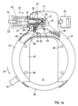
- Fig. 1a shows, in a partially cutaway front view, the basic structure of an exemplary embodiment of a frame lock.
- This frame lock is mounted, for example, on the rear fork of a bicycle (not shown in the figures). There, the frame lock enables locking of the rear spoked wheel of this bicycle to prevent unauthorized riding of the bicycle.
- the frame lock has a housing with a base section 11, to which a bearing leg 13 and a receiving leg 15 of the housing are connected.
- the bearing leg 13 and the receiving leg 15 together essentially form a horseshoe shape and enclose a locking area 17 of the frame lock. A portion of the rear wheel extends into this locking area if the frame lock is mounted on the rear fork of a bicycle, as explained.
- a locking cylinder 19 Arranged within the base section 11 is a locking cylinder 19, which is coupled to a locking bolt 21, here designed as a bar bolt.
- the locking cylinder 19 and thus the locking bolt 21 can be operated by means of a key 23.
- a substantially hollow-cylindrical block receptacle 25 is formed within the base section 11.
- the front end of the free end 71 of the block 27 bears against an ejection spring 32, which is permanently fastened, for example welded or riveted, to the front side of the block receptacle 25.
- the link chain 29 has a plurality of chain links arranged in a row (not shown), which can be surrounded by a protective sheath or hose.
- the link chain 29 has a threading element, which can be rigid or flexible, in particular, and which generally has a circumferentially closed opening through which the block 27 can be passed.
- the threading element can be designed, for example, as a ring or as a loop, as can be seen from the DE 103 58 300 A1
- the link chain 29 can again form a closed Form a chain loop, which can be placed, for example, around a stationary fastening object (e.g., lamppost), while the clamp 27 is locked to the frame lock. This can, for example, prevent the bicycle to which the frame lock is attached from being carried away without authorization.
- a clamp bolt 33 engages in the clamp receptacle 25 and there in the annular groove 31 of the clamp 27.
- the clamp bolt 33 is preloaded by a compression spring 35 along a preload direction 37.
- a locking bolt 39 designed here as a round bracket.
- one end of the locking bolt 39 protrudes into the base section 11, and the other end extends transversely through the locking area 17 so that its tip is received within the receiving leg 15.
- a handle 41 is permanently attached, for example, welded, to the locking bolt 39. The handle 41 protrudes from the bearing leg 13 through a lateral guide slot (not visible in the figures).
- a release recess 43 is formed at the end of the locking bolt 39 extending along the base section 11, specifically on the inside of the locking bolt 39.
- a coupling hook 45 of the clamp bolt 33 rests against this release recess 43.
- Adjacent to the release recess 43 with respect to a closing direction 47, the locking bolt 39 has a retention protrusion 49 that ultimately corresponds to the regular material thickness of the locking bolt 39, but is offset in height relative to the release recess 43 with respect to the pretensioning direction 37 of the clamp bolt 33.
- the transition between the release recess 43 and the adjacent retention protrusion 49 forms an inclined positive guide section 51.
- a locking groove 53 is also formed, into which the bar bolt 21 engages. Furthermore, this end is connected to a tension spring 55, which preloads the locking bolt 39 against the closing direction 47.
- the frame lock shown is also provided with stiffening surfaces 57. Furthermore, connecting rivets 59 are shown, which connect an upper and a lower housing part (not shown in detail in the figures).
- the Fig. 1a The frame lock shown generally serves to selectively block the spoked wheel located in the locking area 17, namely by the locking bolt 39 crossing the locking area 17 and thus running between two adjacent spokes of the spoked wheel.
- the locking bolt 39 is released from the Fig. 1a shown closed position, opposite to the closing direction 47, into a release position.
- the locking cylinder 19 is rotated using the key 23.
- This rotational actuation is converted - for example via an eccentric coupling - into a sliding movement of the locking bolt 21, so that the bar bolt 21 is pulled out of the locking groove 23 of the locking bolt 39.
- the tension spring 55 pulls the thus released locking bolt 39 in the direction of the receiving leg 15, so that the locking bolt 39 releases the locking area 17.
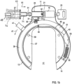
- Fig. 1b shows a completely cutaway front view of the frame lock in the thus assumed release position of the locking bolt 39. If the locking bolt 39 is subsequently to be moved back into the closed position, the locking bolt 39 is moved by means of the handle 41 against the tensile force of the tension spring 55 in the closing direction 47. In the thus assumed closed position, the locking bolt 39 is secured by the bar bolt 21 again engages in the locking groove 53. In this case, deviating from the simplified illustration according to Fig. 1a - automatic locking of the bar latch 21 must also be provided.
- the Fig. 1a and 1b The frame lock shown in the drawing secures or fixes the clamp 27 to the frame lock. This allows the bicycle to be secured, for example, to a fastening object such as a lamp post using the link chain 29.
- the clamp 27 is moved while the locking bolt 39 is in the closed position according to Fig. 1a is inserted into the clamp receptacle 25 along an insertion direction 61.
- the clamp 27, with its conical front end briefly displaces the clamp bolt 33 against the pretensioning direction 37, and the pressure of the ejection spring 32 must be overcome.
- the clamp bolt 33 snaps back into the clamp receptacle 25 due to the compressive force exerted by the compression spring 35 and thus engages the annular groove 31.
- the clamp bolt 33 is now in its closed position, and the clamp 27 is fixed within the clamp receptacle 25.
- This engagement of the clamp bolt 33 in the clamp receptacle 25 is possible because, in the closed position of the locking bolt 39, the coupling hook 25 of the clamp bolt 33 can enter the release recess 43 of the locking bolt 39.
- the coupling hook 45 is retracted along the oblique forced guide section 51 against the pretensioning direction 37 and subsequently held in the retracted position on the retention elevation 49 of the locking bolt 39.
- the clamp bolt 33 also disengages from the annular groove 31 of the clamp 27 and is is thus in its release position.
- the ejection spring 32 ensures that the clamp 27 is at least partially forced out of the clamp receptacle 25 in the opposite direction to the insertion direction 61.
- the clamp 27 can now be removed from the clamp receptacle 25.
- the clamp 27 can only be secured in the clamp receptacle 25 if the locking bolt 39 is completely closed, as in Fig. 1a This prevents the user of the frame lock from merely fixing the block 27 to the frame lock and forgetting to also close the locking bolt 39.
- the clamp 27 can be removed from the Fig. 1a and 1b
- the frame lock system shown can only be secured in the closed position of the locking bolt 39 in the clamp receptacle 25; however, the frame lock system can also be modified so that the clamp 27 can be secured in the clamp receptacle 25 both in the closed position and in the release position of the locking bolt 39, as is the case with the embodiment according to Fig. 2 the DE 102 52 080 A1 is the case, to which explicit reference is hereby made.
- the clamp 27 has a free end 71 which is designed to be received by the clamp receptacle 25 and secured therein, for which purpose the annular groove 31 serves, into which the clamp bolt 33 engages in the closed or in the release position.
- the clamp 27 forms a gripping section 73, in the region of which the clamp 27 can be grasped by a user to insert its free end 71 into the clamp receptacle 25.
- an opening 75 is formed through which the first chain link 77 of the link chain 29 extends, whereby the clamp 27 engages with the first chain link 77 and is thus secured thereto.
- the handle portion 73 of the clamp 27 is surrounded by a substantially hollow-cylindrical protective sleeve 79 made of a permanently elastic plastic material.
- the protective sleeve 79 has a circumferential annular groove 81 which receives an annular projection 83 formed along the inner circumference of the protective sleeve 79, whereby the protective sleeve 79 is positively secured to the handle portion 73 of the clamp 27.
- the protective sleeve 79 can be secured by means of a retaining ring 87, which is fitted into an annular groove 85 formed on the outer circumference of the protective sleeve 79.
- the first chain link 77 would always be held and aligned by the protective sleeve 79 in such a way that it extends essentially in axial alignment with the block 27.
- the invention provides that the protective sleeve 79 has one and preferably two slots 89, which, starting from the side facing the chain 29, second end 93 of the protective sleeve 79 in the direction of the first end 91 of the protective sleeve 79 facing the free end 71 of the block 27.
- the first chain link 77 can thus be pivoted through one of the two slots 89 and thus angled relative to the block 27 (see Fig. 3 ), so that the first chain link 77 no longer represents an obstacle protruding laterally from a two-wheeler when the clamp 27 is secured with its free end 71 in the clamp receptacle 25 of a frame lock.
- the two slots 89 extend from the second sleeve end 93 in the direction of the first sleeve end 91 up to over the opening 75 formed in the handle section 73 of the clamp 27, whereby it can be ensured that the first chain link 77 can move essentially freely relative to the clamp 27.
- the two slots 89 also have a clear width that essentially corresponds to the nominal thickness of the first chain link 77.
Landscapes
- Engineering & Computer Science (AREA)
- Mechanical Engineering (AREA)
- Lock And Its Accessories (AREA)
- Clamps And Clips (AREA)
Claims (5)
- Chaîne à maillons (29) pour sécuriser un deux-roues au moyen d'un antivol de cadre,comprenant plusieurs maillons de chaîne, la chaîne à maillons (29) présentant à une première extrémité un premier maillon de chaîne (77) qui est en prise avec un gond (27), le premier maillon de chaîne (77) passant à cet effet à travers une ouverture (75) ménagée sur une partie de préhension (73) du gond (27) détournée de l'extrémité libre (71) du gond (27) ;caractérisée en ce quela chaîne à maillons (29) présente à une deuxième extrémité, détournée de la première extrémité, un élément de passage qui est conçu de telle sorte que le gond (27) peut être passé à travers celui-ci pour former une boucle de chaîne ; et en ce queun manchon de protection (79) est fixé sur la partie de préhension (73) du gond (27), lequel entoure la partie de préhension (73) et présente une première extrémité (91) tournée vers l'extrémité libre du gond (27) et une deuxième extrémité (93) détournée de la première extrémité (91) du manchon (79), le manchon (79) présentant au moins une fente (89) qui s'étend depuis la deuxième extrémité de manchon (93) en direction de la première extrémité de manchon (91) jusque sur l'ouverture (75) ménagée dans la partie de préhension (73) du gond (27).
- Chaîne à maillons selon la revendication 1,
caractérisée en ce que
le manchon (79) présente deux fentes (89) opposées l'une à l'autre, qui s'étendent depuis la deuxième extrémité de manchon (93) en direction de la première extrémité de manchon (91). - Chaîne à maillons selon la revendication 1 et/ou 2,
caractérisée en ce que
ladite au moins une fente (89) présente une largeur libre qui correspond à l'épaisseur nominale du premier maillon de chaîne (77). - Chaîne à maillons selon l'une au moins des revendications 1 à 3,
caractérisée en ce que
le manchon de protection (79) s'étend sur toute la longueur de la partie de préhension (73) du gond (27). - Système d'antivol de cadre destiné à un deux-roues, comprenant :un antivol de cadre présentant un verrou de fermeture (39) qui est mobile entre une position de fermeture pour bloquer une roue à rayons d'un deux-roues et une position de libération pour libérer une roue à rayons ; etune chaîne à maillons (29) ;l'antivol de cadre présentant en outre un logement à gond (25) pour recevoir l'extrémité libre (71) du gond (27) ;caractérisé en ce quela chaîne à maillons (29) est conçue selon l'une au moins des revendications 1 à 4.
Applications Claiming Priority (1)
| Application Number | Priority Date | Filing Date | Title |
|---|---|---|---|
| DE102018111311.0A DE102018111311A1 (de) | 2018-05-11 | 2018-05-11 | Rahmenschlosssystem für ein Zweirad |
Publications (3)
| Publication Number | Publication Date |
|---|---|
| EP3566933A1 EP3566933A1 (fr) | 2019-11-13 |
| EP3566933B1 true EP3566933B1 (fr) | 2025-03-26 |
| EP3566933C0 EP3566933C0 (fr) | 2025-03-26 |
Family
ID=66476552
Family Applications (1)
| Application Number | Title | Priority Date | Filing Date |
|---|---|---|---|
| EP19173622.2A Active EP3566933B1 (fr) | 2018-05-11 | 2019-05-09 | Chaîne de liaison et système de verrouillage du cadre pour un véhicule à deux roues |
Country Status (2)
| Country | Link |
|---|---|
| EP (1) | EP3566933B1 (fr) |
| DE (1) | DE102018111311A1 (fr) |
Families Citing this family (7)
| Publication number | Priority date | Publication date | Assignee | Title |
|---|---|---|---|---|
| DE102021114205B4 (de) * | 2021-06-01 | 2022-12-29 | ABUS August Bremicker Söhne Kommanditgesellschaft | Rahmenschloss |
| FR3124481B1 (fr) | 2021-06-25 | 2024-03-08 | Ecox Entreprises | Ensemble d’arrimage et de recharge d’un vélo électrique, à un kit d’arrimage et de recharge, à un antivol de cadre pour vélo, à une borne de recharge et à un lien souple d’arrimage de vélo |
| US12146346B2 (en) | 2022-09-23 | 2024-11-19 | Schlage Lock Company Llc | Attack-resistant ring lock |
| US12195999B2 (en) | 2022-09-23 | 2025-01-14 | Schlage Lock Company Llc | Ring lock with relocking |
| US12252902B2 (en) | 2022-09-23 | 2025-03-18 | Schlage Lock Company Llc | Portable lock apparatus with status indicator |
| US12179869B2 (en) | 2022-09-23 | 2024-12-31 | Schlage Lock Company Llc | Portable lock apparatus |
| US20260101875A1 (en) * | 2024-10-16 | 2026-04-16 | Darryl Kimble | Pet safety collar device |
Family Cites Families (8)
| Publication number | Priority date | Publication date | Assignee | Title |
|---|---|---|---|---|
| US5899099A (en) * | 1998-06-04 | 1999-05-04 | Tsai; Cheng-Tao | Combination lock |
| DE10252080A1 (de) * | 2002-11-08 | 2004-05-27 | ABUS August Bremicker Söhne KG | Rahmenschloss |
| JP2004183299A (ja) * | 2002-12-03 | 2004-07-02 | Eiji Ishikawa | 警報機能付錠 |
| DE10358300B4 (de) * | 2003-12-12 | 2014-02-20 | ABUS August Bremicker Söhne KG | Schwenkbügel-Rahmenschloss, Verwendung eines Schwenkbügel-Rahmenschlosses und Zweirad-Sicherungssystem mit einem Schwenkbügel-Rahmenschloss und einem Sicherungsseil |
| EP1834864A1 (fr) * | 2006-03-16 | 2007-09-19 | Luma Industrias, S.A. | Serrure d'encerclement pour bicyclettes contenant des pièces blindées et des moyens pour bloquer le tenon d'un verrou à câble |
| EP3069968A1 (fr) * | 2015-03-16 | 2016-09-21 | Kipando BVBA | Verrou de bicyclette électrique traversant la roue |
| DE202016101782U1 (de) * | 2016-04-05 | 2016-04-26 | Trelock Gmbh | Rahmenschloss |
| EP3362339A4 (fr) * | 2016-10-29 | 2019-06-26 | Linka Technologies LLC | Dispositif de sécurité pour bicyclette |
-
2018
- 2018-05-11 DE DE102018111311.0A patent/DE102018111311A1/de not_active Ceased
-
2019
- 2019-05-09 EP EP19173622.2A patent/EP3566933B1/fr active Active
Also Published As
| Publication number | Publication date |
|---|---|
| DE102018111311A1 (de) | 2019-11-14 |
| EP3566933A1 (fr) | 2019-11-13 |
| EP3566933C0 (fr) | 2025-03-26 |
Similar Documents
| Publication | Publication Date | Title |
|---|---|---|
| EP3566933B1 (fr) | Chaîne de liaison et système de verrouillage du cadre pour un véhicule à deux roues | |
| EP0415355B1 (fr) | Moyens de verrouillage pour une serrure, notamment pour une serrure à câble | |
| EP3054068B1 (fr) | Serrure articulee | |
| EP3741932B1 (fr) | Verrou d'aiguille à articulation | |
| DE10319153B3 (de) | Türaußengriff, insbesondere für Fahrzeuge | |
| EP3109141B1 (fr) | Fixation | |
| DE102009030031A1 (de) | Bügelschloss | |
| DE102010008054B4 (de) | Zweirad-Schloss | |
| DE10252080A1 (de) | Rahmenschloss | |
| WO2016095890A1 (fr) | Dispositif antivol de cycle | |
| DE202014006369U1 (de) | Ringbügelschloss | |
| DE3223778C2 (fr) | ||
| EP3135574B1 (fr) | Couplage | |
| EP2400089B1 (fr) | Verrou à boucle | |
| EP0476260B1 (fr) | Dispositif de fixation mot clef : Fixation d'un câble sur un cadre de bicyclette | |
| DE202015106650U1 (de) | Schnellspann-Steckachse für Zweiräder | |
| EP2993090B2 (fr) | Verrouillage de volant de direction | |
| EP1416110B1 (fr) | Serrure d'encerclement pour deux roues | |
| DE69111144T2 (de) | Diebstahlsicherung für Kraftfahrzeugräder. | |
| EP2266869A2 (fr) | Serrure pour disques de frein dotée d'un boulon de fermeture oblique | |
| WO2018114400A1 (fr) | Cadenas | |
| EP1101634B1 (fr) | Dispositif de remorquage et son procédé de fabrication | |
| DE3205133C2 (fr) | ||
| EP3053782B1 (fr) | Dispositif de liaison rapide destine a relier une protection anti-encastrement a un vehicule automobile et vehicule automobile comprenant un tel dispositif de liaison rapide | |
| DE3313694A1 (de) | Vorrichtung zur befestigung eines rades an einem fahrzeug |
Legal Events
| Date | Code | Title | Description |
|---|---|---|---|
| PUAI | Public reference made under article 153(3) epc to a published international application that has entered the european phase |
Free format text: ORIGINAL CODE: 0009012 |
|
| STAA | Information on the status of an ep patent application or granted ep patent |
Free format text: STATUS: THE APPLICATION HAS BEEN PUBLISHED |
|
| AK | Designated contracting states |
Kind code of ref document: A1 Designated state(s): AL AT BE BG CH CY CZ DE DK EE ES FI FR GB GR HR HU IE IS IT LI LT LU LV MC MK MT NL NO PL PT RO RS SE SI SK SM TR |
|
| AX | Request for extension of the european patent |
Extension state: BA ME |
|
| STAA | Information on the status of an ep patent application or granted ep patent |
Free format text: STATUS: REQUEST FOR EXAMINATION WAS MADE |
|
| 17P | Request for examination filed |
Effective date: 20200331 |
|
| RBV | Designated contracting states (corrected) |
Designated state(s): AL AT BE BG CH CY CZ DE DK EE ES FI FR GB GR HR HU IE IS IT LI LT LU LV MC MK MT NL NO PL PT RO RS SE SI SK SM TR |
|
| STAA | Information on the status of an ep patent application or granted ep patent |
Free format text: STATUS: EXAMINATION IS IN PROGRESS |
|
| 17Q | First examination report despatched |
Effective date: 20220530 |
|
| GRAP | Despatch of communication of intention to grant a patent |
Free format text: ORIGINAL CODE: EPIDOSNIGR1 |
|
| STAA | Information on the status of an ep patent application or granted ep patent |
Free format text: STATUS: GRANT OF PATENT IS INTENDED |
|
| RIC1 | Information provided on ipc code assigned before grant |
Ipc: E05B 71/00 20060101ALI20241129BHEP Ipc: B62H 5/14 20060101ALI20241129BHEP Ipc: B62H 5/00 20060101AFI20241129BHEP |
|
| INTG | Intention to grant announced |
Effective date: 20241213 |
|
| GRAS | Grant fee paid |
Free format text: ORIGINAL CODE: EPIDOSNIGR3 |
|
| GRAA | (expected) grant |
Free format text: ORIGINAL CODE: 0009210 |
|
| STAA | Information on the status of an ep patent application or granted ep patent |
Free format text: STATUS: THE PATENT HAS BEEN GRANTED |
|
| AK | Designated contracting states |
Kind code of ref document: B1 Designated state(s): AL AT BE BG CH CY CZ DE DK EE ES FI FR GB GR HR HU IE IS IT LI LT LU LV MC MK MT NL NO PL PT RO RS SE SI SK SM TR |
|
| REG | Reference to a national code |
Ref country code: GB Ref legal event code: FG4D Free format text: NOT ENGLISH |
|
| REG | Reference to a national code |
Ref country code: CH Ref legal event code: EP |
|
| REG | Reference to a national code |
Ref country code: DE Ref legal event code: R096 Ref document number: 502019013095 Country of ref document: DE |
|
| REG | Reference to a national code |
Ref country code: IE Ref legal event code: FG4D Free format text: LANGUAGE OF EP DOCUMENT: GERMAN |
|
| U01 | Request for unitary effect filed |
Effective date: 20250326 |
|
| U07 | Unitary effect registered |
Designated state(s): AT BE BG DE DK EE FI FR IT LT LU LV MT NL PT RO SE SI Effective date: 20250402 |
|
| U20 | Renewal fee for the european patent with unitary effect paid |
Year of fee payment: 7 Effective date: 20250527 |
|
| PG25 | Lapsed in a contracting state [announced via postgrant information from national office to epo] |
Ref country code: RS Free format text: LAPSE BECAUSE OF FAILURE TO SUBMIT A TRANSLATION OF THE DESCRIPTION OR TO PAY THE FEE WITHIN THE PRESCRIBED TIME-LIMIT Effective date: 20250626 |
|
| PG25 | Lapsed in a contracting state [announced via postgrant information from national office to epo] |
Ref country code: NO Free format text: LAPSE BECAUSE OF FAILURE TO SUBMIT A TRANSLATION OF THE DESCRIPTION OR TO PAY THE FEE WITHIN THE PRESCRIBED TIME-LIMIT Effective date: 20250626 |
|
| PG25 | Lapsed in a contracting state [announced via postgrant information from national office to epo] |
Ref country code: HR Free format text: LAPSE BECAUSE OF FAILURE TO SUBMIT A TRANSLATION OF THE DESCRIPTION OR TO PAY THE FEE WITHIN THE PRESCRIBED TIME-LIMIT Effective date: 20250326 |
|
| PG25 | Lapsed in a contracting state [announced via postgrant information from national office to epo] |
Ref country code: SM Free format text: LAPSE BECAUSE OF FAILURE TO SUBMIT A TRANSLATION OF THE DESCRIPTION OR TO PAY THE FEE WITHIN THE PRESCRIBED TIME-LIMIT Effective date: 20250326 |
|
| PG25 | Lapsed in a contracting state [announced via postgrant information from national office to epo] |
Ref country code: ES Free format text: LAPSE BECAUSE OF FAILURE TO SUBMIT A TRANSLATION OF THE DESCRIPTION OR TO PAY THE FEE WITHIN THE PRESCRIBED TIME-LIMIT Effective date: 20250326 |
|
| PG25 | Lapsed in a contracting state [announced via postgrant information from national office to epo] |
Ref country code: PL Free format text: LAPSE BECAUSE OF FAILURE TO SUBMIT A TRANSLATION OF THE DESCRIPTION OR TO PAY THE FEE WITHIN THE PRESCRIBED TIME-LIMIT Effective date: 20250326 |
|
| PG25 | Lapsed in a contracting state [announced via postgrant information from national office to epo] |
Ref country code: SK Free format text: LAPSE BECAUSE OF FAILURE TO SUBMIT A TRANSLATION OF THE DESCRIPTION OR TO PAY THE FEE WITHIN THE PRESCRIBED TIME-LIMIT Effective date: 20250326 |
|
| PG25 | Lapsed in a contracting state [announced via postgrant information from national office to epo] |
Ref country code: IS Free format text: LAPSE BECAUSE OF FAILURE TO SUBMIT A TRANSLATION OF THE DESCRIPTION OR TO PAY THE FEE WITHIN THE PRESCRIBED TIME-LIMIT Effective date: 20250726 |
|
| REG | Reference to a national code |
Ref country code: CH Ref legal event code: H13 Free format text: ST27 STATUS EVENT CODE: U-0-0-H10-H13 (AS PROVIDED BY THE NATIONAL OFFICE) Effective date: 20251223 |
|
| PG25 | Lapsed in a contracting state [announced via postgrant information from national office to epo] |
Ref country code: CH Free format text: LAPSE BECAUSE OF NON-PAYMENT OF DUE FEES Effective date: 20250531 |
|
| PG25 | Lapsed in a contracting state [announced via postgrant information from national office to epo] |
Ref country code: CZ Free format text: LAPSE BECAUSE OF FAILURE TO SUBMIT A TRANSLATION OF THE DESCRIPTION OR TO PAY THE FEE WITHIN THE PRESCRIBED TIME-LIMIT Effective date: 20250326 |
|
| PG25 | Lapsed in a contracting state [announced via postgrant information from national office to epo] |
Ref country code: MC Free format text: LAPSE BECAUSE OF FAILURE TO SUBMIT A TRANSLATION OF THE DESCRIPTION OR TO PAY THE FEE WITHIN THE PRESCRIBED TIME-LIMIT Effective date: 20250326 |
|
| PLBE | No opposition filed within time limit |
Free format text: ORIGINAL CODE: 0009261 |
|
| STAA | Information on the status of an ep patent application or granted ep patent |
Free format text: STATUS: NO OPPOSITION FILED WITHIN TIME LIMIT |
|
| REG | Reference to a national code |
Ref country code: CH Ref legal event code: L10 Free format text: ST27 STATUS EVENT CODE: U-0-0-L10-L00 (AS PROVIDED BY THE NATIONAL OFFICE) Effective date: 20260211 |
|
| GBPC | Gb: european patent ceased through non-payment of renewal fee |
Effective date: 20250626 |
|
| 26N | No opposition filed |
Effective date: 20260105 |
|
| PG25 | Lapsed in a contracting state [announced via postgrant information from national office to epo] |
Ref country code: GB Free format text: LAPSE BECAUSE OF NON-PAYMENT OF DUE FEES Effective date: 20250626 |
|
| PG25 | Lapsed in a contracting state [announced via postgrant information from national office to epo] |
Ref country code: IE Free format text: LAPSE BECAUSE OF NON-PAYMENT OF DUE FEES Effective date: 20250509 |