EP3567256B1 - Module de surveillance et procédé permettant d'identifier un scénario de fonctionnement dans une station de pompage des eaux usées - Google Patents
Module de surveillance et procédé permettant d'identifier un scénario de fonctionnement dans une station de pompage des eaux usées Download PDFInfo
- Publication number
- EP3567256B1 EP3567256B1 EP18171929.5A EP18171929A EP3567256B1 EP 3567256 B1 EP3567256 B1 EP 3567256B1 EP 18171929 A EP18171929 A EP 18171929A EP 3567256 B1 EP3567256 B1 EP 3567256B1
- Authority
- EP
- European Patent Office
- Prior art keywords
- pipe
- wastewater
- pump
- pumps
- criterion
- Prior art date
- Legal status (The legal status is an assumption and is not a legal conclusion. Google has not performed a legal analysis and makes no representation as to the accuracy of the status listed.)
- Active
Links
Images



Classifications
-
- F—MECHANICAL ENGINEERING; LIGHTING; HEATING; WEAPONS; BLASTING
- F04—POSITIVE - DISPLACEMENT MACHINES FOR LIQUIDS; PUMPS FOR LIQUIDS OR ELASTIC FLUIDS
- F04D—NON-POSITIVE-DISPLACEMENT PUMPS
- F04D15/00—Control, e.g. regulation, of pumps, pumping installations or systems
- F04D15/0088—Testing machines
-
- F—MECHANICAL ENGINEERING; LIGHTING; HEATING; WEAPONS; BLASTING
- F04—POSITIVE - DISPLACEMENT MACHINES FOR LIQUIDS; PUMPS FOR LIQUIDS OR ELASTIC FLUIDS
- F04D—NON-POSITIVE-DISPLACEMENT PUMPS
- F04D13/00—Pumping installations or systems
- F04D13/02—Units comprising pumps and their driving means
- F04D13/06—Units comprising pumps and their driving means the pump being electrically driven
-
- F—MECHANICAL ENGINEERING; LIGHTING; HEATING; WEAPONS; BLASTING
- F04—POSITIVE - DISPLACEMENT MACHINES FOR LIQUIDS; PUMPS FOR LIQUIDS OR ELASTIC FLUIDS
- F04D—NON-POSITIVE-DISPLACEMENT PUMPS
- F04D15/00—Control, e.g. regulation, of pumps, pumping installations or systems
- F04D15/02—Stopping of pumps, or operating valves, on occurrence of unwanted conditions
- F04D15/0209—Stopping of pumps, or operating valves, on occurrence of unwanted conditions responsive to a condition of the working fluid
- F04D15/0218—Stopping of pumps, or operating valves, on occurrence of unwanted conditions responsive to a condition of the working fluid the condition being a liquid level or a lack of liquid supply
- F04D15/0236—Lack of liquid level being detected by analysing the parameters of the electric drive, e.g. current or power consumption
-
- F—MECHANICAL ENGINEERING; LIGHTING; HEATING; WEAPONS; BLASTING
- F04—POSITIVE - DISPLACEMENT MACHINES FOR LIQUIDS; PUMPS FOR LIQUIDS OR ELASTIC FLUIDS
- F04D—NON-POSITIVE-DISPLACEMENT PUMPS
- F04D15/00—Control, e.g. regulation, of pumps, pumping installations or systems
- F04D15/02—Stopping of pumps, or operating valves, on occurrence of unwanted conditions
- F04D15/0245—Stopping of pumps, or operating valves, on occurrence of unwanted conditions responsive to a condition of the pump
-
- F—MECHANICAL ENGINEERING; LIGHTING; HEATING; WEAPONS; BLASTING
- F04—POSITIVE - DISPLACEMENT MACHINES FOR LIQUIDS; PUMPS FOR LIQUIDS OR ELASTIC FLUIDS
- F04D—NON-POSITIVE-DISPLACEMENT PUMPS
- F04D15/00—Control, e.g. regulation, of pumps, pumping installations or systems
- F04D15/02—Stopping of pumps, or operating valves, on occurrence of unwanted conditions
- F04D15/029—Stopping of pumps, or operating valves, on occurrence of unwanted conditions for pumps operating in parallel
-
- F—MECHANICAL ENGINEERING; LIGHTING; HEATING; WEAPONS; BLASTING
- F04—POSITIVE - DISPLACEMENT MACHINES FOR LIQUIDS; PUMPS FOR LIQUIDS OR ELASTIC FLUIDS
- F04D—NON-POSITIVE-DISPLACEMENT PUMPS
- F04D13/00—Pumping installations or systems
- F04D13/12—Combinations of two or more pumps
-
- F—MECHANICAL ENGINEERING; LIGHTING; HEATING; WEAPONS; BLASTING
- F05—INDEXING SCHEMES RELATING TO ENGINES OR PUMPS IN VARIOUS SUBCLASSES OF CLASSES F01-F04
- F05D—INDEXING SCHEME FOR ASPECTS RELATING TO NON-POSITIVE-DISPLACEMENT MACHINES OR ENGINES, GAS-TURBINES OR JET-PROPULSION PLANTS
- F05D2260/00—Function
- F05D2260/80—Diagnostics
-
- F—MECHANICAL ENGINEERING; LIGHTING; HEATING; WEAPONS; BLASTING
- F05—INDEXING SCHEMES RELATING TO ENGINES OR PUMPS IN VARIOUS SUBCLASSES OF CLASSES F01-F04
- F05D—INDEXING SCHEME FOR ASPECTS RELATING TO NON-POSITIVE-DISPLACEMENT MACHINES OR ENGINES, GAS-TURBINES OR JET-PROPULSION PLANTS
- F05D2270/00—Control
- F05D2270/30—Control parameters, e.g. input parameters
- F05D2270/301—Pressure
- F05D2270/3013—Outlet pressure
-
- F—MECHANICAL ENGINEERING; LIGHTING; HEATING; WEAPONS; BLASTING
- F05—INDEXING SCHEMES RELATING TO ENGINES OR PUMPS IN VARIOUS SUBCLASSES OF CLASSES F01-F04
- F05D—INDEXING SCHEME FOR ASPECTS RELATING TO NON-POSITIVE-DISPLACEMENT MACHINES OR ENGINES, GAS-TURBINES OR JET-PROPULSION PLANTS
- F05D2270/00—Control
- F05D2270/30—Control parameters, e.g. input parameters
- F05D2270/306—Mass flow
- F05D2270/3061—Mass flow of the working fluid
-
- F—MECHANICAL ENGINEERING; LIGHTING; HEATING; WEAPONS; BLASTING
- F05—INDEXING SCHEMES RELATING TO ENGINES OR PUMPS IN VARIOUS SUBCLASSES OF CLASSES F01-F04
- F05D—INDEXING SCHEME FOR ASPECTS RELATING TO NON-POSITIVE-DISPLACEMENT MACHINES OR ENGINES, GAS-TURBINES OR JET-PROPULSION PLANTS
- F05D2270/00—Control
- F05D2270/30—Control parameters, e.g. input parameters
- F05D2270/335—Output power or torque
Definitions
- Sewage or wastewater collection systems for wastewater treatment plants typically comprise one or more wastewater pits, wells or sumps for temporarily collecting and buffering wastewater.
- wastewater flows into such pits passively under gravity flow and/or actively driven through a force main.
- One, two or more pumps are usually installed in or at each pit to pump wastewater out of the pit. If the inflow of wastewater is larger than the outflow for a certain period of time, the wastewater pit or sump will eventually overflow. Such overflows should be prevented as much as possible in order to avoid environmental impact. Therefore, any pump fault or clogging, pipe clogging, leakage or other type of faulty operating scenario should be identified as quickly as possible for maintenance staff to take according action, like cleaning, repairing or replacing as quickly as possible.
- US 8,594,851 B1 describes a wastewater treatment system and a method for reducing energy used in operation of a wastewater treatment facility.
- US 2012/0101788 A1 describes a method for determining faults during operations of a single pump unit.
- US 2010/0300220 A1 describes a method that serves for monitoring a single pump.
- the paper "Model based fault diagnosis in a centrifugal pump application using structural analysis” by Kallesoe et al., published in "Proceedings of the 2004 IEEE International Conference on Control Applications", Taipei, Taiwan, September 2-4, 2004, vol. 2, pages 1229-1235 describes a model based approach for fault detection and isolation in a single centrifugal pump.
- US 4 945 491 A describes a multi-pump system in which the wire-to-water efficiency is monitored.
- the present invention provides a wastewater pumping station with two or more pumps as defined in claim 1 and a method for identifying an operating scenario in the wastewater pumping station as defined in claim 13 with more specific and more reliable information.
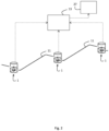
- a wastewater pumping station comprising two or more pumps arranged for pumping wastewater out of a wastewater pit into a pipe and a monitoring module for identifying an operating scenario in the wastewater pumping station is provided.
- the group of operating scenarios may be predefined in a selection matrix unambiguously associating each operating scenario with a unique combination of the at least one first criterion, the at least one second criterion, and the at least one third criterion.
- three different operating scenarios may be identified based on the combination of the two criteria as follows: First criterion Second criterion Scenario 1; pipe is clogged pump variable rising pipe parameter negative or non-zero Scenario 2; pump is clogged pump variable rising pipe parameter positive or zero Scenario 3; pump connection is leaking pump variable falling pipe parameter negative or non-zero
- a first criterion for each pump is used to distinguish between operating scenarios in which a specific pump is clogged or pump connection is leaking, for example.
- five different operating scenarios may be identified based on the combination of the two criteria as follows: First criterion for pump 1 First criterion for pump 2 Second criterion Scenario 1; pipe is clogged pump 1 variable rising pump 2 variable rising pipe parameter negative or non-zero Scenario 2; pump 1 is clogged pump 1 variable rising pump 2 variable not rising pipe parameter positive or zero Scenario 3; pump 2 is clogged pump 1 variable not rising pump 2 variable rising pipe parameter positive or zero Scenario 4; pump 1 connection is leaking pump 1 variable falling pump 2 variable not falling pipe parameter negative or non-zero Scenario 5; pump 2 connection is leaking pump 1 variable not falling pump 2 variable falling pipe parameter negative or non-zero
- the current specific energy consumption E sp (t) may be monitored as the at least one load-dependent pump variable as an alternative to the averaged specific energy consumption E sp as defined above. If the current specific energy consumption E sp (t) fluctuates too much to the at least one first criterion on it, a low-pass filtering may be applied as explained later herein. Even in case of a specific energy consumption E sp that is averaged for each pump cycle, it can fluctuate between the pump cycles so much that a low-pass filtering may be advantageous.
- the outflow q of wastewater through the pump(s) may be estimated by q ⁇ s ⁇ 0 ⁇ + s ⁇ 1 ⁇ ⁇ p + s ⁇ 2 ⁇ 2 P + s ⁇ 3 ⁇ , wherein s is the number of running pumps, ⁇ is the pump speed (e. g.
- the monitoring module may be signal connected wirelessly or via a cable with a pressure sensor, which is located at or downstream of the pump(s), to receive a signal indicative of the pressure differential ⁇ p. So, optionally, the monitoring module may be configured to receive a measured pressure p m at or downstream of an outlet of the at least pump. Alternatively or in addition, the monitoring module may be configured to receive a measured flow q m through the pipe or to process an estimated wastewater flow q e through the pump.
- the "scenario signature" may depend on whether a flow q through the pipe is measured or a flow q through the pump(s) is estimated. For instance, a leak in a pump connection or in a non-return valve may result in a rising specific energy consumption E sp when the flow q through the pipe is measured. However, if a flow q through the pump(s) is estimated, the specific energy consumption E sp may turn out to be falling. Therefore, the monitoring module may be configured to apply one of at least two predefined selection matrices dependent on whether a flow q through the pipe is measured or a flow q through the pump(s) is estimated. Each of the at least two selection matrices unambiguously associate each operating scenario with a unique combination of the at least one first criterion, the at least one second criterion, and the at least one third criterion.
- the zero-flow offset parameter B may be a second one of at least two model-based pipe parameters, wherein the pipe clogging parameter A may be a first one of the at least two model-based pipe parameters.
- the residual r may be considered as a pipe model testing parameter. If the residual r deviates from zero by more than a certain threshold, e.g.
- one of the at least one second criterion may be fulfilled, otherwise not.
- Such a fulfilled second criterion may mean a "model mismatch", indicating a pipe clogging, whereas a non-fulfilled second criterion may mean a "model match", indicating a pump problem rather than a pipe clogging.
- a leak in a pump connection or in a non-return valve may show a model mismatch when the flow through the pump(s) is estimated, but a model match if a flow q through the pipe is measured.
- the monitoring module may be configured to sequentially process a multitude of samples of the at least one load-dependent pump variable, wherein the at least one first criterion is based on whether a cumulative sum of deviations between the actual sample and an average of past samples of the at least one load-dependent pump variable exceeds a predetermined maximum or falls below a predetermined minimum.
- the average specific energy consumption E sp may be a predefined value or a value statistically determined over several previous pump cycles during normal faultless operation. For instance, it may be useful to identify non-faulty operating scenarios to statistically determine an average specific energy consumption E sp .
- a first one of the at least one first criterion based on the specific energy consumption E sp may be whether the decision variable S up is above or below an alarm threshold indicating that the specific energy consumption E sp is rising.
- a second one of the at least one first criterion based on the specific energy consumption E sp may be whether the decision variable S down is above or below an alarm threshold indicating that the specific energy consumption E sp is falling.
- the specific energy consumption E sp would appear as falling if the flow through the pump is estimated. If the flow through pipe is measured, the specific energy consumption E sp would be rising in case of pipe clogging, pump fault/clogging and leakage of a pump connection or a non-return valve. In case of a wastewater pumping station with m ⁇ 2 pumps, there may be two first criteria per pump, i. e. 2 times m first criteria to identify the operating scenario.
- a similar low-pass filtering may be applied to the at least one model-based pipe parameter before selecting an operating scenario dependent on the at least one second criterion.
- the monitoring module may be configured to sequentially process a multitude of samples of the at least one model-based pipe parameter, wherein the at least one second criterion is based on whether a cumulative sum of deviations between the actual sample and an average of past samples of the at least one model-based pipe parameter exceeds a predetermined maximum or falls below a predetermined minimum.
- Kalman filters may be applied to calculate the mean and variance of the pipe clogging parameter.
- the monitoring module is configured to process a first of at least two model-based pipe parameters and a zero-flow offset parameter as a second of the at least two model-based pipe parameters, wherein the negative-flow parameter is indicative of how the wastewater flows through the pipe and/or the at least one pump when the at least one pump is stopped, wherein the monitoring module may be configured to identify an operating scenario in the wastewater pumping station by selecting an operating scenario from a group of predefined operating scenarios further dependent on at least one third criterion that is based on the negative-flow parameter.
- the negative-flow parameter may be a leakage flow through one of the non-return valves or a pump connection, for instance, which will gradually lead to a pressure decay when the at least one pump is stopped.
- D ⁇ - q
- q the leakage flow.
- hypothesis H 0 cannot be rejected, there is probably a leak in the non-return-valve. If the decision variable y is above a threshold value, for instance 0.1, the hypothesis H 0 may be rejected.
- the threshold value for this third criterion may be adjusted to an acceptable compromise between the sensitivity for a leakage and a false alarm rate.
- a method for identifying an operating scenario in a wastewater pumping station with two or more pumps arranged for pumping wastewater out of a wastewater pit into a pipe.
- the group of operating scenarios may be predefined in a selection matrix unambiguously associating each operating scenario with a unique combination of the at least one first criterion, the at least one second criterion, and the at least one third criterion.
- the at least one load-dependent pump variable may be a specific energy consumption E sp of the at least one pump.
- one of the at least one second criterion may be fulfilled, otherwise not.
- Such a fulfilled second criterion may mean a "model mismatch", whereas a non-fulfilled second criterion may mean a "model match”.
- a similar low-pass filtering as described above for the specific energy consumption E sp may be applied to the residual r before selecting an operating scenario dependent on the at least one second criterion.
Landscapes
- Engineering & Computer Science (AREA)
- Mechanical Engineering (AREA)
- General Engineering & Computer Science (AREA)
- Control Of Positive-Displacement Pumps (AREA)
- Control Of Non-Positive-Displacement Pumps (AREA)
- Sewage (AREA)
- Separation Using Semi-Permeable Membranes (AREA)
Claims (24)
- Station de pompage des eaux usées comprenant :- deux pompes ou plus (9a, 9b) agencées pour pomper les eaux usées hors d'une fosse à eaux usées (1) jusque dans un conduit (11), et- un module de surveillance (13) pour identifier un scénario de fonctionnement dans la station de pompage des eaux usées,caractérisée en ce que le module de surveillance (13) est configuré pour traiter au moins une variable de pompe dépendante de la charge pour chaque pompe en fonctionnement des pompes (9a, 9b) indiquant comment la pompe en fonctionnement (9a, 9b) respective fonctionne, pour traiter un premier d'au moins deux paramètres de conduit basés sur modèle indiquant comment les eaux usées circulent à travers le conduit (11) et/ou les pompes (9a, 9b), et pour traiter un paramètre de débit négatif en tant que le second des au moins deux paramètres de conduit basés sur modèle, dans laquelle le paramètre de débit négatif indique comment les eaux usées circulent à travers le conduit et/ou la ou les pompe(s) qui ne sont pas en fonctionnement des pompes (9a, 9b) lorsqu'au moins une des pompes (9a, 9b) est arrêtée,dans laquelle le module de surveillance est configuré pour identifier un scénario de fonctionnement dans la station de pompage des eaux usées en sélectionnant un scénario de fonctionnement à partir d'un groupe de scénarios de fonctionnement prédéfinis dépendants d'au moins un premier critère pour chaque pompe en fonctionnement des pompes (9a, 9b) qui est basé sur l'au moins une variable de pompe dépendante de la charge, d'au moins un deuxième critère qui est basé sur au moins le premier des au moins deux paramètres de conduit basés sur modèle et d'au moins un troisième critère qui est basé sur le paramètre de débit négatif.
- Station de pompage des eaux usées selon la revendication 1, dans laquelle le groupe scénarios de fonctionnement est prédéfini dans une matrice de sélection associant de manière non ambiguë chaque scénario de fonctionnement à une combinaison unique de l'au moins un premier critère, de l'au moins un deuxième critère et de l'au moins un troisième critère.
- Station de pompage des eaux usées selon la revendication 1 ou 2, dans laquelle l'au moins une variable de pompe dépendante de la charge comprend une consommation d'énergie spécifique Esp de la pompe en fonctionnement (9a, 9b) respective.
- Station de pompage des eaux usées selon la revendication 3, dans laquelle la consommation d'énergie spécifique Esp de la pompe en fonctionnement (9a, 9b) respective est définie par Esp=E/V, dans laquelle E est une énergie moyenne consommée par la pompe en fonctionnement respective pendant une période de temps définie et V est le volume d'eaux usées pompées pendant ladite période de temps définie par la pompe en fonctionnement respective.
- Station de pompage des eaux usées selon la revendication 3, dans laquelle la consommation d'énergie spécifique Esp de la pompe en fonctionnement respective est définie par Esp=P/q, dans laquelle P est une consommation de courant de la pompe en fonctionnement respective et q est un débit d'eaux usées pompé par la pompe en fonctionnement respective.
- Station de pompage des eaux usées selon l'une quelconque des revendications précédentes, dans laquelle le premier des au moins deux paramètres de conduit basés sur modèle est un paramètre A d'engorgement de conduit dans un polynôme de modèle de conduit p=Aq2+B, dans laquelle p est une pression à une sortie ou en aval d'une sortie d'au moins une des pompes (9a, 9b), q est un débit d'eaux usées à travers le conduit (11) et/ou les pompes (9a, 9b), et B est un paramètre de décalage de débit nul.
- Station de pompage des eaux usées selon l'une quelconque des revendications précédentes, dans laquelle le premier des deux paramètres de conduit basés sur modèle est un résidu r=pm-pe=pm-Aq2-B entre une pression pm mesurée à une sortie ou en aval d'une sortie d'au moins une des pompes (9a, 9b) et une pression pe estimée selon un polynôme de modèle de conduit pe=Aq2+B, dans lequel A est un paramètre d'engorgement de conduit, q est un débit d'eaux usées à travers le conduit (11) et/ou les pompes (9a, 9b) et B est un paramètre de décalage de débit nul.
- Station de pompage des eaux usées selon l'une quelconque des revendications précédentes, dans laquelle le module de surveillance (13) est configuré pour recevoir une pression pm mesurée à une sortie ou en aval d'une sortie d'au moins une des pompes (9a, 9b).
- Station de pompage des eaux usées selon l'une quelconque des revendications précédentes, dans laquelle le module de surveillance (13) est configuré pour recevoir un débit qm mesuré à travers le conduit (11) ou pour traiter un débit d'eaux usées estimé qe à travers les pompes (9a, 9b).
- Station de pompage des eaux usées selon l'une quelconque des revendications précédentes, dans laquelle le module de surveillance (13) est configuré pour appliquer un filtrage passe-bas à l'au moins une variable de pompe dépendante de la charge et/ou au premier des au moins deux paramètres de conduit basés sur modèle avant de sélectionner un scénario de fonctionnement en fonction de l'au moins un premier critère, de l'au moins un deuxième critère et de l'au moins un troisième critère.
- Station de pompage des eaux usées selon l'une quelconque des revendications précédentes, dans laquelle le module de surveillance (13) est configuré pour traiter de manière séquentielle une multitude d'échantillons de l'au moins une variable de pompe dépendante de la charge, dans lequel l'au moins un premier critère est basé sur si une somme cumulative d'écarts entre l'échantillon actuel et une moyenne d'échantillons passés de l'au moins une variable de pompe dépendante de la charge dépasse un maximum prédéterminé ou tombe en-dessous d'un minimum prédéterminé.
- Station de pompage des eaux usées selon l'une quelconque des revendications précédentes, dans laquelle le module de surveillance (13) est configuré pour traiter de manière séquentielle une multitude d'échantillons du premier des au moins deux paramètres de conduit basés sur modèle, dans lequel l'au moins un deuxième critère est basé sur si une somme cumulative d'écarts entre l'échantillon actuel et une moyenne d'échantillons passés du premier des au moins deux paramètres de conduit basés sur modèle dépasse un maximum prédéterminé ou tombe en-dessous d'un minimum prédéterminé.
- Procédé d'identification d'un scénario de fonctionnement dans une station de pompage des eaux usées comprenant deux pompes ou plus (9a, 9b) agencées pour pomper les eaux usées hors d'une fosse à eaux usées (1) jusque dans un conduit (11), dans lequel le procédé est caractérisé en ce qu'il comprend :- de traiter au moins une variable de pompe dépendante de la charge pour chaque pompe en fonctionnement des pompes (9a, 9b) indiquant comment la pompe en fonctionnement (9a, 9b) respective fonctionne,- de traiter un premier d'au moins deux paramètres de conduit basés sur modèle indiquant comment les eaux usées circulent à travers le conduit (11) et/ou les pompes (9a, 9b), et- de traiter un paramètre de débit négatif en tant qu'un second des au moins deux paramètres de conduit basés sur modèle, dans lequel le paramètre de débit négatif indique comment les eaux usées circulent à travers le conduit et/ou la ou les pompes qui ne sont pas en fonctionnement des pompes (9a, 9b) lorsqu'au moins une des pompes (9a, 9b) est arrêtée, et- de sélectionner un scénario de fonctionnement à partir d'un groupe de scénarios de fonctionnement prédéfinis dépendants d'au moins un premier critère qui est basé sur l'au moins une variable de pompe dépendante de la charge, d'au moins un deuxième critère qui est basé sur au moins le premier des au moins deux paramètres de conduit basés sur modèle et d'au moins un troisième critère qui est basé sur le paramètre de débit négatif.
- Procédé selon la revendication 13, dans lequel le groupe de scénarios de fonctionnement est prédéfini dans une matrice de sélection associant de manière non ambiguë chaque scénario de fonctionnement à une combinaison unique de l'au moins un premier critère et de l'au moins un deuxième critère.
- Procédé selon la revendication 13 ou 14, dans lequel l'au moins une variable de pompe dépendante de la charge comprend une consommation d'énergie spécifique Esp de la pompe en fonctionnement (9a, 9b) respective.
- Procédé selon la revendication 15, dans lequel la consommation d'énergie spécifique Esp de la pompe en fonctionnement (9a, 9b) respective est définie par Esp=E/V, dans laquelle E est une énergie moyenne pendant une période de temps définie et V est le volume d'eaux usées pompées pendant ladite période de temps définie par la pompe en fonctionnement respective (9a, 9b).
- Procédé selon la revendication 15, dans lequel la consommation d'énergie spécifique Esp de la pompe en fonctionnement (9a, 9b) respective est définie par Es,=P/q, dans laquelle P est une consommation de courant et q est un débit d'eaux usées pompé par la pompe en fonctionnement respective (9a, 9b).
- Procédé selon l'une quelconque des revendications 13 à 17, dans lequel le premier des au moins deux paramètres de conduit basés sur modèle est un paramètre A d'engorgement de conduit dans un polynôme de modèle de conduit p=Aq2+B, dans lequel p est une pression à une sortie ou en aval d'une sortie d'au moins une des pompes (9a, 9b), q est le débit d'eaux usées à travers le conduit (11) et/ou les pompes (9a, 9b), et B est un paramètre de décalage de débit nul.
- Procédé selon l'une quelconque des revendications 13 à 18, dans lequel le premier des deux paramètres de conduit basés sur modèle est un résidu r=pm-pe=pm-Aq2-B entre une pression pm mesurée à une sortie ou en aval d'une sortie d'au moins une des pompes (9a, 9b) et une pression pe estimée selon un polynôme de modèle de conduit pe=Aq2+B, dans lequel A est un paramètre d'engorgement de conduit, q est le débit d'eaux usées à travers le conduit (11) et/ou les pompes (9a, 9b) et B est un paramètre de décalage de débit nul.
- Procédé selon l'une quelconque des revendications 13 à 19, comprenant en outre de recevoir une pression pm mesurée à une sortie ou en aval d'une sortie d'au moins une des pompes (9a, 9b).
- Procédé selon l'une quelconque des revendications 13 à 20, comprenant en outre de recevoir un débit qm mesuré à travers le conduit ou pour traiter un débit d'eaux usées estimé qe à travers les pompes (9a, 9b).
- Procédé selon l'une quelconque des revendications 13 à 21, comprenant en outre d'appliquer un filtrage passe-bas à l'au moins une variable de pompe dépendante de la charge et/ou au premier des au moins deux paramètres de conduit basés sur modèle avant de sélectionner un scénario de fonctionnement en fonction de l'au moins un premier critère, de l'au moins un deuxième critère et de l'au moins un troisième critère.
- Procédé selon l'une quelconque des revendications 13 à 21, comprenant en outre de traiter de manière séquentielle une multitude d'échantillons de l'au moins une variable de pompe dépendante de la charge, dans lequel l'au moins un premier critère est basé sur si une somme cumulative d'écarts entre l'échantillon actuel et une moyenne d'échantillons passés de l'au moins une variable de pompe dépendante de la charge dépasse un maximum prédéterminé ou tombe en-dessous d'un minimum prédéterminé.
- Procédé selon l'une quelconque des revendications 13 à 22, comprenant en outre de traiter de manière séquentielle une multitude d'échantillons du premier des au moins deux paramètres de conduit basés sur modèle, dans lequel l'au moins un deuxième critère est basé sur si une somme cumulative d'écarts entre l'échantillon actuel et une moyenne d'échantillons passés du premier des au moins deux paramètres de conduit basés sur modèle dépasse un maximum prédéterminé ou tombe en-dessous d'un minimum prédéterminé.
Priority Applications (6)
| Application Number | Priority Date | Filing Date | Title |
|---|---|---|---|
| EP18171929.5A EP3567256B1 (fr) | 2018-05-11 | 2018-05-11 | Module de surveillance et procédé permettant d'identifier un scénario de fonctionnement dans une station de pompage des eaux usées |
| ES18171929T ES3041905T3 (en) | 2018-05-11 | 2018-05-11 | A monitoring module and method for identifying an operating scenario in a wastewater pumping station |
| CN201980031757.8A CN112119220B (zh) | 2018-05-11 | 2019-05-02 | 用于识别废水泵送站中的操作情形的监测模块和方法 |
| RU2020140631A RU2760417C1 (ru) | 2018-05-11 | 2019-05-02 | Модуль мониторинга и способ определения рабочего сценария на насосной станции сточных вод |
| PCT/EP2019/061210 WO2019215000A1 (fr) | 2018-05-11 | 2019-05-02 | Module de surveillance et procédé d'identification d'un scénario de fonctionnement dans une station de pompage des eaux usées |
| US17/054,419 US12135033B2 (en) | 2018-05-11 | 2019-05-02 | Monitoring module and method for identifying an operating scenario in a wastewater pumping station |
Applications Claiming Priority (1)
| Application Number | Priority Date | Filing Date | Title |
|---|---|---|---|
| EP18171929.5A EP3567256B1 (fr) | 2018-05-11 | 2018-05-11 | Module de surveillance et procédé permettant d'identifier un scénario de fonctionnement dans une station de pompage des eaux usées |
Publications (3)
| Publication Number | Publication Date |
|---|---|
| EP3567256A1 EP3567256A1 (fr) | 2019-11-13 |
| EP3567256C0 EP3567256C0 (fr) | 2025-07-02 |
| EP3567256B1 true EP3567256B1 (fr) | 2025-07-02 |
Family
ID=62152492
Family Applications (1)
| Application Number | Title | Priority Date | Filing Date |
|---|---|---|---|
| EP18171929.5A Active EP3567256B1 (fr) | 2018-05-11 | 2018-05-11 | Module de surveillance et procédé permettant d'identifier un scénario de fonctionnement dans une station de pompage des eaux usées |
Country Status (6)
| Country | Link |
|---|---|
| US (1) | US12135033B2 (fr) |
| EP (1) | EP3567256B1 (fr) |
| CN (1) | CN112119220B (fr) |
| ES (1) | ES3041905T3 (fr) |
| RU (1) | RU2760417C1 (fr) |
| WO (1) | WO2019215000A1 (fr) |
Families Citing this family (8)
| Publication number | Priority date | Publication date | Assignee | Title |
|---|---|---|---|---|
| US11714030B2 (en) * | 2018-07-31 | 2023-08-01 | Biobot Analytics, Inc. | Modular system for upstream wastewater sampling |
| KR102875657B1 (ko) * | 2020-01-29 | 2025-10-23 | 엘지전자 주식회사 | 공기조화장치 및 그 제어방법 |
| DE102020107486A1 (de) * | 2020-03-18 | 2021-09-23 | Lutz Pumpen Gmbh | Pumpwerk mit integriertem durchflusszähler |
| EP3904682B1 (fr) | 2020-04-27 | 2023-11-29 | Xylem Europe GmbH | Procédé permettant de surveiller et de commander le fonctionnement d'une station de pompage |
| CN114382703B (zh) * | 2022-01-12 | 2024-02-02 | 江苏徐工工程机械研究院有限公司 | 排涝机器人的控制方法和排涝机器人 |
| US12104362B1 (en) | 2023-03-22 | 2024-10-01 | Sevee & Maher Engineers, Inc. | Assessing and remediating well clogging from bacteria, systems, apparatuses, and methods |
| CN117094563B (zh) * | 2023-10-16 | 2024-02-06 | 南京六季光电技术研究院有限公司 | 一种基于大数据的液体废物泄漏智能监测系统及方法 |
| US20250341415A1 (en) * | 2024-05-03 | 2025-11-06 | Mann+Hummel Ventures Pte. Ltd. | System and method for determining flow parameter of flow of fluid from or into receptacle |
Citations (1)
| Publication number | Priority date | Publication date | Assignee | Title |
|---|---|---|---|---|
| US4945491A (en) * | 1987-02-04 | 1990-07-31 | Systecon, Inc. | Monitor and control for a multi-pump system |
Family Cites Families (11)
| Publication number | Priority date | Publication date | Assignee | Title |
|---|---|---|---|---|
| US6820702B2 (en) * | 2002-08-27 | 2004-11-23 | Noble Drilling Services Inc. | Automated method and system for recognizing well control events |
| DE502004006565D1 (de) * | 2004-02-11 | 2008-04-30 | Grundfos As | Verfahren zur Ermittlung von Fehlern beim Betrieb eines Pumpenaggregates |
| US8594851B1 (en) | 2006-12-20 | 2013-11-26 | Data Flow Systems, Inc. | Wastewater collection flow management system and techniques |
| EP2039939B2 (fr) * | 2007-09-20 | 2020-11-18 | Grundfos Management A/S | Procédé de surveillance d'un dispositif de transformation d'énergie |
| FI120375B (fi) * | 2008-05-29 | 2009-09-30 | Abb Oy | Menetelmä ja laitteisto vuodon todentamiseksi virtauksen estolaitteen yhteydessä |
| SE537872C2 (sv) * | 2011-12-22 | 2015-11-03 | Xylem Ip Holdings Llc | Metod för styrning av ett pumparrangemang |
| EP2610693B1 (fr) * | 2011-12-27 | 2014-12-03 | ABB Oy | Procédé et appareil pour optimiser l'efficacité énergétique dans un système de pompage |
| CN105003428A (zh) * | 2014-04-18 | 2015-10-28 | 杨纪武 | 高效泵送方法 |
| ES2711148T3 (es) * | 2014-12-02 | 2019-04-30 | Siemens Ag | Monitorización de una bomba |
| WO2016094530A1 (fr) * | 2014-12-09 | 2016-06-16 | Schlumberger Canada Limited | Détection d'événement de pompe submersible électrique |
| DK3187735T3 (da) * | 2015-12-29 | 2020-02-10 | Grundfos Holding As | Pumpesystem tillige med en fremgangsmåde til bestemmelse af flowet i et pumpesystem |
-
2018
- 2018-05-11 EP EP18171929.5A patent/EP3567256B1/fr active Active
- 2018-05-11 ES ES18171929T patent/ES3041905T3/es active Active
-
2019
- 2019-05-02 RU RU2020140631A patent/RU2760417C1/ru active
- 2019-05-02 WO PCT/EP2019/061210 patent/WO2019215000A1/fr not_active Ceased
- 2019-05-02 US US17/054,419 patent/US12135033B2/en active Active
- 2019-05-02 CN CN201980031757.8A patent/CN112119220B/zh not_active Expired - Fee Related
Patent Citations (1)
| Publication number | Priority date | Publication date | Assignee | Title |
|---|---|---|---|---|
| US4945491A (en) * | 1987-02-04 | 1990-07-31 | Systecon, Inc. | Monitor and control for a multi-pump system |
Also Published As
| Publication number | Publication date |
|---|---|
| ES3041905T3 (en) | 2025-11-17 |
| RU2760417C1 (ru) | 2021-11-24 |
| CN112119220A (zh) | 2020-12-22 |
| EP3567256C0 (fr) | 2025-07-02 |
| EP3567256A1 (fr) | 2019-11-13 |
| WO2019215000A1 (fr) | 2019-11-14 |
| US12135033B2 (en) | 2024-11-05 |
| CN112119220B (zh) | 2022-07-01 |
| US20210215158A1 (en) | 2021-07-15 |
Similar Documents
| Publication | Publication Date | Title |
|---|---|---|
| EP3567256B1 (fr) | Module de surveillance et procédé permettant d'identifier un scénario de fonctionnement dans une station de pompage des eaux usées | |
| JP4542819B2 (ja) | 油圧機械、油圧機械の健康状態を監視するためのシステム及び方法 | |
| EP3567173B1 (fr) | Module de gestion d'alarme pour une station de pompage des eaux usées | |
| FI80933B (fi) | Oevervakningsfoerfarande foer avlopps- pumpstation samt oevervakningsanordning foer foerverkligande av foerfarandet. | |
| CN110925184B (zh) | 监测水泵老化的方法 | |
| US10927829B2 (en) | Pump monitoring method | |
| US20170284386A1 (en) | Condition monitoring device and condition monitoring method for extracted-gas compression system, and extracted-gas compression system | |
| CN111537205A (zh) | 机械设备的诊断方法和机械设备的诊断装置 | |
| CN111503011A (zh) | 窨井泵的诊断方法和窨井泵的诊断装置 | |
| US11340135B2 (en) | Rising main pipeline assessment system and method | |
| JP7609605B2 (ja) | マンホールポンプの診断方法及び診断装置 | |
| EP4166920A1 (fr) | Procédé et système de détection d'anomalies pour un pipeline pompé | |
| US12332641B2 (en) | Method for monitoring and controlling the operation of a pump station | |
| KR101321349B1 (ko) | 펌프 성능 추정 방법 및 시스템 | |
| CN118257735A (zh) | 一种潜油电泵智能控制系统 | |
| JP2019157788A (ja) | ポンプ設備及びポンプ設備の管理方法 | |
| JP5968980B2 (ja) | 真空式汚水収集装置のための中央監視装置、監視システムおよび監視方法 | |
| JP6450348B2 (ja) | 真空式汚水収集装置のための中央監視装置、監視システムおよび監視方法 | |
| CN121807018A (zh) | 一种智能降水控制方法、系统及智能终端 |
Legal Events
| Date | Code | Title | Description |
|---|---|---|---|
| PUAI | Public reference made under article 153(3) epc to a published international application that has entered the european phase |
Free format text: ORIGINAL CODE: 0009012 |
|
| STAA | Information on the status of an ep patent application or granted ep patent |
Free format text: STATUS: THE APPLICATION HAS BEEN PUBLISHED |
|
| AK | Designated contracting states |
Kind code of ref document: A1 Designated state(s): AL AT BE BG CH CY CZ DE DK EE ES FI FR GB GR HR HU IE IS IT LI LT LU LV MC MK MT NL NO PL PT RO RS SE SI SK SM TR |
|
| AX | Request for extension of the european patent |
Extension state: BA ME |
|
| STAA | Information on the status of an ep patent application or granted ep patent |
Free format text: STATUS: REQUEST FOR EXAMINATION WAS MADE |
|
| 17P | Request for examination filed |
Effective date: 20200424 |
|
| RBV | Designated contracting states (corrected) |
Designated state(s): AL AT BE BG CH CY CZ DE DK EE ES FI FR GB GR HR HU IE IS IT LI LT LU LV MC MK MT NL NO PL PT RO RS SE SI SK SM TR |
|
| STAA | Information on the status of an ep patent application or granted ep patent |
Free format text: STATUS: EXAMINATION IS IN PROGRESS |
|
| 17Q | First examination report despatched |
Effective date: 20210922 |
|
| REG | Reference to a national code |
Ref legal event code: R079 Ipc: F04D0013060000 Ref country code: DE Ref legal event code: R079 Ref document number: 602018083119 Country of ref document: DE Free format text: PREVIOUS MAIN CLASS: F04D0015000000 Ipc: F04D0013060000 |
|
| GRAP | Despatch of communication of intention to grant a patent |
Free format text: ORIGINAL CODE: EPIDOSNIGR1 |
|
| STAA | Information on the status of an ep patent application or granted ep patent |
Free format text: STATUS: GRANT OF PATENT IS INTENDED |
|
| RIC1 | Information provided on ipc code assigned before grant |
Ipc: F04D 15/02 20060101ALI20250114BHEP Ipc: F04D 15/00 20060101ALI20250114BHEP Ipc: F04D 13/12 20060101ALI20250114BHEP Ipc: F04D 13/06 20060101AFI20250114BHEP |
|
| INTG | Intention to grant announced |
Effective date: 20250128 |
|
| GRAS | Grant fee paid |
Free format text: ORIGINAL CODE: EPIDOSNIGR3 |
|
| GRAA | (expected) grant |
Free format text: ORIGINAL CODE: 0009210 |
|
| STAA | Information on the status of an ep patent application or granted ep patent |
Free format text: STATUS: THE PATENT HAS BEEN GRANTED |
|
| AK | Designated contracting states |
Kind code of ref document: B1 Designated state(s): AL AT BE BG CH CY CZ DE DK EE ES FI FR GB GR HR HU IE IS IT LI LT LU LV MC MK MT NL NO PL PT RO RS SE SI SK SM TR |
|
| REG | Reference to a national code |
Ref country code: GB Ref legal event code: FG4D |
|
| REG | Reference to a national code |
Ref country code: CH Ref legal event code: EP |
|
| REG | Reference to a national code |
Ref country code: DE Ref legal event code: R096 Ref document number: 602018083119 Country of ref document: DE |
|
| REG | Reference to a national code |
Ref country code: IE Ref legal event code: FG4D |
|
| U01 | Request for unitary effect filed |
Effective date: 20250730 |
|
| U07 | Unitary effect registered |
Designated state(s): AT BE BG DE DK EE FI FR IT LT LU LV MT NL PT RO SE SI Effective date: 20250808 |
|
| U1O | Appointed representative for the unitary patent procedure deleted after the registration of the unitary effect | ||
| REG | Reference to a national code |
Ref country code: ES Ref legal event code: FG2A Ref document number: 3041905 Country of ref document: ES Kind code of ref document: T3 Effective date: 20251117 |
|
| PG25 | Lapsed in a contracting state [announced via postgrant information from national office to epo] |
Ref country code: IS Free format text: LAPSE BECAUSE OF FAILURE TO SUBMIT A TRANSLATION OF THE DESCRIPTION OR TO PAY THE FEE WITHIN THE PRESCRIBED TIME-LIMIT Effective date: 20251102 |
|
| PG25 | Lapsed in a contracting state [announced via postgrant information from national office to epo] |
Ref country code: NO Free format text: LAPSE BECAUSE OF FAILURE TO SUBMIT A TRANSLATION OF THE DESCRIPTION OR TO PAY THE FEE WITHIN THE PRESCRIBED TIME-LIMIT Effective date: 20251002 |
|
| PG25 | Lapsed in a contracting state [announced via postgrant information from national office to epo] |
Ref country code: HR Free format text: LAPSE BECAUSE OF FAILURE TO SUBMIT A TRANSLATION OF THE DESCRIPTION OR TO PAY THE FEE WITHIN THE PRESCRIBED TIME-LIMIT Effective date: 20250702 |
|
| PG25 | Lapsed in a contracting state [announced via postgrant information from national office to epo] |
Ref country code: GR Free format text: LAPSE BECAUSE OF FAILURE TO SUBMIT A TRANSLATION OF THE DESCRIPTION OR TO PAY THE FEE WITHIN THE PRESCRIBED TIME-LIMIT Effective date: 20251003 |
|
| PG25 | Lapsed in a contracting state [announced via postgrant information from national office to epo] |
Ref country code: CZ Free format text: LAPSE BECAUSE OF FAILURE TO SUBMIT A TRANSLATION OF THE DESCRIPTION OR TO PAY THE FEE WITHIN THE PRESCRIBED TIME-LIMIT Effective date: 20250702 |
|
| PG25 | Lapsed in a contracting state [announced via postgrant information from national office to epo] |
Ref country code: PL Free format text: LAPSE BECAUSE OF FAILURE TO SUBMIT A TRANSLATION OF THE DESCRIPTION OR TO PAY THE FEE WITHIN THE PRESCRIBED TIME-LIMIT Effective date: 20250702 |
|
| PG25 | Lapsed in a contracting state [announced via postgrant information from national office to epo] |
Ref country code: RS Free format text: LAPSE BECAUSE OF FAILURE TO SUBMIT A TRANSLATION OF THE DESCRIPTION OR TO PAY THE FEE WITHIN THE PRESCRIBED TIME-LIMIT Effective date: 20251002 |
|
| PG25 | Lapsed in a contracting state [announced via postgrant information from national office to epo] |
Ref country code: SM Free format text: LAPSE BECAUSE OF FAILURE TO SUBMIT A TRANSLATION OF THE DESCRIPTION OR TO PAY THE FEE WITHIN THE PRESCRIBED TIME-LIMIT Effective date: 20250702 |
|
| PG25 | Lapsed in a contracting state [announced via postgrant information from national office to epo] |
Ref country code: SK Free format text: LAPSE BECAUSE OF FAILURE TO SUBMIT A TRANSLATION OF THE DESCRIPTION OR TO PAY THE FEE WITHIN THE PRESCRIBED TIME-LIMIT Effective date: 20250702 |