EP3567263B1 - Pince pour câble de caténaire - Google Patents
Pince pour câble de caténaire Download PDFInfo
- Publication number
- EP3567263B1 EP3567263B1 EP19173320.3A EP19173320A EP3567263B1 EP 3567263 B1 EP3567263 B1 EP 3567263B1 EP 19173320 A EP19173320 A EP 19173320A EP 3567263 B1 EP3567263 B1 EP 3567263B1
- Authority
- EP
- European Patent Office
- Prior art keywords
- arm
- clip
- hook portion
- locking
- catenary cable
- Prior art date
- Legal status (The legal status is an assumption and is not a legal conclusion. Google has not performed a legal analysis and makes no representation as to the accuracy of the status listed.)
- Active
Links
Images


Classifications
-
- F—MECHANICAL ENGINEERING; LIGHTING; HEATING; WEAPONS; BLASTING
- F16—ENGINEERING ELEMENTS AND UNITS; GENERAL MEASURES FOR PRODUCING AND MAINTAINING EFFECTIVE FUNCTIONING OF MACHINES OR INSTALLATIONS; THERMAL INSULATION IN GENERAL
- F16B—DEVICES FOR FASTENING OR SECURING CONSTRUCTIONAL ELEMENTS OR MACHINE PARTS TOGETHER, e.g. NAILS, BOLTS, CIRCLIPS, CLAMPS, CLIPS OR WEDGES; JOINTS OR JOINTING
- F16B2/00—Friction-grip releasable fastenings
- F16B2/20—Clips, i.e. with gripping action effected solely by the inherent resistance to deformation of the material of the fastening
- F16B2/22—Clips, i.e. with gripping action effected solely by the inherent resistance to deformation of the material of the fastening of resilient material, e.g. rubbery material
- F16B2/24—Clips, i.e. with gripping action effected solely by the inherent resistance to deformation of the material of the fastening of resilient material, e.g. rubbery material of metal
- F16B2/241—Clips, i.e. with gripping action effected solely by the inherent resistance to deformation of the material of the fastening of resilient material, e.g. rubbery material of metal of sheet metal
- F16B2/245—Clips, i.e. with gripping action effected solely by the inherent resistance to deformation of the material of the fastening of resilient material, e.g. rubbery material of metal of sheet metal external, i.e. with contracting action
- F16B2/246—Clips, i.e. with gripping action effected solely by the inherent resistance to deformation of the material of the fastening of resilient material, e.g. rubbery material of metal of sheet metal external, i.e. with contracting action the clip being released by tilting the clip or a part thereof to a position in which the axis of the openings surrounding the gripped elements is parallel to, or coincides with, the axis of the gripped elements
Definitions
- catenary cable(s) can be used to support lights, hooks, or other objects relative to building structures.
- US 5 533 696 A describes a conduit support clip with gripping spring legs.
- An embodiment of the disclosure provides a clip for attaching an object to a catenary cable in accordance with appended claim 1.
- a further embodiment of the disclosure is a method of securing an object to a catenary cable using one or more clips in accordance with appended claim 14. Preferred embodiments are defined in the dependent claims.
- movement of various components or features relative to other components or features.
- the described movement is provide from an example, non-exclusive perspective and inherently includes a corresponding inverted movement.
- movement of a first component towards a second component inherently includes movement of the second component towards the first component, depending on perspective.
- description below of movement of the first component towards the second component inherently includes movement of the second component towards the first component.
- embodiments of the invention can be useful for this purpose, and others.
- embodiments of the invention can be used to quickly attach wires, hooks, or other objects to a catenary cable of standard dimensions, in order to support the objects from the cable.
- embodiments of the invention can also be used to support a catenary cable relative to another structure.
- clips according to some embodiments of the invention can be formed from single piece bodies that are configured to have open configurations, in which they can receive a catenary cable, and closed configurations, in which they are secured around the catenary cable.
- a single-piece clip can be formed from spring steel using progressive die stamping.
- the clips according to the invention can be moved between open and closed configurations, without necessarily requiring the use of tools.
- some clips according to the invention are configured to be manually squeezed from the open configuration to the closed configuration, in order to secure the clip around a catenary cable.
- the clips can also be manually released from the closed configuration, and can thereupon resiliently return to the open configuration.
- additional features can help to secure a clip onto a catenary cable.
- One or more fingers are formed to extend into a hook portion of a clip. Closing the clip around a catenary cable urges the fingers into the cable to further secure the clip to the cable.
- one or more fingers can be urged to penetrate slightly into a cable, to secure a clip against movement axially along the cable.
- opposing fingers can be cooperatively urged into a cable (e.g., by a single clip-closing motion), in circumferential or other alignment, to secure the cable within the clip.
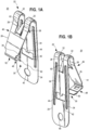
- FIGS. 1A through 3D illustrate an example clip 20 for use with a catenary cable or other similar objects, according to an embodiment of the invention.
- the clip 20 is illustrated in an open configuration, as may be useful for installation of the clip 20 on a catenary cable (not shown in FIGS. 1A-3D ).
- the clip 20 is illustrated in a closed configuration, as may be useful to secure the clip 20 in place on a catenary cable.
- a clip can be formed from spring steel.
- the clip 20 is illustrated as an integrally formed spring-steel stamping. In other embodiments, however, other configurations are possible.
- the clip 20 is integrally formed to include a hook portion 22.
- the hook portion 22 is configured to receive a catenary cable, in order to attach one or more objects (e.g., suspended an object from) the catenary cable.
- the hook portion 22 can be sized, in different embodiments, to receive a particular expected diameter of a catenary cable (e.g., a standard 6 mm cable).
- a hook portion can be configured to reliably receive and secure cable with a range of diameters.
- a load arm 24 and a locking arm 26 extend from opposite sides of the hook portion 22.
- load arms and locking arms can extend from a relevant hook portion with any variety of angular orientations.
- the load arm 26 is configured as a generally tangential extension of the hook portion 22.
- the locking arm 26 angles away from an opposite side of the hook portion 22, at bends 28, to angle away from the load arm 24 when the clip 20 is in the open configuration.
- a relatively wide-mouthed opening 30 is defined between the load and locking arms 24, 26, tapering inwardly toward the diameter of the hook portion 22.
- At least one of the load or the locking arms 24, 26 is generally configured to be flexible relative to the hook portion 22.
- the load and locking arms 24, 26 both extend from shared parallel bands 32 that also form the hook portion 22.
- the configuration of the bands 32 can provide an appropriate balance between flexibility and strength for some manually-installed catenary applications.
- a hook portion can be formed without bands, with bands that extend into one of a load or locking arm but not into the other, and so on.
- one of a load arm or a locking arm can be configured to be more flexible than the other, relative to a hook portion or other part of a clip.
- a set of reinforcement ribs 34 extend partly along opposite sides of the load arm 24 and partly onto the bands 32. Accordingly, the load arm 24 exhibits a greater stiffness against bending than the locking arm 26, and applying pressure to move the arms 24, 26 together may tend to flex the bands 32 to a greater extent near (or on) the locking arm 26 than near (or on) the load arm 24.
- This arrangement may be useful, for example, in order to provide a more stable mounting arrangement for objects to be attached to the clip 20. For example, with an object hanging from the load arm 24, it may be easier or otherwise more appropriate to move the locking arm 26 towards the load arm 24 than vice versa. In other embodiments, however, other configurations are possible.
- the load arm 24 includes an attachment opening configured as a round aperture 40 that extends fully through the load arm 24.
- the round aperture 40 can be used to attach an object in various ways, including through insertion of a rivet, an S-hook, or another fastener through the aperture 40. In this way, for example, a wide variety of objects can be secured to the clip 20, including mid-support cables, drop wire, other types of supports (e.g., J-hooks), or other objects. In other embodiments, however, attachment features other than an attachment opening can be provided.
- an object to be secured to a catenary cable by a catenary clip is secured to a locking set screw of the catenary clip. This may require the object to be rotated along with the set screw during installation, including to avoid the problems of kinked drop wires.
- using the aperture 40 to attach an object to the clip 20 can eliminate the need to rotate the object in this way. As also discussed below, this may result in improved ability to pre-fabricate hanging arrangements before securing them to catenary cable.
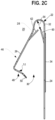
- a rivet 70 can be secured at the aperture 40 (not shown in FIG. 1C ) to secure an eyelet 72 and an associated drop wire 74 to the clip 20. With this arrangement, the clip 20 can be moved into alignment for installation and secured around a catenary cable (e.g., as discussed below) without the need to rotate an object supported by the drop wire 74.
- load and locking arms of a clip can include respective complementary engagement features that are configured to engage each other in order to secure the clip around a cable.
- the load arm 24 includes an opening configured as a substantially rectangular aperture 42, with a locking feature configured as a rectangular tab 44 that extends into the aperture 42.
- the locking arm 26 includes a spring portion 46 extending from the hook portion 22, and an engagement feature configured as a locking portion 48 that extends at an angle from the spring portion 46.
- the locking portion 48 extends at a substantially 90° angle from the spring portion 46.
- the locking portion 48 includes an end tab formed as an angled end 50 and a locking slot 52 that extends from the locking portion 48 onto the spring portion 46.
- cable-engagement features can be provided in order to help secure a cable within a hook portion.
- a cable-engagement feature includes one or more fingers that are configured to be urged into a cable to secure a clip thereto.
- the load and locking arms 24, 26 include cable-engagement features configured as fingers 60, 62.
- the fingers 60, 62 are configured to secure a cable against removal from the hook portion 22 when the clip 20 is in the open configuration, and to secure a cable against sliding within the hook portion 22 when the clip is in the closed configuration.
- cable-engagement fingers can be configured in a variety of ways, including as curved, angled, tapered, hooked, or other extensions.
- both of the fingers 60, 62 are configured as relatively rigid, tapered extensions of the respective arms 24, 26. Further, the fingers 60, 62 angle towards each other from opposing sides of the hook portion 22.
- Each of the fingers 60, 62 is somewhat flexible, so as to bend away from an expected diameter 64 of a cable (as also discussed below).
- Each is also substantially rigid against bending within the plane of the associated load arm 24 or locking arm 26, and is substantially rigid along its axis, in order to prevent buckling.
- the finger 60 extends inwardly at a somewhat sharper angle from the load arm 24 than the finger 62 does from the spring portion 46 of the locking arm 26. This may be useful, for example, to dispose the finger 62 to move more substantially relative to a cable as the locking arm 26 is moved towards the load arm 24 to close the clip.
- the fingers 60, 62 are configured to resiliently secure a cable within the hook portion 22 of the clip 20.
- each of the fingers 60, 62 extends inward into the opening 30, with the narrow ends of the fingers 60, 62 substantially aligned with, or slightly outside of, the expected diameter 64 of a cable.
- a cable with a diameter equal to or less than the diameter 64 can be seated manually within the clip 20.
- manual movement of the clip 20 onto a cable can urge the fingers 60, 62 outward for passage of the cable into the hook portion 22, and the fingers 60, 62 can thereafter spring back toward the orientation of FIG. 2C , to secure the cable within the hook portion 22.
- the fingers 60, 62 can allow axial movement of a cable within the hook portion 22, while the clip 20 is in the open configuration, as may be useful for adjustment of the clip 20 on the cable.
- FIGS. 3A through 3D illustrate the clip 20, in a closed configuration.
- pressure can be applied to urge the load and locking arms 24, 26 together.
- the hook portion 22 and the spring portion 46 of the locking arm 26 flex relative to the load arm 24 so that the locking portion 48 of the locking arm 26 passes partly into the aperture 42 on the load arm 24.
- the tab 44 on the load arm 24 can be seated within the locking slot 52 (see, e.g., FIG. 3C ), in order to secure the locking portion 48 within the aperture 42 and, thereby, to secure the clip 20 in the closed configuration.
- the clip 20 can be moved to or from the closed configuration manually and without tools.
- the angled end 50 can engage the tab 44 and thereby flex the locking portion 48 outwardly (i.e., downwardly in the orientation illustrated) to clear the tab 44. Once clear, the locking portion 48 can then spring resiliently into the load arm 24 to secure the tab 44 within the locking slot 52.
- the angled end 50 can be manually engaged in order to move the locking portion 48 clear of the tab 44, allowing the spring portion 46 to resiliently return the clip 20 to the open configuration.
- the load and locking arms 24, 26 extend substantially in parallel to each other. Further, the load arm 26 is configured to hang substantially straight downwardly, relative to gravity, when the clip 20 is closed and loaded.
- moving a clip to a closed configuration can help to secure a cable against movement relative to the clip as well as securing the cable generally within the clip.
- closing the clip 20 can generally close the hook portion 22 around a cable received therein, thereby effectively clamping the cable within the clip 20.
- moving the clip 20 to the closed configuration urges the free ends of the fingers 60, 62 into the interior of the expected diameter 64 of a cable.
- the fingers 60, 62 can accordingly be urged into the cable, to firmly secure the clip against radial or axial movement.
- the fingers 60, 62 can be urged past a resting (i.e., nominal) outer diameter of the cable, so that the free ends of the fingers 60, 62 somewhat deform, or penetrate into, the cable to provide particularly secure engagement.
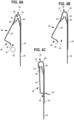
- FIGS. 4A-4C illustrate an example method of installing the clip 20 on a cable 80.
- the cable 80 can be aligned with the opening 30 and the clip 20 pulled downwardly, to move the cable upward between the load and locking arms 24, 26.
- the relatively large mouth of the opening 30, such as may be enabled by a spring-steel construction and the illustrated closing and locking mechanism, can be particularly useful.
- urging the cable 80 between the fingers 60, 62 can cause the fingers 60, 62 to flex away from each other, so that the cable 80 is admitted into the hook portion 22 (see FIG. 4B ).
- the fingers 60, 62 can then resiliently spring back to prevent the cable 80 from easily exiting the hook portion 22.
- the fingers 60, 62 and the hook portion 22 may still provide sufficient clearance for axial movement of the clip 20 along the cable 80 (or vice versa). This may be useful, for example, in order to adjust the clip 20 relative to the cable 80, even after the cable 80 has been secured within the clip 20, so as to support a particular object (not shown) at a desired location along the cable 80.
- the clip 20 can then be moved to the closed configuration.
- moving the clip 20 to the closed configuration can tighten the hook portion 22 around the cable and can also urge the fingers 60, 62 into the cable 80, such as may cause the free ends of the fingers 60, 62 to penetrate into the cable 80 (e.g., by locally compressing the cable or by penetrating between strands of the cable).
- the clip 20 when in the closed configuration, can be relatively firmly secured at a particular axial location on the cable 80, with the fingers 60, 62 strongly resisting any movement of the clip 20 axially along the cable 80. In this way, for example, the clip 20 can be adjusted when open, then effectively locked when closed, to firmly secure a particular object at a particular location along the cable 80.
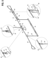
- FIG. 5 illustrates certain example uses of the clip 20, with the cable 80 suspended as a catenary cable between building structures (not shown).
- two of the clips 20 can be used with S-hooks 82 to hang an information plate from the cable.
- another of the clips 20 can be riveted to a support cable 84, then secured in an inverted orientation to the cable 80 in order for the support cable 84 to provide intermediate support for the catenary cable 80.
- two of the clips 20 can be engaged with corresponding J-hooks 86 in order to support an electrical cable 88 that extends in parallel with the cable 80.
- clips according to embodiments of the invention can allow for pre-fabricated systems to be easily secured to cables.
- drop wires 90 can be riveted to two of the clips 20 (e.g., similarly to FIG. 1C ) and also secured to a hanging light fixture 92. The clips 20 and the fixture 92 can then be lifted together and the clips 20 manually engaged with the cable 80, to hang the fixture 92 from the cable 80.
- the drop wires 90 are not secured to set screws or other similar features on the clips 20, the drop wires 90 do not need to be rotated during installation of the clips 20 in order to avoid twisting of the drop wires 90.
- a rivet used to secure the drop wires 90 can pivot freely relative to the clips 20, thereby generally providing flexibility with regard to certain movements of the clips 20 during installation.
- this arrangement can allow for relatively easy and versatile installation of pre-fabricated systems.
- the adjustability of the clips 20 relative to a cable when the clips 20 are in the open configuration can allow the objects to be easily and accurately moved to a desired location even while the objects are fully supported by the cable.
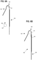
- FIGS. 6A and 6B illustrate a clip 100 according to an embodiment of an invention, which is generally configured to secure an object (not shown in FIGS. 6A and 6B ) to a cable 102.
- the clip 100 includes first and second arms 104, 106 that define an opening 108 to receive the cable 102. Further, the first and second arms 104, 106 can be flexed apart from each other to admit the cable 102, before resiliently springing back to the illustrated orientation with the cable 102 secured within the clip 100.
- the clip 100 is configured to operate differently than other configurations described herein.
- the arms 104, 106 are not necessarily configured to directly engage each other to secure the clip 100 to the cable 102.
- a finger 110 within the clip 100 is configured to be urged into, and thereby slightly compress, the cable 102, when the cable 102 is seated within the clip 100 and the arms 104, 106 resiliently close around the cable 102.
- a single one of the fingers 110 is provided, configured as a barb-like feature extending inwardly near a top end of the clip 100.
- embodiments of the invention provide an improved clip for attachment to cables.
- clips according to the invention can provide for improved ease of installation, including through a relatively wide opening to receive a cable and a configuration that allows manual movement of the clips between open and closed configurations.
- some clips according to the invention can allow for adjustment (e.g., axial sliding) of objects relative to a cable after the cable is engaged by the clip to support the object, while also providing selective locking of the clips against movement (e.g., axial sliding) on the cable.
Landscapes
- Engineering & Computer Science (AREA)
- General Engineering & Computer Science (AREA)
- Mechanical Engineering (AREA)
- Clamps And Clips (AREA)
Claims (14)
- Pince pour attacher un objet à un câble caténaire, la pince comprenant :un corps en une seule pièce comprenant :une partie crochet (22) conçue pour recevoir le câble caténaire (80) ;un bras de charge (24) s'étendant à partir de la partie crochet (22) pour la mise en prise de l'objet ;un bras de blocage (26) s'étendant à partir de la partie crochet (22) ; etla partie crochet (22) raccordant le bras de charge (24) au bras de blocage (26) de sorte que le bras de charge (24) et le bras de blocage (26) s'étendent à partir de la partie crochet (22) ;le corps en une seule pièce ayant une configuration ouverte dans laquelle le bras de charge (24) et le bras de blocage (26) définissent une ouverture (30) pour l'introduction du câble caténaire (80) dans la partie crochet (22) ;le corps en une seule pièce ayant une configuration fermée dans laquelle le bras de blocage (26) entre en prise avec le bras de charge (24) pour fermer la partie crochet (22) autour du câble caténaire (80) ; etdans laquelle la partie crochet (22) est conçue pour supporter la pince (20) relativement au câble caténaire (80) de sorte que le câble caténaire (80) soit placé contre la partie crochet (22), pour supporter un objet suspendu au bras de charge (24) relativement au câble caténaire (80) ; etdans laquelle le corps en une seule pièce comprend un doigt (62) qui s'étend dans une partie intérieure de la partie crochet (22), le doigt (62) étant conçu pour être poussé dans le câble caténaire (80), afin d'assujettir le câble caténaire (80) à l'intérieur de la partie crochet (22), lorsque le corps en une seule pièce est déplacé de la configuration ouverte à la configuration fermée.
- Pince selon la revendication 1, dans laquelle, lorsque le corps en une seule pièce se trouve dans la configuration fermée, le doigt (62) s'étend au-delà d'un périmètre extérieur du câble caténaire (80) et assujettit la pince (20) de sorte qu'elle ne puisse pas glisser le long du câble caténaire (80) lorsque le corps en une seule pièce se trouve dans la configuration fermée.
- Pince selon la revendication 1 ou la revendication 2, dans laquelle le doigt (62) est un premier doigt (62) ; etdans laquelle le corps en une seule pièce comprend, en outre, un second doigt (60) qui s'étend à partir du bras de charge (24), le second doigt (60) étant conçu pour être poussé dans le câble caténaire (80), afin d'assujettir le câble caténaire (80) à l'intérieur de la partie crochet (22), lorsque le corps en une seule pièce est déplacé de la configuration ouverte à la configuration fermée ; etéventuellement ou de préférence, dans laquelle le premier doigt (62) s'étend à partir du bras de blocage (26) et le second doigt (60) s'étend à partir du bras de charge (24).
- Pince selon la revendication 3, dans laquelle les premier et second doigts (62, 60) sont conçus pour entrer en prise avec le câble caténaire (80) en alignement circonférentiel l'un par rapport à l'autre.
- Pince selon l'une ou l'autre des revendications 3 et 4, dans laquelle au moins un des premier et second doigts (62, 60) s'étend dans la partie crochet (22), afin d'assujettir le câble caténaire (80) à l'intérieur de la partie crochet (22) lorsque le corps en une seule pièce se trouve dans la configuration ouverte.
- Pince selon la revendication 5, dans laquelle les premier et second doigts (62, 60) s'étendent dans la partie crochet (22) depuis des côtés opposés de la partie crochet (22).
- Pince selon l'une quelconque des revendications précédentes, dans laquelle le bras de blocage (26) comprend une partie élastique (46) s'étendant à partir de la partie crochet (22) et une partie de blocage (48) s'étendant de manière oblique relativement à la partie élastique (46), la partie de blocage (48) étant conçue pour entrer en prise avec le bras de charge (24) afin d'assujettir le corps en une seule pièce dans la configuration fermée, et
éventuellement ou de préférence, dans laquelle un élément de mise en prise de bras de blocage est formé sur la partie de blocage (48) de façon à faire corps avec celle-ci et est conçue pour entrer en prise avec un élément de mise en prise de bras de charge qui est formé sur le bras de charge (24) de façon à faire corps avec celui-ci, afin d'assujettir le corps en une seule pièce dans la configuration fermée. - Pince selon la revendication 7, dans laquelle l'élément de mise en prise de bras de blocage comprend une ouverture de bras de blocage (52) dans la partie de blocage (48) du bras de blocage (26) ; et
dans laquelle l'élément de mise en prise de bras de charge comprend une saillie de bras de charge (44) qui est conçue pour s'étendre dans l'ouverture de bras de blocage (52) afin d'assujettir le corps en une seule pièce dans la configuration fermée. - Pince selon la revendication 8, dans laquelle la saillie de bras de charge (44) est réalisée sous la forme d'une languette qui s'étend dans une ouverture de bras de charge (42) dans le bras de charge (24) ; et
dans laquelle au moins une portion de la partie de blocage (48) du bras de blocage (26) s'étend à travers l'ouverture de bras de charge (42) lorsque le corps en une seule pièce se trouve dans la configuration fermée. - Pince selon l'une quelconque des revendications précédentes, dans laquelle le corps en une seule pièce est conçu pour être dégagé à partir de la configuration fermée sans utiliser d'outils, et
éventuellement ou de préférence, dans laquelle le bras de blocage comprend une extrémité oblique (50) conçue pour être manipulée pour dégager la saillie de bras de charge (44) de l'ouverture de bras de blocage (52) . - Pince selon l'une quelconque des revendications précédentes, dans laquelle le bras de blocage (26) s'étend sensiblement parallèlement au bras de charge (24) lorsque le corps en une seule pièce se trouve dans la configuration fermée ; et
dans laquelle le corps en une seule pièce est conçu de façon à ce qu'on le fasse glisser manuellement le long du câble caténaire (80) lorsqu'il se trouve dans la configuration ouverte, et est conçu pour être assujetti de façon à ne pas pouvoir glisser le long du câble caténaire (80) lorsqu'il se trouve dans la configuration fermée. - Pince selon l'une quelconque des revendications précédentes, dans laquelle la partie crochet (22) est située à une première extrémité de la pince (20) et le bras de charge (24) s'étend de telle sorte qu'il s'éloigne de la première extrémité en direction d'une seconde extrémité opposée de la pince (20) ; etla pince (20) comprenant un élément d'attache (40) au niveau de la seconde extrémité du bras de charge (24) pour y attacher l'objet ;éventuellement ou de préférence, la partie crochet (22) est composée de bandes parallèles (32) raccordées à chacun du bras de charge (24) et du bras de blocage (26).
- Pince selon la revendication 12, dans laquelle le bras de blocage (26) entre en prise avec le bras de charge (24) à un emplacement entre la partie crochet (22) et l'élément d'attache (40).
- Procédé d'assujettissement d'un objet à un câble caténaire (80) au moyen d'une ou de plusieurs pinces (20), chacune desdites pinces (20) comprenant un corps en une seule pièce, le corps en une seule pièce comprenant une partie crochet (22) qui est conçue pour recevoir le câble caténaire (80), un bras de charge (24) qui s'étend à partir de la partie crochet (22) pour la mise en prise de l'objet et un bras de blocage (26) qui s'étend à partir de la partie crochet (22) en regard du bras de charge (24), le procédé comprenant, pour la ou chacune des pinces :insérer le câble caténaire (80) dans la partie crochet (22) par une ouverture (30) formée entre le bras de charge (24) et le bras de blocage (26) de telle sorte que le câble caténaire (80) soit placé dans la partie crochet (22) ;solliciter manuellement le bras de blocage (26) et le bras de charge (24) l'un vers l'autre afin de disposer le corps en une seule pièce dans une configuration fermée dans laquelle la partie crochet (22) est fermée autour du câble caténaire (80) de sorte que le corps en une seule pièce ne peut être retiré du câble caténaire (80) ; etsuspendre l'objet au bras de charge (24) de telle sorte que le câble caténaire (80) soutienne l'objet par le biais de la partie crochet (22) de la pince (20) ;dans lequel le fait de solliciter manuellement le corps en une seule pièce pour lui faire adopter la configuration fermée se traduit par le fait qu'au moins un doigt (62) du corps en une seule pièce est poussé dans le câble caténaire (80), à l'intérieur de la partie crochet (22), afin d'assujettir la pince (20) de façon à ce qu'elle ne puisse pas glisser axialement le long du câble caténaire (80).
Applications Claiming Priority (1)
| Application Number | Priority Date | Filing Date | Title |
|---|---|---|---|
| US201862668622P | 2018-05-08 | 2018-05-08 |
Publications (3)
| Publication Number | Publication Date |
|---|---|
| EP3567263A1 EP3567263A1 (fr) | 2019-11-13 |
| EP3567263B1 true EP3567263B1 (fr) | 2023-11-22 |
| EP3567263C0 EP3567263C0 (fr) | 2023-11-22 |
Family
ID=66542019
Family Applications (1)
| Application Number | Title | Priority Date | Filing Date |
|---|---|---|---|
| EP19173320.3A Active EP3567263B1 (fr) | 2018-05-08 | 2019-05-08 | Pince pour câble de caténaire |
Country Status (1)
| Country | Link |
|---|---|
| EP (1) | EP3567263B1 (fr) |
Family Cites Families (7)
| Publication number | Priority date | Publication date | Assignee | Title |
|---|---|---|---|---|
| US4958792A (en) * | 1989-05-09 | 1990-09-25 | B-Line Systems, Inc. | Clip for supporting conduit and the like |
| JPH03249494A (ja) * | 1989-11-17 | 1991-11-07 | Kyokuto Kogyo Kk | 配管用支持装置 |
| US5533696A (en) * | 1991-07-03 | 1996-07-09 | Erico International Corp. | Conduit clip |
| GB2288828B (en) * | 1994-04-18 | 1998-02-04 | Erico Int Corp | Hanger |
| US8459598B2 (en) * | 2009-04-14 | 2013-06-11 | Halex Co./Scott-Fetzer Company | Pipe hanger |
| WO2016004046A1 (fr) * | 2014-07-01 | 2016-01-07 | Boston Scientific Scimed, Inc. | Agrafe hémostatique ayant un dispositif de passage d'aiguille |
| NL2015404B1 (en) * | 2015-09-07 | 2017-03-22 | Walraven Holding Bv J Van | Conduit clip. |
-
2019
- 2019-05-08 EP EP19173320.3A patent/EP3567263B1/fr active Active
Also Published As
| Publication number | Publication date |
|---|---|
| EP3567263A1 (fr) | 2019-11-13 |
| EP3567263C0 (fr) | 2023-11-22 |
Similar Documents
| Publication | Publication Date | Title |
|---|---|---|
| US8474774B2 (en) | Panel component holder | |
| US20030185643A1 (en) | Flexible bridge for a strut nut | |
| US11619324B2 (en) | Structural fastener | |
| US20080295240A1 (en) | Shower Curtain Hanging Structure | |
| EP3369149B1 (fr) | Suspension de montage de câbles | |
| US10188006B2 (en) | Bracket mount assembly for light fixtures | |
| US11881694B2 (en) | Data cable support | |
| US9371962B2 (en) | Swivel cover assembly | |
| EP3567263B1 (fr) | Pince pour câble de caténaire | |
| EP2463578A1 (fr) | Dispositif de sécurisation d'appareils | |
| US20230296193A1 (en) | Flexible u-bolt assembly | |
| US20130322093A1 (en) | Light apparatus trim wireform | |
| US11784428B2 (en) | Structural fastener | |
| JP6090354B2 (ja) | コイルスプリングの圧縮保持治具 | |
| US10731829B2 (en) | Retention devices for recessed luminaires | |
| JP2020165495A (ja) | 連結具 | |
| EP2403083A1 (fr) | Guide de câbles, étrier et assemblage associé pour positionner et tenir des câbles sur des supports fixes | |
| CN212131546U (zh) | U形束带、开槽结构构件组件和支杆接纳件组件 | |
| CN210350740U (zh) | 悬垂线夹 | |
| JPH1026263A (ja) | 設備用配管支持金具 | |
| JPH08219123A (ja) | 固定治具 | |
| US10364576B2 (en) | Anchor | |
| JP6745517B1 (ja) | 物干しハンガーのピンチ取付け体取付け機構 | |
| EP0390834B1 (fr) | Pince d'arret a action rapide, dont la force de serrage est directement fonction de la charge, pour cables servant a suspendre des poids, tels que notamment des lustres | |
| RU146713U1 (ru) | Подвесной зажим для кабеля низкого напряжения |
Legal Events
| Date | Code | Title | Description |
|---|---|---|---|
| PUAI | Public reference made under article 153(3) epc to a published international application that has entered the european phase |
Free format text: ORIGINAL CODE: 0009012 |
|
| STAA | Information on the status of an ep patent application or granted ep patent |
Free format text: STATUS: THE APPLICATION HAS BEEN PUBLISHED |
|
| AK | Designated contracting states |
Kind code of ref document: A1 Designated state(s): AL AT BE BG CH CY CZ DE DK EE ES FI FR GB GR HR HU IE IS IT LI LT LU LV MC MK MT NL NO PL PT RO RS SE SI SK SM TR |
|
| AX | Request for extension of the european patent |
Extension state: BA ME |
|
| STAA | Information on the status of an ep patent application or granted ep patent |
Free format text: STATUS: REQUEST FOR EXAMINATION WAS MADE |
|
| 17P | Request for examination filed |
Effective date: 20200523 |
|
| RBV | Designated contracting states (corrected) |
Designated state(s): AL AT BE BG CH CY CZ DE DK EE ES FI FR GB GR HR HU IE IS IT LI LT LU LV MC MK MT NL NO PL PT RO RS SE SI SK SM TR |
|
| STAA | Information on the status of an ep patent application or granted ep patent |
Free format text: STATUS: EXAMINATION IS IN PROGRESS |
|
| 17Q | First examination report despatched |
Effective date: 20210715 |
|
| GRAP | Despatch of communication of intention to grant a patent |
Free format text: ORIGINAL CODE: EPIDOSNIGR1 |
|
| STAA | Information on the status of an ep patent application or granted ep patent |
Free format text: STATUS: GRANT OF PATENT IS INTENDED |
|
| INTG | Intention to grant announced |
Effective date: 20230621 |
|
| GRAS | Grant fee paid |
Free format text: ORIGINAL CODE: EPIDOSNIGR3 |
|
| GRAA | (expected) grant |
Free format text: ORIGINAL CODE: 0009210 |
|
| STAA | Information on the status of an ep patent application or granted ep patent |
Free format text: STATUS: THE PATENT HAS BEEN GRANTED |
|
| AK | Designated contracting states |
Kind code of ref document: B1 Designated state(s): AL AT BE BG CH CY CZ DE DK EE ES FI FR GB GR HR HU IE IS IT LI LT LU LV MC MK MT NL NO PL PT RO RS SE SI SK SM TR |
|
| REG | Reference to a national code |
Ref country code: GB Ref legal event code: FG4D |
|
| REG | Reference to a national code |
Ref country code: CH Ref legal event code: EP Ref country code: DE Ref legal event code: R096 Ref document number: 602019041768 Country of ref document: DE |
|
| REG | Reference to a national code |
Ref country code: IE Ref legal event code: FG4D |
|
| U01 | Request for unitary effect filed |
Effective date: 20231218 |
|
| U07 | Unitary effect registered |
Designated state(s): AT BE BG DE DK EE FI FR IT LT LU LV MT NL PT SE SI Effective date: 20231222 |
|
| PG25 | Lapsed in a contracting state [announced via postgrant information from national office to epo] |
Ref country code: GR Free format text: LAPSE BECAUSE OF FAILURE TO SUBMIT A TRANSLATION OF THE DESCRIPTION OR TO PAY THE FEE WITHIN THE PRESCRIBED TIME-LIMIT Effective date: 20240223 |
|
| PG25 | Lapsed in a contracting state [announced via postgrant information from national office to epo] |
Ref country code: IS Free format text: LAPSE BECAUSE OF FAILURE TO SUBMIT A TRANSLATION OF THE DESCRIPTION OR TO PAY THE FEE WITHIN THE PRESCRIBED TIME-LIMIT Effective date: 20240322 |
|
| PG25 | Lapsed in a contracting state [announced via postgrant information from national office to epo] |
Ref country code: ES Free format text: LAPSE BECAUSE OF FAILURE TO SUBMIT A TRANSLATION OF THE DESCRIPTION OR TO PAY THE FEE WITHIN THE PRESCRIBED TIME-LIMIT Effective date: 20231122 |
|
| PG25 | Lapsed in a contracting state [announced via postgrant information from national office to epo] |
Ref country code: IS Free format text: LAPSE BECAUSE OF FAILURE TO SUBMIT A TRANSLATION OF THE DESCRIPTION OR TO PAY THE FEE WITHIN THE PRESCRIBED TIME-LIMIT Effective date: 20240322 Ref country code: GR Free format text: LAPSE BECAUSE OF FAILURE TO SUBMIT A TRANSLATION OF THE DESCRIPTION OR TO PAY THE FEE WITHIN THE PRESCRIBED TIME-LIMIT Effective date: 20240223 Ref country code: ES Free format text: LAPSE BECAUSE OF FAILURE TO SUBMIT A TRANSLATION OF THE DESCRIPTION OR TO PAY THE FEE WITHIN THE PRESCRIBED TIME-LIMIT Effective date: 20231122 |
|
| PG25 | Lapsed in a contracting state [announced via postgrant information from national office to epo] |
Ref country code: RS Free format text: LAPSE BECAUSE OF FAILURE TO SUBMIT A TRANSLATION OF THE DESCRIPTION OR TO PAY THE FEE WITHIN THE PRESCRIBED TIME-LIMIT Effective date: 20231122 Ref country code: PL Free format text: LAPSE BECAUSE OF FAILURE TO SUBMIT A TRANSLATION OF THE DESCRIPTION OR TO PAY THE FEE WITHIN THE PRESCRIBED TIME-LIMIT Effective date: 20231122 Ref country code: NO Free format text: LAPSE BECAUSE OF FAILURE TO SUBMIT A TRANSLATION OF THE DESCRIPTION OR TO PAY THE FEE WITHIN THE PRESCRIBED TIME-LIMIT Effective date: 20240222 Ref country code: HR Free format text: LAPSE BECAUSE OF FAILURE TO SUBMIT A TRANSLATION OF THE DESCRIPTION OR TO PAY THE FEE WITHIN THE PRESCRIBED TIME-LIMIT Effective date: 20231122 |
|
| U20 | Renewal fee for the european patent with unitary effect paid |
Year of fee payment: 6 Effective date: 20240528 |
|
| PG25 | Lapsed in a contracting state [announced via postgrant information from national office to epo] |
Ref country code: CZ Free format text: LAPSE BECAUSE OF FAILURE TO SUBMIT A TRANSLATION OF THE DESCRIPTION OR TO PAY THE FEE WITHIN THE PRESCRIBED TIME-LIMIT Effective date: 20231122 |
|
| PG25 | Lapsed in a contracting state [announced via postgrant information from national office to epo] |
Ref country code: SK Free format text: LAPSE BECAUSE OF FAILURE TO SUBMIT A TRANSLATION OF THE DESCRIPTION OR TO PAY THE FEE WITHIN THE PRESCRIBED TIME-LIMIT Effective date: 20231122 |
|
| PG25 | Lapsed in a contracting state [announced via postgrant information from national office to epo] |
Ref country code: SM Free format text: LAPSE BECAUSE OF FAILURE TO SUBMIT A TRANSLATION OF THE DESCRIPTION OR TO PAY THE FEE WITHIN THE PRESCRIBED TIME-LIMIT Effective date: 20231122 Ref country code: SK Free format text: LAPSE BECAUSE OF FAILURE TO SUBMIT A TRANSLATION OF THE DESCRIPTION OR TO PAY THE FEE WITHIN THE PRESCRIBED TIME-LIMIT Effective date: 20231122 Ref country code: RO Free format text: LAPSE BECAUSE OF FAILURE TO SUBMIT A TRANSLATION OF THE DESCRIPTION OR TO PAY THE FEE WITHIN THE PRESCRIBED TIME-LIMIT Effective date: 20231122 Ref country code: CZ Free format text: LAPSE BECAUSE OF FAILURE TO SUBMIT A TRANSLATION OF THE DESCRIPTION OR TO PAY THE FEE WITHIN THE PRESCRIBED TIME-LIMIT Effective date: 20231122 |
|
| REG | Reference to a national code |
Ref country code: DE Ref legal event code: R097 Ref document number: 602019041768 Country of ref document: DE |
|
| PLBE | No opposition filed within time limit |
Free format text: ORIGINAL CODE: 0009261 |
|
| STAA | Information on the status of an ep patent application or granted ep patent |
Free format text: STATUS: NO OPPOSITION FILED WITHIN TIME LIMIT |
|
| 26N | No opposition filed |
Effective date: 20240823 |
|
| REG | Reference to a national code |
Ref country code: CH Ref legal event code: PL |
|
| PG25 | Lapsed in a contracting state [announced via postgrant information from national office to epo] |
Ref country code: MC Free format text: LAPSE BECAUSE OF FAILURE TO SUBMIT A TRANSLATION OF THE DESCRIPTION OR TO PAY THE FEE WITHIN THE PRESCRIBED TIME-LIMIT Effective date: 20231122 |
|
| PG25 | Lapsed in a contracting state [announced via postgrant information from national office to epo] |
Ref country code: MC Free format text: LAPSE BECAUSE OF FAILURE TO SUBMIT A TRANSLATION OF THE DESCRIPTION OR TO PAY THE FEE WITHIN THE PRESCRIBED TIME-LIMIT Effective date: 20231122 Ref country code: CH Free format text: LAPSE BECAUSE OF NON-PAYMENT OF DUE FEES Effective date: 20240531 |
|
| PG25 | Lapsed in a contracting state [announced via postgrant information from national office to epo] |
Ref country code: IE Free format text: LAPSE BECAUSE OF NON-PAYMENT OF DUE FEES Effective date: 20240508 |
|
| U20 | Renewal fee for the european patent with unitary effect paid |
Year of fee payment: 7 Effective date: 20250527 |
|
| PGFP | Annual fee paid to national office [announced via postgrant information from national office to epo] |
Ref country code: GB Payment date: 20250527 Year of fee payment: 7 |
|
| PG25 | Lapsed in a contracting state [announced via postgrant information from national office to epo] |
Ref country code: CY Free format text: LAPSE BECAUSE OF FAILURE TO SUBMIT A TRANSLATION OF THE DESCRIPTION OR TO PAY THE FEE WITHIN THE PRESCRIBED TIME-LIMIT; INVALID AB INITIO Effective date: 20190508 |
|
| PG25 | Lapsed in a contracting state [announced via postgrant information from national office to epo] |
Ref country code: HU Free format text: LAPSE BECAUSE OF FAILURE TO SUBMIT A TRANSLATION OF THE DESCRIPTION OR TO PAY THE FEE WITHIN THE PRESCRIBED TIME-LIMIT; INVALID AB INITIO Effective date: 20190508 |