EP3567355A1 - Jauge à vide - Google Patents
Jauge à vide Download PDFInfo
- Publication number
- EP3567355A1 EP3567355A1 EP17889729.4A EP17889729A EP3567355A1 EP 3567355 A1 EP3567355 A1 EP 3567355A1 EP 17889729 A EP17889729 A EP 17889729A EP 3567355 A1 EP3567355 A1 EP 3567355A1
- Authority
- EP
- European Patent Office
- Prior art keywords
- diaphragm
- introduction tube
- inner structure
- piezoelectric element
- airtight container
- Prior art date
- Legal status (The legal status is an assumption and is not a legal conclusion. Google has not performed a legal analysis and makes no representation as to the accuracy of the status listed.)
- Granted
Links
Images



Classifications
-
- G—PHYSICS
- G01—MEASURING; TESTING
- G01L—MEASURING FORCE, STRESS, TORQUE, WORK, MECHANICAL POWER, MECHANICAL EFFICIENCY, OR FLUID PRESSURE
- G01L21/00—Vacuum gauges
- G01L21/10—Vacuum gauges by measuring variations in the heat conductivity of the medium, the pressure of which is to be measured
-
- G—PHYSICS
- G01—MEASURING; TESTING
- G01L—MEASURING FORCE, STRESS, TORQUE, WORK, MECHANICAL POWER, MECHANICAL EFFICIENCY, OR FLUID PRESSURE
- G01L19/00—Details of, or accessories for, apparatus for measuring steady or quasi-steady pressure of a fluent medium insofar as such details or accessories are not special to particular types of pressure gauges
- G01L19/04—Means for compensating for effects of changes of temperature, i.e. other than electric compensation
-
- G—PHYSICS
- G01—MEASURING; TESTING
- G01L—MEASURING FORCE, STRESS, TORQUE, WORK, MECHANICAL POWER, MECHANICAL EFFICIENCY, OR FLUID PRESSURE
- G01L21/00—Vacuum gauges
-
- G—PHYSICS
- G01—MEASURING; TESTING
- G01L—MEASURING FORCE, STRESS, TORQUE, WORK, MECHANICAL POWER, MECHANICAL EFFICIENCY, OR FLUID PRESSURE
- G01L9/00—Measuring steady of quasi-steady pressure of fluid or fluent solid material by electric or magnetic pressure-sensitive elements; Transmitting or indicating the displacement of mechanical pressure-sensitive elements, used to measure the steady or quasi-steady pressure of a fluid or fluent solid material, by electric or magnetic means
-
- G—PHYSICS
- G01—MEASURING; TESTING
- G01L—MEASURING FORCE, STRESS, TORQUE, WORK, MECHANICAL POWER, MECHANICAL EFFICIENCY, OR FLUID PRESSURE
- G01L9/00—Measuring steady of quasi-steady pressure of fluid or fluent solid material by electric or magnetic pressure-sensitive elements; Transmitting or indicating the displacement of mechanical pressure-sensitive elements, used to measure the steady or quasi-steady pressure of a fluid or fluent solid material, by electric or magnetic means
- G01L9/0041—Transmitting or indicating the displacement of flexible diaphragms
- G01L9/008—Transmitting or indicating the displacement of flexible diaphragms using piezoelectric devices
Definitions
- the present invention relates to a vacuum gauge and other similar devices.
- Patent Document 1 discloses a physical quantity detector including a piezoelectric element having a base on each of opposite ends, and an airtight container (housing) to contain the piezoelectric element.
- the housing includes a ring portion to secure a diaphragm, a protruding portion that protrudes from the ring portion, two pillar members that vertically extend from the protruding portion, and a beam member that couples free ends of the two pillar members to each other.
- the base on one end of the piezoelectric element is secured to the diaphragm whereas the base on the other end of the piezoelectric element is secured to the beam member.
- the piezoelectric element When an external pressure is exerted on the diaphragm, the piezoelectric element is compressed or expanded in accordance with the external pressure. Correspondingly, the pressure received by the diaphragm causes a resonance frequency of the piezoelectric element to change so as to detect the pressure highly accurately based on the resonance frequency.
- Patent Document 1 JP-A-2013-104753
- An object of some aspects of the present invention is to provide a vacuum gauge that can suppress an influence of changes of outside temperature and accurately measure a vacuum degree.
- An object of other aspects of the present invention is to provide a vacuum gauge that allows for a displacement of one end of a piezoelectric element and reduces a displacement of the other end to accurately measure a vacuum degree.
- the stopper restricts displacement of the diaphragm, thereby making it possible to set the upper limit pressure allowable in the vacuum gauge.
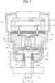
- FIG. 1 is a schematic cross-sectional view of a vacuum gauge according to an embodiment of the present invention.
- the vacuum gauge illustrated in FIG. 1 includes an airtight container 300, an inner structure 310 disposed in the airtight container 300, and an introduction tube 320 to which a gas to be measured is introduced.
- the introduction tube 320 includes a first portion 320A coupled to the inner structure 310 and surrounded by the airtight container 300.
- the introduction tube 320 may further include a second portion 320B coupled to the first portion 320A and protruding outward from the airtight container 300.
- a flange 110 is secured to a free end of the second portion 320B of the introduction tube 320.
- the flange 110 is secured to communicate with a chamber or a pipe that contains the gas to be measured.
- a piezoelectric element 50 is connected to a diaphragm 40.
- a bonding portion 60 to which one end of the piezoelectric element 50 is bonded is adhered and secured to a central portion of the diaphragm 40.
- the other end of the piezoelectric element 50 is secured to the inner structure 310.
- a crystal unit or preferably a double tuning fork crystal unit may be used for the piezoelectric element 50, which is displaced along with the diaphragm 40.
- the airtight container 300 is formed by airtightly combining, for example, a tubular member 30 and a partition wall 31. As illustrated in FIG. 1 , through the partition wall 31, two wires 32a and 32b connected to the piezoelectric element 50 are taken out while airtightness is maintained. In the case of providing a temperature sensor to measure a temperature in the vicinity of the piezoelectric element 50, two wires connected to the temperature sensor are additionally taken out through the partition wall 31.
- Another tubular member 100 is secured outside the partition wall 31, and circui t b oards 90 and 91 connected to the two wires 32a and 32b and other components are disposed in the tubular member 100.
- a voltage is applied between a pair of excitation electrodes of the piezoelectric element 50 to excite the piezoelectric element 50 at a natural resonance frequency.
- the resonance frequency decreases.
- the piezoelectric element 50 receives a tensile stress
- the resonance frequency increases. Consequently, based on the resonance frequency, the pressure is detected highly accurately.
- the first portion 320A of the introduction tube 320 and the inner structure 310 are airtightly enclosed by the airtight container 300, and the second portion 320B of the introduction tube 320 protrudes outward from the airtight container 300.
- the inner structure 310, the first portion 320A of the introduction tube 320, and the diaphragm 40 airtightly partition a space in the airtight container 300 into a pressure introduction chamber 130 on one surface side of the diaphragm 40, to which the gas to be measured is introduced, and a reference pressure chamber 120 on the other surface side of the diaphragm 40.
- the reference pressure chamber 120 is set at a high vacuum that is lower than the pressure lower limit of the gas to be measured.
- the pressure in the reference pressure chamber 120 may be set at 1/1000 or less or preferably 1/10000 or less of a minimum measurement pressure (pressure lower limit).
- a minimum measurement pressure (pressure lower limit) in the pressure introduction chamber 130 is set at 0.1 Pa
- the pressure in the reference pressure chamber 120 is set at 1/1000 or less of the minimum measurement pressure, that is, 1 x 10 -4 Pa or less to perform measurement with high accuracy of 0.1% or less without any effect by the pressure in the reference pressure chamber 120.
- a method that includes activating a bulk getter material in a high vacuum, performing chipping-off, and evacuating the reference pressure chamber 120 by a bulk getter pump may be adopted to maintain the reference pressure chamber 120 at 1 x 10 -4 Pa or less for a long term (for example, 30 years).
- the diaphragm 40 With the pressure introduction chamber 130 being set at an atmospheric pressure or a pressure by purge gas in an initial state, the diaphragm 40 is at a position displaced inside the reference pressure chamber 120 (or the diaphragm 40 is at a position restricted by a stopper 29, described later). Then, the gas to be measured in a vacuum chamber is introduced to the pressure introduction chamber 130 through the flange 110 and the introduction tube 320, and when the pressure introduction chamber 130 is evacuated, the diaphragm 40, which has been at the position inside the reference pressure chamber 120, is displaced outside the reference pressure chamber 120.
- the piezoelectric element 50 having one end connected to the diaphragm 40 has the other end secured to the inner structure 310, a stress is exerted on the piezoelectric element 50.
- the piezoelectric element 50 is connected to an oscillator circuit, and in response to the stress generated by displacement of the diaphragm 40 caused by the pressure, the frequency of the piezoelectric element 50 is changed.
- the frequency is divided into, for example, 1/64 by a frequency divider, and counted by a frequency counter to measure the pressure.
- an error caused by a temperature is corrected based on a measured temperature so as to measure the pressure more accurately.
- the reference pressure chamber 120 covers the other surface side of the diaphragm 40, the piezoelectric element 50, and the inner structure 310 supporting these components.
- the reference pressure chamber 120 is originally to set a reference pressure with respect to the pressure of the gas to be measured that is introduced to the pressure introduction chamber 130.
- a high vacuum of the reference pressure chamber 120 is made to function also as the vacuum heat-insulating portion to reduce an influence due to a temperature change, which is the most significant factor that causes the error of the vacuum gauge.
- the vacuum heat-insulating portion 120 suppresses convection heat transfer to sufficiently reduce the influence of outside temperature change caused by the convection and received by the piezoelectric element 50.
- the present embodiment includes the introduction tube 320, which extends inside and outside the airtight container 300 where the vacuum heat-insulating portion 120 is defined, and which is coupled to the inner structure 310 inside the airtight container 300. Due to solid heat conduction, therefore, the introduction tube 320 transfers outside heat to the inner structure 310.
- an inside tube (the first portion) 320A disposed inside the airtight container 300 is made of a low heat-transfer material such as zirconia (ZnO 2 ), which is an exemplary metal oxide, and the remainder, namely, an outside tube (the second portion) 320B is made of a metal such as stainless steel (SUS).
- the outside tube (the second portion) 320B or the whole introduction tube 320 may be made of a low heat-transfer material.
- At least one of the inside tube (the first portion) 320A and the outside tube (the second portion) 320B of the introduction tube 320 may be made of any low heat-transfer material insofar as the material suppresses heat transfer between a portion to which outside heat is transferred and the inner structure 310.
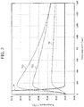
- FIG. 2 shows experiment data of temperatures T B , T C , and T D in the vicinity of the piezoelectric element 50 of three kinds of vacuum gauges when an outside temperature T A has been increased from 25°C to 30°C in 20 seconds.
- the temperature T D is a temperature in the vacuum gauge in the present embodiment illustrated in FIG. 1
- the temperatures T B and T C are temperatures in vacuum gauges in comparative examples 1 and 2.
- the vacuum gauge including the introduction tube 320 made of a metal (SUS) but not including the vacuum heat-insulating portion 120 of the vacuum gauge illustrated in FIG. 1 , has the temperature T B .
- the vacuum gauge includes the introduction tube 320 of the vacuum gauge in FIG.
- FIG. 2 apparently shows that the temperatures Tc and T D in the comparative example 2 and in the present embodiment, which include the vacuum heat-insulating portion 120, are kept by far lower than the temperature T B in the comparative example 1 without the vacuum heat-insulating portion 120. This clearly exhibits the effect of the vacuum heat-insulating portion 120.
- FIG. 3 further shows different experiment data.
- FIG. 3 shows temperatures T C1 and T C2 .
- the temperatures T C1 and T C2 are temperatures in vacuum gauges that include, in a similar manner to the comparative example 2 shown in FIG. 2 , the external pressure introduction tube 320 made of SUS, in addition to the vacuum heat-insulating portion 120. However, these vacuum gauges are different only in size of the introduction tube 320.
- the vacuum gauge in the present embodiment uses the introduction tube 320 of the same size as the comparative example 2-1.
- FIG. 3 shows that when the outside temperature T A has been increased from 25°C to 30°C in 20 seconds in the same manner as shown in FIG. 2 , the temperature T D in the present embodiment using the introduction tube 320 partly made of zirconia is kept lower than the temperatures T C1 and T C2 in the comparative examples 2-1 and 2-2 using the introduction tube 320 made of SUS304. It has been understood that although a temperature increase is suppressed in the comparative example 2-2 in which the introduction tube 320 has a smaller cross-sectional area than in the comparative example 2-1, a temperature increase is suppressed further in the present embodiment using the same size as the comparative example 2-1 than in the comparative example 2-2.
- An amount of solid heat conduction is reduced by decreasing a cross-sectional area of the introduction tube 320 or increasing the length L.
- At least one of the inside tube (the first portion) 320A and the outside tube (the second portion) 320B of the introduction tube 320 used in the present embodiment may be made of a material having a heat conductivity of 2 to 10 W/m ⁇ K, which is sufficiently lower than heat conductivities of general metals, preferably 2 to 7 W/m ⁇ K, more preferably 2 to 5 W/m ⁇ K.
- a calculation result of a temperature increase rate of the temperature T D in the present embodiment is 1 ⁇ 10 -4 °C/sec at maximum.
- the temperature increase rate in the vacuum gauge (in the vicinity of the piezoelectric element) in increasing the outside temperature from 25°C to 30°C in 20 seconds is 5 ⁇ 10 -3 (°C/sec) or less, temperature correction at approximately every two seconds becomes possible with temperature accuracy of at least 0.01°C to make measurement follow temperature correction on a real-time basis.
- the size of the first portion 320A may be changed to be smaller than the size of the second portion 320B (d1 ⁇ d3, d2 ⁇ d4).
- a first tube volume ( ⁇ .(d2/2) 2 ⁇ L1) of the first portion 320A of the introduction tube 320 may be made 1/2 to 1/6 of a second tube volume ( ⁇ (d4/2) 2 ⁇ L2) of the second portion 320B.
- a thickness [(d1 - d2)/2] of the first portion 320A is supposed to be substantially equal to a thickness [(d3 - d4)/2] of the second portion 320B.
- the heat conductivity is also decreased in proportion to the tube volume.
- a decrease in the tube volume causes a conductance of the introduction tube 320 to decrease, thereby leading to a reduction in a response speed of the vacuum gauge.
- the reduction in a response speed is almost non-critical when a volume of a pressure measurement chamber in the volume of the pressure introduction chamber 130, except for the volume of the introduction tube 320, is made decreased.
- the stopper 29 to restrict excessive displacement of the diaphragm 40 toward the inside of the airtight container 300 may be further disposed at the inner structure 310.
- the stopper 29 may be disposed on one of a proximal end portion 23, a reinforcement portion 25, and the bonding portion 60.
- a gap S is defined between the diaphragm 40 and the stopper 29 disposed on the proximal end portion 23 of the inner structure 310.
- the stopper 29 restricts displacement of the diaphragm 40 to avoid breakage of the piezoelectric element 50 at the upper limit of the pressure (high pressure) measured by the vacuum gauge and plastic deformation of the diaphragm 40.
- the stopper 29 disposed on the proximal end portion 23 or the reinforcement portion 25 of the inner structure 310 may restrict displacement of the diaphragm 40 or the bonding portion 60.
- FIGs. 4A and 4B are a plan view and a cross-sectional view of the inner structure 310.
- the inner structure 310 includes the proximal end portion 23 to which a circumferential edge portion of the diaphragm 40 and the first portion 320A of the introduction tube 320 are coupled, a securing portion 24 to which the other end (the upper end in FIG. 1 ) of the piezoelectric element 50 is secured, and the reinforcement portion 25 to which the proximal end portion 23 and the securing portion 24 are coupled.
- the diaphragm 40 to seal a first opening 21A of the proximal end portion 23 and the introduction tube 320 coupled to a second opening 21B of the proximal end portion 23 are airtightly secured by, for example, laser welding.
- the reinforcement portion 25 is a tubular member having a thickness "t", and the securing portion 24 is equivalent to a ceiling wall disposed on one end of the tubular member.
- the securing portion 24 has a bonding surface 26 to which a securing end portion of the piezoelectric element 50 is bonded.
- the reinforcement portion 25 steadfastly supports the securing portion 24 to which the other end of the piezoelectric element 50 is secured.
- the piezoelectric element 50 one end of which is displaced along with the diaphragm 40, has the other end secured and supported to the securing portion 24 so as to cause a stress dependent only on the pressure to be exerted on the piezoelectric element 50.
- the inner structure 310 includes a cut portion 27 in an angle range of (360° - ⁇ ) in plan view, and the cut portion 27 communicates with the hollow (the inner space of the reinforcement portion 25).
- ⁇ 270°
- at least one such as two holes 28A and 28B, extending through the securing portion 24 in an axial direction A in FIG. 1 is formed in the securing portion 24.
- FIGs. 5A and 5B are a plan view and a cross-sectional view of a state in which the bonding portion 60 is secured to the inner structure 310 held in a jig 200.
- positioning rods 201 are respectively inserted in the two holes 28A and 28B formed in the securing portion 24 of the inner structure 310.
- Two holes are formed in the bonding portion 60 in a similar manner to the securing portion 24 of the inner structure 310.
- Lower ends of the positioning rods 201 are also inserted in these two holes in a state illustrated in FIG.
- the bonding portion 60 is positioned with respect to the inner structure 310.
- the bonding portion 60 is, for example, adhered to the diaphragm 40.
- the two holes formed in the bonding portion 60 may be such non-through holes as to have bottom portions on a side where the diaphragm 40 is located.
- self-weights of the positioning rods 201 are utilized as weights in securing the bonding portion 60 to the diaphragm 40.
- additional weights may be coupled to the two positioning rods 201.
- the bonding portion 60 has a bonding surface (fourth plane) 61 to which a movable end (the lower end illustrated in FIG. 1 ) of the piezoelectric element 50 is bonded.
- the bonding surface 61 of the bonding portion 60 and the bonding surface 26 of the securing portion 24 are located on an identical line and in parallel to each other.
- the piezoelectric element 50 is made of a single-crystal quartz plate and has one end adhered to the bonding surface (second plane) 61 of the bonding portion 60 and the other end adhered to the bonding surface (fourth plane) 26 of the securing portion 24.
- disposing the piezoelectric element 50 and making the weights function with respect to the piezoelectric element 50 at the time of adhesion are performed through the cut portion 27. This improves workability.
- the securing portion 24 is integrally formed with the inner structure 310 including the first opening 21A sealed by the diaphragm 40.
- the securing portion 24 is coupled to the proximal end portion 23 with the reinforcement portion 25.
- the reinforcement portion 25 is formed in the range of (360°/N) (1 ⁇ N ⁇ 2) around the hollow where the piezoelectric element 50 is disposed. That is, the reinforcement portion 25 is disposed in the angle range of 180° or more and less than 360° around the piezoelectric element 50 so as to suppress deformation of the reinforcement portion 25. Consequently, even if a positive or negative pressure exerted on the diaphragm 40 is large, the secured end of the piezoelectric element 50 is not displaced with respect to the inner structure 310. This enables the piezoelectric element 50 to accurately detect the pressure exerted on the diaphragm 40 based on a displacement of the diaphragm 40.
- the present invention is not limited to the above-described embodiment, and various modifications are possible within the scope of the subject matter of the present invention.
- the configuration of the embodiment described above is also applicable to measurement devices to measure pressures other than a vacuum.
- the number N used for defining (360°/N) indicative of the range where the reinforcement portion is formed is most preferable when 1 ⁇ N ⁇ 2 as described above, pressure measurement with a predetermined accuracy is possible even when 1 ⁇ N ⁇ 4.
Landscapes
- Physics & Mathematics (AREA)
- General Physics & Mathematics (AREA)
- Measuring Fluid Pressure (AREA)
Applications Claiming Priority (3)
| Application Number | Priority Date | Filing Date | Title |
|---|---|---|---|
| JP2016001889 | 2016-01-07 | ||
| JP2017001298A JP2017125850A (ja) | 2016-01-07 | 2017-01-06 | 真空計 |
| PCT/JP2017/024139 WO2018127987A1 (fr) | 2016-01-07 | 2017-06-30 | Jauge à vide |
Publications (3)
| Publication Number | Publication Date |
|---|---|
| EP3567355A1 true EP3567355A1 (fr) | 2019-11-13 |
| EP3567355A4 EP3567355A4 (fr) | 2020-08-12 |
| EP3567355B1 EP3567355B1 (fr) | 2021-08-04 |
Family
ID=59364787
Family Applications (1)
| Application Number | Title | Priority Date | Filing Date |
|---|---|---|---|
| EP17889729.4A Active EP3567355B1 (fr) | 2016-01-07 | 2017-06-30 | Jauge à vide |
Country Status (6)
| Country | Link |
|---|---|
| US (1) | US10852207B2 (fr) |
| EP (1) | EP3567355B1 (fr) |
| JP (2) | JP2017125850A (fr) |
| KR (1) | KR102210827B1 (fr) |
| CN (1) | CN109618558B (fr) |
| WO (1) | WO2018127987A1 (fr) |
Families Citing this family (4)
| Publication number | Priority date | Publication date | Assignee | Title |
|---|---|---|---|---|
| KR102556708B1 (ko) | 2018-10-17 | 2023-07-17 | 큐즈 가부시키가이샤 | 압력계 |
| JP2020128920A (ja) * | 2019-02-08 | 2020-08-27 | 日立Geニュークリア・エナジー株式会社 | 使用済燃料貯蔵容器の閉じ込め機能確認装置 |
| JP7096628B1 (ja) | 2022-03-22 | 2022-07-06 | バキュームプロダクツ株式会社 | 隔膜圧力計及び複合圧力計 |
| CN115855361A (zh) * | 2022-12-06 | 2023-03-28 | 中国原子能科学研究院 | 压力测量装置 |
Family Cites Families (12)
| Publication number | Priority date | Publication date | Assignee | Title |
|---|---|---|---|---|
| US4198867A (en) * | 1977-09-19 | 1980-04-22 | The Foxboro Company | Temperature compensating means for pressure measuring apparatus |
| JPH02228585A (ja) * | 1989-03-01 | 1990-09-11 | Daiki:Kk | 電子晴雨計 |
| US5424598A (en) * | 1994-01-18 | 1995-06-13 | Corbett; James P. | Crystal force and pressure transducers |
| JP2001311673A (ja) * | 2000-04-28 | 2001-11-09 | Fujikura Ltd | 半導体圧力センサ |
| US20020033050A1 (en) * | 2000-04-28 | 2002-03-21 | Toshitaka Shibata | Pressure sensor |
| JP5187529B2 (ja) * | 2008-07-22 | 2013-04-24 | セイコーエプソン株式会社 | 圧力センサー |
| JP2012073163A (ja) * | 2010-09-29 | 2012-04-12 | Seiko Epson Corp | 圧力センサー |
| JP5915103B2 (ja) | 2011-11-11 | 2016-05-11 | セイコーエプソン株式会社 | 物理量検出器 |
| JP2014126423A (ja) * | 2012-12-26 | 2014-07-07 | Seiko Epson Corp | 圧力センサー、および真空装置 |
| US9116057B2 (en) * | 2013-02-27 | 2015-08-25 | Honeywell International Inc. | Integrated reference vacuum pressure sensor with atomic layer deposition coated input port |
| CN203908729U (zh) * | 2014-06-20 | 2014-10-29 | 浙江卡韦德新能源科技有限公司 | 车用真空传感器 |
| CN104568238B (zh) * | 2014-12-08 | 2018-02-23 | 太原航空仪表有限公司 | 压电激励谐振膜压力传感器 |
-
2017
- 2017-01-06 JP JP2017001298A patent/JP2017125850A/ja active Pending
- 2017-06-30 KR KR1020187037644A patent/KR102210827B1/ko active Active
- 2017-06-30 EP EP17889729.4A patent/EP3567355B1/fr active Active
- 2017-06-30 CN CN201780050129.5A patent/CN109618558B/zh active Active
- 2017-06-30 JP JP2018560314A patent/JP6744636B2/ja active Active
- 2017-06-30 WO PCT/JP2017/024139 patent/WO2018127987A1/fr not_active Ceased
-
2018
- 2018-12-06 US US16/211,384 patent/US10852207B2/en active Active
Also Published As
| Publication number | Publication date |
|---|---|
| JP2017125850A (ja) | 2017-07-20 |
| CN109618558A (zh) | 2019-04-12 |
| CN109618558B (zh) | 2021-10-26 |
| JP6744636B2 (ja) | 2020-08-19 |
| KR102210827B1 (ko) | 2021-02-02 |
| KR20190053817A (ko) | 2019-05-20 |
| EP3567355A4 (fr) | 2020-08-12 |
| EP3567355B1 (fr) | 2021-08-04 |
| JPWO2018127987A1 (ja) | 2019-11-07 |
| US10852207B2 (en) | 2020-12-01 |
| WO2018127987A1 (fr) | 2018-07-12 |
| US20190107458A1 (en) | 2019-04-11 |
Similar Documents
| Publication | Publication Date | Title |
|---|---|---|
| US10852207B2 (en) | Vacuum gauge | |
| US7819014B1 (en) | Capacitive gage pressure sensor with vacuum dielectric | |
| JP2012073163A (ja) | 圧力センサー | |
| US20120210799A1 (en) | Force detector | |
| US20120096945A1 (en) | Pressure sensor | |
| CN100549648C (zh) | 皮拉尼真空计 | |
| CN114334452B (zh) | 电容器结构及压力传感器 | |
| US11815420B2 (en) | Resonant pressure sensor with improved linearity | |
| CN111712697B (zh) | 压力计 | |
| KR20250102099A (ko) | 온도 오차에 대한 내성이 향상된 압력 트랜스듀서 | |
| JP4414746B2 (ja) | 静電容量型圧力センサ | |
| JP4377196B2 (ja) | 水晶摩擦真空計 | |
| JP7327695B2 (ja) | 振動式圧力センサ | |
| JP2012058063A (ja) | 圧力センサー | |
| US20120055267A1 (en) | Pressure sensor | |
| JP2009216719A (ja) | 圧力測定方法 | |
| JP2012058023A (ja) | 圧力センサー |
Legal Events
| Date | Code | Title | Description |
|---|---|---|---|
| STAA | Information on the status of an ep patent application or granted ep patent |
Free format text: STATUS: THE INTERNATIONAL PUBLICATION HAS BEEN MADE |
|
| PUAI | Public reference made under article 153(3) epc to a published international application that has entered the european phase |
Free format text: ORIGINAL CODE: 0009012 |
|
| STAA | Information on the status of an ep patent application or granted ep patent |
Free format text: STATUS: REQUEST FOR EXAMINATION WAS MADE |
|
| 17P | Request for examination filed |
Effective date: 20181213 |
|
| AK | Designated contracting states |
Kind code of ref document: A1 Designated state(s): AL AT BE BG CH CY CZ DE DK EE ES FI FR GB GR HR HU IE IS IT LI LT LU LV MC MK MT NL NO PL PT RO RS SE SI SK SM TR |
|
| AX | Request for extension of the european patent |
Extension state: BA ME |
|
| DAV | Request for validation of the european patent (deleted) | ||
| DAX | Request for extension of the european patent (deleted) | ||
| A4 | Supplementary search report drawn up and despatched |
Effective date: 20200714 |
|
| RIC1 | Information provided on ipc code assigned before grant |
Ipc: G01L 19/04 20060101ALI20200708BHEP Ipc: G01L 9/00 20060101ALI20200708BHEP Ipc: G01L 21/00 20060101AFI20200708BHEP |
|
| GRAP | Despatch of communication of intention to grant a patent |
Free format text: ORIGINAL CODE: EPIDOSNIGR1 |
|
| STAA | Information on the status of an ep patent application or granted ep patent |
Free format text: STATUS: GRANT OF PATENT IS INTENDED |
|
| INTG | Intention to grant announced |
Effective date: 20210319 |
|
| GRAS | Grant fee paid |
Free format text: ORIGINAL CODE: EPIDOSNIGR3 |
|
| GRAA | (expected) grant |
Free format text: ORIGINAL CODE: 0009210 |
|
| STAA | Information on the status of an ep patent application or granted ep patent |
Free format text: STATUS: THE PATENT HAS BEEN GRANTED |
|
| AK | Designated contracting states |
Kind code of ref document: B1 Designated state(s): AL AT BE BG CH CY CZ DE DK EE ES FI FR GB GR HR HU IE IS IT LI LT LU LV MC MK MT NL NO PL PT RO RS SE SI SK SM TR |
|
| REG | Reference to a national code |
Ref country code: GB Ref legal event code: FG4D |
|
| REG | Reference to a national code |
Ref country code: AT Ref legal event code: REF Ref document number: 1417441 Country of ref document: AT Kind code of ref document: T Effective date: 20210815 |
|
| REG | Reference to a national code |
Ref country code: CH Ref legal event code: EP |
|
| REG | Reference to a national code |
Ref country code: DE Ref legal event code: R096 Ref document number: 602017043625 Country of ref document: DE |
|
| REG | Reference to a national code |
Ref country code: IE Ref legal event code: FG4D |
|
| REG | Reference to a national code |
Ref country code: LT Ref legal event code: MG9D |
|
| REG | Reference to a national code |
Ref country code: NL Ref legal event code: MP Effective date: 20210804 |
|
| REG | Reference to a national code |
Ref country code: AT Ref legal event code: MK05 Ref document number: 1417441 Country of ref document: AT Kind code of ref document: T Effective date: 20210804 |
|
| PG25 | Lapsed in a contracting state [announced via postgrant information from national office to epo] |
Ref country code: PT Free format text: LAPSE BECAUSE OF FAILURE TO SUBMIT A TRANSLATION OF THE DESCRIPTION OR TO PAY THE FEE WITHIN THE PRESCRIBED TIME-LIMIT Effective date: 20211206 Ref country code: NO Free format text: LAPSE BECAUSE OF FAILURE TO SUBMIT A TRANSLATION OF THE DESCRIPTION OR TO PAY THE FEE WITHIN THE PRESCRIBED TIME-LIMIT Effective date: 20211104 Ref country code: LT Free format text: LAPSE BECAUSE OF FAILURE TO SUBMIT A TRANSLATION OF THE DESCRIPTION OR TO PAY THE FEE WITHIN THE PRESCRIBED TIME-LIMIT Effective date: 20210804 Ref country code: BG Free format text: LAPSE BECAUSE OF FAILURE TO SUBMIT A TRANSLATION OF THE DESCRIPTION OR TO PAY THE FEE WITHIN THE PRESCRIBED TIME-LIMIT Effective date: 20211104 Ref country code: AT Free format text: LAPSE BECAUSE OF FAILURE TO SUBMIT A TRANSLATION OF THE DESCRIPTION OR TO PAY THE FEE WITHIN THE PRESCRIBED TIME-LIMIT Effective date: 20210804 Ref country code: RS Free format text: LAPSE BECAUSE OF FAILURE TO SUBMIT A TRANSLATION OF THE DESCRIPTION OR TO PAY THE FEE WITHIN THE PRESCRIBED TIME-LIMIT Effective date: 20210804 Ref country code: SE Free format text: LAPSE BECAUSE OF FAILURE TO SUBMIT A TRANSLATION OF THE DESCRIPTION OR TO PAY THE FEE WITHIN THE PRESCRIBED TIME-LIMIT Effective date: 20210804 Ref country code: HR Free format text: LAPSE BECAUSE OF FAILURE TO SUBMIT A TRANSLATION OF THE DESCRIPTION OR TO PAY THE FEE WITHIN THE PRESCRIBED TIME-LIMIT Effective date: 20210804 Ref country code: FI Free format text: LAPSE BECAUSE OF FAILURE TO SUBMIT A TRANSLATION OF THE DESCRIPTION OR TO PAY THE FEE WITHIN THE PRESCRIBED TIME-LIMIT Effective date: 20210804 Ref country code: ES Free format text: LAPSE BECAUSE OF FAILURE TO SUBMIT A TRANSLATION OF THE DESCRIPTION OR TO PAY THE FEE WITHIN THE PRESCRIBED TIME-LIMIT Effective date: 20210804 |
|
| PG25 | Lapsed in a contracting state [announced via postgrant information from national office to epo] |
Ref country code: PL Free format text: LAPSE BECAUSE OF FAILURE TO SUBMIT A TRANSLATION OF THE DESCRIPTION OR TO PAY THE FEE WITHIN THE PRESCRIBED TIME-LIMIT Effective date: 20210804 Ref country code: LV Free format text: LAPSE BECAUSE OF FAILURE TO SUBMIT A TRANSLATION OF THE DESCRIPTION OR TO PAY THE FEE WITHIN THE PRESCRIBED TIME-LIMIT Effective date: 20210804 Ref country code: GR Free format text: LAPSE BECAUSE OF FAILURE TO SUBMIT A TRANSLATION OF THE DESCRIPTION OR TO PAY THE FEE WITHIN THE PRESCRIBED TIME-LIMIT Effective date: 20211105 |
|
| PG25 | Lapsed in a contracting state [announced via postgrant information from national office to epo] |
Ref country code: NL Free format text: LAPSE BECAUSE OF FAILURE TO SUBMIT A TRANSLATION OF THE DESCRIPTION OR TO PAY THE FEE WITHIN THE PRESCRIBED TIME-LIMIT Effective date: 20210804 |
|
| PG25 | Lapsed in a contracting state [announced via postgrant information from national office to epo] |
Ref country code: DK Free format text: LAPSE BECAUSE OF FAILURE TO SUBMIT A TRANSLATION OF THE DESCRIPTION OR TO PAY THE FEE WITHIN THE PRESCRIBED TIME-LIMIT Effective date: 20210804 |
|
| REG | Reference to a national code |
Ref country code: DE Ref legal event code: R097 Ref document number: 602017043625 Country of ref document: DE |
|
| PG25 | Lapsed in a contracting state [announced via postgrant information from national office to epo] |
Ref country code: SM Free format text: LAPSE BECAUSE OF FAILURE TO SUBMIT A TRANSLATION OF THE DESCRIPTION OR TO PAY THE FEE WITHIN THE PRESCRIBED TIME-LIMIT Effective date: 20210804 Ref country code: SK Free format text: LAPSE BECAUSE OF FAILURE TO SUBMIT A TRANSLATION OF THE DESCRIPTION OR TO PAY THE FEE WITHIN THE PRESCRIBED TIME-LIMIT Effective date: 20210804 Ref country code: RO Free format text: LAPSE BECAUSE OF FAILURE TO SUBMIT A TRANSLATION OF THE DESCRIPTION OR TO PAY THE FEE WITHIN THE PRESCRIBED TIME-LIMIT Effective date: 20210804 Ref country code: EE Free format text: LAPSE BECAUSE OF FAILURE TO SUBMIT A TRANSLATION OF THE DESCRIPTION OR TO PAY THE FEE WITHIN THE PRESCRIBED TIME-LIMIT Effective date: 20210804 Ref country code: CZ Free format text: LAPSE BECAUSE OF FAILURE TO SUBMIT A TRANSLATION OF THE DESCRIPTION OR TO PAY THE FEE WITHIN THE PRESCRIBED TIME-LIMIT Effective date: 20210804 Ref country code: AL Free format text: LAPSE BECAUSE OF FAILURE TO SUBMIT A TRANSLATION OF THE DESCRIPTION OR TO PAY THE FEE WITHIN THE PRESCRIBED TIME-LIMIT Effective date: 20210804 |
|
| PLBE | No opposition filed within time limit |
Free format text: ORIGINAL CODE: 0009261 |
|
| STAA | Information on the status of an ep patent application or granted ep patent |
Free format text: STATUS: NO OPPOSITION FILED WITHIN TIME LIMIT |
|
| 26N | No opposition filed |
Effective date: 20220506 |
|
| PG25 | Lapsed in a contracting state [announced via postgrant information from national office to epo] |
Ref country code: IT Free format text: LAPSE BECAUSE OF FAILURE TO SUBMIT A TRANSLATION OF THE DESCRIPTION OR TO PAY THE FEE WITHIN THE PRESCRIBED TIME-LIMIT Effective date: 20210804 |
|
| PG25 | Lapsed in a contracting state [announced via postgrant information from national office to epo] |
Ref country code: SI Free format text: LAPSE BECAUSE OF FAILURE TO SUBMIT A TRANSLATION OF THE DESCRIPTION OR TO PAY THE FEE WITHIN THE PRESCRIBED TIME-LIMIT Effective date: 20210804 |
|
| PG25 | Lapsed in a contracting state [announced via postgrant information from national office to epo] |
Ref country code: MC Free format text: LAPSE BECAUSE OF FAILURE TO SUBMIT A TRANSLATION OF THE DESCRIPTION OR TO PAY THE FEE WITHIN THE PRESCRIBED TIME-LIMIT Effective date: 20210804 |
|
| REG | Reference to a national code |
Ref country code: BE Ref legal event code: MM Effective date: 20220630 |
|
| PG25 | Lapsed in a contracting state [announced via postgrant information from national office to epo] |
Ref country code: LU Free format text: LAPSE BECAUSE OF NON-PAYMENT OF DUE FEES Effective date: 20220630 Ref country code: IE Free format text: LAPSE BECAUSE OF NON-PAYMENT OF DUE FEES Effective date: 20220630 |
|
| PG25 | Lapsed in a contracting state [announced via postgrant information from national office to epo] |
Ref country code: BE Free format text: LAPSE BECAUSE OF NON-PAYMENT OF DUE FEES Effective date: 20220630 |
|
| P01 | Opt-out of the competence of the unified patent court (upc) registered |
Effective date: 20230508 |
|
| PG25 | Lapsed in a contracting state [announced via postgrant information from national office to epo] |
Ref country code: HU Free format text: LAPSE BECAUSE OF FAILURE TO SUBMIT A TRANSLATION OF THE DESCRIPTION OR TO PAY THE FEE WITHIN THE PRESCRIBED TIME-LIMIT; INVALID AB INITIO Effective date: 20170630 |
|
| PG25 | Lapsed in a contracting state [announced via postgrant information from national office to epo] |
Ref country code: MK Free format text: LAPSE BECAUSE OF FAILURE TO SUBMIT A TRANSLATION OF THE DESCRIPTION OR TO PAY THE FEE WITHIN THE PRESCRIBED TIME-LIMIT Effective date: 20210804 Ref country code: CY Free format text: LAPSE BECAUSE OF FAILURE TO SUBMIT A TRANSLATION OF THE DESCRIPTION OR TO PAY THE FEE WITHIN THE PRESCRIBED TIME-LIMIT Effective date: 20210804 |
|
| PG25 | Lapsed in a contracting state [announced via postgrant information from national office to epo] |
Ref country code: MT Free format text: LAPSE BECAUSE OF FAILURE TO SUBMIT A TRANSLATION OF THE DESCRIPTION OR TO PAY THE FEE WITHIN THE PRESCRIBED TIME-LIMIT Effective date: 20210804 |
|
| PGFP | Annual fee paid to national office [announced via postgrant information from national office to epo] |
Ref country code: DE Payment date: 20250618 Year of fee payment: 9 |
|
| PGFP | Annual fee paid to national office [announced via postgrant information from national office to epo] |
Ref country code: GB Payment date: 20250620 Year of fee payment: 9 |
|
| PGFP | Annual fee paid to national office [announced via postgrant information from national office to epo] |
Ref country code: FR Payment date: 20250626 Year of fee payment: 9 |
|
| PGFP | Annual fee paid to national office [announced via postgrant information from national office to epo] |
Ref country code: CH Payment date: 20250701 Year of fee payment: 9 |
|
| PG25 | Lapsed in a contracting state [announced via postgrant information from national office to epo] |
Ref country code: TR Free format text: LAPSE BECAUSE OF FAILURE TO SUBMIT A TRANSLATION OF THE DESCRIPTION OR TO PAY THE FEE WITHIN THE PRESCRIBED TIME-LIMIT Effective date: 20210804 |