EP3567389B1 - Procédé de surveillance continue de l'isolation d'un agencement conducteur électrique - Google Patents
Procédé de surveillance continue de l'isolation d'un agencement conducteur électrique Download PDFInfo
- Publication number
- EP3567389B1 EP3567389B1 EP19171904.6A EP19171904A EP3567389B1 EP 3567389 B1 EP3567389 B1 EP 3567389B1 EP 19171904 A EP19171904 A EP 19171904A EP 3567389 B1 EP3567389 B1 EP 3567389B1
- Authority
- EP
- European Patent Office
- Prior art keywords
- conductor
- insulation
- arrangement
- insulation resistance
- active
- Prior art date
- Legal status (The legal status is an assumption and is not a legal conclusion. Google has not performed a legal analysis and makes no representation as to the accuracy of the status listed.)
- Active
Links
Images


Classifications
-
- G—PHYSICS
- G01—MEASURING; TESTING
- G01R—MEASURING ELECTRIC VARIABLES; MEASURING MAGNETIC VARIABLES
- G01R31/00—Arrangements for testing electric properties; Arrangements for locating electric faults; Arrangements for electrical testing characterised by what is being tested not provided for elsewhere
- G01R31/50—Testing of electric apparatus, lines, cables or components for short-circuits, continuity, leakage current or incorrect line connections
- G01R31/62—Testing of transformers
-
- H—ELECTRICITY
- H02—GENERATION; CONVERSION OR DISTRIBUTION OF ELECTRIC POWER
- H02H—EMERGENCY PROTECTIVE CIRCUIT ARRANGEMENTS
- H02H5/00—Emergency protective circuit arrangements for automatic disconnection directly responsive to an undesired change from normal non-electric working conditions with or without subsequent reconnection
- H02H5/10—Emergency protective circuit arrangements for automatic disconnection directly responsive to an undesired change from normal non-electric working conditions with or without subsequent reconnection responsive to mechanical injury, e.g. rupture of line, breakage of earth connection
- H02H5/105—Emergency protective circuit arrangements for automatic disconnection directly responsive to an undesired change from normal non-electric working conditions with or without subsequent reconnection responsive to mechanical injury, e.g. rupture of line, breakage of earth connection responsive to deterioration or interruption of earth connection
-
- G—PHYSICS
- G01—MEASURING; TESTING
- G01R—MEASURING ELECTRIC VARIABLES; MEASURING MAGNETIC VARIABLES
- G01R27/00—Arrangements for measuring resistance, reactance, impedance, or electric characteristics derived therefrom
- G01R27/02—Measuring real or complex resistance, reactance, impedance, or other two-pole characteristics derived therefrom, e.g. time constant
- G01R27/025—Measuring very high resistances, e.g. isolation resistances, i.e. megohm-meters
-
- G—PHYSICS
- G01—MEASURING; TESTING
- G01R—MEASURING ELECTRIC VARIABLES; MEASURING MAGNETIC VARIABLES
- G01R27/00—Arrangements for measuring resistance, reactance, impedance, or electric characteristics derived therefrom
- G01R27/02—Measuring real or complex resistance, reactance, impedance, or other two-pole characteristics derived therefrom, e.g. time constant
- G01R27/08—Measuring resistance by measuring both voltage and current
-
- G—PHYSICS
- G01—MEASURING; TESTING
- G01R—MEASURING ELECTRIC VARIABLES; MEASURING MAGNETIC VARIABLES
- G01R31/00—Arrangements for testing electric properties; Arrangements for locating electric faults; Arrangements for electrical testing characterised by what is being tested not provided for elsewhere
- G01R31/12—Testing dielectric strength or breakdown voltage ; Testing or monitoring effectiveness or level of insulation, e.g. of a cable or of an apparatus, for example using partial discharge measurements; Electrostatic testing
- G01R31/1227—Testing dielectric strength or breakdown voltage ; Testing or monitoring effectiveness or level of insulation, e.g. of a cable or of an apparatus, for example using partial discharge measurements; Electrostatic testing of components, parts or materials
-
- G—PHYSICS
- G01—MEASURING; TESTING
- G01R—MEASURING ELECTRIC VARIABLES; MEASURING MAGNETIC VARIABLES
- G01R31/00—Arrangements for testing electric properties; Arrangements for locating electric faults; Arrangements for electrical testing characterised by what is being tested not provided for elsewhere
- G01R31/50—Testing of electric apparatus, lines, cables or components for short-circuits, continuity, leakage current or incorrect line connections
- G01R31/52—Testing for short-circuits, leakage current or ground faults
-
- G—PHYSICS
- G01—MEASURING; TESTING
- G01R—MEASURING ELECTRIC VARIABLES; MEASURING MAGNETIC VARIABLES
- G01R31/00—Arrangements for testing electric properties; Arrangements for locating electric faults; Arrangements for electrical testing characterised by what is being tested not provided for elsewhere
- G01R31/50—Testing of electric apparatus, lines, cables or components for short-circuits, continuity, leakage current or incorrect line connections
- G01R31/58—Testing of lines, cables or conductors
-
- G—PHYSICS
- G01—MEASURING; TESTING
- G01R—MEASURING ELECTRIC VARIABLES; MEASURING MAGNETIC VARIABLES
- G01R27/00—Arrangements for measuring resistance, reactance, impedance, or electric characteristics derived therefrom
- G01R27/02—Measuring real or complex resistance, reactance, impedance, or other two-pole characteristics derived therefrom, e.g. time constant
- G01R27/14—Measuring resistance by measuring current or voltage obtained from a reference source
Definitions
- the invention relates to a method for continuously monitoring the insulation of an electrical conductor arrangement with an active conductor and a conductor structure that is electrically insulated from the active conductor.
- the normative requirements for insulation coordination for electrical equipment in low-voltage systems are described in the IEC 60664 series of standards. Specifications are made about air and creepage distances to be maintained and requirements for solid insulation are defined. This standard has the status of a basic safety standard and is therefore taken into account by a wide variety of installation and product standards as the basis for defining requirements in the area of insulation coordination.
- the research results show that the formation of migration effects can be detected in advance by a drop in the insulation resistance from 1 to 10 GOhm in good condition to values below 100 MOhm in bad condition.
- the first problem here is the non-availability of the supply system during the diagnostic measurements, secondly, the great effort involved in converting the system to enable diagnostic measurements, and thirdly, the unobserved times between the maintenance intervals.
- the disclosure document FR 2 781 574 A1 shows a system and method for safe power supply by detecting the insulation condition of a cable having conductors and a conductive jacket surrounding the conductors on the outside.
- a monitoring device with a DC voltage source to earth can be connected to the conductive sheath, so that external damage to the cable by an externally penetrating, earthed metal part leads to a current flow that is detected in the monitoring device and thus indicates the damaged insulation.
- the other patent DE 690 22 282 T2 describes a device for detecting an external impact in the form of excessive pinching of a cable assembly.
- the cable is surrounded by an outer layer of insulation, under which lies a semi-conductive layer which is connected to a display circuit. If the cable arrangement is excessively squeezed from the outside by a grounded body and the insulating layer is thus removed, this leads to a current flow via the semiconducting layer and the ground connection. This current flow is evaluated in the display circuit and excessive pinching is thus displayed.
- insulation monitoring technology which is particularly widespread in the low-voltage range, to assess the insulation status of systems, equipment or subsystems (printed circuit boards) seems conceivable, since the measurement technology in insulation monitoring devices is designed to be robust in order to deliver a correct measurement result under the influence of external and interference voltages.
- insulation monitoring devices are used in the field of oil and gas supply with a GOhm measuring range.
- parts of the power supply system have to be switched off using isolating devices, which is disadvantageous.
- insulation resistance measurements with regard to the insulation status of e.g. B. underwater supply cables (umbilical) meaningful.
- it is important to compare the measured values that were recorded at an initial or previous point in time.
- Standard insulation monitoring devices can only be used in unearthed power supply systems; it is not always possible to separate subsystems, e.g. B. not in medical applications, and shorter maintenance intervals in connection with extensive storage lead to higher costs.
- the present invention is based on the object of proposing a method that enables continuous insulation monitoring of an electrical conductor arrangement (power supply system) that includes a conductor structure that is electrically insulated from the active conductor.
- the method should be applicable in particular in cases in which the overall insulation resistance drops as a result of the interconnection of system parts, and for both grounded and ungrounded power supply systems.
- the active conductors can be insulated from ground, grounded with low resistance or grounded with high resistance. This covers all types of networks.
- the conductor structure is not only electrically insulated against the active conductors, but also against earth - in accordance with the measuring task - with very high resistance.
- the basic idea of the present invention is based on the assumption that a weakening of the insulation state due to possible influencing factors almost always has a symmetrical effect on the insulation and that this area of action is not limited to the active conductors of the conductor arrangement, but extends to neighboring conductor structures. For example, temperature-humidity cycles affect all areas of insulation exposed to these cycles.
- the measuring current flowing via this conductor structure, the insulation and via ground can advantageously form a measuring path that has a higher (insulation) resistance value, so that an insulation monitoring device that conforms to the standard can be used.
- the use of a standard-compliant insulation monitoring device for determining the insulation resistance is advantageous here, since a decreasing insulation level of the conductor arrangement can be expected to result in an increasing interference voltage level on the monitored conductor structure, but an insulation monitoring device based on the prior art is able to eliminate this interference voltage.
- one or more conductors of the conductor arrangement that do not carry operating current are used as the conductor structure.
- a shielding layer can advantageously be used as the conductor structure.
- the shielding layer can be electrically semiconductive or electrically conductive.
- an underwater supply line for example, it is conceivable to measure the insulation resistance between the semiconducting shielding layer and earth, in order to detect the ingress of water, for example.
- a capacitively grounded shield winding of the transformer can be used as the conductor structure.
- a decrease in the insulation resistance value measured between the capacitively earthed shield winding and earth, for example due to damp heat cycles, can be taken as an indicator of a critical condition of the transformer's insulation system.
- the method according to the invention for continuous insulation monitoring of an electrical conductor arrangement can be used in an advantageous manner in both an ungrounded and a grounded power supply system.
- the method according to the invention thus makes it possible to carry out continuous monitoring of the state of insulation of conductor arrangements independently of the type of network (grounded or ungrounded power supply system). Continuous monitoring during operation increases the electrical safety of the conductor arrangement to be monitored and avoids downtimes.
- the metrological possibilities of the current insulation monitoring technology up to the GOhm range can be used according to the invention for monitoring the conductor arrangement, in particular the cable insulation in electrical systems or for monitoring the insulation of equipment, advantageously even if the insulation level, for example of an unearthed power supply system, is too low would be to enable insulation monitoring according to the prior art.
- the method according to the invention is suitable for grounded power supply systems.
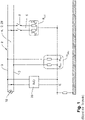
- a power supply system 2 which consists of a main system 4 and a subsystem 6 and is fed by a power source 10 .
- the main system 4 represents a conductor assembly 12 comprising two active conductors 3 includes.
- the conductor arrangement 12 is designed as an underwater supply line 28 (see 4 ) executed.
- the main system 4 and the subsystem 6 are each characterized by the insulation resistances R iso1 to R iso4 .
- a standardized insulation monitoring device 20 is connected between the active conductor 3 and earth E to measure the insulation resistance.
- the insulation monitoring device 20 superimposes a measuring voltage on the power supply system 2, the measuring circuit being closed to ground via the active conductor 3 and the insulation resistances R iso1 to R iso4 .
- the insulation resistance R umb of the main system 4 results from the parallel connection of the insulation resistance R iso1 and the insulation resistance R iso2
- the insulation resistance R sub of the subsystem 6 results from the parallel connection of the insulation resistance R iso3 and the insulation resistance R iso4 .
- the total insulation resistance of the power supply system 2 in turn results from the parallel connection of the insulation resistance R umb of the main system 4 and the insulation resistance R sub of the subsystem 6.
- the insulation level of the power supply system 2 drops.
- isolating switches 8 are provided for switching off the subsystem 6 . These isolating switches serve to separate the main system 4, which has a much higher resistance to ground, from the subsystem 6, which has a much lower resistance to ground.
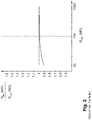
- the 2 shows in a diagram the ratio of the total insulation resistance R iso of the power supply system 2 to the insulation resistance R sub of the subsystem 6 as a function of the insulation resistance R umb of the main system 4.
- the expected slight change in the total insulation resistance value R iso determined by the insulation monitoring device 20 can be clearly seen when the subsystem 6 is connected in parallel with an insulation level of approx 4.
- the prerequisite applies that the insulating lacquer layer 15 with regard to the determination an insulation resistance exerts the same influence both on the active conductors 3, 13 and on the further conductor tracks 16.
- the other conductor tracks 16 are thus exposed to the same influencing factors that affect the quality of the insulation.
- the measurement of the total insulation resistance R iso on the conductor structure 14 thus allows an assessment of the insulating state of the common insulating lacquer layer 15 without the active conductors 3, 13 having to be subjected to a voltage.
- the 4 shows an application of the method according to the invention from the field of oil and gas supply, in which the conductor arrangement 12 is designed as an underwater supply line 28 .
- the underwater supply line 28 here encloses four active conductors 3 and four unused conductors 26 that do not carry operating current as a conductor structure 14.
- the insulation monitoring device 20 is coupled to this conductor structure 14, which consists of the unused conductors 26. Since here too the conductor structure 14 is exposed to the same environmental influences as the active conductor 3, an approximate estimate of the insulation state of the conductor arrangement 12 can be made here.
- a conductive or semiconductive shielding layer 36 of the conductor arrangement 12 designed as an underwater supply line 28 can be used as the conductor structure 14 .
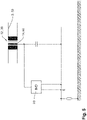
- FIG 5 an application of the method according to the invention is shown in connection with a conductor arrangement 12 which is designed as a transformer 38 .
- the transformer 38 comprises a conductor structure 14 designed as a shield winding 46.
- the insulation monitoring device 20 is coupled to this shield winding 46.
- the measuring current that flows in the measuring circuit that is closed via the shield winding 46 provides information about the insulation status of the transformer 38.
Landscapes
- Physics & Mathematics (AREA)
- General Physics & Mathematics (AREA)
- Engineering & Computer Science (AREA)
- Power Engineering (AREA)
- Measurement Of Resistance Or Impedance (AREA)
- Testing Of Short-Circuits, Discontinuities, Leakage, Or Incorrect Line Connections (AREA)
Claims (5)
- Procédé pour la surveillance continue d'isolement d'un armement de conducteur (12) électrique ayant un conducteur actif (3) et une structure de conducteur (14) isolée électriquement du conducteur actif (3), dans lequel la qualité de l'armement de conducteur (12) et l'armement du conducteur actif (3) et de la structure de conducteur (14) sont de telle manière que des conditions de propagation presque identiques s'appliquent pour le conducteur actif (3) et la structure de conducteur (14) pour un écoulement de courant mis à la terre (E) et de telle manière que des facteurs influents qui sont appropriés à influencer la résistance d'isolement de l'armement de conducteur (12) agissent de la même façon aussi bien sur le conducteur actif (3) que sur la structure de conducteur (14), le procédé comprenant les étapes suivantes :exécuter une mesure d'une résistance d'isolement, dans lequel un contrôleur d'isolement (20) adapté aux normes est connecté entre la structure de conducteur (14) et la terre (E) pour la détermination continue de la résistance d'isolement, dans lequel le contrôleur d'isolement (20) superpose une tension de mesure à l'armement de conducteur (12) électrique, dans lequel la tension de mesure génère un courant de mesure qui est proportionnel à la résistance d'isolement de l'armement de conducteur (12) et qui est enregistré dans le contrôleur (20) de mesure de résistance d'isolement et est évalué,dans lequel un ou plusieurs conducteurs (26) de l'armement de conducteur (12), qui ne transportent pas de courant d'emploi, sont utilisés comme structure de conducteur (14).
- Procédé pour la surveillance continue d'isolement d'un armement de conducteur (12) électrique ayant un conducteur actif (3) et une structure de conducteur (14) isolée électriquement du conducteur actif (3), dans lequel la qualité de l'armement de conducteur (12) et l'armement du conducteur actif (3) et de la structure de conducteur (14) sont de telle manière que des conditions de propagation presque identiques s'appliquent pour le conducteur actif (3) et la structure de conducteur (14) pour un écoulement de courant mis à la terre (E) et de telle manière que des facteurs influents qui sont appropriés à influencer la résistance d'isolement de l'armement de conducteur (12) agissent de la même façon aussi bien sur le conducteur actif (3) que sur la structure de conducteur (14), le procédé comprenant les étapes suivantes :exécuter une mesure d'une résistance d'isolement, dans lequel un contrôleur d'isolement (20) adapté aux normes est connecté entre la structure de conducteur (14) et la terre (E) pour la détermination continue de la résistance d'isolement, dans lequel le contrôleur d'isolement (20) superpose une tension de mesure à l'armement de conducteur (12) électrique, dans lequel la tension de mesure génère un courant de mesure qui est proportionnel à la résistance d'isolement de l'armement de conducteur (12) et qui est enregistré dans le contrôleur (20) de mesure de résistance d'isolement et est évalué,dans lequel une couche d'écran (36) est utilisée comme structure de conducteur (14).
- Procédé pour la surveillance continue d'isolement d'un armement de conducteur (12) électrique ayant un conducteur actif (3) et une structure de conducteur (14) isolée électriquement du conducteur actif (3), dans lequel la qualité de l'armement de conducteur (12) et l'armement du conducteur actif (3) et de la structure de conducteur (14) sont de telle manière que des conditions de propagation presque identiques s'appliquent pour le conducteur actif (3) et la structure de conducteur (14) pour un écoulement de courant mis à la terre (E) et de telle manière que des facteurs influents qui sont appropriés à influencer la résistance d'isolement de l'armement de conducteur (12) agissent de la même façon aussi bien sur le conducteur actif (3) que sur la structure de conducteur (14), le procédé comprenant les étapes suivantes :exécuter une mesure d'une résistance d'isolement, dans lequel un contrôleur d'isolement (20) adapté aux normes est connecté entre la structure de conducteur (14) et la terre (E) pour la détermination continue de la résistance d'isolement, dans lequel le contrôleur d'isolement (20) superpose une tension de mesure à l'armement de conducteur (12) électrique, dans lequel la tension de mesure génère un courant de mesure qui est proportionnel à la résistance d'isolement de l'armement de conducteur (12) et qui est enregistré dans le contrôleur (20) de mesure de résistance d'isolement et est évalué,dans lequel dans le cas d'un transformateur (38) comme armement de conducteur (12), un enroulement d'écran (46) mis à la terre de manière capacitive du transformateur (38) est utilisé comme structure de conducteur (14).
- Application du procédé selon l'une quelconque des revendications 1 à 3 pour la surveillance continue d'isolement d'un armement de conducteur (12) électrique d'un système d'alimentation (2) sans mise à la terre.
- Application du procédé selon l'une quelconque des revendications 1 à 3 pour la surveillance continue d'isolement d'un armement de conducteur électrique d'un système d'alimentation mis à la terre.
Applications Claiming Priority (1)
| Application Number | Priority Date | Filing Date | Title |
|---|---|---|---|
| DE102018111061.8A DE102018111061A1 (de) | 2018-05-08 | 2018-05-08 | Verfahren zur kontinuierlichen Isolationsüberwachung einer elektrischen Leiteranordnung |
Publications (2)
| Publication Number | Publication Date |
|---|---|
| EP3567389A1 EP3567389A1 (fr) | 2019-11-13 |
| EP3567389B1 true EP3567389B1 (fr) | 2022-06-01 |
Family
ID=66349328
Family Applications (1)
| Application Number | Title | Priority Date | Filing Date |
|---|---|---|---|
| EP19171904.6A Active EP3567389B1 (fr) | 2018-05-08 | 2019-04-30 | Procédé de surveillance continue de l'isolation d'un agencement conducteur électrique |
Country Status (4)
| Country | Link |
|---|---|
| US (1) | US11005256B2 (fr) |
| EP (1) | EP3567389B1 (fr) |
| CN (2) | CN210690686U (fr) |
| DE (1) | DE102018111061A1 (fr) |
Families Citing this family (2)
| Publication number | Priority date | Publication date | Assignee | Title |
|---|---|---|---|---|
| DE102018125004B3 (de) * | 2018-10-10 | 2019-12-12 | Bender Gmbh & Co. Kg | Elektrische Schaltungsanordnung und Verfahren zur Ankopplung eines Isolationsüberwachungsgerätes an ein ungeerdetes Stromversorgungssystem |
| CN111060848B (zh) * | 2019-12-31 | 2025-03-21 | 上海电缆研究所有限公司 | 半导电缓冲层电气的测试电路、评估方法及处理终端 |
Family Cites Families (24)
| Publication number | Priority date | Publication date | Assignee | Title |
|---|---|---|---|---|
| US4301399A (en) * | 1979-07-03 | 1981-11-17 | Perry Oceanographics, Inc. | Monitoring of electrical insulation integrity |
| US4988949A (en) * | 1989-05-15 | 1991-01-29 | Westinghouse Electric Corp. | Apparatus for detecting excessive chafing of a cable arrangement against an electrically grounded structure |
| FR2669738B1 (fr) * | 1990-11-28 | 1993-02-12 | Merlin Gerin | Controleur permanent d'isolement. |
| FR2781574B1 (fr) * | 1998-07-24 | 2000-10-06 | Regis Julien | Systeme et procede d'alimentation electrique securisee, et cable electrique mis en oeuvre dans ce systeme |
| US6265880B1 (en) * | 1999-06-15 | 2001-07-24 | The United States Of America As Represented By The Secretary Of The Air Force | Apparatus and method for detecting conduit chafing |
| DE10000551C1 (de) * | 2000-01-08 | 2001-07-05 | Bayerische Motoren Werke Ag | Vorrichtung zur Überwachung einer Batterieleitung |
| US7277822B2 (en) * | 2000-09-28 | 2007-10-02 | Blemel Kenneth G | Embedded system for diagnostics and prognostics of conduits |
| CN1320366C (zh) * | 2001-11-05 | 2007-06-06 | 北京深浪电子技术有限公司 | 高压输电线路绝缘子带电检测的方法及其装置 |
| DE10344421A1 (de) * | 2003-09-25 | 2005-04-28 | Daimler Chrysler Ag | Verwendung eines Kabels mit Lastleistung und Detektionsleitung zur Überstromerkennung |
| DE102005052956B3 (de) * | 2005-11-03 | 2007-05-31 | Ean Elektroschaltanlagen Gmbh | Verfahren und Einrichtung zur Isolationsfehlerortung in elektrischen Weichenheizungsanlagen |
| EP2344853A2 (fr) * | 2008-10-24 | 2011-07-20 | Nexans | Fil, système et procédé de détection d humidité |
| EP2256506B1 (fr) * | 2009-05-27 | 2019-07-03 | Bender GmbH & Co. KG | Procédé et dispositif de surveillance de l'isolation de réseaux à courant continu et à courant alternatif non mis à la terre |
| CN102095760A (zh) * | 2010-12-02 | 2011-06-15 | 广州文冲船厂有限责任公司 | 水下电缆漏水报警检测系统 |
| DE102012222251A1 (de) * | 2012-12-04 | 2014-06-05 | Bender Gmbh & Co. Kg | Isolationsüberwachungsgerät mit Messkreistrennung |
| WO2015075821A1 (fr) * | 2013-11-22 | 2015-05-28 | 三菱電機株式会社 | Détecteur d'isolation et dispositif électrique |
| CN103630813B (zh) * | 2013-12-05 | 2016-08-31 | 国网上海市电力公司 | 一种固体绝缘导体绝缘带电监测的方法 |
| CN203825089U (zh) * | 2014-02-27 | 2014-09-10 | 长沙三赫兹电气科技有限公司 | 一种变压器绝缘电阻的远程监控装置 |
| DE102014204038A1 (de) * | 2014-03-05 | 2015-09-10 | Bender Gmbh & Co. Kg | Verfahren und Vorrichtungen zur selektiven Isolationsüberwachung in ungeerdeten IT-Stromversorgungssystemen |
| GB2528502B (en) * | 2014-07-24 | 2018-06-13 | Ge Oil & Gas Uk Ltd | Power switching arrangement for line insulation monitoring |
| DE102015117678A1 (de) * | 2015-10-16 | 2017-04-20 | Bender Gmbh & Co. Kg | Isolationsfehler-Schutzeinrichtung mit Abschaltfunktion für ungeerdete Stromversorgungssysteme |
| CN106291109A (zh) * | 2016-07-27 | 2017-01-04 | 四川欧伦电气设备有限公司 | 一种绝缘连续检测装置 |
| DE102018110709A1 (de) * | 2018-05-04 | 2019-11-07 | Bender Gmbh & Co. Kg | Ankopplungsschaltung mit schaltender Funktion zur Ankopplung eines Isolationsüberwachungsgerätes an ein ungeerdetes Stromversorgungssystem |
| DE102018117296B4 (de) * | 2018-07-17 | 2020-02-20 | Bender Gmbh & Co. Kg | Verfahren und Vorrichtung zur Bestimmung der Aufteilung eines Gesamt-Isolationswiderstands und der Aufteilung einer Gesamt-Netzableitkapazität in einem ungeerdeten Stromversorgungssystem |
| DE102018121979A1 (de) * | 2018-09-10 | 2020-03-12 | Bender Gmbh & Co. Kg | Verfahren zur Isolationsüberwachung eines Umrichter-gespeisten Stromversorgungssystems |
-
2018
- 2018-05-08 DE DE102018111061.8A patent/DE102018111061A1/de active Pending
-
2019
- 2019-04-30 EP EP19171904.6A patent/EP3567389B1/fr active Active
- 2019-05-07 CN CN201920647674.9U patent/CN210690686U/zh not_active Expired - Fee Related
- 2019-05-07 US US16/404,820 patent/US11005256B2/en active Active
- 2019-05-07 CN CN201910375249.3A patent/CN110456151A/zh active Pending
Also Published As
| Publication number | Publication date |
|---|---|
| DE102018111061A1 (de) | 2019-11-14 |
| US11005256B2 (en) | 2021-05-11 |
| EP3567389A1 (fr) | 2019-11-13 |
| CN210690686U (zh) | 2020-06-05 |
| CN110456151A (zh) | 2019-11-15 |
| US20190348830A1 (en) | 2019-11-14 |
Similar Documents
| Publication | Publication Date | Title |
|---|---|---|
| DE3606697C2 (de) | Verfahren zum Prüfen der Beschädigung der Isolation eines Hochspannungskabels | |
| EP3598151B1 (fr) | Procédé et dispositif de détermination de la répartition d'une résistance totale d'isolement et de la répartition d'une capacité totale de dérivation du réseau dans un système d'alimentation en courant isolé terre | |
| DE69022282T2 (de) | Vorrichtung zur Anzeige übermässiger Quetschung einer Kabelanordnung gegen eine elektrisch geerdete Struktur. | |
| EP3524985B1 (fr) | Dispositif et procédé pour une surveillance de l'isolation à reconnaissance d'un conducteur extérieur défectueux dans un système d'alimentation électrique triphasé isolé terre | |
| DE102020102726B3 (de) | Verfahren zur Überwachung eines Erdwiderstands einer elektrischen Anlage | |
| DE69916299T2 (de) | Verfahren und vorrichtung zur erdschlusslokalisierung eines elektrischen kabels | |
| EP3139188B1 (fr) | Procédé et dispositif de recherche d'erreur d'isolation comprenant une détermination adaptative de courant de test | |
| EP3867651B1 (fr) | Dispositif de mesure, installation électrique comprenant un dispositif de mesure et procédé de mesure d'un courant de fuite | |
| DE102013207775B4 (de) | Vorrichtung zum Erkennen einer Störung einer elektrischen Leitung | |
| DE102015214615A1 (de) | Verfahren und Vorrichtungen zur erweiterten Isolationsfehlersuche mit multifunktionalem Prüfstrom | |
| EP3567389B1 (fr) | Procédé de surveillance continue de l'isolation d'un agencement conducteur électrique | |
| EP2863236B1 (fr) | Système de contrôle pour composants haute tension | |
| DE102016100671A1 (de) | Verfahren und Vorrichtung zur Kurzschlussüberwachung einer Drehstromlast | |
| DE69925946T2 (de) | Gerät und Verfahren zur Erfassung von Fehlern eines Kabelisolierungsmantels und Anlagen die sie benutzen | |
| EP3269015B1 (fr) | Procédé de détermination d'état et de localisation de défauts sur des dérivations isolées installées dans un système de protection extérieure contre la foudre | |
| DE102010013103B4 (de) | Vorrichtung und Verfahren zur Diagnose von Messobjekten unter Verwendung einer Messspannung | |
| DE102012100193B4 (de) | Photovoltaikanordnung, die eine Solaranlage und einen Solarwechselrichter umfasst, und Verfahren zum Betrieb einer solchen Photovoltaikanordnung | |
| DE10325389B4 (de) | Isolierungs-Prüfvorrichtung und Verfahren zur Prüfung der elektrischen Isolierung | |
| DE10257330A1 (de) | Messverfahren zur Früherkennung von eingedrungener Flüssigkeit in lang gestreckten Betriebsmitteln | |
| WO2020260674A1 (fr) | Dispositif et procédé de contrôle de câbles électriques cc blindés | |
| DE102023116532B3 (de) | Verfahren und elektrische Schaltungsanordnung zur selektiven Isolationsüberwachung in einem Stromversorgungssystem mit abtrennbaren Subsystemen | |
| EP4733791A1 (fr) | Procédés et dispositifs de contrôle et de surveillance de la continuité d'une ligne pen pour un système d'alimentation triphasée en courant tn-c | |
| DE19629481B4 (de) | Schaltungsanordnung für eine Hochspannungskabelanlage | |
| DE499797C (de) | Anordnung zum staendigen UEberwachen der Isolierfestigkeit des OEles elektrischer Apparate | |
| DE102010035882A1 (de) | Vorrichtung und Verfahren zur Ortung eines Erdschlusses an einem Kabel |
Legal Events
| Date | Code | Title | Description |
|---|---|---|---|
| PUAI | Public reference made under article 153(3) epc to a published international application that has entered the european phase |
Free format text: ORIGINAL CODE: 0009012 |
|
| STAA | Information on the status of an ep patent application or granted ep patent |
Free format text: STATUS: THE APPLICATION HAS BEEN PUBLISHED |
|
| AK | Designated contracting states |
Kind code of ref document: A1 Designated state(s): AL AT BE BG CH CY CZ DE DK EE ES FI FR GB GR HR HU IE IS IT LI LT LU LV MC MK MT NL NO PL PT RO RS SE SI SK SM TR |
|
| AX | Request for extension of the european patent |
Extension state: BA ME |
|
| STAA | Information on the status of an ep patent application or granted ep patent |
Free format text: STATUS: REQUEST FOR EXAMINATION WAS MADE |
|
| 17P | Request for examination filed |
Effective date: 20200512 |
|
| RBV | Designated contracting states (corrected) |
Designated state(s): AL AT BE BG CH CY CZ DE DK EE ES FI FR GB GR HR HU IE IS IT LI LT LU LV MC MK MT NL NO PL PT RO RS SE SI SK SM TR |
|
| REG | Reference to a national code |
Ref country code: DE Ref legal event code: R079 Ref document number: 502019004484 Country of ref document: DE Free format text: PREVIOUS MAIN CLASS: G01R0031020000 Ipc: G01R0031520000 |
|
| GRAP | Despatch of communication of intention to grant a patent |
Free format text: ORIGINAL CODE: EPIDOSNIGR1 |
|
| STAA | Information on the status of an ep patent application or granted ep patent |
Free format text: STATUS: GRANT OF PATENT IS INTENDED |
|
| RIC1 | Information provided on ipc code assigned before grant |
Ipc: G01R 27/14 20060101ALN20211207BHEP Ipc: G01R 31/62 20200101ALI20211207BHEP Ipc: G01R 31/58 20200101ALI20211207BHEP Ipc: G01R 31/52 20200101AFI20211207BHEP |
|
| INTG | Intention to grant announced |
Effective date: 20220105 |
|
| GRAA | (expected) grant |
Free format text: ORIGINAL CODE: 0009210 |
|
| GRAS | Grant fee paid |
Free format text: ORIGINAL CODE: EPIDOSNIGR3 |
|
| STAA | Information on the status of an ep patent application or granted ep patent |
Free format text: STATUS: THE PATENT HAS BEEN GRANTED |
|
| AK | Designated contracting states |
Kind code of ref document: B1 Designated state(s): AL AT BE BG CH CY CZ DE DK EE ES FI FR GB GR HR HU IE IS IT LI LT LU LV MC MK MT NL NO PL PT RO RS SE SI SK SM TR |
|
| REG | Reference to a national code |
Ref country code: GB Ref legal event code: FG4D Free format text: NOT ENGLISH |
|
| REG | Reference to a national code |
Ref country code: AT Ref legal event code: REF Ref document number: 1495750 Country of ref document: AT Kind code of ref document: T Effective date: 20220615 Ref country code: CH Ref legal event code: EP Ref country code: DE Ref legal event code: R096 Ref document number: 502019004484 Country of ref document: DE |
|
| REG | Reference to a national code |
Ref country code: IE Ref legal event code: FG4D Free format text: LANGUAGE OF EP DOCUMENT: GERMAN |
|
| REG | Reference to a national code |
Ref country code: LT Ref legal event code: MG9D |
|
| REG | Reference to a national code |
Ref country code: NL Ref legal event code: MP Effective date: 20220601 |
|
| PG25 | Lapsed in a contracting state [announced via postgrant information from national office to epo] |
Ref country code: SE Free format text: LAPSE BECAUSE OF FAILURE TO SUBMIT A TRANSLATION OF THE DESCRIPTION OR TO PAY THE FEE WITHIN THE PRESCRIBED TIME-LIMIT Effective date: 20220601 Ref country code: NO Free format text: LAPSE BECAUSE OF FAILURE TO SUBMIT A TRANSLATION OF THE DESCRIPTION OR TO PAY THE FEE WITHIN THE PRESCRIBED TIME-LIMIT Effective date: 20220901 Ref country code: LT Free format text: LAPSE BECAUSE OF FAILURE TO SUBMIT A TRANSLATION OF THE DESCRIPTION OR TO PAY THE FEE WITHIN THE PRESCRIBED TIME-LIMIT Effective date: 20220601 Ref country code: HR Free format text: LAPSE BECAUSE OF FAILURE TO SUBMIT A TRANSLATION OF THE DESCRIPTION OR TO PAY THE FEE WITHIN THE PRESCRIBED TIME-LIMIT Effective date: 20220601 Ref country code: GR Free format text: LAPSE BECAUSE OF FAILURE TO SUBMIT A TRANSLATION OF THE DESCRIPTION OR TO PAY THE FEE WITHIN THE PRESCRIBED TIME-LIMIT Effective date: 20220902 Ref country code: FI Free format text: LAPSE BECAUSE OF FAILURE TO SUBMIT A TRANSLATION OF THE DESCRIPTION OR TO PAY THE FEE WITHIN THE PRESCRIBED TIME-LIMIT Effective date: 20220601 Ref country code: ES Free format text: LAPSE BECAUSE OF FAILURE TO SUBMIT A TRANSLATION OF THE DESCRIPTION OR TO PAY THE FEE WITHIN THE PRESCRIBED TIME-LIMIT Effective date: 20220601 Ref country code: BG Free format text: LAPSE BECAUSE OF FAILURE TO SUBMIT A TRANSLATION OF THE DESCRIPTION OR TO PAY THE FEE WITHIN THE PRESCRIBED TIME-LIMIT Effective date: 20220901 |
|
| PG25 | Lapsed in a contracting state [announced via postgrant information from national office to epo] |
Ref country code: RS Free format text: LAPSE BECAUSE OF FAILURE TO SUBMIT A TRANSLATION OF THE DESCRIPTION OR TO PAY THE FEE WITHIN THE PRESCRIBED TIME-LIMIT Effective date: 20220601 Ref country code: PL Free format text: LAPSE BECAUSE OF FAILURE TO SUBMIT A TRANSLATION OF THE DESCRIPTION OR TO PAY THE FEE WITHIN THE PRESCRIBED TIME-LIMIT Effective date: 20220601 Ref country code: LV Free format text: LAPSE BECAUSE OF FAILURE TO SUBMIT A TRANSLATION OF THE DESCRIPTION OR TO PAY THE FEE WITHIN THE PRESCRIBED TIME-LIMIT Effective date: 20220601 |
|
| PG25 | Lapsed in a contracting state [announced via postgrant information from national office to epo] |
Ref country code: NL Free format text: LAPSE BECAUSE OF FAILURE TO SUBMIT A TRANSLATION OF THE DESCRIPTION OR TO PAY THE FEE WITHIN THE PRESCRIBED TIME-LIMIT Effective date: 20220601 |
|
| PG25 | Lapsed in a contracting state [announced via postgrant information from national office to epo] |
Ref country code: SM Free format text: LAPSE BECAUSE OF FAILURE TO SUBMIT A TRANSLATION OF THE DESCRIPTION OR TO PAY THE FEE WITHIN THE PRESCRIBED TIME-LIMIT Effective date: 20220601 Ref country code: SK Free format text: LAPSE BECAUSE OF FAILURE TO SUBMIT A TRANSLATION OF THE DESCRIPTION OR TO PAY THE FEE WITHIN THE PRESCRIBED TIME-LIMIT Effective date: 20220601 Ref country code: RO Free format text: LAPSE BECAUSE OF FAILURE TO SUBMIT A TRANSLATION OF THE DESCRIPTION OR TO PAY THE FEE WITHIN THE PRESCRIBED TIME-LIMIT Effective date: 20220601 Ref country code: PT Free format text: LAPSE BECAUSE OF FAILURE TO SUBMIT A TRANSLATION OF THE DESCRIPTION OR TO PAY THE FEE WITHIN THE PRESCRIBED TIME-LIMIT Effective date: 20221003 Ref country code: EE Free format text: LAPSE BECAUSE OF FAILURE TO SUBMIT A TRANSLATION OF THE DESCRIPTION OR TO PAY THE FEE WITHIN THE PRESCRIBED TIME-LIMIT Effective date: 20220601 Ref country code: CZ Free format text: LAPSE BECAUSE OF FAILURE TO SUBMIT A TRANSLATION OF THE DESCRIPTION OR TO PAY THE FEE WITHIN THE PRESCRIBED TIME-LIMIT Effective date: 20220601 |
|
| PG25 | Lapsed in a contracting state [announced via postgrant information from national office to epo] |
Ref country code: IS Free format text: LAPSE BECAUSE OF FAILURE TO SUBMIT A TRANSLATION OF THE DESCRIPTION OR TO PAY THE FEE WITHIN THE PRESCRIBED TIME-LIMIT Effective date: 20221001 |
|
| REG | Reference to a national code |
Ref country code: DE Ref legal event code: R097 Ref document number: 502019004484 Country of ref document: DE |
|
| PG25 | Lapsed in a contracting state [announced via postgrant information from national office to epo] |
Ref country code: AL Free format text: LAPSE BECAUSE OF FAILURE TO SUBMIT A TRANSLATION OF THE DESCRIPTION OR TO PAY THE FEE WITHIN THE PRESCRIBED TIME-LIMIT Effective date: 20220601 |
|
| PLBE | No opposition filed within time limit |
Free format text: ORIGINAL CODE: 0009261 |
|
| STAA | Information on the status of an ep patent application or granted ep patent |
Free format text: STATUS: NO OPPOSITION FILED WITHIN TIME LIMIT |
|
| PG25 | Lapsed in a contracting state [announced via postgrant information from national office to epo] |
Ref country code: DK Free format text: LAPSE BECAUSE OF FAILURE TO SUBMIT A TRANSLATION OF THE DESCRIPTION OR TO PAY THE FEE WITHIN THE PRESCRIBED TIME-LIMIT Effective date: 20220601 |
|
| 26N | No opposition filed |
Effective date: 20230302 |
|
| PG25 | Lapsed in a contracting state [announced via postgrant information from national office to epo] |
Ref country code: SI Free format text: LAPSE BECAUSE OF FAILURE TO SUBMIT A TRANSLATION OF THE DESCRIPTION OR TO PAY THE FEE WITHIN THE PRESCRIBED TIME-LIMIT Effective date: 20220601 |
|
| P01 | Opt-out of the competence of the unified patent court (upc) registered |
Effective date: 20230525 |
|
| REG | Reference to a national code |
Ref country code: CH Ref legal event code: PL |
|
| PG25 | Lapsed in a contracting state [announced via postgrant information from national office to epo] |
Ref country code: LU Free format text: LAPSE BECAUSE OF NON-PAYMENT OF DUE FEES Effective date: 20230430 |
|
| REG | Reference to a national code |
Ref country code: BE Ref legal event code: MM Effective date: 20230430 |
|
| PG25 | Lapsed in a contracting state [announced via postgrant information from national office to epo] |
Ref country code: MC Free format text: LAPSE BECAUSE OF FAILURE TO SUBMIT A TRANSLATION OF THE DESCRIPTION OR TO PAY THE FEE WITHIN THE PRESCRIBED TIME-LIMIT Effective date: 20220601 |
|
| PG25 | Lapsed in a contracting state [announced via postgrant information from national office to epo] |
Ref country code: MC Free format text: LAPSE BECAUSE OF FAILURE TO SUBMIT A TRANSLATION OF THE DESCRIPTION OR TO PAY THE FEE WITHIN THE PRESCRIBED TIME-LIMIT Effective date: 20220601 Ref country code: LI Free format text: LAPSE BECAUSE OF NON-PAYMENT OF DUE FEES Effective date: 20230430 Ref country code: IT Free format text: LAPSE BECAUSE OF FAILURE TO SUBMIT A TRANSLATION OF THE DESCRIPTION OR TO PAY THE FEE WITHIN THE PRESCRIBED TIME-LIMIT Effective date: 20220601 Ref country code: CH Free format text: LAPSE BECAUSE OF NON-PAYMENT OF DUE FEES Effective date: 20230430 |
|
| REG | Reference to a national code |
Ref country code: IE Ref legal event code: MM4A |
|
| PG25 | Lapsed in a contracting state [announced via postgrant information from national office to epo] |
Ref country code: BE Free format text: LAPSE BECAUSE OF NON-PAYMENT OF DUE FEES Effective date: 20230430 |
|
| PG25 | Lapsed in a contracting state [announced via postgrant information from national office to epo] |
Ref country code: IE Free format text: LAPSE BECAUSE OF NON-PAYMENT OF DUE FEES Effective date: 20230430 |
|
| PG25 | Lapsed in a contracting state [announced via postgrant information from national office to epo] |
Ref country code: IE Free format text: LAPSE BECAUSE OF NON-PAYMENT OF DUE FEES Effective date: 20230430 |
|
| PG25 | Lapsed in a contracting state [announced via postgrant information from national office to epo] |
Ref country code: BG Free format text: LAPSE BECAUSE OF FAILURE TO SUBMIT A TRANSLATION OF THE DESCRIPTION OR TO PAY THE FEE WITHIN THE PRESCRIBED TIME-LIMIT Effective date: 20220601 |
|
| PG25 | Lapsed in a contracting state [announced via postgrant information from national office to epo] |
Ref country code: BG Free format text: LAPSE BECAUSE OF FAILURE TO SUBMIT A TRANSLATION OF THE DESCRIPTION OR TO PAY THE FEE WITHIN THE PRESCRIBED TIME-LIMIT Effective date: 20220601 |
|
| REG | Reference to a national code |
Ref country code: AT Ref legal event code: MM01 Ref document number: 1495750 Country of ref document: AT Kind code of ref document: T Effective date: 20240430 |
|
| PGFP | Annual fee paid to national office [announced via postgrant information from national office to epo] |
Ref country code: DE Payment date: 20250417 Year of fee payment: 7 |
|
| PGFP | Annual fee paid to national office [announced via postgrant information from national office to epo] |
Ref country code: FR Payment date: 20250428 Year of fee payment: 7 |
|
| PG25 | Lapsed in a contracting state [announced via postgrant information from national office to epo] |
Ref country code: AT Free format text: LAPSE BECAUSE OF NON-PAYMENT OF DUE FEES Effective date: 20240430 |
|
| PG25 | Lapsed in a contracting state [announced via postgrant information from national office to epo] |
Ref country code: CY Free format text: LAPSE BECAUSE OF FAILURE TO SUBMIT A TRANSLATION OF THE DESCRIPTION OR TO PAY THE FEE WITHIN THE PRESCRIBED TIME-LIMIT; INVALID AB INITIO Effective date: 20190430 |
|
| PG25 | Lapsed in a contracting state [announced via postgrant information from national office to epo] |
Ref country code: HU Free format text: LAPSE BECAUSE OF FAILURE TO SUBMIT A TRANSLATION OF THE DESCRIPTION OR TO PAY THE FEE WITHIN THE PRESCRIBED TIME-LIMIT; INVALID AB INITIO Effective date: 20190430 |
|
| PG25 | Lapsed in a contracting state [announced via postgrant information from national office to epo] |
Ref country code: TR Free format text: LAPSE BECAUSE OF FAILURE TO SUBMIT A TRANSLATION OF THE DESCRIPTION OR TO PAY THE FEE WITHIN THE PRESCRIBED TIME-LIMIT Effective date: 20220601 |
|
| PGFP | Annual fee paid to national office [announced via postgrant information from national office to epo] |
Ref country code: GB Payment date: 20260324 Year of fee payment: 8 |
|
| PGFP | Annual fee paid to national office [announced via postgrant information from national office to epo] |
Ref country code: AT Payment date: 20260410 Year of fee payment: 5 |