EP3567560B1 - Cassette de notes de valeur - Google Patents
Cassette de notes de valeur Download PDFInfo
- Publication number
- EP3567560B1 EP3567560B1 EP18206627.4A EP18206627A EP3567560B1 EP 3567560 B1 EP3567560 B1 EP 3567560B1 EP 18206627 A EP18206627 A EP 18206627A EP 3567560 B1 EP3567560 B1 EP 3567560B1
- Authority
- EP
- European Patent Office
- Prior art keywords
- value
- storage area
- transport
- notes
- note
- Prior art date
- Legal status (The legal status is an assumption and is not a legal conclusion. Google has not performed a legal analysis and makes no representation as to the accuracy of the status listed.)
- Active
Links
Images


Classifications
-
- G—PHYSICS
- G07—CHECKING-DEVICES
- G07D—HANDLING OF COINS OR VALUABLE PAPERS, e.g. TESTING, SORTING BY DENOMINATIONS, COUNTING, DISPENSING, CHANGING OR DEPOSITING
- G07D11/00—Devices accepting coins; Devices accepting, dispensing, sorting or counting valuable papers
- G07D11/10—Mechanical details
- G07D11/12—Containers for valuable papers
-
- B—PERFORMING OPERATIONS; TRANSPORTING
- B65—CONVEYING; PACKING; STORING; HANDLING THIN OR FILAMENTARY MATERIAL
- B65H—HANDLING THIN OR FILAMENTARY MATERIAL, e.g. SHEETS, WEBS, CABLES
- B65H29/00—Delivering or advancing articles from machines; Advancing articles to or into piles
- B65H29/58—Article switches or diverters
- B65H29/60—Article switches or diverters diverting the stream into alternative paths
-
- G—PHYSICS
- G07—CHECKING-DEVICES
- G07D—HANDLING OF COINS OR VALUABLE PAPERS, e.g. TESTING, SORTING BY DENOMINATIONS, COUNTING, DISPENSING, CHANGING OR DEPOSITING
- G07D11/00—Devices accepting coins; Devices accepting, dispensing, sorting or counting valuable papers
- G07D11/10—Mechanical details
- G07D11/12—Containers for valuable papers
- G07D11/13—Containers for valuable papers with internal means for handling valuable papers
-
- G—PHYSICS
- G07—CHECKING-DEVICES
- G07D—HANDLING OF COINS OR VALUABLE PAPERS, e.g. TESTING, SORTING BY DENOMINATIONS, COUNTING, DISPENSING, CHANGING OR DEPOSITING
- G07D11/00—Devices accepting coins; Devices accepting, dispensing, sorting or counting valuable papers
- G07D11/20—Controlling or monitoring the operation of devices; Data handling
- G07D11/22—Means for sensing or detection
- G07D11/235—Means for sensing or detection for monitoring or indicating operating conditions; for detecting malfunctions
- G07D11/237—Means for sensing or detection for monitoring or indicating operating conditions; for detecting malfunctions for detecting transport malfunctions, e.g. jams or misfeeds
-
- G—PHYSICS
- G07—CHECKING-DEVICES
- G07D—HANDLING OF COINS OR VALUABLE PAPERS, e.g. TESTING, SORTING BY DENOMINATIONS, COUNTING, DISPENSING, CHANGING OR DEPOSITING
- G07D11/00—Devices accepting coins; Devices accepting, dispensing, sorting or counting valuable papers
- G07D11/40—Device architecture, e.g. modular construction
-
- B—PERFORMING OPERATIONS; TRANSPORTING
- B65—CONVEYING; PACKING; STORING; HANDLING THIN OR FILAMENTARY MATERIAL
- B65H—HANDLING THIN OR FILAMENTARY MATERIAL, e.g. SHEETS, WEBS, CABLES
- B65H2701/00—Handled material; Storage means
- B65H2701/10—Handled articles or webs
- B65H2701/19—Specific article or web
- B65H2701/1912—Banknotes, bills and cheques or the like
Definitions
- the invention relates to a value note cassette comprising a first storage area for storing first notes of value of a first value note type, wherein the first notes of value are storable in the first storage area in a first orientation, and a second storage area for storing second notes of value of a second value note type, which second storage area is separate from the first storage area.
- automated teller machines which comprise a value note cassette for storing notes of value of a first value note type, such as banknotes, and one or more further value note cassettes for storing notes of value of a second value note type, such as checks and/or banknotes suspected to be counterfeit and/or damaged banknotes and/or banknotes of another currency and/or banknotes of another denomination.
- a value note cassette for storing notes of value of a first value note type, such as banknotes
- a further value note cassettes for storing notes of value of a second value note type, such as checks and/or banknotes suspected to be counterfeit and/or damaged banknotes and/or banknotes of another currency and/or banknotes of another denomination.
- WO 2011/036806 A1 discloses a value note cassette with two storage areas. The notes in the first area are stored in a note stack with notes resting on their faces (notes are lying), whereas the second area stores a note stack wherein notes rest on their respective edges (notes are standing).
- a disadvantage of such solutions is that the automated teller machine has to be emptied whenever the first value note cassette is full, typically this is the value note cassette that stores banknotes.
- the automated teller machine already has to be emptied when the first value note cassette is full although the second value note cassette, due to a lower amount of checks, is only filled to some extent.
- the storage WN 18005 Ei capacity of the second value note cassette is not used optimally.
- a value note cassette comprising at least two separate storage areas, in which notes of value of different value note types are stored in a stacked manner upright on their long edges.
- the disadvantage of such solutions is that the storage capacity of the value note cassette is limited by the storage capacity of the storage area that is full first.
- the second notes of value are storable in the second storage area in a second orientation, the first orientation being orthogonal to the second orientation.
- the first orientation is in particular a horizontal orientation, i.e. the notes of value are stored in the first storage area lying on the face or back.
- the second orientation is in particular a vertical orientation, i.e. the notes of value are stored in the second storage area upright on the short or the long edge.
- the first storage area and the second storage area have WN 18005 Ei different spatial extents, in particular the first storage area has a larger volume than the second storage area.
- the second notes of value are stored in the second storage area upright on their short edge.
- the orientation of the notes of value is related to the position of the value note cassette when this cassette is inserted in an apparatus for handling notes of value in an intended installation position.
- first notes of value are banknotes and the second notes of value are checks.
- the storage capacity of the value note cassette is used optimally.
- a switch arrangement wherein in a first switch position of the switch arrangement notes of value fed to the value note cassette are feedable to a first transport path, wherein in a second switch position of the switch arrangement the notes of value fed to the value note cassette are feedable to a second transport path, and wherein the first transport path comprises a first transport unit and the second transport path comprises a second transport unit.
- the first transport unit comprises a circulating belt arrangement with an endless belt guided over rollers serving as deflecting elements.
- the belt comprises on its circumferential surface at least one transport tongue, into which at least an area of a first note of value of the first value note type is insertable after passing through the switch arrangement, and that at least one strip-off element is provided that contacts the first note of value for removal from the transport tongue, so that after removal from the transport tongue the note of value moves in one direction until it reaches a deposit element or until it reaches the upper note of value of a value note stack present on the deposit element.
- a safe transport of the notes of value and a safe deposit of the notes of value in the value note cassette are achieved.
- the second transport unit comprises a circulating belt arrangement with an endless belt guided over rollers serving as deflecting elements. It is particularly advantageous when the transport of the second notes of value through the second transport unit is caused by adhesive friction with the endless belt. As a result, a particularly simple, compact and cost-efficient structure of the second transport unit is achieved.
- first notes of value are transportable through the first transport unit in a first transport plane
- second notes of value are transportable through the second transport unit in a second transport plane
- first transport plane is orthogonal to the second transport plane
- the second storage area comprises a first press-on element which delimits the second storage area and is movable between a first position in which the second storage area has a minimum volume and a second position in which the second storage area has a maximum volume. It is further advantageous when the first storage area comprises a second press-on element which delimits the first storage area and is movable between a first position in which the first storage area has a minimum volume and a second position in which the first storage area has a maximum volume.
- the first notes of value are stored in the first storage area as a stack and when the second notes of value are stored in the second storage area as a stack.
- a particularly compact and safe storage of the notes of value in the first storage area and in the second storage area is achieved.
- the second transport unit comprises a guiding foil, the guiding foil being designed and arranged such that it separates the rear section, as viewed in transport direction, of a second note of value stored in WN 18005 Ei the second storage area and bearing against the endless belt from a front section, as viewed in transport direction, of a further second note of value during feeding into the second storage area.
- the extension of the second storage area in stacking direction corresponds to 8% to 30%, in particular 10% to 20%, of the extension of the first storage area in stacking direction.
- the first notes of value are stored in the first storage area lying on their face or back and when the second notes of value are stored in the second storage area upright on an edge, preferably upright on the short edge.
- the storage capacity of the first storage area and the storage capacity of the second storage area are utilized in a best-possible manner.
- the inventive arrangement comprises an apparatus for handling notes of value and at least one inventive value note cassette, wherein the value note cassette is insertable into the apparatus.
- At least one control unit and at least one sensor unit are provided in the arrangement, wherein the sensor unit detects whether a first note of value or a second note of value has been fed to the arrangement and, dependent on the value note type, outputs a sensor signal to the control unit, wherein the control unit controls a switch arrangement of the value note cassette dependent on the sensor signal.
- FIG 1 a schematic illustration of an apparatus 10 for handling notes of value is illustrated.
- the apparatus 10 is in particular an automatic cash safe, an automatic cash register system and/or an automated teller machine, such as a deposit machine for depositing notes of value 30, 32, in particular banknotes 30 and checks 32.
- the notes of value 30, 32 are illustrated in Figure 3 .
- the apparatus 10 comprises a head module 12 and a safe 14.
- Notes of value 30 of a first value note type and notes of value 32 of at least a second value note type are feedable to the apparatus 10 via a feed slot 14.
- the notes of value 30 of the first type are in particular banknotes 30, the notes of value 32 of the second type are in particular checks 32.
- the notes of value 30 of the first type can be banknotes 30 valid for monetary transactions
- the notes of value of the second type can be banknotes 30 suspected to be counterfeit and/or damaged banknotes 30 and/or banknotes 30 of another currency and/or banknotes 30 of another denomination.
- the apparatus 10 further comprises at least one control unit 28 and at least one sensor unit 36, wherein the sensor unit 36 at least detects whether a note of value 30 fed to the apparatus 10 is a note of value of the first value note type, in particular a banknote 30, or a note of value 32 of the second value note type, in particular a check 32, and outputs a sensor signal that is dependent on the value note type to the control unit 28.
- the sensor unit 36 at least detects whether a note of value 30 fed to the apparatus 10 is a note of value of the first value note type, in particular a banknote 30, or a note of value 32 of the second value note type, in particular a check 32, and outputs a sensor signal that is dependent on the value note type to the control unit 28.
- value note cassettes 16 which can store banknotes 30 and checks 32 are arranged in the safe 14.
- the storage of the notes of value 30, 32 is implemented as a split storage, i.e. in one value note cassette 16 both banknotes 30 and checks 32 are stored in a splitted manner, i.e. in different stacks.
- value note cassettes 16 can be provided in the safe 14.
- different types of value note cassettes can be used within the safe 14.
- At least one value note cassette 16 can be provided for the storage of banknotes 30 only and/or at least one value note cassette 16 can be provided for the storage of checks 32 only, or as a dispensing apparatus in which notes of value 30, 32 stored in the value note cassettes are only output or dispensed.
- the apparatus 10 is designed as a deposit-only apparatus so that notes of value 30, 32 are only fed to the value note cassettes 16 by the apparatus, but cannot be removed again.
- the apparatus 10 can also be designed as a recycling machine, in which notes of value 30, 32 can both be fed to the value note cassettes 16 and again be removed therefrom by the apparatus 10.
- the safe 14 has a transfer slot 18 through which the notes of value 30, 32 are transportable from the head module 12 to the safe 14. From the transport slot 18, the notes of value 30, 32 are transported via a transport unit identified with the reference sign 21 to the value note cassettes 16.
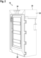
- FIG 2 shows a perspective illustration of the value note cassette 16 in its operating position. Elements having the same structure or the same function are identified with the same reference signs.
- the operating position is also referred to as vertical or upright position.
- the cash cassette 16 has a housing 20 with a cover 22, wherein the cover 22 can be opened so that access to the storage areas 150, 152 for storing notes of value 30, 32 that are provided inside the value note cassette 16 and are illustrated in Figure 3 is possible.
- the value note cassette 16 comprises a handle 24 at the top 23 for easy transport and a feed slot 110 visible in Figure 3 for feeding non-illustrated notes of value 30, 32.
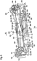
- FIG 3 shows a front view of the inner structure of the value note cassette 16 according to Figure 2 .
- the notes of value 30, 32 which, in this embodiment, are banknotes 30 and checks 32, are fed to the value note cassette 16 via the feed slot 110 and are fed to an input transport path T0 by first transport rollers 112 that are drivable by a non-illustrated drive unit and by press-on rollers 114 arranged opposite to the first transport rollers 112.
- the input transport path T0 is in particular delimited by a guide element 117 and by second transport rollers 118 which are arranged on a shaft 422 in a rotationally fixed manner.
- Press-on rollers 120 are arranged opposite to the second transport rollers 118 downstream along the input transport path T0.
- two transport rollers 112, 118 and two press-on rollers 114, 120 are visible, each of the rollers 112, 114, 118, 120 covering two further identical rollers positioned behind them, which are visible in Figure 6 .
- the input transport path T0 is adjoined by a switch area Y of a switch arrangement 122.
- the switch arrangement 122 comprises a switch body 124, a shaft 126 and a switch lever 123 illustrated in Figure 4 .
- a switch arrangement 122 in particular a switch arrangement disclosed in non-published document DE 10 2017 131 208.0 can be employed.
- the notes of value 30, 32 are guided by the switch body 124 and are fed to a first transport path T1 or a second transport path T2 dependent on the switch position of the switch body 124.
- the switch position of the switch body 124 is set by the control unit 28 via a corresponding control of a drive unit of the switch arrangement 122 in particular dependent on the value note type of the notes of value 30, 32 fed to the apparatus 10, which value note type is detected by the sensor unit 36.
- the control unit 28 determines for a note of value 30 fed to the apparatus 10 that it is a banknote 30, the switch arrangement 122 is controlled such that the switch body 124 is in a first switch body position P1 illustrated in Figure 5 , in which it bears against a mechanical stop 125 so that the banknotes 30 are fed to the first transport path T1.
- the banknotes 30 are stored in a first storage area 150 of the value note cassette 16 as a stack lying on their face or back.
- the transport elements of the first transport unit 200 form the first transport path T1 and in particular comprise deflecting rollers, of which in Figure 3 the deflecting roller 224 is visible, and a stacking belt arrangement 220.
- the transport unit 200, the transport elements and the first switch body position P1 are explained in the following in more detail in connection with Figure 5 .
- the switch arrangement 122 is controlled by the control unit 128 such that the switch body 124 is in the second switch body position P2 illustrated in Figure 3 .
- the checks 32 are directed to the second transport path T2, where they are guided via further transport rollers 130 and press-on rollers 132 and subsequently accepted by a second transport unit 300.
- the transport rollers 130 are arranged on a shaft 424 in a rotationally fixed manner. In Figure 3 , one transport roller 130 and one press-on roller 132 are shown, each of the rollers 130, 132 covering a further identical roller 133, 135 that is positioned behind of it, which are visible in Figure 6 .
- the second transport unit 300 comprises a circulating belt arrangement 310 with an endless belt 306 guided over rollers 302, 304 serving as deflecting elements, which endless belt forms a further section of the second transport path T2.
- the roller 304 is firmly connected to a drive shaft 316 that is driven by a drive unit 312.
- the second roller 302 is arranged on a shaft 318 in a rotationally fixed manner upstream of the roller 304 as viewed in transport direction R1.
- the rotation of the shaft 318 is transmitted via a gear train 402 illustrated in Figure 4 onto a shaft 320 that is connected in a rotationally fixed manner to a transport roller 308 arranged at the lower end of the transport path T2.
- the transport roller 308 is arranged opposite to the press-on roller 313. Further, the transport roller 308 covers two transport rollers lying behind it and visible in Figure 6 , one of which being arranged opposite to the belt 306.
- the checks 32 are stored in a second storage area 152 of the value note cassette 16.
- the second storage area 152 is delimited by a first press-on element 154 that is movable between a first position in which the second storage area 152 has a minimum volume and a second position in which the second storage area 152 has a maximum volume.
- Figure 3 in particular the second position A2 is shown, in which the storage area 154 has a maximum volume and is filled with checks 32 which are stacked upright on their short edges.
- the first press-on element 154 in particular comprises two scissors levers 156 and 160, a press-on plate 158, as well as an elastically deformable element that is not illustrated in Figure 3 and exerts a pressure on the press-on plate 158 for moving the press-on plate 158 in the direction of the first position.
- the first check is deposited in the second storage area 152 upright on its short edge and the transport of the second check 32 is stopped when the rear area of the second check 32 is still arranged between the transport rollers 308, the press-on rollers 313 and the endless belt 306 and the front area of the second check 32 is already pressed against the endless belt 306 by the first press-on element 154.
- Figure 3 further shows the first storage area 150 of the value note cassette 16, which is delimited by a motor-driven second press-on element 162 that is movable between a first position in which the first storage area 150 has a minimum volume and a second position in which the first storage area 150 has a maximum volume.
- the first storage area 150 is approximately half-filled with banknotes 30 that form a stack while lying on their face or back.
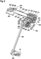
- Figure 4 shows a rear view of the inner structure of the value note cassette 16 according to Figure 3 .
- the illustration according to Figure 4 shows a first gear train 402 with four meshing gearwheels 404 to 410. Further, a second gear train 420 is illustrated that is engaged with a non-illustrated drive unit so that the shafts 422, 424 are driven.
- the switch lever 123 of the switch arrangement 122 is shown, the shaft 126, which is connected to the switch body 124 in a rotationally fixed manner, being rotatable about its longitudinal axis by the switch lever 123.
- the switch lever 123 is in particular engaged with an armature of a lifting magnet 450, wherein the lifting magnet 450 is controllable by the control unit 28 such that the armature is movable between a first armature position and a second armature position, wherein by the movement of the armature the switch lever 123 is pivoted about the axis of rotation of the shaft 126 so that the switch body 124 connected to the shaft 126 in a rotationally fixed manner is pivoted from the first into the second switch body position.
- the armature is covered by the switch lever 123.
- Figure 4 shows a stopper 460 that is a lateral guiding element when depositing the banknotes 30 by the first transport unit 200.
- Figure 5 shows the transport unit 200, by means of which the banknotes 30 are stored in the first storage area 150.
- a transport unit 200 in particular a transport unit as disclosed in the non-published document DE 10 2018 101 683.2 may be employed.
- the switch body 124 is in the first switch body position P1, in which the banknotes 30 are fed to the stacking belt arrangement 220 of the transport unit 200.
- the stacking belt arrangement 220 comprises four deflecting rollers of the type of a pulley, of which three deflecting rollers 222 to 226 are visible in Figure 5 .
- a first circulating stacking belt 230 is guided over the deflecting rollers 222, 224, the deflecting roller 222 being connected to the drive shaft 422 in a rotationally fixed manner.
- a second circulating stacking belt 232 is guided over the deflecting roller 226 and a second deflecting roller covered by the deflecting roller 222 in Figure 5 , the second deflecting roller being connected to the drive shaft 422 in a rotationally fixed manner.
- the inside of the stacking belts 230, 232 has a toothing, similar to a toothed belt, which engages with a complementary toothing of the deflecting rollers 224, 226.
- a positive connection of the stacking belts 230, 232 and the deflecting rollers 224, 226 is established so that slip between the stacking belts 230, 232 and the deflecting rollers 224, 226 is prevented.
- each of the stacking belts 230, 232 comprises two transport tongues, of which in the illustration of Figure 5 three transport tongues 234 to 238 are visible.
- the fourth transport tongue is visible in Figure 6 .
- the first transport tongue 234 of the first stacking belt 230 and the first transport tongue of the second stacking belt 232 which is not visible in the illustration according to Figure 5 , are arranged at the same height orthogonally to a circulating direction R2 of the stacking belts 230, 232, the second transport tongue 236 of the first stacking belt 230 and the second transport tongue 238 of the second stacking belt 232 are likewise arranged at the same height orthogonally to the circulating direction R2 of the stacking belts 230, 232.
- the control unit 28 controls the drive unit for driving the transport belts 230, 232 such that the first transport tongues 234 or the second transport tongues 236, 238 form by the deflection at the deflecting rollers 222 facing the switch arrangement 122 together with the circumferential surfaces of the stacking belts 230, 232 a respective open feed gap.
- a front area of the banknote 30 fed to the stacking unit 220 is received in this feed gap.
- the transport unit 200 comprises a contact element 250 which is pivotably connected to a counter pressure element 270.
- the contact element 250 comprises a lever arm 252 and an interrupter element 254.
- the contact element 250 is moved against gravity from the swiveled-away position S1 illustrated in Figure 5 in the direction of the counter-pressure element 270 into a swiveled-on position, the interrupter element 254 being moved into a recess 272 of the counter-pressure element 270.
- a light barrier that is not visible in Figure 5 is arranged in the recess 272.
- the light barrier comprises an optical sender for emitting light and an optical receiver for receiving the light emitted by the sender.
- the sender and the receiver are arranged such that upon passage of the interrupter element 254 between the optical sender and the optical receiver the light beam emitted by the sender is interrupted. This interruption is detected by the receiver.
- the receiver generates a sensor signal which is transmitted to the control unit 28 and is evaluated by the control unit 28.
- the banknote 30 remains in the first or second transport tongues 234 to 238 until these are deflected at the deflecting rollers 224, 226. Upon deflection, the feed gaps are opened and the banknote 30 is released. The banknote 30 still present in the transport tongues 234 to 238 is stopped at a strip-off element 260. The transport tongues 234 to 238 are moved further by means of the belts 230, 232 so that the banknotes 30 are removed from the transport tongues 234 to 238. The removal from the transport tongues 234 to 238 causes that the banknote 30 falls down and thus moves in a direction R3 parallel to the direction R1.
- the banknote 30 removed from the transport tongues 234 to 238 no longer holds the contact element 250 in the swiveled-on position so that the contact element 250 due to gravity moves in the direction of the swiveled-away position S1 and thus likewise in the direction R3 and in doing so contacts the banknote 30 until it hits an already deposited banknote stack or deposit elements 600, 602.
- the deposit element 600 is in particular pivotably mounted about an axis of rotation 604, the deposit element 602 is in particular pivotably mounted about an axis of rotation 606.
- the deposit elements 600, 602 are each oriented in a deposit position B1, B2 in which banknotes 30 can be deposited on the deposit elements 600, 602.
- the distance between the stacking belts 230, 232 and the deposit elements 600, 602 in their deposit position B1, B2 or the distance between the stacking belts 230, 232 and the banknote stack already deposited on the deposit elements 600, 602 defines a free space into which further banknotes 30 can be fed and stacked.
- the control unit 28 determines whether the free space is sufficiently large so that further banknotes can be stacked.
- the control unit 28 detects that the contact element 250 has been lifted from the already deposited banknotes 30 into the swiveled-on position and that no further banknotes 30 can be stacked in the free space 272.
- the control unit 28 controls a non-illustrated drive unit which moves the counter-pressure element 270 in the direction R3 by a predetermined distance.
- the counter-pressure element 270 is in particular movable in the direction R3 and opposite to the direction R3 by a gear arrangement 280 drivable by a non-illustrated drive unit.
- a movable slide 294 connected to the gear arrangement 280 is connected to the first scissors lever 282 via a shaft 283.
- the first scissors lever 282 is connected to a second scissors lever 284 via a shaft 286.
- the scissors lever 282, 284 are engaged with the counter-pressure element 270 via a respective shaft 288, 290.
- the movable slide 294 can be moved from the position illustrated in Figure 5 along a worm shaft 292 in the direction R2 and in a direction opposite to the direction R2.
- the scissors lever 282, 284 are forced apart, as a result whereof a movement of the counter-pressure element 270 in the direction R1 is caused.
- the banknote stack deposited on the deposit elements 600, 602 is pushed through the deposit elements 600, 602, while these are pivoted about the axes of rotation 604, 606.
- the control unit 28 controls the drive unit in particular such that the movement of the second press-on element 162 occurs dependent on the movement of the counter-pressure element 270.
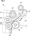
- Figure 6 shows a perspective view of the transport elements of the first transport unit 200 and of the second transport unit 300 according to Figures 2 to 5 .
- the transport rollers 119 and 121 covered by the transport roller 118, the transport roller 135 covered by the transport roller 130, the transport rollers 309 and 311 covered by the transport roller 308 and the press-on roller 133 covered by the press-on roller 132 in the illustration according to Figure 3 are visible.
- the deflecting roller 223 covered by the deflecting roller 222 in the illustration according to Figure 5 is visible in the illustration according to Figure 6 .
- the value note cassette 16 may comprise one or more control units additionally or alternatively to the control unit 28.
- Figure 7 shows a further side view of an inventive value note cassette 16 in an operating position in which a check 33 is held in a waiting position by the press-on roller 309 and the endless belt 306.
- Figure 8 shows a schematic detailed view of an alternative embodiment of an inventive value note cassette 16'. Elements having the same structure or the same function are identified with the same reference signs. Supplementary to the previous embodiments, a guiding foil 500 is provided in the value note cassette 16' according to Figure 8 .
- a first check 33 is arranged in the waiting position, wherein the rear section of the first check 33, as viewed in transport direction R1, is arranged between the transport path section 322 and the guiding foil 500 and the front section of the first check 33 bears against the transport belt 306.
- the guiding foil 500 separates the rear section of the first check 33 from the front section of the second check, as viewed in transport direction R1, wherein the guiding foil 500 is arranged between the first check 33 and the second check.
- the second check and the first check 33 are transported jointly in the direction R1, the first check 33 being deposited when contacting a deposit surface of the storage area 152.
- the second check After having been guided past the guiding foil 500, the second check is slowed down and is transported with the aid of the endless belt 306 so far opposite to the deposit direction R1 that its rear section, as viewed in transport direction R1, is arranged between the guiding foil 500 and the transport path section 322. Thus, the second check is now in the waiting position.
- Figure 9 shows a schematic perspective illustration of the value note cassette 16' according to Figure 8 .
- the press-on rollers 313 and 315 are visible.
Landscapes
- Physics & Mathematics (AREA)
- General Physics & Mathematics (AREA)
- Engineering & Computer Science (AREA)
- Mechanical Engineering (AREA)
- Pile Receivers (AREA)
- Sheets, Magazines, And Separation Thereof (AREA)
Claims (10)
- Cassette de notes de valeur, comprenantune première zone de stockage (150) pour stocker des premières notes de valeur (30) d'un premier type de note de valeur, les premières notes de valeur (30) pouvant être stockées dans la première zone de stockage (150) dans une première orientation,une seconde zone de stockage (152) pour stocker des secondes notes de valeur (32) d'un second type de note de valeur, laquelle seconde zone de stockage (152) étant séparée de la première zone de stockage (150),les secondes notes de valeur (32) pouvant être stockées dans la seconde zone de stockage (152) dans une seconde orientation, etla première orientation étant orthogonale à la seconde orientation,les premières notes de valeur (30) étant stockées dans la première zone de stockage (150) sous forme de pile et les secondes notes de valeur (32) étant stockées dans la seconde zone de stockage (152) sous forme de pile, les premières notes de valeur étant stockées dans la première zone de stockage couchées sur leur face ou leur dos et les secondes notes de valeur étant stockées dans la seconde zone de stockage debout sur le bord court, etun agencement de commutation (122) étant fourni, dans une première position de commutation (P1) de l'agencement de commutation (122), les notes de valeur (30, 32) alimentant la cassette de notes de valeur pouvant être acheminées vers un premier chemin de transport (T1), etdans une seconde position de commutation (P2) de l'agencement de commutation (122), les notes de valeur (30, 32) alimentant la cassette de notes de valeur (16) pouvant être acheminées vers un second chemin de transport (T2), et le premier chemin de transport (T1) comprenant une première unité de transport (200) et le second chemin de transport (T2) comprenant une seconde unité de transport (300),caractérisée en ce que la seconde unité de transport (300) comprend un agencement de courroie de circulation pourvu d'une courroie sans fin (306) guidée sur des rouleaux (302, 304) servant d'éléments de déviation et une feuille de guidage (500), la feuille de guidage (500) étant conçue et disposée de sorte à séparer la section arrière, vue dans le sens du transport (R1), d'une seconde note de valeur (33) stockée dans la seconde zone de stockage (152) et reposant contre la courroie sans fin (306), d'une section avant, vue dans le sens de transport (R1), d'une autre seconde note de valeur lors de l'alimentation dans la seconde zone de stockage (152), eten ce que la seconde zone de stockage (152) comprend un premier élément de pression (154) qui délimite la seconde zone de stockage et est mobile entre une première position dans laquelle la seconde zone de stockage (152) a un volume minimum et une seconde position (A2) dans laquelle la seconde zone de stockage (152) a un volume maximum.
- Cassette de notes de valeur selon la revendication 1, caractérisée en ce que les premières notes de valeur (30) sont des billets de banque (30) et les secondes notes de valeur (32) sont des chèques (32).
- Cassette de notes de valeur selon l'une des revendications précédentes, caractérisée en ce que la première unité de transport (200) comprend un agencement de courroie de circulation (310) pourvu d'une courroie sans fin (306) guidée sur des rouleaux (222 à 226) servant d'éléments de déviation.
- Cassette de notes de valeur selon la revendication 3, caractérisée en ce que la courroie (306) comprend sur sa surface circonférentielle au moins une languette de transport (234 à 238), dans laquelle au moins une zone d'une première note de valeur (30) du premier type de note de valeur peut être insérée après avoir traversé l'agencement de commutation (122), et en ce qu'au moins un élément de décollement (260) est fourni pour entrer en contact avec la première note de valeur (30) lors de son retrait de la languette de transport (234 à 238), de sorte qu'après son retrait de la languette de transport (234 à 238), la note de valeur (30) se déplace dans un sens (R3) jusqu'à ce qu'elle atteigne un élément de dépôt (600, 602) ou jusqu'à ce qu'elle atteigne la note de valeur (30) supérieure d'une pile de notes de valeur présente sur l'élément de dépôt (600, 602).
- Cassette de notes de valeur selon la revendication 6, caractérisée en ce que le transport des secondes notes de valeur (32) à travers la seconde unité de transport (300) est causé par la friction adhésive avec la courroie sans fin (306).
- Cassette de notes de valeur selon l'une des revendications précédentes, caractérisée en ce que les premières notes de valeur (30) sont transportables à travers la première unité de transport (200) dans un premier plan de transport, en ce que les secondes notes de valeur (32) sont transportables à travers la seconde unité de transport (300) dans un second plan de transport, et en ce que le premier plan de transport est orthogonal au second plan de transport.
- Cassette de notes de valeur selon l'une des revendications précédentes, caractérisée en ce que la première zone de stockage (150) comprend un second élément de pression (162) qui délimite la première zone de stockage (150) et qui est mobile entre une première position dans laquelle la première zone de stockage (150) a un volume minimum et une seconde position dans laquelle la première zone de stockage (150) a un volume maximum.
- Cassette de notes de valeur selon l'une des revendications précédentes, caractérisée en ce que l'extension de la seconde zone de stockage (152) dans le sens de l'empilement correspond à 8 % à 30 %, en particulier 10 % à 20 %, de l'extension de la première zone de stockage (150) dans le sens de l'empilement.
- Agencement comprenant un appareil de traitement de notes de valeur pourvu d'au moins une cassette de notes de valeur (16) selon l'une des revendications précédentes, la cassette de notes de valeur (16) pouvant être insérée dans l'appareil.
- Agencement selon la revendication 10, caractérisé en ce que l'agencement comprend au moins une unité de commande (28) et au moins une unité de détection (36), l'unité de détection (36) détectant si une première note de valeur (30) ou une seconde note de valeur (32) a été introduite dans l'agencement (10) et, en fonction du type de note de valeur, émet un signal de détection à l'unité de commande (28), l'unité de commande (28) commandant un agencement de commutation de la cassette de notes de valeur (16) en fonction du signal de détection.
Priority Applications (1)
| Application Number | Priority Date | Filing Date | Title |
|---|---|---|---|
| US16/404,100 US11066265B2 (en) | 2018-05-07 | 2019-05-06 | Value note cassette |
Applications Claiming Priority (1)
| Application Number | Priority Date | Filing Date | Title |
|---|---|---|---|
| EP18170966.8A EP3567559A1 (fr) | 2018-05-07 | 2018-05-07 | Cassette de notes de valeur |
Publications (2)
| Publication Number | Publication Date |
|---|---|
| EP3567560A1 EP3567560A1 (fr) | 2019-11-13 |
| EP3567560B1 true EP3567560B1 (fr) | 2025-04-02 |
Family
ID=62116781
Family Applications (2)
| Application Number | Title | Priority Date | Filing Date |
|---|---|---|---|
| EP18170966.8A Withdrawn EP3567559A1 (fr) | 2018-05-07 | 2018-05-07 | Cassette de notes de valeur |
| EP18206627.4A Active EP3567560B1 (fr) | 2018-05-07 | 2018-11-16 | Cassette de notes de valeur |
Family Applications Before (1)
| Application Number | Title | Priority Date | Filing Date |
|---|---|---|---|
| EP18170966.8A Withdrawn EP3567559A1 (fr) | 2018-05-07 | 2018-05-07 | Cassette de notes de valeur |
Country Status (2)
| Country | Link |
|---|---|
| US (1) | US10580247B2 (fr) |
| EP (2) | EP3567559A1 (fr) |
Families Citing this family (3)
| Publication number | Priority date | Publication date | Assignee | Title |
|---|---|---|---|---|
| DE102018101683B4 (de) * | 2018-01-25 | 2019-08-22 | Wincor Nixdorf International Gmbh | Vorrichtung zum Stapeln von Wertscheinen |
| US11066265B2 (en) * | 2018-05-07 | 2021-07-20 | Wincor Nixdor International GmbH | Value note cassette |
| CN111243162B (zh) * | 2020-01-15 | 2022-11-22 | 山东新北洋信息技术股份有限公司 | 纸币集积装置的控制方法、装置和现金处理设备 |
Family Cites Families (9)
| Publication number | Priority date | Publication date | Assignee | Title |
|---|---|---|---|---|
| JP4408373B2 (ja) * | 2004-01-23 | 2010-02-03 | 日立オムロンターミナルソリューションズ株式会社 | 紙幣入出金装置 |
| JP4704777B2 (ja) * | 2004-06-01 | 2011-06-22 | 日立オムロンターミナルソリューションズ株式会社 | 紙幣入出金機 |
| DE102008003957A1 (de) | 2007-06-01 | 2008-12-11 | Knorr-Bremse Systeme für Nutzfahrzeuge GmbH | Kompressorkupplungssystem für eine Druckluftaufbereitungsanlage |
| DE102008039357A1 (de) * | 2008-08-22 | 2010-02-25 | Wincor Nixdorf International Gmbh | Vorrichtung zum Stapeln von Wertscheinen |
| DE102009017220A1 (de) | 2009-04-09 | 2010-10-14 | Wincor Nixdorf International Gmbh | Wertscheinkassette |
| US8573405B2 (en) * | 2009-08-31 | 2013-11-05 | Ncr Corporation | Media depository |
| WO2011036806A1 (fr) * | 2009-09-28 | 2011-03-31 | グローリー株式会社 | Espace de stockage et dispositif de traitement de feuille de papier |
| DE102011000782A1 (de) | 2011-02-17 | 2012-08-23 | Wincor Nixdorf International Gmbh | Vorrichtung zum Ausrichten von Wertscheinen |
| DE102011055992A1 (de) * | 2011-12-02 | 2013-06-06 | Wincor Nixdorf International Gmbh | Vorrichtung und Verfahren zum Befüllen eines dünnwandigen Transportbehälters |
-
2018
- 2018-05-07 EP EP18170966.8A patent/EP3567559A1/fr not_active Withdrawn
- 2018-08-09 US US16/059,454 patent/US10580247B2/en active Active
- 2018-11-16 EP EP18206627.4A patent/EP3567560B1/fr active Active
Also Published As
| Publication number | Publication date |
|---|---|
| EP3567559A1 (fr) | 2019-11-13 |
| EP3567560A1 (fr) | 2019-11-13 |
| US10580247B2 (en) | 2020-03-03 |
| US20190340863A1 (en) | 2019-11-07 |
Similar Documents
| Publication | Publication Date | Title |
|---|---|---|
| US9070241B2 (en) | Bill storage box and bill handling device | |
| KR100235851B1 (ko) | 지폐처리기 | |
| JP5795990B2 (ja) | 紙葉類取扱装置及び自動取引装置 | |
| EP0793201B1 (fr) | Machine de traitement de billets de banque | |
| EP3567560B1 (fr) | Cassette de notes de valeur | |
| US8245830B2 (en) | Paper currency handling device | |
| WO2005088566A1 (fr) | Dispositif de manutention de feuilles de papier ou autres, dispositif de transaction automatique et dispositif de transport de feuilles de papier ou autres | |
| KR100212932B1 (ko) | 지폐처리기 | |
| WO2014155645A1 (fr) | Dispositif de manipulation de papier-monnaie et dispositif de transaction automatique | |
| CN104837753B (zh) | 取入送出装置、介质收纳库和介质处理装置 | |
| WO2013054637A1 (fr) | Dispositif de gestion de billet | |
| US11066265B2 (en) | Value note cassette | |
| CN102459045B (zh) | 束搬运装置及纸张类处理装置 | |
| JP5789562B2 (ja) | 紙葉類取扱装置及び自動取引装置 | |
| WO2014155644A1 (fr) | Dispositif de manipulation de feuille de papier et dispositif de transaction automatique | |
| KR101776386B1 (ko) | 지폐집적장치 | |
| US20220335768A1 (en) | Banknote deposit-withdrawal system and architecture | |
| CN106463008A (zh) | 介质输送识别装置和介质交易装置 | |
| CN104937643B (zh) | 纸页类收纳装置、纸页类处理装置以及纸页类输送装置 | |
| JP4114997B2 (ja) | 多種紙葉類の搬入、分納、排出装置 | |
| JP4034552B2 (ja) | 紙幣処理装置および紙幣出金装置 | |
| JPH04125237A (ja) | 紙葉類自動取扱い装置 | |
| CN118076551A (zh) | 多模式批量钞票进给机 | |
| WO2023119492A1 (fr) | Mécanisme de guidage et dispositif de manipulation de feuille de papier | |
| JP2007284171A (ja) | 紙葉状シートの繰り出し装置 |
Legal Events
| Date | Code | Title | Description |
|---|---|---|---|
| PUAI | Public reference made under article 153(3) epc to a published international application that has entered the european phase |
Free format text: ORIGINAL CODE: 0009012 |
|
| STAA | Information on the status of an ep patent application or granted ep patent |
Free format text: STATUS: THE APPLICATION HAS BEEN PUBLISHED |
|
| AK | Designated contracting states |
Kind code of ref document: A1 Designated state(s): AL AT BE BG CH CY CZ DE DK EE ES FI FR GB GR HR HU IE IS IT LI LT LU LV MC MK MT NL NO PL PT RO RS SE SI SK SM TR |
|
| AX | Request for extension of the european patent |
Extension state: BA ME |
|
| STAA | Information on the status of an ep patent application or granted ep patent |
Free format text: STATUS: REQUEST FOR EXAMINATION WAS MADE |
|
| 17P | Request for examination filed |
Effective date: 20200512 |
|
| RBV | Designated contracting states (corrected) |
Designated state(s): AL AT BE BG CH CY CZ DE DK EE ES FI FR GB GR HR HU IE IS IT LI LT LU LV MC MK MT NL NO PL PT RO RS SE SI SK SM TR |
|
| STAA | Information on the status of an ep patent application or granted ep patent |
Free format text: STATUS: EXAMINATION IS IN PROGRESS |
|
| 17Q | First examination report despatched |
Effective date: 20221104 |
|
| RAP1 | Party data changed (applicant data changed or rights of an application transferred) |
Owner name: DIEBOLD NIXDORF SYSTEMS GMBH |
|
| GRAP | Despatch of communication of intention to grant a patent |
Free format text: ORIGINAL CODE: EPIDOSNIGR1 |
|
| STAA | Information on the status of an ep patent application or granted ep patent |
Free format text: STATUS: GRANT OF PATENT IS INTENDED |
|
| INTG | Intention to grant announced |
Effective date: 20241029 |
|
| GRAS | Grant fee paid |
Free format text: ORIGINAL CODE: EPIDOSNIGR3 |
|
| GRAA | (expected) grant |
Free format text: ORIGINAL CODE: 0009210 |
|
| STAA | Information on the status of an ep patent application or granted ep patent |
Free format text: STATUS: THE PATENT HAS BEEN GRANTED |
|
| AK | Designated contracting states |
Kind code of ref document: B1 Designated state(s): AL AT BE BG CH CY CZ DE DK EE ES FI FR GB GR HR HU IE IS IT LI LT LU LV MC MK MT NL NO PL PT RO RS SE SI SK SM TR |
|
| REG | Reference to a national code |
Ref country code: GB Ref legal event code: FG4D |
|
| REG | Reference to a national code |
Ref country code: CH Ref legal event code: EP |
|
| REG | Reference to a national code |
Ref country code: IE Ref legal event code: FG4D |
|
| REG | Reference to a national code |
Ref country code: DE Ref legal event code: R096 Ref document number: 602018080668 Country of ref document: DE |
|
| REG | Reference to a national code |
Ref country code: NL Ref legal event code: MP Effective date: 20250402 |
|
| PG25 | Lapsed in a contracting state [announced via postgrant information from national office to epo] |
Ref country code: NL Free format text: LAPSE BECAUSE OF FAILURE TO SUBMIT A TRANSLATION OF THE DESCRIPTION OR TO PAY THE FEE WITHIN THE PRESCRIBED TIME-LIMIT Effective date: 20250402 |
|
| REG | Reference to a national code |
Ref country code: AT Ref legal event code: MK05 Ref document number: 1782072 Country of ref document: AT Kind code of ref document: T Effective date: 20250402 |
|
| PG25 | Lapsed in a contracting state [announced via postgrant information from national office to epo] |
Ref country code: PT Free format text: LAPSE BECAUSE OF FAILURE TO SUBMIT A TRANSLATION OF THE DESCRIPTION OR TO PAY THE FEE WITHIN THE PRESCRIBED TIME-LIMIT Effective date: 20250804 Ref country code: ES Free format text: LAPSE BECAUSE OF FAILURE TO SUBMIT A TRANSLATION OF THE DESCRIPTION OR TO PAY THE FEE WITHIN THE PRESCRIBED TIME-LIMIT Effective date: 20250402 Ref country code: FI Free format text: LAPSE BECAUSE OF FAILURE TO SUBMIT A TRANSLATION OF THE DESCRIPTION OR TO PAY THE FEE WITHIN THE PRESCRIBED TIME-LIMIT Effective date: 20250402 |
|
| REG | Reference to a national code |
Ref country code: LT Ref legal event code: MG9D |
|
| PG25 | Lapsed in a contracting state [announced via postgrant information from national office to epo] |
Ref country code: NO Free format text: LAPSE BECAUSE OF FAILURE TO SUBMIT A TRANSLATION OF THE DESCRIPTION OR TO PAY THE FEE WITHIN THE PRESCRIBED TIME-LIMIT Effective date: 20250702 Ref country code: GR Free format text: LAPSE BECAUSE OF FAILURE TO SUBMIT A TRANSLATION OF THE DESCRIPTION OR TO PAY THE FEE WITHIN THE PRESCRIBED TIME-LIMIT Effective date: 20250703 |
|
| PG25 | Lapsed in a contracting state [announced via postgrant information from national office to epo] |
Ref country code: PL Free format text: LAPSE BECAUSE OF FAILURE TO SUBMIT A TRANSLATION OF THE DESCRIPTION OR TO PAY THE FEE WITHIN THE PRESCRIBED TIME-LIMIT Effective date: 20250402 |
|
| PG25 | Lapsed in a contracting state [announced via postgrant information from national office to epo] |
Ref country code: BG Free format text: LAPSE BECAUSE OF FAILURE TO SUBMIT A TRANSLATION OF THE DESCRIPTION OR TO PAY THE FEE WITHIN THE PRESCRIBED TIME-LIMIT Effective date: 20250402 |
|
| PG25 | Lapsed in a contracting state [announced via postgrant information from national office to epo] |
Ref country code: HR Free format text: LAPSE BECAUSE OF FAILURE TO SUBMIT A TRANSLATION OF THE DESCRIPTION OR TO PAY THE FEE WITHIN THE PRESCRIBED TIME-LIMIT Effective date: 20250402 |
|
| PG25 | Lapsed in a contracting state [announced via postgrant information from national office to epo] |
Ref country code: AT Free format text: LAPSE BECAUSE OF FAILURE TO SUBMIT A TRANSLATION OF THE DESCRIPTION OR TO PAY THE FEE WITHIN THE PRESCRIBED TIME-LIMIT Effective date: 20250402 |
|
| PG25 | Lapsed in a contracting state [announced via postgrant information from national office to epo] |
Ref country code: RS Free format text: LAPSE BECAUSE OF FAILURE TO SUBMIT A TRANSLATION OF THE DESCRIPTION OR TO PAY THE FEE WITHIN THE PRESCRIBED TIME-LIMIT Effective date: 20250702 |
|
| PG25 | Lapsed in a contracting state [announced via postgrant information from national office to epo] |
Ref country code: IS Free format text: LAPSE BECAUSE OF FAILURE TO SUBMIT A TRANSLATION OF THE DESCRIPTION OR TO PAY THE FEE WITHIN THE PRESCRIBED TIME-LIMIT Effective date: 20250802 |
|
| PG25 | Lapsed in a contracting state [announced via postgrant information from national office to epo] |
Ref country code: LV Free format text: LAPSE BECAUSE OF FAILURE TO SUBMIT A TRANSLATION OF THE DESCRIPTION OR TO PAY THE FEE WITHIN THE PRESCRIBED TIME-LIMIT Effective date: 20250402 |
|
| REG | Reference to a national code |
Ref country code: DE Ref legal event code: R097 Ref document number: 602018080668 Country of ref document: DE |
|
| PGFP | Annual fee paid to national office [announced via postgrant information from national office to epo] |
Ref country code: DE Payment date: 20251022 Year of fee payment: 8 |
|
| PGFP | Annual fee paid to national office [announced via postgrant information from national office to epo] |
Ref country code: GB Payment date: 20251022 Year of fee payment: 8 |
|
| PG25 | Lapsed in a contracting state [announced via postgrant information from national office to epo] |
Ref country code: DK Free format text: LAPSE BECAUSE OF FAILURE TO SUBMIT A TRANSLATION OF THE DESCRIPTION OR TO PAY THE FEE WITHIN THE PRESCRIBED TIME-LIMIT Effective date: 20250402 Ref country code: SM Free format text: LAPSE BECAUSE OF FAILURE TO SUBMIT A TRANSLATION OF THE DESCRIPTION OR TO PAY THE FEE WITHIN THE PRESCRIBED TIME-LIMIT Effective date: 20250402 |
|
| PGFP | Annual fee paid to national office [announced via postgrant information from national office to epo] |
Ref country code: FR Payment date: 20251022 Year of fee payment: 8 |
|
| PG25 | Lapsed in a contracting state [announced via postgrant information from national office to epo] |
Ref country code: CZ Free format text: LAPSE BECAUSE OF FAILURE TO SUBMIT A TRANSLATION OF THE DESCRIPTION OR TO PAY THE FEE WITHIN THE PRESCRIBED TIME-LIMIT Effective date: 20250402 |
|
| PG25 | Lapsed in a contracting state [announced via postgrant information from national office to epo] |
Ref country code: EE Free format text: LAPSE BECAUSE OF FAILURE TO SUBMIT A TRANSLATION OF THE DESCRIPTION OR TO PAY THE FEE WITHIN THE PRESCRIBED TIME-LIMIT Effective date: 20250402 |
|
| PG25 | Lapsed in a contracting state [announced via postgrant information from national office to epo] |
Ref country code: SK Free format text: LAPSE BECAUSE OF FAILURE TO SUBMIT A TRANSLATION OF THE DESCRIPTION OR TO PAY THE FEE WITHIN THE PRESCRIBED TIME-LIMIT Effective date: 20250402 Ref country code: RO Free format text: LAPSE BECAUSE OF FAILURE TO SUBMIT A TRANSLATION OF THE DESCRIPTION OR TO PAY THE FEE WITHIN THE PRESCRIBED TIME-LIMIT Effective date: 20250402 |
|
| PG25 | Lapsed in a contracting state [announced via postgrant information from national office to epo] |
Ref country code: IT Free format text: LAPSE BECAUSE OF FAILURE TO SUBMIT A TRANSLATION OF THE DESCRIPTION OR TO PAY THE FEE WITHIN THE PRESCRIBED TIME-LIMIT Effective date: 20250402 |
|
| PLBE | No opposition filed within time limit |
Free format text: ORIGINAL CODE: 0009261 |
|
| STAA | Information on the status of an ep patent application or granted ep patent |
Free format text: STATUS: NO OPPOSITION FILED WITHIN TIME LIMIT |
|
| REG | Reference to a national code |
Ref country code: CH Ref legal event code: L10 Free format text: ST27 STATUS EVENT CODE: U-0-0-L10-L00 (AS PROVIDED BY THE NATIONAL OFFICE) Effective date: 20260211 |
|
| 26N | No opposition filed |
Effective date: 20260105 |